1
Setup Manual and Programming Reference
RGA Ethernet Adapter
Stanford Research Systems
Revision 1.05 (11/2010)
Certification
Stanford Research Systems certifies that this product met its published specifications at the time
of shipment.
Warranty
This Stanford Research Systems product is warranted against defects in materials and
workmanship for a period of one (1) year from the date of shipment.
Service
For warranty service or repair, this product must be returned to a Stanford Research Systems
authorized service facility. Contact Stanford Research Systems or an authorized representative
before returning this product for repair.
Information in this document is subject to change without notice.
Copyright © Stanford Research Systems, Inc., 2010. All rights reserved.
Stanford Research Systems, Inc.
1290-C Reamwood Avenue
Sunnyvale, California 94089
www.thinksrs.com
Printed in U.S.A.
RGA Ethernet Adapter
3
Contents
Contents 3
Unpacking 4
Checklist 4
Package Contents 4
Specifications 5
Chapter 1 Getting Started 7
Chapter 2 Configuration 9
REA Configuration Methods 9
Software Installation and Quick Cable Check 10
Chapter 3 REA Setup Utility 13
Configuration using the REASetupUtility 14
Manual Static IP Setup 14
Automatic IP Setup Using DHCP 15
Troubleshooting 16
Login Parameter Modification 16
Configuration Test 18
Connecting to the RGA Through Ethernet 19
Connection from ‘REASetupUtility’ 19
Connection from within the RGA Software 19
Chapter 4 Remote Programming and Errors 21
Introduction to Remote Commands 21
Communication via Ethernet 21
Communication via USB 21
Command Format 21
Command Syntax 22
Query Commands 23
Error Query Commands 23
Parameter Setting Commands 23
Error Codes 25
Chapter 5 Configuration via USB 27
USB Driver Installation 27
Manual IP Configuration over USB 27
RGA Ethernet Adapter
4
Unpacking
Checklist
•
•
•
Open the box and inspect all components of the RGA Ethernet Adapter (REA).
Report any damage to Stanford Research Systems immediately.
Compare the contents of the shipping boxes against your original order and the
checklist below. Report any discrepancies to Stanford Research Systems
immediately.
Package Contents
•
•
•
•
•
•
•
RGA Ethernet Adapter
5V Power supply & 6’ USB cable (type A male to type B male)
3’ RS232 cable
14’ straight-through Ethernet cable (CAT5e or comparable)
1 CD (RGA software & REA setup software, USB driver, electronic Manuals)
REA manual
Cover for RGA (Optional)
RGA Ethernet Adapter
5
Specifications
Interface :
Ethernet interface
10/100 BASE-T (RJ-45) female connector
USB interface
USB type B female connector
USB 2.0 compliant full-speed device
Enumeration to communication device class (USB CDC)
Internet Protocols supported
Protocols
ARP, IP, ICMP, UDP, TCP, Telnet, DHCP, FTP,
SICP (SRS Internet Configuration Protocol)
General
Power requirement
5 Vdc , 0.5 Amp through USB type B female connector
Dimensions
10.7 cm H x 11.2 cm W x 3.0 cm D
(4.2 in H x 4.4 in W x 1.2 in D)
Weight
0.2 kg (0.1 lb. )
RGA Ethernet Adapter
6
RGA Ethernet Adapter
7
Chapter 1
Getting Started
The RGA Ethernet Adapter (REA) allows a host PC to communicate with an SRS RGA
over Ethernet. The adapter converts between the RS232 port of the SRS RGA (baud rate
of 28.8k) and Ethernet 10/100 Base-T.
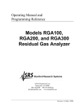
As shown in the figure below, the REA has 3 connectors: Serial DB9 male to SRS RGA,
an RJ45 to your network (with link speed and activity indicators), and a USB/B for power
(and optional setup). The serial number and MAC address of the REA can be found on
the back of the REA. A push button labeled IP SET on the back of the REA must be
depressed when power is applied to put the REA into setup mode.
Figure 1-1 Front and back panels
Five LED indicators on the top cover of the REA indicate activity and status.
LED indicators
Activity
POWER (Red)
ON = power on, OFF = power off
ETHERNET (Green)
ON = in “Ready for IP setup” state
OFF = no data activity
Fast Blinking = data activity
1 Hz blinking = DHCP running
4 Hz blinking = DHCP failed
USB (Green)
Blinking = data activity, OFF = no activity
RGA Tx (Yellow)
Blinking = data from RGA, OFF = no activity
RGA Rx (Yellow)
Blinking = data to RGA, OFF = no activity
Table 1-1 LED indicators
RGA Ethernet Adapter
8
Getting Started
RGA Ethernet Adapter
Chapter 1
9
Chapter 2
Configuration
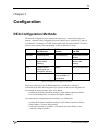
REA Configuration Methods
The network configuration can be performed in three ways: Automatically using your
network’s Dynamic Host Configuration Protocol (DHCP) server, manually for a static IP
over Ethernet, or manually over USB. Each method will be described in detail. The RGA
software works equally well with the REA in static or dynamic IP modes.
Software
Manual Static IP
over Ethernet
DHCP over
Ethernet
Manual Static IP
over USB
‘REASetupUtility’
‘REASetupUtility’
Serial communication
software
Prerequisite Details of IP address, DHCP server
Subnet mask,
Gateway
Details of IP address,
Subnet mask,
Gateway
Pros
Easiest
Best for programmers
DHCP server may
not be available on
your network.
Unforgiving, cryptic
Cons
Straight forward
menus guide you
through the process
Table 2-1 Comparison of configuration methods
Most users will prefer to use the REASetupUtility over Ethernet as it displays
information about other REA units that may be present on the network and guides the
user through the setup procedure. These users should:
1. perform the Software Installation and Quick Cable Check (instructions follow)
2. Use the REASetupUtility to configure the adapter (Chapter 3)
Users interested in configuring the REA manually over USB should:
1. perform the Software Installation and Quick Cable Check (instructions follow)
2. Read Chapter 4 - Remote Programming
3. Follow the instructions in Chapter 5 to install the optional USB driver and
manually configure the REA
RGA Ethernet Adapter
10
REA Configuration
Chapter 2
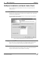
Software Installation and Quick Cable Check
Setup of the REA begins with installation of the software and a quick check of the
cabling and power:
1. Install the RGA Windows software
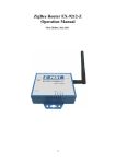
Install the RGA software from the CD. Make sure the “Setup REA Utility” install option
is checked (see screenshot below).
You must install the software with administrator account privileges because the RGA
program needs full "write" privileges.
Figure 2-2 Choose ‘Setup REA Utility’ in the RGA installer options
2. Apply power to the REA
Power up the REA by connecting the REA to the USB power adapter. Initially all the
LED’s are on for one second after which only the POWER LED should be on.
3. Connect to the network
Connect an Ethernet cable between the RJ45 connector on the REA and your network.
The green LED on the RJ45 connector should be on or flashing.
RGA Ethernet Adapter
Chapter 2
REA Configuration
11
RJ45 connector front
Green LED
Yellow LED
Figure 2-3 LED indicators on the RJ45 Ethernet port
Green LED for activity (ON = Linked, Blinking = Active, OFF = Disconnected)
Yellow LED for speed (ON = 100 BASE-T, OFF = 10 BASE-T)
RGA Ethernet Adapter
12
REA Configuration
RGA Ethernet Adapter
Chapter 2
13
Chapter 3
REA Setup Utility
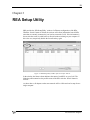
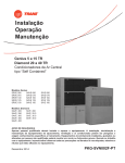
SRS provides the ‘REASetupUtility’ software for Ethernet configuration of the REA.
When the ‘Search’ button is clicked, the software will collect information from all REA
units that are currently connected to your local area network (LAN). If no information is
shown after the search, it could be due to firewall software running on your computer. If
this is the case, temporarily disable the firewall and try again.
Figure 3-1 REASetupUtility window after successful ‘Search'
In the window, the Status column indicates the status of each REA on your LAN. The
following table summarizes the possible states of the REA after the ‘Search’ button is
clicked.
As shown above, all adapters on the same network will be visible and can be setup from a
single computer.
RGA Ethernet Adapter
14
REA Setup Utility
Chapter 3
Status
Meaning
Ready for Setup
REA is in IP setup mode and waiting to be configured.
Available
REA is ready to use with the RGA software.
Out of Subnet
The IP address and the subnet mask are not on the
same network as your computer. This will prevent the
RGA software from connecting to the REA from your
computer. If you intend to operate the REA on a
different network from the one your computer is
currently on, this may be correct. Otherwise, ask your
network administrator to review the network values (IP
address, subnet, and gateway).
IP Change Failed
The last IP setting failed (no change occurs). Try again
with a different IP address.
IP Conflict
There is another device using the same IP address
online when REA is powered on. If this happens, the
ETHERNET LED will blink very fast (4 times each
second) for 3 minutes. Changing the IP address on the
REA or the other device is necessary. If the IP address
of the other device is changed, turn REA off and on to
get the ‘Available’ status.
Occupied
REA is already connected to another host computer.
DHCP Running
DHCP is in progress.
DHCP Failed
The DHCP negotiation has failed. This is usually
because there is no DHCP server active on your
network. It might also be due to a network security
measure such as MAC filtering. Ask you network
administrator for help.
Table 3-1 REA states after ‘Search’
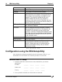
Configuration using the REASetupUtility
After choosing the configuration method based on the information in Table 2-1, you
should follow either the manual or the automatic procedure. Do not do both.
Manual Static IP Setup
1. Fill out the table below with the network values obtained from your network
administrator:
IP address
________
_______
_______
_______
Subnet mask
________
_______
_______
_______
Gateway
________
_______
_______
_______
2. Power up the REA and make sure all the cables are connected.
RGA Ethernet Adapter
Chapter 3
REA Setup Utility
15
3. Disable any anti-virus software or give permission to the ‘REASetupUtility’
software. Then start ‘REASetupUtility’ from Start>All Programs>SRS>RGA.
4. Reboot the REA into IP setup mode by following these steps:
i. Disconnect the USB power cable from the USB port of the REA.
ii. While pushing the IP SET switch, reconnect the USB power cable.
5. The green ETHERNET LED on top of the REA should be on. If not, repeat step 4
above. The REA will remain in the ‘Ready for Setup’ state for 5 minutes. If setup
does not occur during this time, the REA will return to its previous state.
6. In the ‘REASetupUtility’ software, click the ‘Search button.
7. Select the row with the ‘Ready for Setup’ status, then click the ‘Setup’ button (see
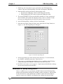
Figure 3-1). The following dialog box will appear.
Figure 3-2 Network setup dialog box
8. In the pop-up dialog, type in the network values from step 1. To avoid confusion,
give the REA a descriptive name here. Then click ‘Set’.
9. If the setup is successful, the status should now show ‘Available’ in the REASetup
window and the green ETHERNET LED on top of the REA will be off.
10. The REA is now ready to use. See page 16 - Login Parameter Modification to change
the user name and password of the REA.
Automatic IP Setup Using DHCP
If there is a DHCP server on your network, the DHCP function in the REASetupUtility
program will automatically configure the IP address, subnet, and gateway. After the REA
is set by this function, it will automatically use DHCP to obtain its network addresses
whenever it powers on. If DHCP is no longer desired, configure the network values
RGA Ethernet Adapter
16
REA Setup Utility
Chapter 3
manually (instructions above). After verifying with your network administrator that your
network has a DHCP server, follow these steps:
1. Skip step 1 of the manual setting procedure above. Follow steps 2 through 7 until you
reach the setup dialog box (Figure 3-2) for the selected REA.
2. In the setup dialog box, mark ‘Obtain IP automatically by DHCP’. The manual edit
section will be dimmed. Click the ‘Set’ button.
3. The REA will attempt DHCP negotiation for up to 90 seconds. During this process,
the ETHERNET LED on top of the REA will blink at 1 Hz.
4. Upon successful completion of the DHCP negotiation, the ETHERNET LED will
turn off. Clicking the ‘Search’ button again will display a status of “Available”.
5. The REA is now ready to use. To avoid confusion, it is a good idea to give the REA a
descriptive name. See below - Login Parameter Modification to change the user
name, password and device name of the REA.
Troubleshooting
If there is a conflict with the IP address (already assigned to another device or computer
on your network) during manual IP setup, the “Failed to Change” status will appear after
clicking the ‘Set’ button.
“Out of Subnet” status appears when the host computer and the REA do not have the
same network prefix in their IP address according to the subnet mask. (The network
address of the host PC is listed in the bottom right of the window.) In order to use the
REA on the same LAN, the network prefix portion of the IP address should match the
computer. If the REA will be used on a different network, it is fine to be out of subnet.
If the DHCP setup fails, the ETHERNET LED will blink at 4 Hz. Clicking the ‘Search’
button of the REASetupUtility program will confirm the failure by showing “DHCP
Failed” in the status column.
Login Parameter Modification
After the IP setup of the REA completes successfully, it is a good idea to modify the User
name and Password.
1. Select an REA whose status is ‘Available’.
2. Then click the ‘Modify’ button.
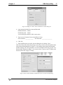
3. The Modify dialog box will appear as shown below (Figure 3-3).
RGA Ethernet Adapter
Chapter 3
REA Setup Utility
17
Figure 3-3 Modify User Name, Password and Device Name dialog box
4. Login using the default User name and Password.
Default Username: Admin
Default Password: Admin
A successful login makes the ‘Edit’ section active.
5. Type in a new Username, Password and Device Name.
New Username: ______________
New Password: __________________
6. Click ‘Set’.
7. If the modification is successful, close the dialog box by clicking ‘Close’.
If the User Name and/or Password settings are lost, they can be reset to the default values
in the Network Setup dialog box (Figure 3-2). By marking ‘Reset Name and Password’
and then clicking ‘Set’, these parameters are reset to the default. This brings up the ‘User
Password Info’ dialog box (Figure 3-4) to set new values. Type in a new User Name and
Password, then click ‘Apply’ to change.
Figure 3-4 Reset Name and Password followed by the User Password Info dialog
RGA Ethernet Adapter
18
REA Setup Utility
Chapter 3
Configuration Test
When an REA with ‘Available’ status is selected in REASetupUtility, the ‘Test’ button
will be active. This button tests the Ethernet connection between the PC and the selected
REA and between the PC and the RGA which is connected to the REA.
1. Select an REA with ‘Available’ status. The ‘Test’ button will be activated.
2. Click ‘Test’. The ‘AskUserPass’ dialog box will appear.
Figure 3-5 REA login dialog box
3. Type in the proper login parameters; User Name and Password, then click ‘Test
connection’.
4. The results of the connection test will appear in the ‘Test results’ dialog box below.
There are three steps in this test; login test, REA Ethernet connection test, and RGA
connection test. There is no setup for the connection between the REA and the RGA.
Only the physical connection with a DB9 male/female straight cable is needed. The RGA
should be on for this test. Figure 3-6 below shows the successful results of this test.
Figure 3-6 Test results box
RGA Ethernet Adapter
Chapter 3
REA Setup Utility
19
Connecting to the RGA Through Ethernet
Connection from ‘REASetupUtility’
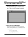
After passing the connection test successfully, the ‘Launch RGA’ button in the ‘Test
results’ dialog box is active as seen in Figure 3-6 above. Clicking ‘Launch RGA’ will
start the RGA Windows software (RGA.exe) to connect to the RGA over Ethernet via the
REA. Once connected, the RGA software will appear with the connection information
below the toolbar. Now you are ready to collect RGA data.
Figure 3-7 RGA software screenshot showing connection information below the toolbar
Connection from within the RGA Software
This section describes how to establish a connection to an REA/RGA from within the
RGA Windows software. This requires an REA with “Available” status (described
previously) connected to an RGA with a serial cable. The REA and the PC are connected
via LAN or cross-over Ethernet cable to each other. For a detailed reference of the RGA
software, please refer the RGA manual or ‘Help’ in the RGA software.
1. Connect all the cables.
• REA to RGA with an RS232 DB9 cable
• REA to LAN or PC with CAT 5e Ethernet cable
• REA USB to USB power adapter with a USB cable
RGA Ethernet Adapter
20
REA Setup Utility
Chapter 3
2. Turn on the RGA.
3. Run ‘RGA’
(Start>All Programs>SRS>RGA).
4. Click the Connection Settings button
.
5. Select the TCP/IP tab and check ‘Enable TCP IP Connections’.
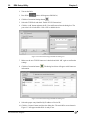
6. Click the ‘Add’ button and enter the IP, User and Password into the dialog box. The
port value is 818 for the REA. Click ‘OK’ to add this device.
Figure 3-8 Connection Settings and Ethernet dialog box
7. Make sure the new TCP/IP Connector is checked and click ‘OK’ again to confirm the
settings.
8. Click the Connection button
information.
. The dialog box below will appear with Connector
Figure 3-9 Connection Settings and Ethernet dialog box
9. Select the proper entry identified by IP address or Device ID.
10. Click the ‘Connect’ button and close the dialog box. The main RGA screen shown in
Figure 3-7 will appear and the RGA is ready to use.
RGA Ethernet Adapter
21
Chapter 4
Remote Programming and Errors
Introduction to Remote Commands
The REA may be controlled via Ethernet interface or USB interface. Any computer
supporting one of these interfaces can control the REA remotely.
Communication via Ethernet
You may connect the REA either directly to the host computer with a cross-over cable, or
to a hub or switch with a straight-through CAT5 cable. To connect the REA to a network
you will need an IP (Internet Protocol) address, subnet mask, and gateway address. See
your network administrator to obtain addresses appropriate for your network
environment.
Communication via USB
The REA has a USB B type receptacle for USB connection. When the REA is connected
to a host, the host enumerates the REA (and also powers the REA). Refer to Chapter 5 for
details. Once the enumeration completes, a user communicates with the REA as a serial
device.
Command Format
Communications with the REA uses ASCII characters. The REA is case insensitive, all
commands may be in either UPPER or lower case. A command starts with the character
following a termination character and ends with the following termination character. The
REA uses carriage return, <CR>, for a terminator.
The REA has two separate sets of commands that are processed differently. One is the
REA command set, which is processed by REA, and the other is the RGA command set,
which is directed to the attached RGA. The character ‘Z’ is used as a prefix character to
mark commands specific to the REA. A command starting with ‘Z’ is handled by the
REA and all other commands are handled by the attached RGA.
A command in the REA command set consists of a four character command mnemonic
with optional ?, arguments if necessary, and a command terminator. The command,
arguments and terminator may be separated by spaces. The terminator must be carriage
return <CR>. No command processing occurs until a <CR> is received.
RGA Ethernet Adapter
22
Remote Programming and Errors
Chapter 4
The present value of a particular parameter may be determined by querying the REA for
its value. A query is formed by appending a question mark ’?’ to the command mnemonic
and omitting the desired parameter from the command. Values returned by the REA are
sent as a string of ASCII characters terminated by a carriage return <CR>.
Command Syntax
The four letter mnemonic (shown in CAPS) in each command sequence specifies the
command. The rest of the sequence consists of parameters. Parameters shown in { } are
not always required. Generally, parameters in { } are required to set a value in the REA.
The present value of a parameter may be determined by sending a query command.
•
Commands that MAY be queried show a question mark in parentheses (?) after the
mnemonic.
•
Commands that are ONLY queries have a '?' after the mnemonic, with no
parentheses.
•
Commands that MAY NOT be queried have no '?'.
A query is formed by including the question mark ? after the command mnemonic and
omitting the queried parameter from the command. The query parameters shown in { }
are NOT sent with a query. The query returns the value of these parameters. Values are
returned as a string of ASCII characters (unless otherwise noted).
Do NOT send ( ) or { } as part of the command.
For example, the command sequence ZPTO (?) {n} is used as follows.
ZPTO 100
ZPTO ?
Set to 100
Query value
Variables are defined as follows.
n
i.i.i.i
s
integer
Dotted decimal integer format for IP address, subnet mask and
default gateway address (i is in the range 0-255)
text string for login name, password and device name
All integer variables should be expressed in integer format (i.e. the number five is 5, not
5.0 or 0.5E1). Strings are sent as a sequence of ASCII characters.
RGA Ethernet Adapter
Chapter 4
Remote Programming and Errors
23
Query Commands
ZQID?
Identification
Query ID string.
ZQFV?
Firmware Version
Query current firmware version.
ZQSN?
Serial Number
Query the serial number of the adapter.
ZQMC?
MAC Address
Query Media Access Control (MAC) address for the Ethernet port.
Error Query Commands
ZERR?
Query Error Code
Use “ZERR?” to read the error code. The most recent 10 error codes are stored
on the error stack. If there are more than 10 errors, the last error will replaced
with 126 (“Too Many Errors”). “ZERR?” returns the latest error first. You must
use ZERR? repeatedly until a ‘0’ is returned. A return value of ‘0’ indicates that
the error stack is empty and there are no errors to be read. For the complete list of
error codes, refer to the table at the end of this chapter.
ZEDS? n
Error Message
The ZEDS? n command queries the verbose error message string corresponding
to error number n (9 to 126 as returned with ZERR?). The parameter n is
required.
Parameter Setting Commands
Parameters changed with the following commands are saved in EEPROM,
preserved after power off and loaded when the REA starts again.
ZPIP(?) {i.i.i.i}
IP Address
The ZPIP i.i.i.i command sets the Internet Protocol (IP) address. The ZPIP?
query returns the current IP address setting.
Example
ZPIP 192.168.1.12
ZPIP?
sets the IP address to 192.168.1.12
returns the current IP address
RGA Ethernet Adapter
24
Remote Programming and Errors
ZPSM(?) {i.i.i.i}
IP Subnet Mask
The ZPSM i.i.i.i command sets the Internet Protocol (IP) subnet mask. The
ZPSM? query returns the current IP subnet mask setting.
Example
ZPSM 255.255.255.0
ZPSM?
ZPGW(?) {i.i.i.i}
sets the IP subnet mask to 255.255.255.0
returns the current IP subnet address
IP Default Gateway
The ZPGW i.i.i.i command sets the Internet Protocol (IP) default gateway. The
ZPGW? query returns the current IP default gateway setting.
Example
ZPGW 192.168.1.1
ZPGW?
ZPNM(?) {@s}
Chapter 4
sets the IP default gateway to 192.168.1.1
returns the current IP gateway address
User Name
The ZPNM @s command sets the user name string s. The ZPNM? query returns
the current user name.
The command accepts only alphanumeric characters, a-z, A-Z, and 0-9, up to 15
characters.
Examples
ZPNM @SRSRGA
ZPNM @
ZPNM?
sets the user name to “SRSRGA”
clears the user name
returns the current user name string
Note
With a blank user name and password, a user can login by typing carriage returns
only.
ZPPW(?) {@s}
Password
The ZPPW @s command sets the password to string s. The ZPPW? query returns
the current password.
The command accepts only alphanumeric characters, a-z, A-Z, and 0-9, up to 15
characters.
Examples
ZPPW @SRSRGA
ZPPW @
ZPPW?
sets the password to ‘SRSRGA’
clears the password.
returns the current password string
Note
With a blank user name and password, a user can login by typing carriage returns
only.
RGA Ethernet Adapter
Chapter 4
ZPDN(?) {@s}
Remote Programming and Errors
25
Device Name
The ZPDN @s command sets the device name to string s. The ZPDN? query
returns the current device name.
The command accepts only alphanumeric characters, a-z, A-Z, and 0-9, up to 15
characters.
Examples
ZPDN @DEVICE1
ZPDN @
ZPDN?
sets the device name to ‘DEVICE1’
clears the device name
returns the current device name
ZPTO(?) {n}
TCP/IP Connection Timeout
The ZPTO n command sets the TCP/IP connection timeout to n seconds (3 to
1800). The ZPTO? query returns the value n. If TCP/IP communication is
inactive for the timeout period, the connection will be closed. The default value
is 30 seconds. A power reset is needed to activate the changed value.
ZPRY(?) {n}
Reply to Ping or REA Search
The ZPRY n command sets the reply mode to ping (n=0) or REA Search (n=1).
The default value is n=1. ZPRY? queries the mode n.
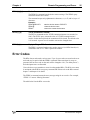
Error Codes
The REA detects and records various errors. Up to 10 error codes are stored on the error
stack and may be queried with the ZERR? command. When more than 10 errors are
generated, the last error code on the stack will be changed to 126 (“Too Many Errors”)
and subsequent errors are discarded.
Users also have to pay attention to errors from the attached RGA. The RGA error status
is monitored with the RGA error query command ER? Please refer to the RGA manual
chapter 7 and chapter 9 for details.
The ZEDS? n command returns the error message string for error code n. For example,
“ZEDS? 13” returns “Missing Parameter”.
The table below lists the REA error codes.
RGA Ethernet Adapter
26
Remote Programming and Errors
Chapter 4
Table 4-1 Error codes, messages and descriptions
Code
Message String
1-8
Reserved
9
“Invalid Command”
The command string does not start with a valid
command name.
10
“Incomplete Command”
The command string ends without a ? or a
parameter.
11
“Illegal Command”
Either a set only command was issued as a query
or a query only command was issued as a set.
12
Reserved
13
“Missing Parameter”
A second parameter in a set command is missing.
14
“Extra Parameter”
Extra character(s) follow a valid command.
15
“Out of Range”
A parameter is out of range.
16
“Bad Parameter”
A parameter is misformatted, such as an IP
address, a subnet mask, a gateway address, a
login name, or a password.
17
“Missing Comma”
Command string does not have a comma after the
first parameter.
18-19
Reserved
20
“Not a Number”
21
Reserved
22
“RGA on Network”
When TCP/IP connection is open, the serial
communication cannot talk to RGA.
23
“Command Buffer Full”
Too many commands to process before time
critical operations occur. Some of the commands
are rejected.
24
“RGA Buffer Full”
The RGA received too many commands to process
in time. Some of the commands are rejected.
25
Reserved
26
“String Too Long”
The login name and password should be 15
characters or less.
27
“Illegal Character”
The login name and password changing
commands, ZPNM and ZPPW accept
alphanumeric characters 0-9, A-Z, a-z only.
28
“RGA OFF”
Communication to RGA is not allowed when the
RGA is off.
29-125
Reserved
126
“Too Many Errors”
RGA Ethernet Adapter
Description
A parameter is not a number.
More than 10 errors have occurred since the last
“ZERR?” command. Subsequent errors have been
discarded.
27
Chapter 5
Configuration via USB
USB Driver Installation
If you choose to connect the REA USB cable to a computer, Windows should detect it
and start the "New Device Setup" wizard. Installation of the USB device driver is not
necessary unless you intend to manually configure the REA or program the RGA via
USB using a serial communications program.
1. Insert the provided CD into the PC.
2. Connect the adapter to any USB port of the PC using the provided USB cable.
3. Windows will detect the new hardware and start the “New Device Setup” wizard. If
your PC does not recognize the REA, try inserting a USB hub between the REA and
the PC.
4. At the start of ‘Found New Hardware Wizard’, when Windows asks to search for a
driver, choose ‘No, not this time’ to use the driver provided on the CD.
5. Next, select ‘Install from a list or from a directory’.
6. Navigate to the directory where the SrsRgaCommAll.inf file is (on the CD or in your
download directory if you are upgrading using the SRS web site). Then OK.
7. Press ‘Continue Anyway’ at the Microsoft credential warning.
8. After successful setup, Windows will indicate that the new hardware is “Ready to
use”.
9. Check the assigned COM port from Control Panel>System>Hardware>Device
Manager>Ports. A new COM port for SRS RGA Communication should appear.
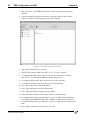
Manual IP Configuration over USB
After the USB COM port driver has been installed (above), any serial communication
software (e.g. HyperTerminal) can communicate with the REA. The following example
uses the serial communication software ‘rgacom.exe’ (included in the RGA software) to
demonstrate the configuration process. The RGA control software (on the REA CD or
downloaded from thinkSRS.com) must be installed before following this example.
1. Get the appropriate network values (IP address, Subnet mask, Gateway) from your
network administrator.
2. Make sure that the adapter is still connected through USB to the PC.
RGA Ethernet Adapter
28
REA Configuration via USB
Chapter 5
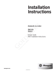
3. Run ‘rgacom.exe’ in the SRS\RGA directory which resides in the Program Files
directory.
4. Select the assigned COM port from the above procedure and click the ‘Connect’
button. The connector will change to green when connected.
Figure 5-1 Screenshot of rgacom.exe software.
5. Type ‘zqid?’ followed by the enter key.
6. The REA will respond “SRS_REA, S/N:*******, V.1.009” or similar.
7. To change the IP address, type ‘zpip ###.###.###.###’ and enter. For example
zpip 192.137.7.12 and enter. # indicates a numeric character 0-9.
8. To change the Subnet mask, type ‘zpsm ###.###.###.###’ and enter.
9. To change the Gateway, type ‘zpgw ###.###.###.###’ and enter.
10. Type ‘zpip? and enter to verify the IP address.
11. Type ‘zpsm? and enter to verify the Subnet mask.
12. Type ‘zpgw? and enter to verify the gateway address.
13. Check the values carefully. If they are not correct, re-enter the values.
14. To change the User Name, type ‘[email protected]’ (up to 15 alpha-numeric characters).
For example zpnm@MYREA1 then enter. s indicates an alpha-numeric character.
15. To change the Password, type ‘[email protected]’ (up to 15 alpha-numeric characters) and
enter.
16. Type ‘zpnm?’ and enter to verify the new user name.
RGA Ethernet Adapter
Chapter 5
REA Configuration via USB
29
17. Type ‘zppw?’ and enter to verify the new password.
18. To change the Device Name, type ‘[email protected]’ (up to 15 alpha-numeric characters)
and enter.
19. Type ‘zpdn?’ and enter to verify the new device name.
20. Select the connector again on the left side of the RGACOM window and click
disconnect.
21. Your REA is ready to use. Use ‘REASetupUtility’ to test the configuration as
described in Chapter 3.
RGA Ethernet Adapter
30
REA Configuration via USB
RGA Ethernet Adapter
Chapter 5