1
HSA Systems ApS
Page 1 of 61
HSAJET-CU user manual
HSAJET CU2 / CUF
USER
MANUAL
A guide to operating and
managing the HSAjet CU2
and CUF print controller
Last update 20 December 2011
HSA Systems ApS
Page 2 of 61
HSAJET-CU user manual
Introduction
Congratulations on the purchase of an HSAjet CU unit. You have a powerful stand-alone controller
with features compareable to PC-solutions. With full remote control, on-line editing of content,
security features and simple operation, this unit is suitable for many different applications.
For proper care of your unit, you should observe the following guidelines :
Do not unplug any cables while the unit is turned on
Do not take out the compact flash card while the unit is on
Do not take out cartridges (HP model) while the unit is in print mode
Preferably you should shut down unit properly before turning off power. This will correctly
close any open files on the compact flash card
You should make sure the CU does not get in contact with water. It is not under IP
protection.
Never remove the back panel with power on. Shock hazard!
IMPORTANT
NEVER try to insert the CF card by force. You may break the card connector,
resulting in replacement of motherboard. If you can’t easily fit the card, you may
have it the wrong way around.
Remote communication with the CU is not detailed in this
manual. Please see separate manual
"HSAJET CU REMOTE COMMUNICATION".
Copyright and Trademark Information
Microsoft, and Windows are US registered trademarks of Microsoft Corporation.
HP is a registered trademark of the Hewlett-Packard Corporation
This and other litterature on HSAjet products is © HS Automatic ApS 2005-2007. You may freely use this instruction and translate it,
as long as you do not change the content.
HSA Systems ApS
Page 3 of 61
HSAJET-CU user manual
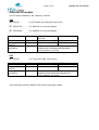
Different CU models
The CU will be available in the following versions:
CU2
CU2HP
For HP heads non-fused with max 2 pens
CU2XJ128
For Xaar128, up to 8 print engines
CU2XJ500
For Xaar500, up to 2 print engines
CU release
4.20
INKdraw version
Language Editor
Version
Language File
Information
1.12.xx
1.5
1856 byte
Firmware version
037/034
Firmware version 035
Firmware version 055
(Xaar)
(HP)
(Controller)
MD5:
08d931a2a37183b8bd1e28f35a2aa85a
CU2_firmware_v4_20.zip
CUF
CUFHP
CU release
INKdraw version
Language Editor
Version
Language File
Information
For F-type HP heads, up to 4 pens
4.20
1.12.xx
1.5
Firmware version 035
(HP F-Type)
Firmware version 055
(Controller)
1856 byte
MD5:
94686103c0e3ea8547dc09160eb3c478
CUF_firmware_v4_20.zip
All models have internal 100-240 VAC switch mode power supply.
HSA Systems ApS
Page 4 of 61
HSAJET-CU user manual
Features of the CU
Print using normal printers, xaar- or HP based.
Messages stored on standard Compact Flash cards.
Variable text, date, clock, counter and barcode
Prompt input of variables, 80 characters per line
Print height 140 mm (Xaar) / 50,8 mm (HP)
Separates message design and use
16 different fonts for variable objects, selectable among all windows fonts
Input of all Latin-1 character set directly from unit
Security features available to avoid unwanted editing of messages
Ethernet connection / serial connection, allowing full remote control of unit. This feature is
documented in separate manual.
Bidirectional print supported
HP cartridge parameters supported
Variable objects in other codepages changeable via RS232
HSA Systems ApS
Page 5 of 61
HSAJET-CU user manual
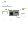
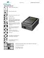
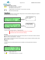
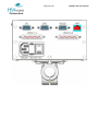
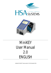
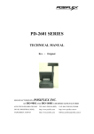
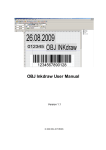
Connecting your CU
How you connect your CU depends on the type of CU you have. Please see this guide for
instructions on how to connect your unit.
RS232
serial
control
Encoder
Start sensor
Ethernet
connector
Print head
connectors
In general:
I/O and encoder connects using 9-pin SUB-D. Please see reference section for pinouts. It is
optional to use an encoder, but strongly recommended for best results.
Print heads connect through 25-pin SUB-D cables. In some cases through a dongle.
HSA Systems ApS
Page 6 of 61
HSAJET-CU user manual
CU2
HP version
1 pen
Use "Head 1-4" to connect first pen
1 + 1 pen
As above, and use "Head 5-8" for second pen
2 pen
Use "Head 1-4" for top pen, "Head 5-8" for bottom pen
Xaar 128 version
The first four engines (4 x 17,5mm or 2 x 35mm or 1 x 52,5mm or 1 x 70mm) connects to
"Head 1-4". If you have more than one ink supply to control your 4 engines per output, you may
chain them together.
You may connect "Head 5-8" similarly, for a total of max. 8 x 17,5mm print engines.
Max print height is 140 mm.
Xaar 500 version
Each connector "Head 1-4" and "Head 5-8" can connect 1 Xj500 printer.
Max print height is 140 mm.
HSA Systems ApS
Page 7 of 61
CUF
HP version
1 pen
Use "Head 1-4" to connect first pen
1 + 1 pen
As above, and use "Head 5-8" for second pen.
You need to connect through the CUF Dongle
2 pen
Use "Head 1-4"
2 + 1 pen
2 + 2 pen
You need to connect through the CUF Dongle
Part number: ACEL-HF-jumper-box
Please see section on jumperbox for CUF
3 pen
Use "Head 1-4"
4 pen
Use "Head 1-4"
HSAJET-CU user manual
HSA Systems ApS
Page 8 of 61
HSAJET-CU user manual
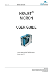
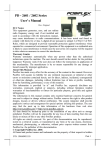
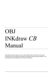
The CU keyboard
Used to start print activity
Enter the setup menu
Enter the previous menu or go
to main menu.
Stop print activity
Shift key. Use for capital letters
and with SETUP key to enter
extended setup
Space key, and ALT key. Hold
and press letter key for special
characters.
Arrow keys, use with enter to
select message navigate in
menus.
Up/down to select menu
screen, or to select values in
edit mode.
Left / Right to navigate menu
points within each screen.
Enter toggles edit mode or
accepts a choice
Object keys that allow editing of the 6 different object types
In order as they appear:
Text, Barcode, Clock,
Counter, Date, Logo
HSA Systems ApS
Page 9 of 61
HSAJET-CU user manual
Designing CU pictures
The CU pictures are designed using the OBJ INKdraw software. Please see OBJ INKdraw manual
for help on installing.
Concept of CU objects vs background
In a CU image, you have both static and variable content.
The static content
has no limitation, which means that you can design using any
font size and have all the barcodes available.
You are also rotate text, and span text across all heads
available.
It is not changeable once the CU file is made.
The variable content
(CU objects) are placed on top of the static content.
The variable content can change during print, and can be
changed by the user. There are some limitations on what you
can do with this object type.
Notice that in all cases, both variable and fixed objects are optional – you can design an all-static
or all-variable layout, or create a mix with both.
When you use variable objects, these will always be on top of static objects.
Please find a comparison below between variable and fixed content:
HSA Systems ApS
Page 10 of 61
HSAJET-CU user manual
Feature
Static Objects
Variable Objects
Can change
automatically during
print
NO
YES
Scales freely
YES
16 different fonts available, these
scale freely but each font type will be
same size
Position in message
Free, any position
Vertically limited to fixed position
relative to 32-pixel steps. Horizontally
free position
Rotates
YES
NO
Spans heads
YES, fills entire
message
NO, can ONLY print within head
boundary. HP: max 12.7mm high.
Editable
NO
YES
Font type
All available
Selection. Latin-1 type editable on
keyboard. Others only by remote
control
Length
Unlimited
Depends on object type. Text 80
characters. Dates / clocks 32
characters in output format
Object types available
Only text, graphics
and fixed
barcodes.
No objects that
auto-update, like
date, time…
Text and auto-update objects. Both
can be displayed as normal objects or
barcodes
Mandatory
No
No
As long as you are designing your picture in OBJ INKdraw, you can change both the background
and variable content. Once you compile the CU file (save it to compact flash drive as a CU file),
you can only edit the variable objects, on the CU unit itself.
HSA Systems ApS
Page 11 of 61
HSAJET-CU user manual
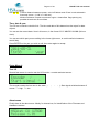
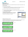
Start a CU picture
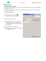
To start a CU picture, choose File->New on the menu, or click the "New File" icon. You will be
presented with a menu where you select the file type.
Select "Head type". You should select
the same type of head as your CU unit
is made for, you can’t load other file
types.
Check the "CU" option.
Add the heads as necessary with the
buttons below. With XaarJet500 you
will only have 1 size to choose from.
You are only allowed to add as many
heads as the CU can handle.
Select the message length. You can
change the unit between
mm/inch/pixel/point.
Click OK
HSA Systems ApS
Page 12 of 61
HSAJET-CU user manual
Once you have clicked OK, you are presented with the edit screen for CU files. Most of the screen
is identical to normal OBJ INKdraw pictures, but there are some differences.
Most importantly, a lot of the buttons are gone, and you see that there are 6 different CU objects
available, and that these are placed on the canvas by anchors (please see below).You will also
see the "CU Mode active" indicator right above the object panel.
A) Edit font for variable objects
B) Buttons for static objects
C) Buttons for variable objects
D) Compile to CU format
E) Static objects
F) Variable CU objects
G) Objects in this layout
H) Memory usage
HSA Systems ApS
Page 13 of 61
HSAJET-CU user manual
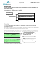
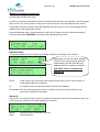
Working with font types / anchors
The variable CU objects, except the logos and barcodes, display textual information. Because of
it's resources, the CU is not able to place and scale fonts freely. That is why the font anchors were
made.
For every CU message you can choose up to 16 different fonts, each linked to an anchor with a
different color. Within each of the 16 fonts, you can choose between font type (Arial, Courier, and
every other installed true type font), a font size, bold - you can even stretch the font freely.
Within each anchor, you can change the font offset from top to bottom.
An anchor is defined as 1/4 of the XJ128 head, equal to 32 pixels. You can place the anchor freely
in the print direction (left/right), and in 32 pixels increments in the vertical direction.
Some illustrations will show the point of anchors:
Here is a purple and yellow anchor, with the
same font but different offsets from the
anchor.
You can see that the same anchor always
displays the same font. If you change an
anchor font definition, it will affect all variables
with that anchor color.
To have smaller text lines closer together,
use two anchors. The anchor itself is only
visible in design mode. They are not printed.
It is not a problem to define a font that is
larger than the anchor itself.
A) 2 different anchors
B) Anchors are offset at 32 pixels
C) To do this, you need 2 anchors
HSA Systems ApS
Page 14 of 61
HSAJET-CU user manual
To edit the anchor definitions, click the "A" button next to the anchor selector.
This will open the font
editor. Select the anchor
you wish to edit, and
change the font as needed.
You can leave the default
name (Name size (offset))
or make your own like "my
big font"
Click "Close" when done.
CU file sizes and fonts
The most space-demanding part of the CU files are the font files.
If you do not change any font settings, the CU files will occupy about 1-2 Mb on the CF card,
depending on the head type.
Notice that larger fonts increase the CU memory use. For example, a 70mm high font on Xaar500
will increase the font file to about 12 Mb. It is recommended to use smaller fonts.
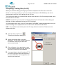
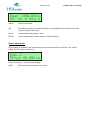
Preventing object editing
Sometimes it is necessary to prevent objects in the CU from being edited. This is possible by
locking the object in OBJ INKdraw before you compile the CU file.
To lock objects, right-click the object in the object list and select
"Locked". Now you can no longer select the object in OBJ INKdraw
canvas, and you can not edit in the CU.
If it is desired to allow editing, but only after entering a password,
set a CU password in the preferences menu. Then you can use the
same password to edit locked objects. Unlocked objects can always
be edited.
Preventing file change
If you wish to allow changes while printing but not in the file, save the file with a prefix of "_",
example "_file1.cu". This prefix will disable saving any changes to the file on the CF card.
HSA Systems ApS
Page 15 of 61
HSAJET-CU user manual
CU Objects
The CU has 6 different variable objects. All of them are editable directly on the unit itself by
pressing the corresponding object type key.
Dates
You can have a total of 10 different date objects, each with a user-defineable format
and individual offset.
The format follows the standard codes such as "dd", "mm" and "yyyy", although the
number of codes available are limited. You can choose from a pre-defined format, or
type in your own string.
Month names are available, and changeable in the language file. Use mmm, Mmm and
MMM for month names.
It is possible to use up to 32 characters in the date format string including quotes and
literals.
Counters
A total of 10 counters is available, each with a user-defineable start- and step value
Time
Allows 10 different clocks, each with a different time offset.
The clock is in 24-hour format, 12-hour format is currently not available.
Text
Up to 10 different text lines.
Logo
10 different logos are possible. These can be placed anywhere, and are not limited to
the position of an anchor.
Barcode
10 different barcodes are possible. Human-readable text is not supported but may be
placed as a separate object.
The barcodes can contain variable information in the shape of either text, counter, date
or time. It is not possible to have a barcode with multiple variable objects.
Notice that barcodes count against the 10 object limit in the respective object types. So,
if you have 5 counter barcodes, you can only have 5 normal counters.
HSA Systems ApS
Page 16 of 61
HSAJET-CU user manual
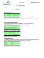
Other encodings
If you wish to use encodings that are different from English, you can select the encoding in the
dropdown under the CU box.
The CU ( InkDraw ) supports the following encodings and languages
Codepage
Language group
Win-1250
Central / Eastern Europe
Win-1251
Cyrillic
Win-1252
English / Western Europe
Win-1253
Greek (Modern)
Win-1254
Turkish
Win-1257
Baltic
Win-1258
Vietnamese
Win-932
Japanese (Shift-JIS), halfwidth KATAKANA only
The difference can be seen with a small demonstration. In this example, the actual text of the
object was not changed. Only the character set.
Default (Western Europe)
Russian
HSA Systems ApS
Page 17 of 61
HSAJET-CU user manual
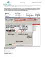
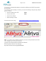
It is important to understand that whatever is entered into InkDraw must ALWAYS be entered in
Win-1252 format.
To use strings in other encodings, f.ex Greek, you must do the following. Using the string " Αθήνα"
(greek for "Athens")
Get text of original in Win-1253
Αθήνα
Convert to Win-1252.
ÁèÞíá
Insert this into InkDraw
Select encoding to "Greek"
Conversion can be done using
http://www.string-functions.com/encodedecode.aspx
HINT: If you update a string via RS232 or Ethernet, you must use the byte values from the Win1253 codepage to get correct greek characters.
A reference with character tables are available from Microsoft
SBCS (Single Byte Character Set) codepages:
http://msdn.microsoft.com/en-us/goglobal/bb964654
HSA Systems ApS
Page 18 of 61
HSAJET-CU user manual
Compiling / saving files (to CF)
When you are done editing your image, you need to compile the ink file to use it in the CU.
As this is a one-way process (i.e. you can not edit CU files later in OBJ INKdraw), the user is
recommend to save the .ink file along with the CU files.
The CU files are made of 2 individual files that are both required: A CU file with object data, and a
FNT file with the font data.
NOTICE : On the CU, you only need to change parameters for HP resolution while editing your
message. All other parameters are set on the CU unit itself.
You can however store a file on the CF card called "CUPARMS" containing parameters from your
current message - then upload to the CU. Do this in the "Advanced mode" below.
HINT : It is possible to save directly onto the CU using ethernet connection. Please see later
chapter about this.
Click the "Save to CF" icon.
This will open the Save dialog box.
Select the compact flash in the disc
dropdown. You can also choose to save on
the harddrive, and copy the files later.
(not recommended)
Enter a filename. It is a good idea to save
the ink file along with the CU file, since you
can't edit CU files from OBJ INKdraw.
It is a good idea to check "Auto-eject CF" if
you are not going to save more layouts on
the card. Otherwise, the file system on the
card may be destroyed.
HSA Systems ApS
Page 19 of 61
HSAJET-CU user manual
Saving files to PC network
If you have your CU connected in a PC network, you can save directly onto the CU unit. INKdraw
will upload the file for you.
To use this function, you must know the IP number of your CU, see in the shift - setup menu how
to check the IP number.
Then follow this procedure:
Click the "Save to CF" icon.
This will open the Save dialog box.
Select the “network” option
Enter a filename. You can use the same
name again if you only are interested in
transferring new data, the old file will simply
be overwritten.
Enter the IP number, in the form
Optionally you can load and / or print the file
after upload to your CU.
HSA Systems ApS
Page 20 of 61
HSAJET-CU user manual
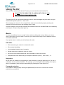
Using the CU
After you have saved the file to the CF card, you must insert the card into the CU.
DO NOT TRY TO FORCE THE CF CARD IN WITH TOP UP, YOU
WILL DESTROY YOUR CONTROLLER.
The idea of the CU is a unit that will allow the user to select messages and print them using the
standard HS Systems printers – Xaar or HP.
The messages are stored on the compact flash, and can be recalled by simply selecting the
filename from the main menu and pressing enter to load.
In each message, there can be both static and variable content. All variable fields can be edited by
pressing the corresponding object type key.
Basics
You have two different ”cursor modes” in the machine: editing and moving. When you enter a
menu, the cursor is in move mode. From here, you use the arrow keys to move between menus,
commands and fields.
If you press enter on a field, you will activate edit mode
Edit mode
Enter activates your selection or starts edit mode.
Esc cancels the editing
Insert toggles between insert / overwrite
Delete removes the character under the cursor
Arrow up / arrow down chooses the values just above / below the current.
Alt/Space with some letters will type european characters (Latin-1), such as á, ø, ú…
Navigation
At any point it is possible to jump directly to other sections by using the object keys. If you are in
edit mode, this is considered as ESC. For example, you could have finished editing a text object,
then it is possible to jump directly to date editing by pressing the ”Date object” key.
Password protection
It is possible to change setup values (print parameters) from the unit, but this menu can be
protected by a password.
HSA Systems ApS
Page 21 of 61
HSAJET-CU user manual
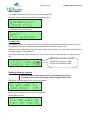
Print function
Activate the print function with the
active. Use ESC to stop print mode.
key. The red LED in the key will turn on if the print mode is
During print you can adjust the start distance with the arrow keys
00000
Number of prints with this picture. Is reset when a new picture is loaded.
000.00
Start delay. You can adjust by using the arrow keys, ◄ , ►, ▲ or ▼. (decimals)
mm
Units for start delay (mm / inch)
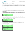
Prompts
When the print mode is actived, there can be prompts set on one or more objects. Prompts is a
way to ask the user to enter information that will be a part of the print, typically a best-before date
or batch number.
Prompts are shown with the object name and room for editing. It is possible to activate prompts for
the following objects:
Text (string). Max 80 characters.
Date (input format chosen in OBJ INKdraw preferences)
Time
Counter (start value)
Barcode (variable object inside).
Editing is cancelled with ESC, which deletes what is written. ESC again will cancel print start.
Navigation in prompts is done with the arrow keys. Use up/ down to jump a full screen if the text is
longer than 16 characters.
HSA Systems ApS
Page 22 of 61
HSAJET-CU user manual
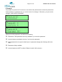
Main menu
You reach the main menu from any menu by pressing ESC.
The main menu is where you select the message to print.
or, if the current file is the active:
To load a file
It is simple to load a file. Use the arrow keys to browse the available files stored on the CF card, or
start typing the file name. Predictive type-ahead will find the best match for you.
When you have reached the correct file name, press enter to load it. You will see the text below the
file name change to ”File selected.”.
If you try to load a file that is not made for your unit, you will see a warning that you can't use this
file.
XJ500 files are invalid on XJ128
HP files are invalid on XJ128
HP files are invalid on XJ500
…
Shutting down the machine
When you wish to shut down the CU, you should exit properly
to minimize the risk of file damage on the Compact Flash card.
Press ESC from the main menu, and you are asked
Press Y to shut down the CU unit or N to continue.
Shortly after you see
HSA Systems ApS
Page 23 of 61
.. and you can turn the unit off on the power supply.
HSAJET-CU user manual
HSA Systems ApS
Page 24 of 61
HSAJET-CU user manual
Editing object / message content
With the CU, there is a separation between content and design. While it is possible to change the
size and position of objects in the design phase, this is not possible on the CU unit itself. Only the
following can be changed.
Content - except for logos.
Visibility (on/off)
You edit the object by pressing the corresponding object button. This can be done at any time,
even in print mode. (Notice though that there is a buffer of 2 prints, changes in print mode do not
happen instantly).
When you press an object button, you are presented with a list of objects of that type. If none are
found, you receive a notice about this:
If objects in the category exist, you will see a list of
objects, arranged by their order of appearance in INKdraw. Choose object with and .
Whan an object is selected, you see it's value and on/off setting. Use cursor to move down from
object name to edit field, and press Enter to edit value.
Notice: If the object name has (Bar) written next to it, it is contained inside a barcode. You can
then only see it's content, and need to edit it through the barcode menu. Please see the “special
case” section on next page.
What you see will depend on the object type.
HSA Systems ApS
Page 25 of 61
HSAJET-CU user manual
and will move 1 character
Shift / will move 1 screen
As you can see from the example to the left, the
text
The quick brown| fox jumps ove|r the lazy dog
is longer than one screen. You can scroll longer
messages by using arrows up/down.
Selecting "X" deletes the entire line content.
After a change, you are informed about the change.
Enter returns you to the object list.
Special case: Barcodes
If you choose a barcode, the format of the content will depend on the content type (Text / Counter/
date / time).
When you select the barcode, you can choose between the available barcodes with arrows
up/down. Then move the cursor with arrow right and press enter on "Edit content".
You will now see the edit screen for the content of the barcode
Once you are done editing the content, press ESC to exit to the barcode screen, or one of the
other object type keys.
HSA Systems ApS
Page 26 of 61
HSAJET-CU user manual
Input pictures for object types
Text
String, max 80 characters
Scroll using up/down. Input of special characters possible.
Date
Numbers, from an input mask.
The input mask is selected in OBJ INKdraw.
You do not need to enter separation characters.
Ex: 14-04-2005
Counter
Current value, entered as a decimal value. The number of digits can not be
changed.
Ex: 0000000
Barcode
Depending on the variable content.
Logo
Only visibility on/ off is possible
HSA Systems ApS
Page 27 of 61
HSAJET-CU user manual
Input of special characters
To enter special characters like 'ä' and 'ü' you hold down the space key (Labelled "Alt") and press
the key where the character is printed.
Similar characters are grouped on the same key, like on a cell phone, so that for example repeated
pressing of
and
will toggle through the following
á Á ä Ä å Å à À â Â ã Ã
The CU is able to print almost all extended characters in the ISO Latin 1 character set.
ISO Latin 2..15 is currently not supported in variable characters.
Please see reference section for a list of all characters and what key to use.
HSA Systems ApS
Page 28 of 61
HSAJET-CU user manual
Configuring your CU
On the CU, most settings are made directly on the unit itself. This means that in the design phase,
the designer can and should focus on design only. The operator / service responsible can and
should focus on hardware only – setting the offsets and parameters correctly.
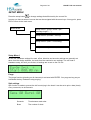
The configuration of the CU happens in two menus:
Setup
which is mostly related to the logical functions of the CU: offset
length, encoder parameters, etc. This is also the menu where
you can set the date/time of the unit, and get version
information.
System setup
which focuses more on the hardware part of the setup: how the
heads and engines are positioned in relation to each other and
the start sensor. Ethernet parameters are also set here. And,
this is where you set a password for the CU.
In both cases, the setup menus are working a several screens that are located below each other.
The navigation between screens are with cursor up/down, within each screen with cursor left/right.
As always, press enter to start and end edit mode, and to toggle values.
HSA Systems ApS
Page 29 of 61
HSAJET-CU user manual
SETUP MENU
Press the setup button
to change settings that affect mainly the current file.
In setup you have a series of menus that can be navigated with the arrow keys. At any point, press
ESC to return to the main menu.
MAIN MENU
Setup menu 1 (purge / Prime / spit /
message length / ….)
Setup menu 2 (encoder / velocity).
Setup menu 3 (Date / Time setting)
Setup menu 4: System info, test I/O.
Setup Menu 1
On the CU, hardware settings like start, offset, direction and encoder settings are generally not
taken from the design software, but used from the machine's own settings. You can load a
Hardware setup, but until you do that, all settings are as set on the CU unit.
Purge
The purge function (shooting on all channels) is activated with ENTER. You purge as long as you
hold down the key. Release to stop purging.
Spit settings
Spit function is made to prevent the ink from drying in the head. It can be set to print n dots (burst)
every x seconds, on all channels.
Seconds
Time between each shot
Burst
The number of shots
HSA Systems ApS
Page 30 of 61
HSAJET-CU user manual
Start distance / unit / sensor
000.00
Start distance (1/100" or 1/100 mm).
Max distance is 655,35 mm/ Inc.
mm/ In
Toggle between mm and Inches. The units will be converted
+
Start sensor pos/neg edge
Setup Menu 2
This section describes the printer settings. Setup menu 2 is the most basic settings for the printer,
that will have affect on this message.
Qad = Quadrature
Lin = Linear
Display changes if
you select Velocity.
Print settings
Top row is used to choose direction. Toggle with enter.
Please see section on birectional printing. You change
parameter sets with the direction setting.
Encoder
Enc is a toggle that selects between encoder and velocity modes. The value when encoder is selected
is written just like in OBJ INKdraw – mm/pulse.
Qua is a toggle for Quadrature (sensing on both channels, equal to 4 times the number of pulses. Qad
= Quadrature, Lin = Linear.
Velocity
In velocity mode, the encoder parameters are not available, only the speed can be entered as
m/minute.
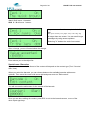
Setup Menu 3
Endl. Y
Toggle, endless. Y/N
Rep 00
Field, indicates repeat. 00 = no repeat.
HSA Systems ApS
Dist 000.00
Page 31 of 61
HSAJET-CU user manual
Field for distance between repeats – also in Endless mode. Enter in units selected in
first setup screen. (1/100" or 1/100 mm).
Minimum distance is equal to maximum engine + head offset. Page printing only
possible where there are no offsets.
Time, date & year
The CU has a real-time clock built-in. The time and date of this determines the output for date
objects.
You can set the current date / time in this menu, in the format YYYY-MM-DD HH:MM (24-hour
clock).
You can see which part you are editing in the lower right corner, to avoid confusion between
month/ day.
Press ENTER on the part you wish to edit, then enter again to accept.
Setup Menu 4
Test I/O
Second last screen is used to test the I/O function - encoder and start sensor.
The encoder rotates the bar next to the word ( /
arrows. = high, = low
|
-
\ ). Start signal switches between 2
About-menu
Finally there is the about-menu. Mostly for internal use, for identification of the Firmware and
Hardware versions.
HSA Systems ApS
Page 32 of 61
HSAJET-CU user manual
If you press Enter on the word "Release" you will see further information about FPGA and uP
version.
These numbers (Release, FPGA and uP version) are needed to HSA if you find a problem with
your machine.
HSA Systems ApS
Page 33 of 61
HSAJET-CU user manual
System setup
In system setup, you change the settings that are not related to the individual message, but are
more hardware related.
Press and hold SHIFT
MAIN MENU
, and press SETUP
Head setup
Load HW parameters. Enter ethernet
menu.
Passwords
Head setup
The CU is not born with a setup of heads. You can take the unit and connect it to different
configuration of printers.
The number and types of heads is stored inside the CU message and defined from INKdraw, but
you can adjust the head offset and engine offset to suit your needs.
When you enter Head Setup menu you see a list of the heads configured in the message, listed
with the number of engines per head in brackets. The total number of engines can not be more
than 8.
On an XJ500 machine, one
head has been set up
This is an XJ128 machine with
4 heads: 1, 2, 1 and 4 engines.
To change the settings for a head, press ENTER.
HSA Systems ApS
Page 34 of 61
HSAJET-CU user manual
000.00
Offset for the head.
Adj
Press Enter to adjust the engine offset(s). Only available if the head has more than
one print engine. See below.
Ups N
Is this head printing upside / down.
Oths N
Is this head printing on other side (in reverse direction)
Engine adjustment
Engine adjust is available if the head has more than one print engine (XJ128 for 2,3,4 engine
heads, and HP with 2,3,4 stall unit)
Select an engine (1..4) and choose settings
Offset
Offset from the first engine in the head.
HSA Systems ApS
Page 35 of 61
HSAJET-CU user manual
Managing Hardware parameters
Ink size/usage and Ethernet Setup
On the CU, all printing parameters (except HP resolution) are stored on the controller, not the message
that you load. This ensures that you only have to focus on layout, once the parameters are correct.
It is possible to store the settings from OBJ INKdraw and save to the CF card. These settings can be
loaded from the HW global setup screen.
From OBJ INKdraw select "Advanced Mode" in the save CU screen, and click "Save Hardware file".
This file will be called CUPARMS and should simply be placed on the card.
Ethernet Setup
To use the machine in a PC network, you should configure it's settings in the network.
Notice that you can not edit IP address
if DHCP is on, since it will be achieved
automatically. 000.000.000.000 until
address has been assigned by DHCP.
USE PORT 1500 to communicate
with the CU
DHCP
If this is set to ON, the machine will expect to find a DHCP server in the network, to
automatically obtain an IP address.
IP
If no DHCP server is used, the machine will use this IP address.
DeviceName The name this machine will have in a network. Only shown with command to get
device name (REQ:device name#)
Ink menu
In this menu, you can set the size of your ink container and monitor how much ink has been used. This
is also where you reset the value after replacing ink container.
Monitor
Mode
Select this menu to see use of ink (HP)
Choose between:
HSA Systems ApS
Page 36 of 61
Off (no low ink warning),
cart 42ml,
bulk 350ml and
user set.
HSAJET-CU user manual
Monitoring the ink menu
You can see the approx. remaining ink for each defined cartridge. Press ENTER on the number to
reset.
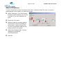
How to load Hardware settings
If you have saved a hardware setup file from INKdraw, you can load it by selecting
"Load HW settings". If a file is found and loaded, the CU will display
If you do not have a hardware file, you will see
Press ESC to return to previous menu.
Output configuration
The CU has 2 outputs on the start switch, out1 and out2. Each of these can be selected to give a
signal on the following: off (nothing), print mode, printing, fault, ink low(HP)
By default, the outputs are both set to "off".
HSA Systems ApS
Page 37 of 61
HSAJET-CU user manual
Password
It is possible to protect the CU so that no-one without the password can access the parameters.
If there already is a password set, you need to enter it to change it. Otherwise, you just need to
change it, and confirm it afterwards.
When you set the password, it will affect the following:
Parameters / HW parameters are only available if you know the password
Locked objects are editable, but only if you know the password
If NO password is set (equal to blank input on password change) the following will be the
case:
Parameters freely available
Locked objects can NOT be edited ("Object Locked" will be shown)
HSA Systems ApS
Page 38 of 61
HSAJET-CU user manual
Bidirectional Print
Bidirectional print allows you to have a printhead that traverses, and prints in each direction, using
the same message.
You should observe the following
A start signal is needed in both directions, into the same input. The first print must be in the
direction select for normal print. So printing are normal, reverse, normal,…
There are two different start offsets, one for each direction. See below
The time from the print is completed in one direction until the next start sensor is activated
must not be shorter than 80 mSec.
To activate Bidirectional Print
The mode must be activated from INKdraw. In Preferences,
select Printing, and under print buffer, “Bidirectional Print”.
Proceed as normal setting up your message.
Setting start offsets on the CU
On the CU, you can adjust the two individual start offsets by changing the print direction. The CU
will display a different start offset in the reverse direction if bidirectional is enabled.
Example: normal print direction is > (left to right)
If the other direction is selected
You will see and edit a different start distance
HSA Systems ApS
Page 39 of 61
HSAJET-CU user manual
Cartridge Parameters
When using a PC solution it is possible to set and configure parameter values for HP. Doing so
may optimize the output and quality on the HP cartridges, to adjust for each individual ink.
This option is now also possible on the CU, using latest beta version.
How to adjust HP parameters
From within INKdraw, select the parameter
menu, at HP Values.
You will now have two tabs available: the first
to set Resolution, the second with Cartridge
Parameters.
When you generate your CU message, these
parameters are automatically transferred and
used. You cannot modify or view these values
on the CU.
HSA Systems ApS
Page 40 of 61
HSAJET-CU user manual
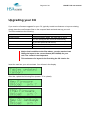
Upgrading your CU
If you receive a firmware upgrade for your CU, typically to add new features or improve existing,
simply place the new firmware files on the compact flash card and start up your unit.
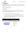
The files needed are the following:
CUENET.XXX
CUFIRMW.XXX
CUHPFPG.XXX
CULANG
KEYBCHAR.TAB
SPECCHAR.TAB
ethernet firmware update
CU firmware update
CU FPGA firmware update. HP could also be 128 or
500. The unit will pick the correct file automatically.
Language file. The length of the file must be respected
(so you can't upload an old version)
Character set for the CU keyboard
Another file for keyboard
Notice that in addition to the files above, you also need at least
ONE print layout in the correct format (HP/128/500) for your
unit. The content is not important.
This existence of a layout is the first thing the CU checks for.
Insert the card into your unit and start. You will see in the display
After that, upload the following files (answer "Y" to upload)
HSA Systems ApS
Page 41 of 61
HSAJET-CU user manual
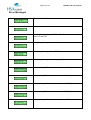
When you are done, remove all firmware files from the CF card.
If something should happen during upgrade, such as a power-out, the internal programs
could become damaged. In that case, you can upgrade the unit through cable via a
JTAG.
Please contact your distributor for instructions.
HSA Systems ApS
Page 42 of 61
HSAJET-CU user manual
Reference section
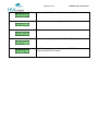
Language update
It is possible to change the language of the CU display, with the limitation that you are have fixed
length of the texts.
The editing of the language file happens with the free tool "Language File Editor" available from
HS Automatic.
Please see separate manual for this tool.
To use the language you have created, place the language file on the CF card with the name
"CULANG". You will be asked to upload the language.
HSA Systems ApS
Page 43 of 61
HSAJET-CU user manual
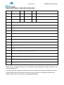
Keyboard layout, extended characters
1
! ¿ ¡
2
"
3
#
4
,
5
.
6
&
7
/
8
<
9
>
0
= ½ ¼ ¾
A
á Á ä Ä æ Æ å Å à À â Â ã Ã
B
\ { } [ ] |
C
ç Ç
D
ð Ð
E
é É è È ë Ë
F
* ÷ ×
G
:
H
;
I
í Í ì Ì ï Ï
N
ñ Ñ
O
ó Ó ö Ö ø Ø ò Ò ô Ô õ Õ
S
ß
T
Þ þ
U
ú Ú ü Ü ù Ù û Û
Y
ý Ý ÿ
Notice that due to display restrictions, your character may be displayed as a different character, but
will print as expected.
If you have selected a differenct character set in the CU object, the character will appear as above
on the display but will print a different character. Refer to section on encoding and tables from
MSDN. [http://msdn.microsoft.com/en-us/goglobal/bb964654]
HSA Systems ApS
Page 44 of 61
HSAJET-CU user manual
Error Messages
There are no CU files on the card.
No more room to write on the card.
You forgot to transfer the FNT file. The CU layouts consist of 2
files: CU and FNT
Something is wrong with the CU file
Something is wrong with the FPGA file
Something is wrong with the language file
You are using XJ500 model, and try to load XJ128 pictures.
You are using HP model, and try to load XJ128 pictures.
You are using XJ128 model, and try to load XJ500 pictures.
You are using HP model, and try to load XJ500 pictures.
You are using XJ128 model, and try to load HP pictures.
HSA Systems ApS
Page 45 of 61
HSAJET-CU user manual
You are using XJ500 model, and try to load HP pictures.
Can not load hardware settings without HW file.
Please make sure you insert the CF card during use
The CU can only read cards formatted in FAT 16.
Fat32 and NTFS will not work.
HSA Systems ApS
Connectors
Page 46 of 61
HSAJET-CU user manual
HSA Systems ApS
Page 47 of 61
HSAJET-CU user manual
FUSES
The CU2/CUF units have 4 fuses, 2 on the outside and 2 on the inside.
The outer fuses are on the supply voltage, they are located right next to the power socket. The
type is 2A Glass Fuse 5x20mm. If there is no reaction at all when you turn on the unit please check
these fuses.
The inner fuses are for the internal 5V and 12V DC supply for the I/O and encoder connectors.
The CUs can supply external equipment with 5 and 12V DC from the internal power supply.
F1 is the 5V fuse and F2 is the 12V fuse both are 0,5A SMD Fast acting. The value of the fuses is
related to the power available from the CU power supply. Use only 0,5A if you need more power
you must use an external power supply.
F1 and F2 are located inside the CU right next to the I/O connector.
You can buy the fuses from HSA or locally, if you choose locally make sure you get the right fuses,
warranty does not cover replacement of burned PCB’s because of wrong fuses.
Part number:
HSA
Farnell
Mouser
ACEL-Fuse-0,5A-SMD
9922156
576-0451.500MRL
ACEL-Fuse-2A-5x20
1123244
504-BK/S506-2-R
HSA Systems ApS
Page 48 of 61
HSAJET-CU user manual
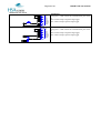
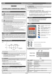
I/O CONNECTOR
Main function for this connector is to provide the start signal, to begin print. In the same connector
are also additional 2 output signals. It is located on the front of the CU, as a 9-pin female D-SUB
connector.
Output 1 = Active low (open collector)
Output 2 = Active low (open collector)
Input 1 = Not used
Input 2 = Not used
You can use either a simple mechanical switch or a photo cell for the start signal. The I/O
connector can supply 5V and 12V DC for the sensor but you can use any sensor in the 3-33V
range if you connect an external power source.
You can buy an I/O-ENC test box set from HSA which enables you to test:
I/O connector - Input 1, Input 2, Output 1, Output 2, Start signal input, 5V and 12V on the
I/O connector and an adjustable automatically continuous start signal is available.
Encoder connector - Enc A & Enc B channels, Low ink, 5V and 12V and an automatically
continuous encoder pulse generator is available.
Part number:
HSA
Product category
I/O-ENC test box set
Electric spare parts
5
1
9
6
PIN
1
2
3
4
5
6
7
8
9
Description
VIO – voltage reference
5V
Input 2 – Not used
Start signal input
GND
Input 1 – Not used
12V
Output 1
Output 2
HSA Systems ApS
Page 49 of 61
HSAJET-CU user manual
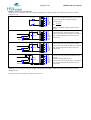
Mechanical start switch
1
6
2
7
3
8
4
9
5
VIO
IN1
5V
12V
IN2
OUT1
STSW
OUT2
GND
Pushbutton
Loop pins 1-2 and connect the switch between pins 4 and
5
N/O contact setup as negative edge trigger
N/C contact setup as positive edge trigger
1
6
2
7
3
8
4
9
5
VIO
IN1
5V
12V
IN2
OUT1
STSW
OUT2
GND
Relay
Loop pins 1-2 and connect the switch between pins 4 and
5
N/O contact setup as negative edge trigger
N/C contact setup as positive edge trigger
HSA Systems ApS
Page 50 of 61
HSAJET-CU user manual
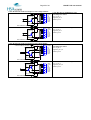
5V DC Sensor
PRODUCT
SENSOR
PRODUCT
SENSOR
1K
1
6
2
7
3
8
4
9
5
VIO
IN1
5V
12V
IN2
OUT1
STSW
OUT2
GND
5 Volt NPN or PUSH/PULL sensor
VCC to pins 1,2
Signal to pin 4
GND to pin 5
1
6
2
7
3
8
4
9
5
VIO
IN1
5V
12V
IN2
OUT1
STSW
OUT2
GND
5 Volt PNP sensor
VCC to pins 1,2
Signal to pin 4
GND to pin 5
1 K resistor between pin 4 and 5
1
6
2
7
3
8
4
9
5
VIO
IN1
5V
12V
IN2
OUT1
STSW
OUT2
GND
12 Volt NPN or PUSH/PULL sensor
VCC to pins 1,7
Signal to pin 4
GND to pin 5
1
6
2
7
3
8
4
9
5
VIO
IN1
5V
12V
IN2
OUT1
STSW
OUT2
GND
12 Volt PNP sensor
VCC to pins 1,7
Signal to pin 4
GND to pin 5
1 K resistor between pin 4 and 5
1
6
2
7
3
8
4
9
5
VIO
IN1
5V
12V
IN2
OUT1
STSW
OUT2
GND
NPN or PUSH/PULL sensor
VCC to pin 1
Signal to pin 4
GND to pin 5
1
6
2
7
3
8
4
9
5
VIO
IN1
5V
12V
IN2
OUT1
STSW
OUT2
GND
PNP sensor
VCC to pin 1
Signal to pin 4
GND to pin 5
1 K resistor between pin 4 and 5
12V DC Sensor
PRODUCT
SENSOR
PRODUCT
SENSOR
1K
3-33V DC Sensor with external power source
3-33VDC EXTERNAL SOURCE
PRODUCT
SENSOR
GND EXTERNAL SOURCE
3-33VDC EXTERNAL SOURCE
PRODUCT
SENSOR
1K
GND EXTERNAL SOURCE
HSA Systems ApS
Page 51 of 61
HSAJET-CU user manual
Output 1 Active low (open collector)
Warning: Do not connect a relay with a higher voltage than the voltage already connected to the VIO pin1 you will
damage the unit.
LED indicator
1
VIO
R VALUE
6
IN1
Connect the components between pins 2 and 8
2
5V
The R value can be calculated using the
7
12V
3
IN2
equation below
8
OUT1
4
9
5
1N4001
DIODE
RELAY
1N4001
DIODE
3-33VDC EXTERNAL SOURCE
1N4001
DIODE
GND EXTERNAL SOURCE
STSW
OUT2
GND
R
5 Ud
Id
Where Ud is diode voltage and Id is diode
current
5V DC relay
Connect the relay coil between pins 2 and 8
Some relays have a built in diode, if not please
also mount the protection diode on the coil
connections.
1
6
2
7
3
8
4
9
5
VIO
IN1
5V
12V
IN2
OUT1
STSW
OUT2
GND
1
6
2
7
3
8
4
9
5
VIO
IN1
5V
12V
IN2
OUT1
STSW
OUT2
GND
12V DC relay
Connect the relay coil between pins 7 and 8
Some relays have a built in diode, if not please
also mount the protection diode on the coil
connections.
1
6
2
7
3
8
4
9
5
VIO
IN1
5V
12V
IN2
OUT1
STSW
OUT2
GND
3-33V DC relay with external power source
Connect the relay coil between external VCC
and pin 8
Connect external GND to pin 5
Some relays have a built in diode, if not please
also mount the protection diode on the coil
connections.
Warning: Do not connect a relay with a higher voltage than the voltage already connected to the VIO pin1 you will
damage the unit.
The signal type can be selected in setup menu on the CU.
HSA Systems ApS
Page 52 of 61
HSAJET-CU user manual
Output 2 Active low (open collector)
Warning: Do not connect a relay with a higher voltage than the voltage already connected to the VIO pin1 you will
damage the unit.
LED indicator
1
VIO
R VALUE
6
IN1
Connect the components between pins 2 and 9
2
5V
The R value can be calculated using the
7
12V
3
IN2
equation below
8
OUT1
4
9
5
1N4001
DIODE
RELAY
1N4001
DIODE
3-33VDC EXTERNAL SOURCE
1N4001
DIODE
GND EXTERNAL SOURCE
STSW
OUT2
GND
R
5 Ud
Id
Where Ud is diode voltage and Id is diode
current
5V DC relay
Connect the relay coil between pins 2 and 9
Some relays have a built in diode, if not please
also mount the protection diode on the coil
connections.
1
6
2
7
3
8
4
9
5
VIO
IN1
5V
12V
IN2
OUT1
STSW
OUT2
GND
1
6
2
7
3
8
4
9
5
VIO
IN1
5V
12V
IN2
OUT1
STSW
OUT2
GND
12V DC relay
Connect the relay coil between pins 7 and 9
Some relays have a built in diode, if not please
also mount the protection diode on the coil
connections.
1
6
2
7
3
8
4
9
5
VIO
IN1
5V
12V
IN2
OUT1
STSW
OUT2
GND
3-33V DC relay with external power source
Connect the relay coil between external VCC
and pin 9
Connect external GND to pin 5
Some relays have a built in diode, if not please
also mount the protection diode on the coil
connections.
Warning: Do not connect a relay with a higher voltage than the voltage already connected to the VIO pin1 you will
damage the unit.
The signal type can be selected in setup menu on the CU.
HSA Systems ApS
Page 53 of 61
HSAJET-CU user manual
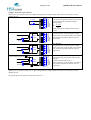
ENCODER CONNECTOR
This connector is where the signals for the encoder are coming in. The connector is located on the
front of the CU as a 9-pin female D-SUB connector.
The encoder connector can supply 5V and 12V DC for the encoder but you can use any encoder in
the 3-33V range if you connect an external power source.
5
1
9
6
PIN
1
2
3
4
5
6
7
8
9
Description
VENC – voltage reference
5V
Encoder A
Encoder B
GND
Not used
12V
/Encoder A (inverted)
/Encoder B (inverted)
5V DC Encoder single channel
1
6
2
7
3
8
4
9
5
VENC
Inklow
5V
12V
EncA
/EncA
EncB
/EncB
GND
5V DC NPN or PUSH/PULL
VCC to pins 1, 2
Signal to pin 4
GND to pin 5
1
6
2
7
3
8
4
9
5
VENC
Inklow
5V
12V
EncA
/EncA
EncB
/EncB
GND
5V DC PNP
VCC to pins 1, 2
Signal to pin 9
GND to pin 5
1
6
2
7
3
8
4
9
5
VENC
Inklow
5V
12V
EncA
/EncA
EncB
/EncB
GND
5V DC NPN or PUSH/PULL
VCC to pins 1, 2
Signals to pins 3, 4
GND to pin 5
1
6
2
7
3
8
4
9
5
VENC
Inklow
5V
12V
EncA
/EncA
EncB
/EncB
GND
5V DC PNP
VCC to pins 1, 2
Signals to pins 8, 9
GND to pin 5
5V DC Encoder dual channel
12V DC Encoder single channel
HSA Systems ApS
Page 54 of 61
HSAJET-CU user manual
1
6
2
7
3
8
4
9
5
VENC
Inklow
5V
12V
EncA
/EncA
EncB
/EncB
GND
12V DC NPN or PUSH/PULL
VCC to pins 1, 7
Signal to pin 4
GND to pin 5
1
6
2
7
3
8
4
9
5
VENC
Inklow
5V
12V
EncA
/EncA
EncB
/EncB
GND
12V DC PNP
VCC to pins 1, 7
Signal to pin 9
GND to pin 5
1
6
2
7
3
8
4
9
5
VENC
Inklow
5V
12V
EncA
/EncA
EncB
/EncB
GND
12V DC NPN or PUSH/PULL
VCC to pins 1, 7
Signals to pins 3, 4
GND to pin 5
1
6
2
7
3
8
4
9
5
VENC
Inklow
5V
12V
EncA
/EncA
EncB
/EncB
GND
12V DC PNP
VCC to pins 1, 7
Signals to pins 8, 9
GND to pin 5
12V DC Encoder dual channel
HSA Systems ApS
Page 55 of 61
HSAJET-CU user manual
3-33V DC Encoder with external power source single channel
3-33VDC EXTERNAL SOURCE
1
6
2
7
3
8
4
9
5
VENC
Inklow
5V
12V
EncA
/EncA
EncB
/EncB
GND
1
6
2
7
3
8
4
9
5
VENC
Inklow
5V
12V
EncA
/EncA
EncB
/EncB
GND
3-33V DC NPN or PUSH/PULL with
external power source
VCC to pin 1
Signal to pin 4
GND to pin 5
GND EXTERNAL SOURCE
3-33VDC EXTERNAL SOURCE
3-33V DC PNP with external power source
VCC to pin 1
Signal to pin 9
GND to pin 5
GND EXTERNAL SOURCE
3-33V DC Encoder with external power source dual channel
3-33VDC EXTERNAL SOURCE
1
6
2
7
3
8
4
9
5
VENC
Inklow
5V
12V
EncA
/EncA
EncB
/EncB
GND
1
6
2
7
3
8
4
9
5
VENC
Inklow
5V
12V
EncA
/EncA
EncB
/EncB
GND
3-33V DC NPN or PUSH/PULL with
external power source
VCC to pin 1
Signal to pin 3, 4
GND to pin 5
GND EXTERNAL SOURCE
3-33VDC EXTERNAL SOURCE
GND EXTERNAL SOURCE
3-33V DC PNP with external power source
VCC to pin 1
Signal to pin 8, 9
GND to pin 5
HSA Systems ApS
Page 56 of 61
HSAJET-CU user manual
5V DC simulated encoder with external power source
1
6
2
7
3
8
4
9
5
VENC
Inklow
5V
12V
EncA
/EncA
EncB
/EncB
GND
5V DC NPN or PUSH/PULL with external
power source
Loop pins 1-2
Signal to pin 4
GND to pin 5
1
6
2
7
3
8
4
9
5
VENC
Inklow
5V
12V
EncA
/EncA
EncB
/EncB
GND
5V DC PNP with external power source
Loop pins 1-2
Signal to pin 9
GND to pin 5
1
6
2
7
3
8
4
9
5
VENC
Inklow
5V
12V
EncA
/EncA
EncB
/EncB
GND
12V DC NPN or PUSH/PULL with external
power source
Loop pins 1-7
Signal to pin 4
GND to pin 5
1
6
2
7
3
8
4
9
5
VENC
Inklow
5V
12V
EncA
/EncA
EncB
/EncB
GND
12V DC PNP with external power source
Loop pins 1-7
Signal to pin 9
GND to pin 5
1
6
2
7
3
8
4
9
5
VENC
Inklow
5V
12V
EncA
/EncA
EncB
/EncB
GND
3-33V DC NPN or PUSH/PULL with
external power source
VCC to pin 1
Signal to pin 4
GND to pin 5
1
6
2
7
3
8
4
9
5
VENC
Inklow
5V
12V
EncA
/EncA
EncB
/EncB
GND
3-33V DC PNP with external power source
VCC to pin 1
Signal to pin 9
GND to pin 5
12V DC simulated encoder with external power source
3-33V DC simulated encoder with external power source
3-33VDC EXTERNAL SOURCE
GND EXTERNAL SOURCE
3-33VDC EXTERNAL SOURCE
GND EXTERNAL SOURCE
HSA Systems ApS
Page 57 of 61
HSAJET-CU user manual
RS-232 connector
This connector is used for remote communication with the CU2 / CUF, this section will tell you how
to connect the wires, please see the remote communication manual for port setup and commands.
The connector is 9 pin Male, and the pins are configured as master. If you wish to connect from a
standard PC com port you must use a crossed cable.
5
1
9
6
PIN
1
2
3
4
5
6
7
8
9
Crossed cable
Connector A pin 5 is connected to connector B pin 5
Connector A pin 2 is connected to connector B pin 3
Connector A pin 3 is connected to connector B pin 2
Description
Rx
Tx
GND
HSA Systems ApS
Page 58 of 61
HSAJET-CU user manual
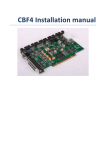
HF JUMPERBOX for CUF
HF Jumperbox for CUF is an accessory for CUF controllers which allows
you to use two physical heads with your controller.
The CUF is equipped with two ports, labelled "Head 1-4" and "Head 5-8".
Without HF Jumperbox the two ports will print the same data.
Part number: ACEL-HF-jumper-box
Instruction
The HF jumper box is supplied in a bag disassembled with two
jumpers mounted in neutral position, as illustrated.
To use:
1. Set jumpers to desired configuration - see below
2. Apply plastic cover and mount screws
3. Lock - only after mounting screws
4. Mount risers on female connector
5. Mount HF Jumper box on connector "Head 5-8"
6. Mount print head on other side of jumper box
Jumper settings
Head 1-4
Head 5-8
Head 1-4
Head 5-8
Head 1-4
Head 5-8
1 pen
1 pen
2 pen
1 pen OR 2 pen
3 pen
1 pen
Jumper set on 1-2
Jumper set on 3-4 and 5-6
Jumper set on 4-5
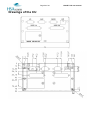
HSA Systems ApS
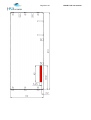
Drawings of the CU
Page 59 of 61
HSAJET-CU user manual
HSA Systems ApS
Page 60 of 61
HSAJET-CU user manual
HSA Systems ApS
Page 61 of 61
HSAJET-CU user manual
SUPPORT
For support on the CU2 / CUF please contact your local distributor or HSA Systems customer
service
Phone: +45 66 10 34 01
[email protected]