1
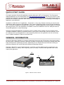
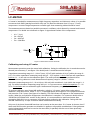
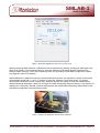
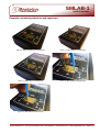
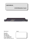
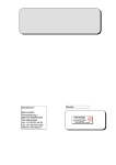
SMLAB-1
USER'S MANUAL
RF/Microwave Electronics
Rev 1F, Issued in April 2011, Revised in October 2011
SmartLAB
SMLAB-1
High Precision Digital USB LCF Meter and More
User's Manual
© 2011 Rantelon Ltd. ∣ TEL (+372) 6813650, FAX (+372) 6813651 ∣ www.rantelon.com
∣ [email protected] ∣ Page 1/13
RF/Microwave Electronics
SMLAB-1
USER'S MANUAL
TABLE OF CONTENTS
TABLE OF CONTENTS............................................................................................................................. 2
CONTACT INFORMATION........................................................................................................................ 2
QUICK START GUIDE.............................................................................................................................. 3
GENERAL INFORMATION........................................................................................................................ 3
LC-METER................................................................................................................................................ 5
Calibrating and using LC-meter............................................................................................................ 5
Examples: measuring inductors and capacitors....................................................................................7
Factors that affect inductance measurement accuracy.........................................................................8
FREQUENCY METER............................................................................................................................. 10
DDS FUNCTION GENERATOR.............................................................................................................. 11
PULSE GENERATOR............................................................................................................................. 12
SAFETY PRECAUTIONS........................................................................................................................ 13
COPYRIGHT........................................................................................................................................... 13
CONTACT INFORMATION
Rantelon Ltd.
RF/Microwave Electronics
Address:
Akadeemia tee 21G
12618, Tallinn
Estonia
Phone: (+372) 681 36 50
Fax: (+372) 681 36 51
Web: www.rantelon.com
E-mail: [email protected]
© 2011 Rantelon Ltd. ∣ TEL (+372) 6813650, FAX (+372) 6813651 ∣ www.rantelon.com
∣ [email protected] ∣ Page 2/13
SMLAB-1
USER'S MANUAL
RF/Microwave Electronics
QUICK START GUIDE
For proper operation SmartLAB application requires Microsoft .NET 2.0 Framework. The Framework
redistributable files can be downloaded from http://download.microsoft.com/ web site (use search to find
package that will match your operating system). Please note that you need to have administator rights to
perform the installation. Microsoft .NET Framework should be installed prior to installing or launching PC
application executable file!
Installation of SMLAB-1's PC application – SmartLAB – is very easy. Please note that you need to have
administator rights to perform the installation. First, find the application folder on the included installation
DVD. Locate the installation executable file and launch it. Installer application will then guide you through
the setup process. Once the application is installed, connect the SMLAB-1 to the PC USB port and run
SmartLAB application to start measuring!
If desired, SmartLAB application can also be used in portable mode. Simply copy the contents of the
"Portable Installation" folder to a desired location on your hard or thumb drive, connect SMLAB-1 to the
PC USB port and run the application to start measuring! Moreover, the application can be run directly
from "Portable Installation" folder on enclosed DVD.
GENERAL INFORMATION
Smart mini-laboratory SMLAB-1 is a perfect measuring instrument that RF designers have been waiting
for many years. Offered by Rantelon, SMLAB-1 provides an opportunity to clean your working desk from
bulky and expensive measuring monsters. Measuring set is a simple and smart USB box running on
personal computers with various Microsoft Windows operating systems.
Rantelon’s SMLAB-1 is an exceptional device, it includes a precise high frequency capacitance and
inductance meter (LC-meter), a RF frequency meter (F-meter), a DDS function generator and a dual
output pulse generator.
A
C
D
B
Figure 1. SMLAB-1 device overview
© 2011 Rantelon Ltd. ∣ TEL (+372) 6813650, FAX (+372) 6813651 ∣ www.rantelon.com
∣ [email protected] ∣ Page 3/13
SMLAB-1
USER'S MANUAL
RF/Microwave Electronics
Main connectors (as seen on figure 1):
•
•
•
•
A – through-hole (TH) and surface-mount device (SMD) LC meter connectors
B – frequency meter RF input
C – device USB connector
D – DDS function generator, pulse generator and frequency meter female header
E
F
G
H
Figure 2. SMLAB-1 accessories
Accessories (as seen of figure 2):
•
•
•
•
E – adapter for device female header
F – shorting plug for TH capacitance and inductance measurements and device calibration
G – range expanding capacitor
H – range expanding inductor
© 2011 Rantelon Ltd. ∣ TEL (+372) 6813650, FAX (+372) 6813651 ∣ www.rantelon.com
∣ [email protected] ∣ Page 4/13
SMLAB-1
USER'S MANUAL
RF/Microwave Electronics
LC-METER
LC-meter is intended for measurements of high frequency capacitors’ and inductors’ values. It is possible
to measure both SMD (starting from 0402 size) and TH (lead wire distance from 2,5 up to 7,5 mm)
components. In case of large components crocodile-type short measuring cables should be used.
The measurements are based on parallel resonance in oscillatory circuit formed by external and internal
components. For details see schematic on figure 3. Approximate values of the components:
•
•
•
•
Lk = 7,1 μH
Ck = 500 pF
Ce = 1000 pF
Fo = 2,66 MHz
Lk
Short
Lx
Ce
Cal
Ck
Cx
Figure 3. Measurement cirtcuit schematic
Calibrating and using LC-meter
Measurement procedure must be started with calibration. During the calibration the Lx terminals must be
shorted (use accessory F, see figure 2 for details) and Cx terminals must be left open.
Capacitance measuring range is 0 – 100 nF (max. 470 nF) with resolution 0,01 pF (within the range 0 –
1 nF). For wider capacitance measuring range 100 pF – 2 μF replace Lx short with low self-capacitance
inductor 0,1 – 1 mH and run the calibration again. The same procedure must be performed when
external measuring cables are used. Measurement frequency range is 2,6 MHz – 100 Hz.
Inductance measuring range is 0 – 10 mH (max. 100 mH) with resolution 0,1 nH (within the range 0 – 1
μH). For wider inductance measuring range 100 μH – 1 H put connect an additional capacitor 4,7 – 22
nF to Cx terminals and run calibration again. Measurement frequency range is 2,6 MHz – 100 Hz.
To perform calibration start SmartLAB application, switch to “LC-meter” mode either using tabs or
“Measure” drop-down menu, select “L” or “C”, install appropriate short/open on Lx/Cx physical terminals
and press the “CAL” button (see figure 4 for details). The red indicator will appear on the measurement
screen. When the red indicator disappeares, the calibration is complete. For connector details refer to
“GENERAL INFORMATION” section of this manual. It is recommended to wait few minutes after
connecting SMLAB-1 box to computers' USB port before performing the calibration. During this time
SMLAB-1 warmes up. It helps to achieve better measurement accuracy.
Only one of the three SmartLAB functions can be active at the same time. If LC-meter is chosen, then Fmeter and DDS function generator are disabled. It applies to all possible combinations. Pulse generator
works independently and can be used at the same time (in-parallel) with the one of three previously
mentioned functions.
© 2011 Rantelon Ltd. ∣ TEL (+372) 6813650, FAX (+372) 6813651 ∣ www.rantelon.com
∣ [email protected] ∣ Page 5/13
RF/Microwave Electronics
SMLAB-1
USER'S MANUAL
Figure 4. SmartLAB application interface in LC-meter mode
When measuring SMD inductors, calibration must be performed by directly shorting the SMD pads (see
figure 5 for details). This technique helps to avoid the influence of possible parasitic elements and
achieve higher accuracy. Use a non-conducting stick (not included) to hold SMD components in place
(see figures 9 and 10 for details).
When calibration is performed one can measure desired inductors' and capacitors' values choosing the
measurement mode with “L” and “C” buttons or using the “Measure” drop-down menu. For proper
measurement SMLAB-1 needs a some time. Wait few seconds for device to finish the measurement.
When measuring capacitors' values do not forget to install the shorting plug (accessory F, see figure 2 for
details) on Lx terminals. SMLAB-1 internal temperature and measurement frequency information is also
provided on application's measurement screen.
Figure 5. Shorting the SMD pads directly during calibration
© 2011 Rantelon Ltd. ∣ TEL (+372) 6813650, FAX (+372) 6813651 ∣ www.rantelon.com
∣ [email protected] ∣ Page 6/13
RF/Microwave Electronics
SMLAB-1
USER'S MANUAL
Examples: measuring inductors and capacitors
Figure 6. Wired coil inductor measurement
Figure 7. THM capacitor measurement
Figure 8. THM inductor measurement
Figure 9. SMD capacitor measurement
Figure 10. SMD inductor measurement
© 2011 Rantelon Ltd. ∣ TEL (+372) 6813650, FAX (+372) 6813651 ∣ www.rantelon.com
∣ [email protected] ∣ Page 7/13
SMLAB-1
USER'S MANUAL
RF/Microwave Electronics
Factors that affect inductance measurement accuracy
Real world inductor inductance depends on frequency. Inductance of one particular inductor may differ
significantly when measured at different frequencies. This is caused by following reasons.
Every inductor has parasitic distributed capacitance Cd between coil turns. The Cd does affect
impedance of the inductor. In region of self-resonance frequency ω effective inductance Le can be
higher than inductance L measured on relatively low frequencies:
Le =
L
.
2
1−ω ×L×Cd
As an example Coilcraft's “Mini Spring” series inductor's characteristics are given below (see figure 11).
Figure 11. Coilcraft's "Mini Spring" series inductor's characteristics
Usually large inductors' self-resonance frequency is low. Such inductors are typically used on relatively
low frequencies. That's why inductance of these inductors should be measured on low frequencies. It is
possible to do such measurements when an additional capacitor on Cx terminals is used.
In case of solid core inductors whose core is made from some magnetic material, like ferrite, the
frequency response is affected by frequency characteristics of the core material's magnetic permeability.
Core material sets the maximum working frequency of the inductor. As an example G3 core's material
characteristics are given below (see figure 12).
© 2011 Rantelon Ltd. ∣ TEL (+372) 6813650, FAX (+372) 6813651 ∣ www.rantelon.com
∣ [email protected] ∣ Page 8/13
SMLAB-1
USER'S MANUAL
RF/Microwave Electronics
Figure 12. Complex permeability vs frequency for G3 core material
Caused by skin and proximity effects, complex high frequency currents' distribution changes effective
wire dimensions and, as consequence, makes it frequency-dependant. Since inductance depends on
coil wire shape, it also depends on frequency.
In case of SMD inductor with small inductance (a few nH up to tens nH) the coil is usually made from
quite thin wire. As a result, active series resistance (at 2,6 MHz measurement frequency) practically has
the same value as reactance. That means quality or Q-factor of such coils is very low.
The error caused by inductor's active series resistance in LC-meter (when measuring small inductors)
can be expressed as follows:
2
Δ L = ±1,4 nH×Ω .
© 2011 Rantelon Ltd. ∣ TEL (+372) 6813650, FAX (+372) 6813651 ∣ www.rantelon.com
∣ [email protected] ∣ Page 9/13
RF/Microwave Electronics
SMLAB-1
USER'S MANUAL
FREQUENCY METER
Frequency meter can be used to measure frequency of a sine or cosine periodic signals within the range
from 200 kHz and up to 5 GHz.
Figure 13. SmartLAB application interface in frequency meter mode
To perform frequency measurements switch to “F-meter” mode either using tabs or “Measure” drop-down
menu, select desired frequency band and set acquisition time. Signal of interest must be applied at
SMLAB-1’s RF input (SMA) or digital input Fx (Female Header). In case of small frequencies 200 kHz –
200 MHz use digital input Fx. For higher frequencies 200 MHz – 5 GHz use RF input. For connector
details refer to “GENERAL INFORMATION” section of this manual.
Using digital input Fx and series resistance 10 kΩ it is possible to measure low frequency digital signals.
The duty cycle of the input signal must be around 50%. When previously described condition are met,
frequencies as low as 3 kHz can be measured.
Acquisition time should be set to 1 second or less. Short acquisition times prevent possible overflows of
built-in counter. For better accuracy longer (> 1 s) acquisition times can be used. In case of especially
long periods there is a possibility that the counter will be constantly overflowing and measurement
results will be wrong. Wait few seconds for device to finish the measurement.
Please check that input signal amplitude is within specified limits (see SMLAB-1 datasheet for details).
Ignoring these guidelines will lead to wrong measurement results. In worst case SMLAB-1 input circuits
will be damaged. With no input signal present F-meter will still show some random measurement results
because of the random noise always present in the input circuits.
Only one of the three SmartLAB functions can be active at the same time. If F-meter is chosen, then LCmeter and DDS function generator are disabled. It applies to all possible combinations. Pulse generator
© 2011 Rantelon Ltd. ∣ TEL (+372) 6813650, FAX (+372) 6813651 ∣ www.rantelon.com
∣ [email protected] ∣ Page 10/13
RF/Microwave Electronics
SMLAB-1
USER'S MANUAL
works independently and can be used at the same time (in-parallel) with the one of three previously
mentioned functions. SMLAB-1 internal temperature and built-in automatic prescaler value information is
also provided on application’s measurement screen.
DDS FUNCTION GENERATOR
Based on built-in direct digital synthesizer (DDS) SMLAB-1's function generator is capable to generate
signals of different waveforms (sine, triangle, saw, rectangle) within the frequency range 0 – 500 kHz
with resolution of 0,1 Hz.
Figure 14. SmartLAB application interface in function generator mode
To use function generator switch to “DDS” mode either using tabs or “Measure” drop-down menu, select
desired waveform and set frequency. Synthesized signal will appear at digital output DDS (Female
Header). For connector details refer to “GENERAL INFORMATION” section of this manual.
Using “UP” and “DOWN” buttons function generator output frequency can be tuned with selected
frequency step. It is possible to continuously change the output frequency using the “Frequency Tuning”
sliding bar. It may be convinient in some applications. Desired output frequency can be typed directly into
SmartLAB application's measurement screen.
Only one of the three SmartLAB functions can be active at the same time. If DDS function generator is
chosen, then LC-meter and F-meter are disabled. It applies to all possible combinations. Pulse generator
works independently and can be used at the same time (in-parallel) with the one of three previously
mentioned functions. SMLAB-1 internal temperature and selected waveform information is also provided
on application’s measurement screen.
© 2011 Rantelon Ltd. ∣ TEL (+372) 6813650, FAX (+372) 6813651 ∣ www.rantelon.com
∣ [email protected] ∣ Page 11/13
RF/Microwave Electronics
SMLAB-1
USER'S MANUAL
PULSE GENERATOR
Dual output pulse generator operates within the frequency range 3 kHz – 12 MHz. Duty cycle of each
output can be set independently.
Figure 15. SmartLAB application interface in pulse generator mode
To use pulse generator switch to “Pulse Generator” mode either using tabs or “Measure” drop-down
menu. Synthesized signal will appear simultaneously at two digital outputs G1 and G2 (Female Header).
For connector details refer to “GENERAL INFORMATION” section of this manual.
Pulse generator output frequecny can be set using the “Tuning” sliding bar within the “Frequency”
subsection. Pre-defined prescaler can be used to change the output frequency in a flexible way.
Duty cycle of the outputs G1 and G2 can be set independently. Use sliding bars within “Output 1” and
“Output 2” subsections to set desired duty cycle values.
Pulse generator works independently and can be used at the same time (in-parallel) with the one of
three SMLAB-1 functions: LC-meter, F-meter and DDS function generator. However, please keep in mind
that only one of the three previously mentioned functions can be active at the same time. For example, if
LC-meter is chosen, then F-meter and DDS function generator are disabled. It applies to all possible
combinations. SMLAB-1 internal temperature and selected prescaler information is also provided on
application’s measurement screen.
© 2011 Rantelon Ltd. ∣ TEL (+372) 6813650, FAX (+372) 6813651 ∣ www.rantelon.com
∣ [email protected] ∣ Page 12/13
RF/Microwave Electronics
SMLAB-1
USER'S MANUAL
SAFETY PRECAUTIONS
Never continue to use the unit after a malfunctioning or abnormality occurs. Should a malfunction
or abnormality (foreign matter gets inside unit, unit becomes wet, smoke emission, strange noise or odor,
etc.) ever occur, immediately stop using the unit and contact manufacturer. Contact information can be
found on the third page of this manual.
Never try to disassemble, repair or modify the unit. Servicing should be done only by qualified
personnel. Contact manufacturer for details.
Do not touch the unit if it is connected via USB cable to the personal computer and there is
lightning in your area. Lightning strikes create the risk of electric shock.
Do not install the unit in a location subject to high temperatures. Direct sunlight and direct exposure
to the heated air from a heater or other source can raise the interior temperature of the unit, creating the
risk of fire and accident.
When not in use. Store the unit in a location that is not subject to extremely high or low temperatures.
Storing the unit in a closed vehicle during summer months, in a location exposed to direct sunlight for
long periods, in a location exposed directly to the heated air of a heating device, or in a location exposed
to very low temperatures creates the risk of deformation, discoloration, and malfunction. When not using
the unit, store it in a location that is normally at room temperature.
Medical equipment. It is recommended that advice from a qualified expert be sought before using this
product in the vicinity of emergency/intensive care medical equipment. It is recommended that if you
have a pacemaker fitted you check with a medical expert before using this product.
Cleaning. Clean the unit with a damp (not wet) cloth, or an anti-static wipe. Never use household polish
as this will damage the product. Never use a dry cloth as this may cause a static shock.
Environmental. Do not expose to direct sunlight. Do not submerge any part of this product in water and
do not use it in damp or humid conditions, such as bathrooms. Do not expose this product to fire,
explosive or other hazardous conditions. For better environment protection please don't dispose this
product. In Estonia please visit www.eesringlus.ee web site for product recycling related information.
COPYRIGHT
© Copyright 2011, Rantelon Ltd. All rights reserved.
All information contained in given manual has been revised thoroughly. However, Rantelon accepts no
liability for any omissions or faults and assumes no responsibility for its use. Rantelon reserves the right
to change all hard- and software specifications and other product related documentation without notice.
No parts of this document may be reproduced, stored in a retrieval system, transmitted in any form or by
any means, electronical, mechanical photocopying, recording or otherwise, without prior written
permission from Rantelon.
All mentioned trademarks, logos, and copyrights are property of their respective owners.
© 2011 Rantelon Ltd. ∣ TEL (+372) 6813650, FAX (+372) 6813651 ∣ www.rantelon.com
∣ [email protected] ∣ Page 13/13