1
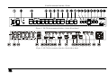
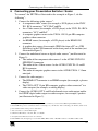
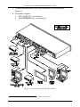
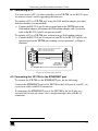
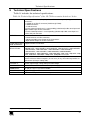
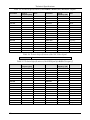
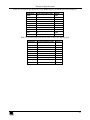
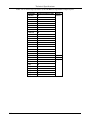
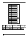
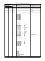
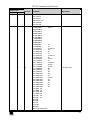
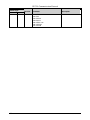
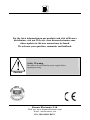
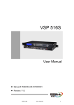
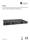
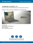
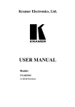
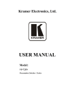
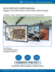
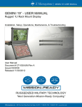
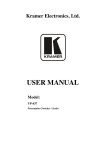
Kramer Electronics, Ltd.
USER MANUAL
Model:
VP-729
Presentation Switcher / Scaler
Contents
Contents
1
2
2.1
3
3.1
3.2
4
5
6
6.1
6.2
7
7.1
7.2
Introduction
Getting Started
Quick Start
Overview
About HDMI
Recommendations for Best Performance
Your Presentation Switcher / Scaler
Installing in a Rack
Connecting your Presentation Switcher / Scaler
Connecting a PC
Connecting the VP-729 via the ETHERNET port
Presentation Switcher / Scaler Buttons
Switching an Input
The PIP Button Feature
1
1
1
3
5
6
6
10
11
13
13
14
14
14
7.3
7.4
8
8.1
8.2
8.3
8.4
8.5
8.6
8.7
Locking and Unlocking the Front Panel
The Infra-Red Remote Control Transmitter
Configuring the VP-729 via the OSD MENU Screens
The Input Screen
The Picture Screen
The Output Screen
The PIP Screen
The Audio Screen
The Geometry Screen
The Setup Screen
17
17
19
20
21
22
23
24
25
26
8.8
9
10
Verifying Configuration Details via the Info Screen
Technical Specifications
VP-729 Communication Protocol
30
31
36
7.2.1
7.2.2
7.2.3
7.2.4
8.7.1
Activating the PIP Feature
Selecting the PIP Source
Quick Selection of the PIP Source
Toggling between the PIP and the Screen Source (Swap)
The Advanced Setup Screen
15
15
15
16
27
Figures
Figure 1: VP-729 Presentation Switcher / Scaler Front Panel
Figure 2: VP-729 Presentation Switcher / Scaler Rear Panel
Figure 3: Connecting the VP-729 Rear Panel
Figure 4: Connecting the PC
Figure 5: PIP Source Over Background
Figure 6: OSD SWAP Status
7
7
12
13
15
16
i
Contents
Figure 7: Infra-Red Remote Control Transmitter
Figure 8: MENU Items
Figure 9: Input Screen
Figure 10: Picture Screen
Figure 11: Output Screen
Figure 12: PIP Screen
Figure 13: Audio Screen
Figure 14: Geometry Screen
Figure 15: Setup Screen
Figure 16: Advanced Setup Screen
Figure 17: Firmware Download Screen
Figure 18: Information Screen
18
19
20
21
22
23
24
25
26
27
28
30
Tables
Table 1: Front Panel Presentation Switcher / Scaler Features
Table 2: Rear Panel Presentation Switcher / Scaler Features
Table 3: PIP Source Appearance Availability
Table 4: Infra-Red Remote Control Transmitter Functions
Table 5: Input Screen Functions
Table 6: Picture Screen Functions
Table 7: Output Screen Functions
Table 8: PIP Screen Functions
Table 9: Audio Screen Functions
Table 10: Geometry Screen Functions
Table 11: Available Settings for Each Application
Table 12: Setup Screen Functions
Table 13: Mode Set Functions
Table 14: OSD Functions
Table 15: Misc Functions
Table 16: Input Functions
Table 17: Output Functions
Table 18: Technical Specifications of the VP-729 Presentation Switchers / Scaler
Table 19: Technical Specifications of the RGBHV / RGBS (PC) / RGsB (PC) Signal
Table 20: Technical Specifications of the Y/C, Video Signal
Table 21: Technical Specifications of the DVI Signal (for RGB Colorspace)
Table 22: Technical Specifications of the HDMI Signal (for RGB or YUV Colorspace)
Table 23: Technical Specifications of the Component Input Signal
Table 24: Technical Specifications of the RGBHV/Comp/YPbPr Output Signal
Table 25: Technical Specifications of the HDMI/DVI/RGB Output Signal
Table 26: Technical Specifications of the 1920x1080 Output Signal
ii
8
9
16
18
20
21
22
23
24
25
25
26
27
27
28
29
29
31
32
32
32
33
33
34
35
35
KRAMER: SIMPLE CREATIVE TECHNOLOGY
Introduction
1
Introduction
Welcome to Kramer Electronics! Since 1981, Kramer Electronics has been
providing a world of unique, creative, and affordable solutions to the vast range of
problems that confront the video, audio, presentation, and broadcasting
professional on a daily basis. In recent years, we have redesigned and upgraded
most of our line, making the best even better! Our 500-plus different models now
appear in eight groups1 that are clearly defined by function.
Congratulations on purchasing your Kramer VP-729 Presentation Switcher /
Scaler, which is ideal for the following typical applications:
Projection systems in conference rooms, boardrooms, auditoriums, hotels and
churches
Production studios, rental and staging
Any application where high quality conversion and switching of multiple and
different video signals to graphical data signals is required for projection
purposes
The package includes the following items:
VP-729 Presentation Switcher / Scaler
Infra-red remote control transmitter
Power cord2 and null-modem adapter
This user manual3
2
Getting Started
We recommend that you:
Unpack the equipment carefully and save the original box and packaging
materials for possible future shipment
Review the contents of this user manual
Use Kramer high performance high resolution cables4
2.1 Quick Start
The quick start charts summarize the basic setup and operation steps of the
VP-729.
1 GROUP 1: Distribution Amplifiers; GROUP 2: Video and Audio Switchers, Matrix Switchers and Controllers; GROUP 3:
Video, Audio, VGA/XGA Processors; GROUP 4: Interfaces and Sync Processors; GROUP 5: Twisted Pair Interfaces;
GROUP 6: Accessories and Rack Adapters; GROUP 7: Scan Converters and Scalers; and GROUP 8: Cables and Connectors
2 We recommend that you use only the power cord that is supplied with this machine
3 Download up-to-date Kramer user manuals from our Web site at http://www.kramerelectronics.com
4 The complete list of Kramer cables is on our Web site at http://www.kramerelectronics.com
1
Getting Started
2
KRAMER: SIMPLE CREATIVE TECHNOLOGY
Overview
3
Overview
The Kramer VP-729 is a 9-input Proscale™ Presentation Switcher / Scaler
with unbalanced stereo and digital S/PDIF audio.
The VP-729 scales any composite, s-Video (Y/C), component video (YUV),
HDMI or computer graphics video signal, as well as jpeg files (via USB) up
or down to a selectable graphics or HDTV output resolution and provides
glitch-free switching between sources through FTB™ (fade-thru-black)
switching technology. The output signal is available simultaneously on a 15pin HD computer graphics video (UXGA) connector and on an HDMI
connector.
The VP-729 features include:
K-Storm™ Scaling Technology - Kramer’s extremely high performance
scaling technology. High quality 3:2 and 2:2 pull down1 de-interlacing and full
up and down scaling of computer graphics video input signals
Fade-Thru-Black (FTB™) Switching - the video fades to black and then the
new input fades from black for glitch-free and smooth switching. The output
signal provides constant sync so the display never glitches
K-IIT™ Picture-in-Picture Image Insertion Technology - ultra stable picture-inpicture image insertion capability. Any video source can be inserted into a
computer graphics video source or vice versa (or 2 images can be placed sideby-side) with positioning and sizing controls
Four user definable (universal) video inputs (each can be set as composite
video, s-Video (Y/C) or component video), two computer graphics video
inputs, two HDMI inputs and 1 USB input (for reading JPEG picture files2)
HDTV compatible component input
HDTV output resolutions - 480p, 576p, 720p 1080i, and 1080p
Scaled video outputs - HDMI and computer graphics video
HDMI supports up to 2.25Gbps bandwidth per graphic channel3
Multiple computer graphics output resolutions - including a user-defined output
resolution with selectable refresh rates
Multiple aspect ratio selections
Companion AFV (audio-follow-video) for every analog video input - supports
embedded audio on the two HDMI inputs and output
Built-in noise reduction and picture enhancement features
1 Accommodates the frame-rate of a converted movie (24 frames per second) to video frequencies (25 frames per second
(PAL); 30 frames per second (NTSC)
2 JPEG files in EXIF format are recognized, up to 1920x1200
3 Suitable for resolutions up to UXGA at 60Hz, and for all HD resolutions
3
Overview
Audio inputs - four (stereo audio or S/PDIF on 2 RCA connectors) for each of
the four universal video inputs; two stereo audio (on 3.5mm connectors) for the
two computer graphics video inputs; and embedded audio on the HDMI inputs
Audio outputs - S/PDIF and stereo audio (RCA connectors). Transcodes stereo
or S/PDIF audio to both stereo and S/PDIF audio and embeds audio onto the
HDMI output
Built-in Time Base Corrector - stabilizes video sources with unstable sync
Built-in video Proc-Amp - color, hue, sharpness, contrast, and brightness are set
individually for each input
A BLANK button, a FREEZE button, a RESET TO XGA/720P button (to
hardware-reset the output resolution); and a PANEL LOCK button1
Built-in audio Proc-Amp - with bass, treble, balance and loudness control, as
well as audio delay
Supports firmware upgrade2 via the USB port
An OSD (On-Screen Display) – for making adjustments – that can be located
anywhere on the screen, and can be doubled in size.
For example, the OSD can be used to deactivate the source prompt, choose the
color of the blank screen, and choose from three seamless switching image
transition speeds
In addition, the VP-729:
Includes non-volatile memory that retains the last settings, after switching the
power off and then on again
Digitally reprocesses the signal to correct mastering errors, and regenerates the
video at a higher line and pixel rate format, providing native-resolution video
for LCD, DLP and plasma displays
Is specifically designed to improve video quality by reducing chroma noise
Scales and zooms (to up to 400% of the original size)
Can provide non-linear scaling for 4:3, 16:9 transformation
Control your VP-729 directly via the front panel push buttons, or:
By RS-232 serial commands transmitted by a touch screen system, PC, or other
serial controller
Remotely, from the infra-red remote control transmitter (with on-screen menus)
Via the Ethernet
The VP-729 is housed in a 19” 1U rack mountable enclosure, with rack “ears”
included, and is fed from a 100-240 VAC universal switching power supply.
1 The front panel blank, freeze and lock buttons can be programmed via the OSD menu (see Table 15)
2 To check if firmware upgrades are available, go to our Web site at http://www.kramerelectronics.com
4
KRAMER: SIMPLE CREATIVE TECHNOLOGY
Overview
3.1 About HDMI
High-Definition Multimedia Interface (HDMI) is an uncompressed all-digital1
audio/video interface, widely supported in the entertainment and home cinema
industry. It delivers the maximum high-definition image and sound quality in use
today. Note that Kramer Electronics Limited is an HDMI Adopter2 and an HDCP
Licensee3.
In particular, HDMI4:
Provides a simple5 interface between any audio/video source, such as a set-top
box, DVD player, or A/V receiver and video monitor, such as a digital flat LCD
/ plasma television (DTV), over a single lengthy6 cable
Supports standard, enhanced, high-definition video, and multi-channel digital
audio7 on a single cable
Transmits all ATSC HDTV standards and supports 8-channel digital audio,
with bandwidth to spare to accommodate future enhancements and
requirements
Benefits consumers by providing superior, uncompressed digital video quality
via a single cable8, and user-friendly connector
Is backward-compatible with DVI (Digital Visual Interface)
Supports two-way communication between the video source (such as a DVD
player) and the digital television, enabling new functionality such as automatic
configuration and one-button play
Has the capacity to support existing high-definition video formats (720p, 1080i,
and 1080p/60), standard definition formats such as NTSC or PAL, as well as
480p and 576p
1 Ensuring an all-digital rendering of video without the losses associated with analog interfaces and their unnecessary digitalto-analog conversions
2 See http://www.hdmi.org/about/adopters_founders.asp
3 See http://www.digital-cp.com/list/
4 HDMI, the HDMI logo and High-Definition Multimedia Interface are trademarks or registered trademarks of HDMI
licensing LLC
5 With video and multi-channel audio combined into a single cable, the cost, complexity, and confusion of multiple cables
currently used in A/V systems is reduced
6 HDMI technology has been designed to use standard copper cable construction at up to 15m
7 HDMI supports multiple audio formats, from standard stereo to multi-channel surround-sound. HDMI has the capacity to
support Dolby 5.1 audio and high-resolution audio formats
8 HDMI provides the quality and functionality of a digital interface while also supporting uncompressed video formats in a
simple, cost-effective manner
5
Your Presentation Switcher / Scaler
3.2 Recommendations for Best Performance
To achieve the best performance:
Connect only good quality connection cables, thus avoiding interference,
deterioration in signal quality due to poor matching, and elevated noise-levels
(often associated with low quality cables)
Avoid interference from neighboring electrical appliances and position your
Kramer VP-729 away from moisture, excessive sunlight and dust
4
Your Presentation Switcher / Scaler
Figure 1, and Table 1 define the front panel of the VP-729; Figure 2 and
Table 2 define the rear panel.
6
KRAMER: SIMPLE CREATIVE TECHNOLOGY
Your Presentation Switcher / Scaler
Figure 1: VP-729 Presentation Switcher / Scaler Front Panel
Figure 2: VP-729 Presentation Switcher / Scaler Rear Panel
7
Your Presentation Switcher / Scaler
Table 1: Front Panel Presentation Switcher / Scaler Features
Function
Illuminated switch for turning the machine ON or OFF
Red when the unit accepts IR remote commands
Press to select the composite video / s-Video / component video
1
source (from 1 to 4)
4
5
6
Feature
POWER Switch
IR Receiver / LED
UNIVERSAL INPUT Selector
Buttons
UXGA 1
UXGA 2
HDMI 1
7
8
9
10
HDMI 2
USB
PIP Button
BLANK Button
11
12
13
14
FREEZE Button
MENU Button
ENTER Button
Press to select the HDMI source 2
3
Press to select the USB source
Toggles the picture-in-picture function (see section 7.2)
4
Press to toggle between a blank screen (blue or black screen) and the
display
4
Press to freeze/unfreeze the output video image
Displays the OSD menu screen (toggle)
Moves to the next level in the OSD screen, or accepts a new parameter
Decreases the range by one step in the OSD screen or moves to the
previous level in the OSD screen
Moves up one step (in the same level) in the OSD screen
15
16
17
18
19
20
INPUT Selector
2
Buttons
#
1
2
3
Button
Button
1
Press to select the UXGA source 1
1
Press to select the UXGA source 2
Press to select the HDMI source 1
Increases the range by one step in the OSD screen
Button
Moves down one step (in the same level) in the OSD screen
Button
RESET TO XGA/720p Button Press and hold for a few seconds to reset to the default output
resolution (XGA/720p @60Hz)5
PANEL LOCK Button
Press to lock/unlock the front panel to prevent unintentional operation
USB Connector
Connect to a USB drive to read JPEG files6
1 And the appropriate audio source
2 When selected, button illuminates. See section 7.1 for details of how to program the INPUT SELECTOR buttons
3 JPEG files in EXIF format on a USB memory stick
4 Can be programmed to mute the audio signal at the same time (see Table 15)
5 Press and hold for about 2 seconds to reset to XGA; or press and hold for about 5 seconds to reset to 720p
6 Files must be in EXIF format
8
KRAMER: SIMPLE CREATIVE TECHNOLOGY
Your Presentation Switcher / Scaler
Table 2: Rear Panel Presentation Switcher / Scaler Features
#
21
22
23
UNIV. IN RCA
Connectors
(from 1 to 4)
Feature
Function
24
UXGA 2 IN HD15 Connector
Connects to the UXGA (analog interface) graphics source 2
25
UXGA 1 IN HD15 Connector
Connects to the UXGA (analog interface) graphics source 1
26
HDMI 1 IN Connector
27
28
AUDIO IN UNIV. IN
RCA Connectors
(from 1 to 4)
29
HDMI 2 IN Connector
Connect to the HDMI 2 source
30
HDMI OUT Connector
Connect to the HDMI acceptor
31
UXGA OUT HD15 Connector
Connects to the video acceptor that displays the scaled output
In the default HDTV mode, the signal goes out via 3 PINS: PIN
1 is Pr, PIN 2 is Y, PIN 3 Pb
32
ETHERNET Port
Connects to your LAN1
33
34
AUDIO IN 3.5 Mini
Jack
35
RS-232 9-pin D-sub Connector
36
37
38
AUDIO OUT RCA
Connectors
39
Power Connector with Fuse
Y/CV
PB/C
PR
Connect to the video acceptor which can be either composite
video (Y/CV), s-Video (Y/CV, PB/C ) or component video (Y/CV,
PB/C, PR)
Connect to the HDMI 1 source
L, S/PDIF
R
UXGA 1
UXGA 2
L
R
S/PDIF
Connect to the left unbalanced stereo analog audio source;
Alternatively, connect to a digital audio source
Connect to the right unbalanced stereo analog audio source
Connects to the unbalanced stereo analog audio source 1
Connects to the unbalanced stereo analog audio source 2
Connects to PC or Serial Controller
Connect to the left unbalanced stereo analog audio acceptor
Connect to the right unbalanced stereo analog audio acceptor
Connect to a digital audio acceptor
AC connector enabling power supply to the unit
1 Local Area Network (that is, computers sharing a common communications line or wireless link, which often share a server
within a defined geographic area)
9
Installing in a Rack
5
Installing in a Rack
This section describes what to do before installing in a rack and how to rack
mount.
Before Installing in a Rack
Before installing in a rack, be sure that the environment is
within the recommended range:
Operating temperature range +5º to +45º C (41º to 113º F)
Operating humidity range
10 to 90% RHL, non-condensing
Storage temperature range
-20º to +70º C (-4º to 158º F)
Storage humidity range
5 to 95% RHL, non-condensing
How to Rack Mount
To rack-mount a machine:
1. Attach both ear brackets to the
machine. To do so, remove the
screws from each side of the
machine (3 on each side), and
replace those screws through the
ear brackets.
CAUTION!!
When installing on a 19" rack, avoid hazards by taking
care that:
1. It is located within the recommended environmental
conditions, as the operating ambient temperature of a
closed or multi unit rack assembly may exceed the
room ambient temperature.
2. Once rack mounted, enough air will still flow around
the machine.
3. The machine is placed straight in the correct
horizontal position.
4. You do not overload the circuit(s). When connecting
the machine to the supply circuit, overloading the
circuits might have a detrimental effect on overcurrent
protection and supply wiring. Refer to the appropriate
nameplate ratings for information. For example, for
fuse replacement, see the value printed on the
product label.
5. The machine is earthed (grounded) in a reliable way
and is connected only to an electricity socket with
grounding. Pay particular attention to situations where
electricity is supplied indirectly (when the power cord
is not plugged directly into the socket in the wall), for
example, when using an extension cable or a power
strip, and that you use only the power cord that is
supplied with the machine.
10
2. Place the ears of the machine
against the rack rails, and insert the
proper screws (not provided)
through each of the four holes in the
rack ears.
Note that:
In some models, the front panel
may feature built-in rack ears
Detachable rack ears can be
removed for desktop use
Always mount the machine in the
rack before you attach any cables
or connect the machine to the
power
If you are using a Kramer rack
adapter kit (for a machine that is not
19"), see the Rack Adapters user
manual for installation instructions
(you can download it at:
http://www.kramerelectronics.com)
KRAMER: SIMPLE CREATIVE TECHNOLOGY
Connecting your Presentation Switcher / Scaler
6
Connecting your Presentation Switcher / Scaler
To connect1 the VP-729 as illustrated in the example in Figure 3, do the
following2:
1. Connect the following video sources3:
A component video4 source (for example, a DVD player) to the UNIV.
IN 1 RCA connectors, Y/CV, PB/C and PR
An s-Video source (for example, a DVD player) to the UNIV. IN 4 RCA
connectors, Y/CV and PB/C
A computer graphics source to the UXGA 1 IN 15-pin HD computer
graphics video connector
An HDMI source (for example, a DVD player) to the HDMI 1 IN
connector
A graphics data source (for example, JPEG files from a PC or a USB
flash drive) to the USB connector on the front panel of the machine (not
illustrated in Figure 3)
2. Connect the unbalanced stereo or digital audio sources5 (not illustrated in
Figure 3):
The audio of the component video source 1 to the AUDIO UNIV IN 1
S/PDIF RCA connector
The audio of the s-Video source 4 to the AUDIO UNIV IN 4 L and R
RCA connector
The audio of computer graphics source to the AUDIO UXGA 1 3.5mm
mini jack
3. Connect the video outputs:
The HDMI OUT connector to an HDMI acceptor (for example, a plasma
display)
The UXGA OUT 15-pin HD computer graphics video connector6 to a
video acceptor (for example, an analog display)
4. Connect the AUDIO OUT L and R unbalanced stereo audio output and/or
the S/PDIF digital audio output to audio acceptors, for example, speakers
(not illustrated in Figure 3).
1 Although this example shows only several inputs that are connected, you can connect all the inputs simultaneously
2 Switch OFF the power on each device before connecting it to your VP-729. After connecting your VP-729, switch on its
power and then switch on the power on each device
3 You do not have to connect all the inputs
4 Sometimes called YUV, or Y, B-Y, R-Y, or Y, Pb, Pr
5 As required. Not all devices need to be connected
6 In the HDTV mode, the signal goes out via three PINS: PIN 1 is Red or Pr, PIN 2 is Green or Y, PIN 3 is Blue or Pb
11
Connecting your Presentation Switcher / Scaler
5. Connect the power cord1 (the power connector is not illustrated in
Figure 3).
6. If required, connect:
A PC via RS-232, see section 6.1
The ETHERNET port, see section 6.2
Figure 3: Connecting the VP-729 Rear Panel
1 We recommend that you use only the power cord that is supplied with this machine
12
KRAMER: SIMPLE CREATIVE TECHNOLOGY
Connecting your Presentation Switcher / Scaler
6.1 Connecting a PC
You can connect a PC (or other controller) to the VP-729 via the RS-232 port
for remote control, and for upgrading the firmware.
To connect a PC to a VP-729 unit, using the Null-modem adapter provided
with the machine (recommended):
Connect the RS-232 9-pin D-sub rear panel port on the VP-729 unit to the
Null-modem adapter and connect the Null-modem adapter with a 9-wire flat
cable to the RS-232 9-pin D-sub port on your PC
To connect a PC to a VP-729 unit, without using a Null-modem adapter:
Connect the RS-232 9-pin D-sub port on your PC to the RS-232 9-pin D-sub
rear panel port on the VP-729 unit, forming a cross-connection1, as Figure 4
illustrates
PIN 5 Connected to PIN 5 (Ground)
PIN 3 Connected to PIN 2
PIN 2 Connected to PIN 3
9-pin D-sub
(From PC)
9-pin D-sub
(To Presentation
Switcher/Scaler)
If a shielded cable is used, connect the shield to PIN 5
Figure 4: Connecting the PC
6.2 Connecting the VP-729 via the ETHERNET port
To connect the VP-729 via the ETHERNET port, do the following:
Connect the ETHERNET port of the VP-729 to the LAN port of your PC, via
a crossover cable with RJ-45 connectors.
If connecting the ETHERNET port of the VP-729 to the LAN port on a
network hub or network router, use a straight-through cable with RJ-45
connectors.
1 Also known as a Null-modem connection
13
Presentation Switcher / Scaler Buttons
7
Presentation Switcher / Scaler Buttons
The VP-729 includes the following front panel buttons:
Nine INPUT selector buttons, see section 7.1
A PIP button, see section 7.2
BLANK and FREEZE buttons
Six OSD buttons
A RESET TO XGA/720p button
A PANEL LOCK button, see section 7.3
7.1 Switching an Input
Each INPUT SELECTOR button can be used to select the source.
You can switch seamlessly1 between each input that is connected to a source,
by pressing the appropriate INPUT SELECTOR button.
7.2 The PIP Button Feature
The Picture-in-Picture inserter (PIP) uses K-IIT™ image insertion technology
to present video and graphic sources simultaneously2. You can display:
An inserted video source3 PIP over a graphic source4 display
An inserted graphic source4 PIP over a video source3 display
Three types of PIP insertions are available:
Picture-in-Picture – the PIP image appears over the background image
Picture + Picture – both the video source and the graphic source are placed side
by side and have the same height (the PIP image is stretched lengthwise)
Split – both the video source and the graphic source are placed side by side (the
PIP image appears smaller than the defined size and the source size is reduced)
1 FTB™ switching for glitchless transitions between inputs
2 Since the HDMI signal is HDCP protected, an HDMI signal cannot appear on a display that is not HDCP compliant
3 That is, composite video, s-Video or component video
4 That is, HDMI, USB or VGA
14
KRAMER: SIMPLE CREATIVE TECHNOLOGY
Presentation Switcher / Scaler Buttons
7.2.1
Activating the PIP Feature
You can activate the PIP by:
Pressing the PIP button
Pressing the PIP key on the infra-red remote control transmitter (see
section 7.4, Figure 7)
Switching on the PIP functionality via the OSD Menu (see Figure 12 and
Table 8)
7.2.2
Selecting the PIP Source
To use the PIP feature, set the PIP source via the OSD menu (see Figure 12 and
Table 8) by using the OSD front-panel buttons or the remote-transmitter keys.
To set the PIP source via the OSD menu, do the following:
1. Press the MENU button to enter the OSD menu.
2. Press the
button to move to the PIP icon.
3. Scroll down to select Source and press ENTER.
4. Use the or buttons to select the PIP Source from the drop-down list
box, and press ENTER (see Table 3).
5. To exit the OSD menu, press the MENU button.
Figure 5: PIP Source Over Background
7.2.3
Quick Selection of the PIP Source
For quick selection of the PIP source, press and hold the PIP front panel button
while pressing the input button of the required PIP source. For example, to select
UXGA 2 as the graphic PIP source over a video background, press the PIP front
panel button while pressing the UXGA 2 front panel button.
When attempting to select a PIP source of the same category as the background
source (for example, video on video, which is not compliant to Table 3),
a message is prompted: “unavailable operation”
15
Presentation Switcher / Scaler Buttons
To replace a PIP in the same category (for example, changing the PIP source
from UXGA 1 to HDMI 2), press the required PIP Source on the remote control
transmitter and the PIP display will change accordingly.
You can swap the PIP source category with the main source category via the:
Remote control keys, by selecting a new main source and then a new PIP source
OSD menu, by selecting a new Input source through the Input menu and a new
PIP source through the PIP menu
When selecting one PIP source, the Presentation Switcher / Scaler automatically
recognizes and displays the selected graphic PIP source on all the video displays1
and the selected video source on all the graphic1 displays, compliant to Table 3.
Table 3: PIP Source Appearance Availability
The selected PIP
source:
Composite video or s-Video
Appears on:
UXGA, HDMI, component video or USB Composite video or s-Video
Does not appear on:
Composite video or s-Video
7.2.4
UXGA, HDMI, component video or USB
UXGA, HDMI, component video or USB
Toggling between the PIP and the Screen Source (Swap)
To toggle back and forth between the PIP source and the main display, as
Figure 6 illustrates, press the Swap key on the infra-red remote control
transmitter (see Figure 7).
Figure 6: OSD SWAP Status
1 Even if the input signal is not connected. In this case the PIP appears over a blank screen
16
KRAMER: SIMPLE CREATIVE TECHNOLOGY
Presentation Switcher / Scaler Buttons
7.3 Locking and Unlocking the Front Panel
To prevent changing the settings accidentally or tampering with the unit via
the front panel buttons, lock your VP-729. Unlocking releases the protection
mechanism. When the front panel is locked, control is still available via
RS-232 and/or the ETHERNET connector.
To lock the VP-729:
Press the PANEL LOCK button on the front panel.
The front panel is locked and the PANEL LOCK button is illuminated. Pressing
a button will have no effect
To unlock the VP-729:
Press the illuminated PANEL LOCK button on the front panel
The front panel unlocks and the PANEL LOCK button is no longer
illuminated
For a description of the Save Lock and Input Lock OSD functions, see Table
15.
7.4 The Infra-Red Remote Control Transmitter
You can control the VP-729 remotely, from the infra-red remote control
transmitter, which:
Is a hand held instrument with a convenient keypad that receives its power from
2 AAA size 1.5V DC batteries
Has a range of up to 15 meters
Delivers instantaneous results
17
Presentation Switcher / Scaler Buttons
Figure 7 and Table 4 define the infra-red Remote Control Transmitter:
Table 4: Infra-Red Remote Control Transmitter Functions
key
Freeze
Function
1
Pauses the output video
Blank
Toggles between a blank screen (blue or black
screen) and the display
Cycles power
POWER
Main Source
9 separate keys for selecting each of the
following sources: Input 1, Input 2, Input 3, Input
4, VGA 1, VGA2, HDMI 1, HDMI 2 and USB
Reset
Press and hold to reset to the default resolution
2
Info
Shows the Info OSD menu
Capture
Capture an image to place as a logo or
background (see Table 15)
Shows the main OSD Menu
MENU
Navigation arrows
Allows maneuvering within an OSD screen (left,
right, up and down, as well as the ENTER arrow
at the center)
Auto Image
Assesses the image and improves the quality
accordingly, by automatically adjusting the
phase, frequency and position
Save
Saves a profile
Recall
Recalls a profile
Picture
Shows the Picture OSD menu
PIP source
9 separate keys for selecting each of the
following PIP sources: Input 1, Input 2, Input 3,
Input 4, VGA 1, VGA2, HDMI 1, HDMI 2 and
USB
Mute
Mutes the audio signal
Swap
Toggles between the PIP content and the parent
screen content
PIP
Selects the picture-in-picture function and
illuminates the PIP button3
Figure 7: Infra-Red Remote
Control Transmitter
1 Can be programmed to mute the audio signal at the same time (see Table 15)
2 Press and hold for about 2 seconds to reset to XGA; or press and hold for about 5 seconds to reset to 720p
3 See section 7.2
18
KRAMER: SIMPLE CREATIVE TECHNOLOGY
Configuring the VP-729 via the OSD MENU Screens
8
Configuring the VP-729 via the OSD MENU Screens
The OSD superimposes a menu on the screen from which you can configure
and control each input signal on your VP-729, using the MENU, ENTER, ,
, and OSD buttons on the front panel and the remote transmitter.
To use the OSD menus:
1. Select the desired input signal.
2. Use the menu buttons as follows:
Press the MENU front panel OSD button or the MENU key on the
infra-red remote control transmitter (see Figure 7) to display the main
MENU screen1, which displays eight interactive icons (see Figure 8)
Press the MENU front panel OSD button or the MENU key on the
infra-red remote control transmitter to move to the previous level in the
OSD screen (Esc)
Press the UP or DOWN buttons to select menu icons and then press
ENTER
Use + and – buttons to increase and decrease the (numerical) rate
respectively
Figure 8: MENU Items
1 Each icon represents a Level 1 function. In addition to Level 1, the OSD structure includes Level 2 (a subset of level 1),
Level 3 (a subset of level 2), Level 4 (a subset of level 3) and a numerical range
19
Configuring the VP-729 via the OSD MENU Screens
8.1 The Input Screen
Figure 9 and Table 5 define the Input screen.
Figure 9: Input Screen
Table 5: Input Screen Functions
Setting
Source1
Function
Select the source2
Selection/Range
Input 1, Input 2, Input 3, Input 4, VGA 1, VGA 2,
HDMI 1, HDMI 2 or USB
Input (1 to 4)
Source Type
Select the source type
Component, YC or video (CV)
Image Name
Color Format
Shows the file name3 that is
displayed when the USB port
is connected
Select the color format
Auto, RGB or YUV
Auto
Video Standard
Select the video standard
Auto, NTSC, PAL, PAL-M, PAL-N, NTSC 4.43,
SECAM or PAL-60
Auto
H-Position
Set the horizontal position4
The range changes according to the input mode
V-Position
Set the vertical position
Frequency
Adjust the frequency
0 to 26
0
Phase
Adjust the phase
0 to 31
0
Auto image
Assesses the image and improves the quality accordingly, by automatically
adjusting the phase, frequency and position
5
Default
Video
The range changes according to the input mode
1 When switching sources, the image fades through black
2 Automatically updated when pressing an input front panel button on the machine
3 Supports JPEG format only, including EXIF data (Exchangeable Image File Format). The JPEG file should not exceed a
resolution of 1920x1200. If the image file is not within the definition, the machine displays the message: “Non EXIF File” or
“Size Too Big”
4 For UXGA and component video inputs
5 For UXGA inputs
20
KRAMER: SIMPLE CREATIVE TECHNOLOGY
Configuring the VP-729 via the OSD MENU Screens
8.2 The Picture Screen
Figure 10 and Table 6 define the Picture screen.
Figure 10: Picture Screen
Table 6: Picture Screen Functions
Brightness
Setting
Function
Adjust the brightness
Selection/Range
0 to 100
Contrast
Adjust the contrast
0 to 100
Color
Adjust the color
0 to 100
55
Hue
Adjust the hue
0 to 360
180
Sharpness
Output Gamma
Adjust the sharpness
Adjust the gamma
0 to 100
Gamma 1 to Gamma 5
50
Gamma 1
Film Mode
Set the film mode
Auto, Video, Film
Auto
Temporal NR
Set the temporal noise
reduction level
Off, Low, Medium, High
High
Mosquito NR
Set the Mosquito noise
reduction level
Off, Low, Medium, High
Low
Off, On
Off
Off, Low, Medium, High
Medium
Off, Low, High
Low
Off, Low, High
Low
Block NR
Set the block noise
reduction level
Detail Enhancement
Set the detail
enhancement
Luma Transition Enhance
Set the luminance
transition enhance level
Chroma Transition Enhance Set the chrominance
transition enhance level
Default
50
50
21
Configuring the VP-729 via the OSD MENU Screens
8.3 The Output Screen
Figure 11 and Table 7 define the Output screen.
Figure 11: Output Screen
Table 7: Output Screen Functions
Setting
Resolution
Function
Set the resolution1
Selection/Range
Native HDMI, 640x480x60Hz,
640x480x75Hz, 800x600x60Hz,
800x600x60Hz, 800x600x75Hz,
1024x768x50Hz, 1024x768x60Hz,
1024x768x75Hz, 1280x768x50Hz,
1280x768x60Hz, 1280x1024x50Hz,
1280x1024x60Hz, 1280x1024x50Hz,
1366x768x50Hz, 1366x768x60Hz,
1400x1050x50Hz, 1400x1050x50Hz,
1600x1200x50Hz, 1600x1200x60Hz,
1680x1050x60Hz, 480p, 576p, 720p 50Hz,
720p 60Hz, 1080i 50Hz, 1080i 60Hz, 1080p
50Hz, 1080p 60Hz or Custom
Default
1024x768@60Hz
HDMI Type2
Set the HDMI type
Auto, HDMI, DVI
Aspect Ratio
Set the aspect ratio Standard, Letterbox, Anamorphic, Virtual
Wide, Native, Custom
Standard
Zoom
Set the Zoom
100%
Custom Zoom2
Set the Zoom
auto
H-Pan2
V-Pan2
H-Zoom 2
V-Zoom2
100%, 150%, 200%, 225%, 250%, 275%,
300%, 325%, 350%, 375%, 400%, Custom2
From 100% to 400%
Zoom H-Pan2
0 to 31
16
Zoom V-Pan2
0 to 31
16
1 Any change in the resolution must be confirmed via the count-down message that appears on the screen
2 Available for versions VTB 1.01 and higher
22
KRAMER: SIMPLE CREATIVE TECHNOLOGY
Configuring the VP-729 via the OSD MENU Screens
8.4 The PIP Screen
Figure 12 and Table 8 define the PIP screen.
Figure 12: PIP Screen
Table 8: PIP Screen Functions
Setting
On/Off
Function
Activate/deactivate the PIP
feature
Selection/Range
Type
Select the PIP type
Picture-In-Picture,
Picture + Picture or Split
Source
Select the PIP source1
Input 1, Input 2, Input 3, Input 4 or USB
(for a video PIP source)
PIP Size
H-Position
H-Size
Select the PIP size
Set the horizontal position of the
PIP on the display
Set the vertical position of the PIP
on the display
Set custom size
V-Size2
Set custom size
Default
Off
On/Off
Picture-InPicture
UXGA 1, UXGA 2, HDMI 1 or HDMI 2
V-Position
2
1/25, 1/16, 1/9, 1/4, or Custom2
0 – 128
1/4
3
0 – 128
0
Frame
Turn the PIP frame on or off
On/Off
On
Frame Color
Select the color of the PIP frame
Red, Green or Blue
Blue
1 When changing the PIP source, the display fades through black
2 Available for versions VTB 1.01 and higher
23
Configuring the VP-729 via the OSD MENU Screens
8.5 The Audio Screen
Figure 13 and Table 9 define the Audio screen.
Figure 13: Audio Screen
Table 9: Audio Screen Functions
Setting
Type
Input Volume
Function
Select the audio input type1
Adjust the input volume
Selection/Range
Analog or S/PDIF
-22 to 22
Default
Analog
0
0
Output Volume
Adjust the output volume
-100 to 24
Bass
Adjust the bass
-36 to 36
0
Treble
Adjust the treble
-36 to 36
0
Balance
Adjust the balance
-10 to 10
0
Loudness
Set the loudness
On/Off
Off
Delay
Define the delay type
Dynamic or User Define
3
Dynamic2
User Delay
Available when selecting the User
Defined delay
0 to 340 (msec)
0
USB
Select the audio signal to follow the
USB signal
No Audio, Input 1, Input
2, Input 3, Input 4, VGA
1, HDMI 1 or HDMI 2
No Audio
1 Available for IN 1 to IN 4
2 Dynamic means that the audio delay is equal to the pipeline video delay
3 In steps of 2msec
24
KRAMER: SIMPLE CREATIVE TECHNOLOGY
Configuring the VP-729 via the OSD MENU Screens
8.6 The Geometry Screen
Figure 14 and Table 10 define the Geometry screen, allowing the user
flexibility in positioning his projector relative to the screening surface.
Figure 14: Geometry Screen
Table 10: Geometry Screen Functions
Setting
Application
Location
Function
Selection/Range
Select the output application
Keystone, Anyplace or Rotation
Select the location of the
Front, Rear, Ceiling or Rear ceiling
display
Adjust the horizontal keystone1 -40 to 40
0
Vertical Keystone
Adjust the vertical keystone2
-30 to 30
0
Diagonal Projection
move the location of each
corner of the display
separately
Adjust the pincushion or barrel
appearance of the screen
Rotate the display by 180
degrees clockwise or
counterclockwise
Top Left, Top Right, Bottom Left,
Bottom Right or Reset (to reset
diagonal projections settings)
-20 to 20
Top Left
0
-180 to 180
0
Horizontal Keystone
Pincushion/Barrel
Rotation
Reset all
Default
Keystone
Front
Resets the geometry values to their default value
Table 11 defines the settings available for each application:
Table 11: Available Settings for Each Application
Application
Available Settings
Keystone
Location, horizontal keystone, vertical keystone, pincushion/barrel and Reset all
Anyplace
Location, Diagonal Projection and Reset all
Rotation
Location, pincushion/barrel, Rotation and Reset all
1 If the projector is located at an angle to the left or right of the screen
2 If the projector is located at an angle above or below the screen
25
Configuring the VP-729 via the OSD MENU Screens
8.7 The Setup Screen
Figure 15 and Table 10 define the Setup screen.
Figure 15: Setup Screen
Table 12: Setup Screen Functions
Save1
Setting
Function
Selection/Range
From Profile 1 to Profile 8
Save a profile
Recall1
Recall a profile
From Profile 1 to Profile 8
Frame Lock
Locks the vertical refresh rate of the
output to that of the input2
Reset your VP-729 to its preset
default settings
Open the advanced setups (see
Figure 16)
On/Off
Factory Reset
Advanced Setup:
Default
Off
Yes/No
Mode Set (see Table 13)
OSD (see Table 14)
Misc (see Table 15.)
Input (see Table 16)
Output (see Table 17)
1 Available for versions VTB 1.01 and higher
2 Note that seamless switching is not possible when working in the Frame Lock mode unless all sources are frame
synchronized
26
KRAMER: SIMPLE CREATIVE TECHNOLOGY
Configuring the VP-729 via the OSD MENU Screens
8.7.1
The Advanced Setup Screen
Figure 16 and Table 14 to Table 17 (inclusive) define the Advanced Setup
screen.
Figure 16: Advanced Setup Screen
The Mode Set functions define the desired working resolution and refresh rate
when the system cannot distinguish between similar resolutions and refresh
rate values (see Table 13).
Table 13: Mode Set Functions
Setting
Mode 11
Function
Set mode 1
Selection/Range
1400x1050x60Hz
1680x1050@60Hz
Default
1400x1050x60Hz
Mode 21
Set mode 2
1280x1024x75Hz
1280x1024x76Hz
1280x1024x75Hz
Table 14: OSD Functions
Setting
Menu Position
Function
Set the location of the OSD menu
Selection/Range
Center, Top Left, Bottom
Left, Bottom right
Default
Top Right
Time Out (sec)
Set the OSD menu timeout
5, 10, 20, 30, 60, 90 or Off
30
1 Available for versions VTB 1.01 and higher
27
Configuring the VP-729 via the OSD MENU Screens
Table 15: Misc Functions
Setting
Function
Selection/Range
Choose ON for the start up logo to On, Off or Custom
appear on the screen
OFF for it not to appear
Set to Custom to download a
1
custom Logo (Flash ROM)
Default
Kramer Logo
Blank Color
Set the blank color (the color that
appears on the screen when the
blank button is pressed)
Black or Blue
Blue
Capture
Press to capture the desired
2
image input to Flash ROM for
using as a logo or as the
background
Prompts “Capture”
If the image size is not within
the definition, prompts “Size
Too Big”
Background
Set the background screen color
Blue, Black, Custom3
Save Lock
Set the Save Lock option to ON to On/Off
save the lock status when the
machine is powered down
Off
Input Lock
Set the Input Lock to OFF so you
can still use the SOURCE buttons
on the front panel even when the
lock button is on
Download the firmware via the
USB connection (see Figure 17)
Download a new logo via the USB
connection
Define the function of the BLANK
front panel button
Define the function of the
FREEZE front panel button
Off
Logo
Firmware Download
Logo Download
Blank
Freeze
On/Off
Default
Confirmation
Blank & Mute, Blank, Mute
Blank & Mute
Freeze & Mute, Freeze, Mute
Freeze &
Mute
Figure 17: Firmware Download Screen
1 Obtained via the Capture function or downloaded via USB
2 The capture image size should not exceed 1280x1024
3 Obtained via the Capture function or downloaded via USB. Available for versions VTB 1.01 and higher
28
KRAMER: SIMPLE CREATIVE TECHNOLOGY
Configuring the VP-729 via the OSD MENU Screens
Table 16: Input Functions1
Setting
H Total
Function
Range
Default
Horizontal Total
H Start
Horizontal active start point
H Active
Horizontal active region
V Total
Vertical Total
V Start
Vertical active start point
V Active
Vertical active region
Ch, Pump
Charge pump current
H Freq
Horizontal Frequency
V Freq
Vertical Frequency
Color
Color format
Save
Save settings
Erase
Erase settings
Measure
Select between Default and User Define
Table 17: Output Functions1
Setting
HT
Function
Horizontal total
HW
Horizontal sync pulse width
HS
Horizontal active start point
HA
Horizontal active region
HP
VT
Horizontal polarity
Vertical total
VW
Vertical sync pulse width
VS
Vertical active start point
VA
Vertical active region
VP
Vertical polarity
OCLK
Output clock
Confirm
Confirm the action
Discard
Cancel the action
Set Current
Import the values of the currently selected output resolution into the User
Mode Setting
1 Available for versions VTB 1.01 and higher
29
Configuring the VP-729 via the OSD MENU Screens
8.8 Verifying Configuration Details via the Info Screen
From the Information screen (see Figure 18), you can verify the main source,
PIP source, the output resolution, the SYNC mode, as well as the firmware
version number:
Figure 18: Information Screen
30
KRAMER: SIMPLE CREATIVE TECHNOLOGY
Technical Specifications
9
Technical Specifications
Table 18 includes the technical specifications:
1
Table 18: Technical Specifications of the VP-729 Presentation Switchers / Scaler
INPUTS:
4 x universal Y/CV, Pb/C, Pr (composite, s-Video and component) 1 Vpp/75 on RCA
connectors;
2 x UXGA on an HD15F connector (VGA through UXGA)
2 x HDMI connectors
1 x USB connector
For each universal input there is a corresponding (unbalanced) audio stereo input and
digital S/PDIF input on RCA connectors
For each UXGA input there is a corresponding (unbalanced) audio stereo input on a
3.5mm mini jack connector
OUTPUTS:
1 HDMI connector
1 UXGA format on an HD15 connector
1 unbalanced audio stereo output on RCA connectors
1 digital S/PDIF output on an RCA connector
COMPLIANCE WITH Supports HDMI 1.3 and HDCP
HDMI STANDARD:
OUTPUT
Native HDMI, 640x480x60Hz, 640x480x75Hz, 800x600x60Hz, 800x600x60Hz,
RESOLUTIONS:
800x600x75Hz, 1024x768x50Hz, 1024x768x60Hz, 1024x768x75Hz, 1280x768x50Hz,
1280x768x60Hz, 1280x1024x50Hz, 1280x1024x60Hz, 1280x1024x50Hz,
1366x768x50Hz, 1366x768x60Hz, 1400x1050x50Hz, 1400x1050x50Hz,
1600x1200x50Hz, 1600x1200x60Hz, 1680x1050x60Hz, 480p, 576p, 720p 50Hz, 720p
60Hz, 1080i 50Hz, 1080i 60Hz, 1080p 50Hz, 1080p 60Hz or Custom
CONTROL:
Front panel buttons / OSD, IR remote control, RS-232 on a 9-pin D-sub connector,
Picture-In-Picture: Video in Graphics (or vice versa) in any size and at any location, or
Split Screen (2 images side-by-side)
ADDITIONAL
Freeze, zoom, different selectable vertical refresh rates, Video and Audio ProcAmp
CONTROLS:
control, output image scaling and aspect ratio change
POWER SOURCE:
100-240 VAC, 50/60 Hz, 30VA automatic power supply
DIMENSIONS:
19" (W), 9.3" (D) 1U (H) rack mountable
WEIGHT:
3kg (6.6lbs.) approx.
ACCESSORIES:
Null modem adapter, IR remote control, power cord
1 Specifications are subject to change without notice
31
Technical Specifications
Table 19: Technical Specifications of the RGBHV / RGBS (PC) / RGsB (PC) Signal
Resolution
640x480
Vertical
Notes
Frequency (Hz)
60
640x480
67
1024x800
84
640x480
72
1152x864
75
640x480
75
1152x870
75
Mac21
640x480
85
1152x900
66
Sun
720x400
720x400
70
85
1152x900
1280x960
76
60
Sun
800x600
56
1280x960
85
800x600
60
1280x768
60
800x600
72
1280x1024
60
800x600
75
1280x1024
75
800x600
85
1280x1024
76
832x624
75
1280x1024
85
1024x768
60
1400x1050
60
1024x768
70
1400x1050
75
1024x768
75
1600x1200
60
1024x768
75
1680x1050
60
Mac13
Mac16
Mac19
Resolution
1024x768
Vertical
Notes
Frequency (Hz)
85
Sun
Sun(12/1)
(12/1)
Table 20: Technical Specifications of the Y/C, Video Signal
Standard
NTSC, NTSC4.43, PAL, PAL-M, PAL-N, SECAM, PAL-60
Table 21: Technical Specifications of the DVI Signal (for RGB Colorspace)
Resolution
640x480
Vertical
Notes
Frequency (Hz)
60
640x480
67
1024x800
84
640x480
72
1152x864
75
640x480
75
1152x870
75
Mac21
640x480
85
1152x900
66
Sun
720x400
70
1152x900
76
Sun
720x400
85
1280x960
60
800x600
800x600
56
60
1280x960
1280x768
85
60
800x600
72
1280x1024
60
800x600
75
1280x1024
75
800x600
85
1280x1024
76
832x624
75
1280x1024
85
1024x768
60
1400x1050
60
1024x768
70
1400x1050
75
1024x768
75
1600x1200
60
1024x768
75
1680x1050
60
32
Mac13
Mac16
Mac19
Resolution
1024x768
Vertical
Notes
Frequency (Hz)
85
Sun
Sun(12/1)
(12/1)
KRAMER: SIMPLE CREATIVE TECHNOLOGY
Technical Specifications
Table 22: Technical Specifications of the HDMI Signal (for RGB or YUV Colorspace)
Resolution
1080i
Vertical Frequency (Hz) Remark
60
YPbPr
1080i
50
YPbPr
1080p
60
YPbPr
1080p
50
YPbPr
720p
720p
60
50
YPbPr
YPbPr
480i
60
YPbPr
480p
60
YPbPr
576i
50
YPbPr
576p
50
YPbPr
Table 23: Technical Specifications of the Component Input Signal
Resolution
1080i
Vertical Frequency (Hz) Remark
60
YPbPr
1080i
50
YPbPr
1080p
60
YPbPr
1080p
50
YPbPr
720p
60
YPbPr
720p
50
YPbPr
480i
60
YPbPr
480p
576i
60
50
YPbPr
YPbPr
576p
50
YPbPr
33
Technical Specifications
Table 24: Technical Specifications of the RGBHV/Comp/YPbPr Output Signal
34
Resolution
640x480
Vertical Frequency (Hz) Remark
60
RGBHV
640x480
75
800x600
50
800x600
60
800x600
1024x768
75
50
1024x768
60
1024x768
75
1280x768
50
1280x768
60
1280x1024
50
1280x1024
60
1280x1024
75
1366x768
50
1366x768
60
1400x1050
1400x1050
50
60
1600x1200
50
1600x1200
60
1920x1080
60
RGBHV
1680x1050
60
VESA
1080i
60
1080i
50
Comp/YPb
Pr
720p
60
720p
50
480p
60
576p
50
1080p
1080p
50
60
KRAMER: SIMPLE CREATIVE TECHNOLOGY
Technical Specifications
Table 25: Technical Specifications of the HDMI/DVI/RGB Output Signal
Resolution
640x480
Vertical Frequency (Hz) Remark
60
DVI/RGB
640x480
75
800x600
50
800x600
60
800x600
1024x768
75
50
1024x768
60
1024x768
75
1280x768
50
1280x768
60
1280x1024
50
1280x1024
60
1280x1024
75
1366x768
50
1366x768
60
1400x1050
1400x1050
50
60
1600x1200
50
1600x1200
60
1920x1080
60
1680x1050
60
VESA
1080i
60
HDMI
1080i
50
720p
60
720p
50
480p
60
576p
50
1080p
1080p
50
60
Table 26: Technical Specifications of the 1920x1080 Output Signal
Standard
Timing
Pixel clock
(MHz)
H Front porch
+ Right border
H Sync Width
H Back porch +
H Total
Left border
VESA
(non-CRT)
1920x1080x60
138.625
48
32
80
V Sync Width
V Back porch +
V Total
Top border
Hsync
polarity
Vsync
polarity
5
24
POS
NEG
V Front
porch
+ Bottom
border
2
1118
2080
35
VP-729 Communication Protocol
10 VP-729 Communication Protocol
Serial Configuration:
Baud rate: 9600 (Bits per second)
Data bits: 8bits
Parity: None
Stop bits: 1bit
Communication confirmation:
Send: CR
Reply: CR>
Set Command:
Send: Y Control_Type Function Param CR
Reply: Z Control_Type Function Param CR>
Get Command:
Send: Y Control_Type Function CR
Reply: Z Control_Type Function Param CR>
Example: set Input 1 Source Type to Component
Send: Y 0 0 0 CR
Reply: Z 0 0 0 CR>
Example: get current Input 1 Source Type
Send: Y 1 0 CR
Reply: Z 1 0 0 CR >
36
KRAMER: SIMPLE CREATIVE TECHNOLOGY
VP-729 Communication Protocol
Control Type
Set
Get
Function
Parameter
Description
0: Input 1
1: Input 2
2: Input 3
3: Input 4
4: VGA 1
5: VGA 2
6: HDMI 1
7: HDMI 2
8: USB
0: Component
1: YC
2: Video
0: Component
1: YC
2: Video
0: Component
1: YC
2: Video
0: Component
1: YC
2: Video
Input 1 Source Type
0
1
0
0
1
1
0
1
2
0
1
3
0
1
4
0
1
5
0: Auto
1: RGB
2: YUV
Input Color Format
Input Video Standard
Input Source
Input 2 Source Type
Input 3 Source Type
Input 4 Source Type
0
1
6
0: Auto
1: NTSC
2: PAL
3: PAL-M
4: PAL-N
5: NTSC 4.43
6: SECAM
7: PAL-60
0
1
7
-50 ~ 50
Input H-Position
0
1
8
-40 ~ 40
Input V-Position
0
1
9
-50 ~ 50
Input Frequency
0
1
10
0 ~ 31
Input Phase
0
-
11
-
Input Auto Image
0
1
12
0~100
Picture Brightness
0
0
1
1
13
14
0~100
0~100
Picture Contrast
Picture Color
0
1
15
0~360
Picture Hue
0
1
16
0~100
Picture Sharpness
Picture Output Gamma
Picture Film Mode
0
1
17
0: Gamma 1
1: Gamma 2
2: Gamma 3
3: Gamma 4
4: Gamma 5
0
1
18
0: Auto
1: Video
2: Film
37
VP-729 Communication Protocol
Control Type
Set
Get
Function
Parameter
Description
Picture Temporal NR
Picture Mosquito NR
0
1
19
0: Off
1: Low
2: Medium
3: High
0
1
20
0: Off
1: Low
2: Medium
3: High
0
1
21
0
1
22
0
1
23
0: Off
1: Low
2: High
Picture Luma Transition
Enhance
0
1
24
0: Off
1: Low
2: High
Picture Chroma Transition
Enhance
0
38
1
25
0: Off
1: On
0: Off
1: Low
2: Medium
3: High
0 : Native HDMI
1 : 640x480@60Hz
2 : 640x480@75Hz
3 : 800x600@50Hz
4 : 800x600@60Hz
5 : 800x600@75Hz
6 : 1024x768@50Hz
7 : 1024x768@60Hz
8 : 1024x768@75Hz
9 : 1280x768@50Hz
10: 1280x768@60Hz
11: 1280x1024@50Hz
12: 1280x1024@60Hz
13: 1280x1024@75Hz
14: 1366x768@50Hz
15: 1366x768@60Hz
16: 1400x1050@50Hz
17: 1400x1050@60Hz
18: 1600x1200@50Hz
19: 1600x1200@60Hz
20: 1680x1050@60Hz
21: 480p@60Hz
22: 576p@60Hz
23: 720p@50Hz
24: 720p@60Hz
25: 1080i@50Hz
26: 1080i@60Hz
27: 1080p@50Hz
28: 1080p@60Hz
29: Custom
Picture Block NR
Picture Detail
Enhancement
Output Resolution
KRAMER: SIMPLE CREATIVE TECHNOLOGY
VP-729 Communication Protocol
Control Type
Set
Get
0
1
Function
Parameter
Description
26
0: Auto
1: HDMI
2: DVI
Output HDMI Type
Aspect Ratio
0
1
27
0: Standard
1: Letterbox
2: Anamorphic
3: Virtual Wide
4: Native
5: Custom
0
1
28
-64 ~ 64
H-Pan
0
1
29
-64 ~ 64
V-Pan
0
1
30
-32 ~ 32
H-Zoom
0
1
31
V-Zoom
0
1
32
-32 ~ 32
0: 100%
1: 150%
2: 200%
3: 225%
4: 250%
5: 275%
6: 300%
7: 325%
8: 350%
9: 375%
10: 400%
11: Custom
0
0
1
1
33
34
100 ~ 400
0 ~ 31
Custom Zoom
Zoom H-Pan
0
1
35
0 ~ 31
Zoom V-Pan
36
0: On
1: Off
PIP On/Off
0
1
0
1
37
0
1
38
0: Picture-In-Picture
1: Picture + Picture
2: Split
0: Input 1
1: Input 2
2: Input 3
3: Input 4
4: VGA 1
5: VGA 2
6: HDMI 1
7: HDMI 2
8: USB
Zoom
PIP Type
PIP Source
0
1
39
0: 1/25
1: 1/16
2: 1/9
3: 1/4
4: Custom
0
1
40
0 ~ 128
PIP H-Position
0
1
41
0 ~ 128
PIP V-Position
0
1
42
1 ~ 32
0
1
43
1 ~ 32
PIP Size
PIP H-Size
PIP V-Size
39
VP-729 Communication Protocol
Control Type
Function
Parameter
Description
1
44
0: On
1: Off
PIP Frame
0
1
45
0: Red
1: Green
2: Blue
PIP Frame Color
0
1
46
0: Analog
1: S/PDIF
Audio Input Type
0
1
47
-22~0~+22
Audio Input Volume
0
1
48
-100~24
Audio Output Volume
0
1
49
-36~0~+36
Audio Bass
0
0
1
1
50
51
-36~0~+36
-10~10
Audio Treble
Audio Balance
0
1
52
0
1
53
1
54
0~340(step 2)
User Delay
Audio Input For USB
Set
Get
0
0: Off
1: On
0: Dynamic
1: User Define
Audio Loudness
Audio Delay
0
1
55
0: No audio
1: Input 1
2: Input 2
3: Input 3
4: Input 4
5: VGA1
6: VGA2
7: HDMI1
8: HDMI1
0
1
56
0: Keystone
1: Anyplace
2: Rotation
Geometry Application
0
1
57
0: Front
1: Rear
2: Ceiling
3: Rear ceiling
Geometry Location
0
1
58
-40 ~ 40
Geometry Horizontal
Keystone
0
1
59
-30~30
Geometry Vertical
Keystone
Geometry Diagonal
Projection
0
1
60
0: Top Left
1: Top Right
2: Bottom Left
3: Bottom Right
4: Reset
0
1
61
-20 ~ 20
0
1
62
-180 ~ 180
0
-
63
-
Geometry Reset all
0
-
64
1~8
Save Setting
0
-
65
1~8
Recall Setting
Frame Lock
Factory Reset
0
1
66
0: On
1: Off
0
-
67
-
40
Geometry
Pincushion/Barrel
Geometry Rotation
KRAMER: SIMPLE CREATIVE TECHNOLOGY
VP-729 Communication Protocol
Control Type
Set
Get
-
1
Function
Parameter
Description
68
-
Firmware Revision
Mode Set – Mode 1
0
1
69
0: 1400x1050x60
1: 1680x1050x60
0
1
70
0: 1280x1024x75
1: 1280x1024x76
Mode Set – Mode 2
71
0: Center
1: Top Left
2: Top Right
3: Bottom Left
4: Bottom Right
OSD Menu Position
OSD Time Out
0
1
0
1
72
0: 5 sec
1: 10 sec
2: 20 sec
3: 30 sec
4: 60 sec
5: 90 sec
6: Off
0
1
73
0: On
1: Off
2: Custom
Logo
0
1
74
0: Blue
1: Black
Blank Color
0
-
75
-
Capture
0
1
76
0: Blue
1: Black
Background
0
1
77
0: Off
1: On
Save Lock
0
1
78
0: Off
1: On
Input Lock
0: Blank & Mute
1: Blank
2: Mute
0: Freeze & Mute
1: Freeze
2: Mute
0
-
79
Blank key function
0
-
80
0
1
81
0: Off
1: On
Freeze
Blank
Freeze key function
0
1
82
0: Off
1: On
0
1
83
0: Off
1: On
Power
0
-
84
-
Info
0
-
85
-
Menu
0
-
86
-
Top
0
-
87
-
Down
0
0
-
88
89
-
Left
Right
0
-
90
-
Enter
0
-
91
-
Picture
41
VP-729 Communication Protocol
Control Type
Set
Get
0
--
0
0
-
42
1
1
1
Function
Parameter
Description
92
-
Swap
93
0: Off
1: On
Mute
94
0: Off
1: On
Lock
95
0: 640x480 60
1: 640x480 67
2: 640x480 72
3: 640x480 75
4: 640x480 85
5: 720x400 70
6: 720x400 85
7: 800x600 56
8: 800x600 60
9: 800x600 72
10: 800x600
11: 800x600
12: 832x624
13: 1024x768
14: 1024x768
15: 1024x768
16: 1024x768
17: 1024x768
18: 1024x800
19: 1152x864
20: 1152x870
21: 1152x900
22: 1152x900
23: 1280x960
24: 1280x960
25: 1280x768
26: 1280x1024
27: 1280x1024
28: 1280x1024
29: 1280x1024
30: 1400x1050
31: 1400x1050
32: 1600x1200
33: 1680x1050
34: 1080i 60
35: 1080i 50
36: 1080p 60
37: 1080p 50
38: 720p 60
39: 720p 50
40: 480i
41: 480p
42: 576i
43: 576p
98: other
99: No Input detected
101: NTSC
Mac13
75
85
75 Mac16
60
70
75
75 Mac19
85
84 Sun
75
75 Mac21
66 Sun
76 Sun
60
85
60
60
75
76 Sun
85
60
75
60
60
Main Input status
KRAMER: SIMPLE CREATIVE TECHNOLOGY
VP-729 Communication Protocol
Control Type
Set
-
Get
1
Function
96
Parameter
102: PAL
103: PAL-M
104: PAL-N
105: NTSC 4.43
106: SECAM
107: PAL-60
0: 640x480 60
1: 640x480 67
2: 640x480 72
3: 640x480 75
4: 640x480 85
5: 720x400 70
6: 720x400 85
7: 800x600 56
8: 800x600 60
9: 800x600 72
10: 800x600
11: 800x600
12: 832x624
13: 1024x768
14: 1024x768
15: 1024x768
16: 1024x768
17: 1024x768
18: 1024x800
19: 1152x864
20: 1152x870
21: 1152x900
22: 1152x900
23: 1280x960
24: 1280x960
25: 1280x768
26: 1280x1024
27: 1280x1024
28: 1280x1024
29: 1280x1024
30: 1400x1050
31: 1400x1050
32: 1600x1200
33: 1680x1050
34: 1080i 60
35: 1080i 50
36: 1080p 60
37: 1080p 50
38: 720p 60
39: 720p 50
40: 480i
41: 480p
42: 576i
43: 576p
98: other
99: No Input detected
Description
Mac13
75
85
75 Mac16
60
70
75
75 Mac19
85
84 Sun
75
75 Mac21
66 Sun
76 Sun
60
85
60
60
75
76 Sun
85
60
75
60
60
PIP Input status
43
VP-729 Communication Protocol
Control Type
Set
Get
Function
Parameter
Description
101: NTSC
102: PAL
103: PAL-M
104: PAL-N
105: NTSC 4.43
106: SECAM
107: PAL-60
44
KRAMER: SIMPLE CREATIVE TECHNOLOGY
LIMITED WARRANTY
Kramer Electronics (hereafter Kramer) warrants this product free from defects in material and workmanship under the
following terms.
HOW LONG IS THE WARRANTY
Labor and parts are warranted for seven years from the date of the first customer purchase.
WHO IS PROTECTED?
Only the first purchase customer may enforce this warranty.
WHAT IS COVERED AND WHAT IS NOT COVERED
Except as below, this warranty covers all defects in material or workmanship in this product. The following are not covered
by the warranty:
1. Any product which is not distributed by Kramer, or which is not purchased from an authorized Kramer dealer. If you are
uncertain as to whether a dealer is authorized, please contact Kramer at one of the agents listed in the Web site
www.kramerelectronics.com.
2. Any product, on which the serial number has been defaced, modified or removed, or on which the WARRANTY VOID
IF TAMPERED sticker has been torn, reattached, removed or otherwise interfered with.
3. Damage, deterioration or malfunction resulting from:
i) Accident, misuse, abuse, neglect, fire, water, lightning or other acts of nature
ii) Product modification, or failure to follow instructions supplied with the product
iii) Repair or attempted repair by anyone not authorized by Kramer
iv) Any shipment of the product (claims must be presented to the carrier)
v) Removal or installation of the product
vi) Any other cause, which does not relate to a product defect
vii) Cartons, equipment enclosures, cables or accessories used in conjunction with the product
WHAT WE WILL PAY FOR AND WHAT WE WILL NOT PAY FOR
We will pay labor and material expenses for covered items. We will not pay for the following:
1. Removal or installations charges.
2. Costs of initial technical adjustments (set-up), including adjustment of user controls or programming. These costs are the
responsibility of the Kramer dealer from whom the product was purchased.
3. Shipping charges.
HOW YOU CAN GET WARRANTY SERVICE
1. To obtain service on you product, you must take or ship it prepaid to any authorized Kramer service center.
2. Whenever warranty service is required, the original dated invoice (or a copy) must be presented as proof of warranty
coverage, and should be included in any shipment of the product. Please also include in any mailing a contact name,
company, address, and a description of the problem(s).
3. For the name of the nearest Kramer authorized service center, consult your authorized dealer.
LIMITATION OF IMPLIED WARRANTIES
All implied warranties, including warranties of merchantability and fitness for a particular purpose, are limited in duration to
the length of this warranty.
EXCLUSION OF DAMAGES
The liability of Kramer for any effective products is limited to the repair or replacement of the product at our option. Kramer shall
not be liable for:
1. Damage to other property caused by defects in this product, damages based upon inconvenience, loss of use of the product, loss
of time, commercial loss; or:
2. Any other damages, whether incidental, consequential or otherwise. Some countries may not allow limitations on how long an
implied warranty lasts and/or do not allow the exclusion or limitation of incidental or consequential damages, so the above
limitations and exclusions may not apply to you.
This warranty gives you specific legal rights, and you may also have other rights, which vary from place to place.
NOTE: All products returned to Kramer for service must have prior approval. This may be obtained from your dealer.
This equipment has been tested to determine compliance with the requirements of:
EN-50081:
EN-50082:
CFR-47:
"Electromagnetic compatibility (EMC);
generic emission standard.
Part 1: Residential, commercial and light industry"
"Electromagnetic compatibility (EMC) generic immunity standard.
Part 1: Residential, commercial and light industry environment".
FCC Rules and Regulations:
Part 15: “Radio frequency devices
Subpart B Unintentional radiators”
CAUTION!
Servicing the machines can only be done by an authorized Kramer technician. Any user who makes changes or
modifications to the unit without the expressed approval of the manufacturer will void user authority to operate the
equipment.
Use the supplied DC power supply to feed power to the machine.
Please use recommended interconnection cables to connect the machine to other components.
45
For the latest information on our products and a list of Kramer
distributors, visit our Web site: www.kramerelectronics.com,
where updates to this user manual may be found.
We welcome your questions, comments and feedback.
Safety Warning:
Disconnect the unit from the power supply before
opening/servicing.
Caution
Kramer Electronics, Ltd.
Web site: www.kramerelectronics.com
E-mail: [email protected]
P/N: 2900–000362 REV 1