1
SYSWIN
Software Programming Tool for
OMRON Programmable Logic Controllers
VERSION 3.4
For use with IBM compatible 486 and Pentium computers
with Microsoft Windows
OMRON SYSWIN User Manual
Document Reference SYSWIN-EMAN-3.4
Published October 1999
The information in this document has been checked carefully and is believed to be entirely reliable. However, no
responsibility is assumed for inaccuracies. Furthermore, OMRON reserves the right to make changes to any product
described herein to improve reliability, functionality and design. OMRON does not assume any liability arising out of the
applications or use of the product described herein, neither does it convey any licence under its patent rights or the rights of
others.
Copyright © 1996-1999 OMRON Europe B.V. All rights reserved.
OMRON is a registered trademark of OMRON Manufacturing of the Netherlands BV. IBM, PC/AT are registered
trademarks of International Business Machines Corporation. Microsoft is a registered trademark and Windows is a
trademark of Microsoft Corporation.
II
User Manual
OMRON SYSWIN
CONTENTS
1. GETTING STARTED WITH SYSWIN......................1-1
Welcome to SYSWIN................................................1-1
Contacting Technical Support...................................1-2
Licence Registration Information ..............................1-2
About this Manual .....................................................1-3
SYSWIN Features.....................................................1-4
Introduction to Controller Link ...................................1-4
System Requirements...............................................1-5
Token Copy Protection .............................................1-6
Installation.................................................................1-8
Starting SYSWIN ......................................................1-9
Configuring the SYSWIN Environment ...................1-10
SYSWIN Help System ............................................1-10
PLC Status................................................................3-6
I/O Generate.............................................................3-6
Executing and Monitoring Programs ........................3-7
Online Editing ...........................................................3-8
Ladder Monitoring Checks........................................3-9
Data Set Bar ...........................................................3-10
Setting Data Values................................................3-11
Forcing Address Bits ..............................................3-12
Other Functions ......................................................3-14
4. DATA DISPLAY EDITOR ........................................4-1
Setting Up the Data Display Editor ...........................4-3
Editing Data Items ....................................................4-4
2. WORKING WITH PLC PROJECTS.........................2-1
5. DATA TRACE AND TIME CHART MONITORING..5-1
Program Structure.....................................................2-1
Setting Up a Project ..................................................2-2
Project Setup ............................................................2-3
Project Information....................................................2-4
Creating Ladder Programs........................................2-4
Ladder Programming Workspace .............................2-6
Creating a Network ...................................................2-7
Editing Networks .....................................................2-11
Saving and Loading Projects ..................................2-13
Editors.....................................................................2-14
Statement List Editor...............................................2-15
Address Symbol Editor ...........................................2-16
Network Symbol Editor ...........................................2-18
Block / Network Manager........................................2-19
Block Symbol Editor................................................2-20
Checking the Program ............................................2-21
Global Editing - Find and Replace ..........................2-21
On-Screen Cross Reference...................................2-23
Printing the Project..................................................2-24
Configuring the Trace ...............................................5-2
Recording the Trace .................................................5-3
Reviewing the Trace.................................................5-3
3. TESTING WHILE CONNECTED .............................3-1
Working While Connected ........................................3-1
Checking Project Parameters ...................................3-2
PLC Modes of Operation ..........................................3-3
Downloading PLC Programs.....................................3-3
Verifying PLC Programs ...........................................3-4
Uploading PLC Programs .........................................3-5
User Manual
6. CONFIGURING PLC SPECIFIC FEATURES..........6-1
Function Mapping .....................................................6-1
Memory Allocation ....................................................6-2
I/O Table Editing.......................................................6-2
PLC Setup ................................................................6-9
7. ADVANCED PROJECTS.........................................7-1
Project Setup Dialog.................................................7-1
Conversion to Other PLCs........................................7-3
Project Preferences ..................................................7-3
Project Password......................................................7-5
Processing the Program ...........................................7-6
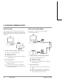
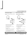
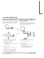
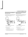
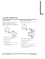
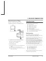
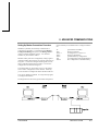
8. ADVANCED COMMUNICATIONS ..........................8-1
Connection Guide.....................................................8-1
Information Guide .....................................................8-7
Procedures Guide...................................................8-13
Bridging Guide........................................................8-19
Dialogs Guide .........................................................8-22
OMRON SYSWIN
III
CONTENTS
9. ADVANCED FUNCTIONS ...................................... 9-1
Function Plan Editor ................................................. 9-1
Importing a Project From Disk.................................. 9-2
Maintaining Libraries ................................................ 9-2
Templates................................................................. 9-3
Producing EPROMs ................................................. 9-4
Saving to PMF File Format....................................... 9-4
Converting Projects From Other Packages.............. 9-5
10. CONFIGURING THE ENVIRONMENT ............... 10-1
Global Preferences - Ladder Diagram /
Function Plan ......................................................... 10-1
Global Preferences - Data Display ......................... 10-5
Global Preferences - Data Trace / Time Chart
Monitoring............................................................... 10-6
.INI File Preferences............................................... 10-6
11. ADVANCED INSTALLATIONS........................... 11-1
Operating System Installation Guide...................... 11-2
Connection Guide................................................... 11-7
Procedure Guide .................................................... 11-9
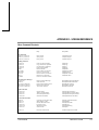
APPENDIX A - SYSWIN FILE TYPES ........................A-1
APPENDIX B - FORMAT SPECIFIERS......................B-1
APPENDIX C - FILE FORMATS .................................C-1
PMF Files ................................................................ C-1
Section Types and Descriptions.............................. C-2
ADR Files ................................................................ C-5
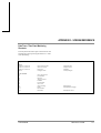
APPENDIX D - SCREEN REFERENCE......................D-1
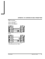
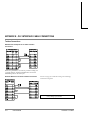
APPENDIX E - PLC INTERFACE CABLE
CONNECTIONS ..........................................................E-1
INDEX
IV
User Manual
OMRON SYSWIN
1 GETTING STARTED WITH SYSWIN
1 GETTING STARTED WITH SYSWIN
Welcome to SYSWIN
The OMRON SYSWIN software is designed for use with
SYSMAC C and CV series Programmable Logic
Controllers (PLCs). It provides a straightforward method of
creating and maintaining programs and testing their
operation, either offline or connected to a PLC.
SYSWIN offers a comprehensive range of facilities for the
PLC programmer, from program editing to full symbolic
and network debugging, including:
■
■
■
■
■
■
■
■
New program creation
Program storage and editing
Uploading and downloading code to a PLC
Program status during execution by PLC
Commenting programs:
Symbolic addresses
Symbolic block and network names
Comments
Maintenance of library files
Printing program and documentation
Conversion from other packages
SYSWIN runs in the Microsoft Windows environment
(version 3.1 or greater) on standard IBM and compatible
486 and Pentium-based desktop computers. SYSWIN is
intuitive to use, and allows the programmer to rapidly
configure a specific project and enter network and program
data. PLC programs can be constructed in either ladder or
function plan format, and previously tested networks can be
recalled from libraries. A special statement list editor allows
PLC programs to be viewed and checked in their mnemonic
format.
User Manual
These features are designed to enable users to easily adapt
PLC programs to changing requirements. Additional
features allow the testing of new networks in a supportive
and safe environment.
The SYSWIN software can communicate with both C and
CV series PLC. Serial communications with the PLC can be
through RS-232C or RS-422 serial interfaces with or
without a modem. Network Service Boards can be used in
the PC to attach to the PLCs using SYSMAC-LINK or
SYSMAC-NET networking.
Communications are handled transparently, leaving the
programmer free to focus on the coding aspects of a
particular PLC project.
NOTE!
It is very important that you register your copy
of the SYSWIN software with your local
OMRON Sales Office, in order to qualify for
technical support. OMRON is not able to help
you unless you have registered.
OMRON SYSWIN
1-1
1 GETTING STARTED WITH SYSWIN
Contacting Technical Support
Licence Registration Information
If you follow the installation instructions for the copy
protection system in this chapter and in the Advanced
Installations chapter you should not encounter any
difficulties. However, if you have a problem, then contact
Customer Services.
SYSWIN V3.4 takes advantage of a different method of
Licence Registration, which replaces the Software Token
and Hardlock (Dongle), which were used on previous
versions.
If you have a problem, it is important that you check that it
does not relate to a fault outside SYSWIN. It is essential
that you check the following:
■
■
■
■
The PC is working correctly
The PLC is working correctly
The communications system is set up correctly
The errors are cleared in the PLC
When you need to contact Customer Services, fill in the
details in the form below. A clear and concise description of
the problem is required, together with the exact text of any
error messages.
On the back of the CD-ROM box, and incorporated in the
label of Diskette 1, is a “Licence Number”.
e.g. 11111-22222-33333-44444-55555
You will be asked to enter this during installation of the
software. The number must be entered exactly as it is
printed.
After installation of the software, a “Registration Number”
is displayed in the software information under the “Help”
dropdown menu.
e.g. aaa-bbb-ccc-ddd-eee
When the “Software Registration Card” is filled in, both
the “Licence Number” and the “Registration Number”
are required. Support for your software may not be
available if it is not registered.
Version number of SYSWIN
Licence Number of software
Registration Number of software
Operating system and version number
If an existing Token or Hardlock are present on a PC, and
SYSWIN is installed over a previous version, you will not
be asked to enter the licence number. After installation a
“Licence Number” can be entered by selecting “Activate
SYSWIN” from the “Help” dropdown menu.
PLC type, model and CPU details
Type of communications in use
Serial
SYSMAC-LINK
SYSMAC-NET
Controller Link
Ethernet
1-2
User Manual
OMRON SYSWIN
1 GETTING STARTED WITH SYSWIN
About this Manual
This User Manual will help you to get started with
SYSWIN, by describing the software installation and
computer configuration, and by leading you through the
basics of SYSWIN programming. It also provides a detailed
reference for all of the on-screen SYSWIN functions.
Throughout this manual, it is assumed that you have a
working knowledge of Microsoft Windows, and know how
to:
■
■
Separate OMRON manuals describe the PLC programming
structure and instruction set in detail. Some small example
programs are included with the SYSWIN software, to
demonstrate some of the most commonly used features, and
if you are new to PLC programming, you can work through
these to familiarise yourself with the software.
SYSWIN comes with a comprehensive context-sensitive
online help system, which is designed to complement this
manual, and provide a quick reference at any point in the
SYSWIN application when the manual is not to hand. This
general help system allows you to obtain progressively more
information about any topic by selecting keywords within
the descriptive text. In addition, quick help is provided for
all PLC instructions.
■
■
■
■
Use the keyboard and mouse
Select options from Windows menus
Operate dialog boxes
Locate, open and save data files
Edit, cut and paste text
Use the Program Manager or taskbar
If you have not used Windows before, it is recommended
that you spend some time working with it using the
Microsoft documentation, before using SYSWIN.
This introductory section deals with several important
aspects of installing and setting up SYSWIN. We
recommend that you read the entire section, especially the
notes on copy protection, before installing the software.
Manual Conventions
Special Symbols
For quick reference on how to do certain tasks, instruction
sequences are in bold type and arrowed (for example ➧ Click on
the OK button).
Words in bold capitals (for example: File|Open) refer to commands
in the SYSWIN menus.
Words in italics (for example: Save Program) are used for options
such as check boxes and buttons in dialogs.
Keyboard combinations are indicated by the key names to be
pressed together, for example Shift+F6.
The ➧ character points to an instruction
User Manual
Special instructions for C series PLCs
Special instructions for CV series PLCs
OMRON SYSWIN
1-3
1 GETTING STARTED WITH SYSWIN
SYSWIN Features
This new version of SYSWIN V3.4 offers increased
functionality for the creation and testing of PLC programs
and increases the range of PLCs it supports.
New features in SYSWIN V3.4:
■
■
Features in SYSWIN V3.4
■
■
■
■
■
■
■
■
■
■
■
■
■
■
■
■
■
1-4
Support for the SYSMAC ALPHA PLCs with 3
digit Expansion Functions
Controller Link Protocol Support
Communications with C-series PLCs using
Ethernet via the PCMCIA interface
Communications with a CV-series PLC using
Ethernet
Communications with a PLC via a C200H
Bridge using SYSLINK
Import and export of data between SYSMAC-CDM
and SYSMAC-SCS
CV Memory Card support
Error history log
Project password protection
Program Password protection
Unit Setup
Advanced Installations
Support for updates to C200HX(CPU65 and
CPU85)
Additional PLC set up for C Series PLCs
Additional CV I/O Table support
C Series I/O Table support
Memory Card Support for CV Series PLCs to
allow for partial download
User Manual
Support for the CQM1H PLC type
Additional PLC setup support: High Speed Counter
Settings for CPM1, CPM1A, CQM1, and CPM2
PLC types; Analogue settings for CQM1 (CPU45
only).
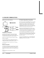
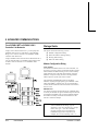
Introduction to Controller Link
SYSWIN additionally supports the Controller Link
network. The Controller Link is an FA network that can
send and receive large data packets flexibly and easily
among the OMRON C200HX/HG/HE PLCs, CV series
PLCs and IBM PC/AT or compatible computers.
The Controller Link supports data links that enable data
sharing and a message service that enables sending and
receiving data when required. Data link areas can be freely
set to create a flexible data link system and effectively use
data areas.
The network is connected using shielded twisted-pair cable,
and high-volume data transmissions at high speed enable
construction of a wide range of networks, from low level
systems to high.
OMRON SYSWIN
1 GETTING STARTED WITH SYSWIN
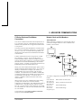
System Requirements
SYSWIN operates on IBM and compatible personal
computers with 80486 or better central processors,
including Pentiums. It should be possible to fully install
SYSWIN on any computer that can run Windows 3.1
software.
The following configuration is recommended as a minimum
system for running SYSWIN effectively:
It is possible to run SYSWIN in CPM1 or Demonstration
mode on any machine that can run Windows software.
If you intend to connect a PLC to the computer for
executing program code and testing, you will require:
■
■
■
■
■
■
■
■
50 MHz 80486 or better CPU, running in enhanced
mode (90 MHz Pentium Processor is
recommended)
At least 8 Mbytes RAM
(16 Mbytes RAM recommended or 32 Mbytes for
Microsoft Windows NT users)
Hard disk storage with at least 10 Mbytes of free
space
VGA or better display system (800 x 600 SVGA or
higher resolution is recommended)
Microsoft Windows 3.1 or higher (Microsoft
Windows 3.11 for Workgroups is recommended)
Mouse
■
■
■
■
Refer to the appropriate hardware system manuals for full
information about connecting and configuring these devices
for your environment. The Advanced Communications
chapter in this manual provides detailed guidance on how to
use SYSWIN for setting up communications. General
information about cabling requirements is given in
Appendix E.
NOTE!
User Manual
RS-232C connection via a standard serial port on
the computer (COM1 etc.), or
RS-422 connection, or
SYSMAC-LINK Network Service Board, or
SYSMAC-NET Network Service Board, or
Controller Link Service Board, or
Ethernet
Windows 3.1 is not compatible with Ethernet
connections unless this service is provided by a
third party package
OMRON SYSWIN
1-5
1 GETTING STARTED WITH SYSWIN
Token Copy Protection
A copy protection mechanism within SYSWIN prevents
illegal use of the software by locking it to a specific hard
disk. The mechanism consists of an operation token, which
must be installed on your system before you use the
software. When SYSWIN is running, it looks for an
operation token, and runs in demonstration mode if it is not
found.
PLEASE READ THIS SECTION CAREFULLY! There are
some important points to note about this copy protection
system and how it might affect your computer.
Installation
If you are installing on a non-standard configuration, that is,
not using either Windows 3.1, Windows 3.11, Windows 95,
Windows 98 or Windows NT , you should read the
Advanced Installations chapter before attempting to install
the operation token.
When you install the operation token that protects your
software, certain files are created on your system that are
not normally visible. It is important that these hidden files
are not moved or deleted. If they are, the operation token
will be damaged, and SYSWIN will not work.
If you ever see the names of the hidden files on your screen,
be careful: you may be about to invalidate your valuable
SYSWIN software!
Restrictions
Your operation token must be transferred back to the master
diskette, for example, if you need to move SYSWIN to a
different computer, or in certain other situations. The token
can only be transferred to or from an operation token
diskette. You cannot install the token to a RAM disk.
System Backup
Most backup utilities do not touch the hidden files created
by the protection mechanism. However, some utilities allow
you to backup and restore hidden files. This option should
not normally be used, because it would cause the protection
mechanism to consider the token invalid. The hidden files
used by the protection mechanism do not have the Archive
file attribute set, so it may be possible to restrict a backup to
files with this attribute set.
File Maintenance
Some file management utilities (for example: Xtree, and
Norton Utilities) list hidden files, and can move them to
other directories, or remove them from the system. Using
this type of software, you may delete the SYSWIN copy
protection files accidentally. If any software mentions these
files during a maintenance operation that removes files,
immediately STOP what you are doing, and move the token
back to the SYSWIN master token diskette, using the Token
Mover. Re-install the token after all maintenance has been
done.
Disk Cache Operation
Certain disk caching software interferes with the installation
of SYSWIN, and should be disabled temporarily during the
installation process. The /d option of Multisoft
Corporation’s PC-Kwik utility should be disabled, for
example. HyperCache has a non-standard option for
accessing diskettes, which should also be disabled during
installation.
1-6
User Manual
OMRON SYSWIN
1 GETTING STARTED WITH SYSWIN
Disk Compression
The copy protection mechanism is compatible with disks
that have been compressed with programs such as
SuperStor, Stacker, DoubleSpace and DriveSpace.
However, SYSWIN must be moved back to the master
diskette when installing any of these compression systems,
as mentioned in their manuals. Failure to do so can cause
the protection mechanism to consider the token invalid.
Disk Defragmenters
SYSWIN’s copy protection mechanism is compatible with
and not affected by disk defragmenters such as Central
Point’s Compress, Digital Research’s Diskopt, Stac’s
Sdefrag and Microsoft’s Defrag.
Backing Up SYSWIN Token Diskettes
The token diskettes each contain a ‘fingerprint,’ which is
written to a non-standard track. This prevents them from
being copied, even by advanced disk copying programs.
You cannot, therefore, copy these diskettes for backup
purposes. If the masters become damaged or lost, you must
contact Customer Services for a replacement.
The SYSWIN program diskettes can be backed up,
however, to allow the masters to be stored in a safe place.
NOTE!
If you are in any doubt about whether any of the
actions you may perform could cause you to
lose tokens, move the token back to the token
disk.
User Manual
OMRON SYSWIN
1-7
1 GETTING STARTED WITH SYSWIN
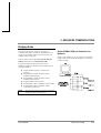
Installation
Installing the SYSWIN Software
This section deals with the installation of SYSWIN on a
standard workstation. For installations related non-standard
workstations please refer to Chapter 11.
The SYSWIN software is supplied on CD-ROM or on highdensity 3.5” diskettes, and is installed easily from within
Windows.
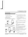
Installing from CD-ROM
Start Windows and insert the SYSWIN CD-ROM in the CD
drive. If Autorun is enabled (Microsoft Windows 95,
Windows 98 or Windows NT only), the setup program
starts automatically. The setup program can be started
manually, by following the instructions in the
README.TXT in the root directory of the CD.
Installing from Floppy Disk
Start Windows and insert SYSWIN Program Diskette #1 in
a suitable diskette drive (our example uses Drive A:). To
install SYSWIN:
➧
Launch the Run dialog
Choose Run... from the Start button from the taskbar
(Windows 95, Windows 98 or Windows NT only) or
from the Program Manager File menu (Windows 3.1 or
Windows 3.11 for Workgroups only). The Run dialog
appears.
➧
Enter the installation command line
Type the diskette drive letter and the SYSWIN Setup
program (for example: A:\SETUP).
➧
Start the Setup program
Click on the OK button. The installation begins.
1-8
User Manual
Further dialogs appear during the installation:
■
Select your desired language for SYSWIN
operation.
■
Enter a path name under which to store the
SYSWIN program files.
■
Select the operation mode as instructed. To fully
activate SYSWIN type in the Licence Number
exactly as shown on the CD-ROM or Diskette. This
dialog is not shown if SYSWIN has already been
fully activated with a token or valid Licence
Number.
Once these are completed, the appropriate files are copied to
your hard drive or the network drive. If necessary, you are
prompted to insert other Program Diskettes when the
software requires it.
SYSWIN V3.4 is fully activated by entering the Licence
Number shown on the CD-ROM or Diskette. SYSWIN
V3.4 can also be fully activated using a token or dongle
from previous version of SYSWIN. For details on using
tokens and dongles, consult the original documentation
shipped with the previous version, and chapter 11 of this
manual.
OMRON SYSWIN
1 GETTING STARTED WITH SYSWIN
Starting SYSWIN
Initial Screen
After the software installation, a new group window for
SYSWIN is created. The software is ready to run, and can
be started by double-clicking on the SYSWIN icon.
If the default preferences have been used, the Automatically
connect to the PLC facility will be set and SYSWIN starts
by checking that the selected communications port is
available. It then attempts to connect to the PLC. If the port
is not available it displays an error message but still
continues.
User Manual
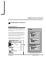
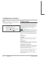
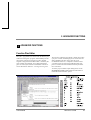
When SYSWIN first starts up, it displays a window similar
to the one shown below. The SYSWIN window offers many
features to ease the process of programming, using the
mouse or keyboard or both. You can configure the display
for any size monitor so that you have as much or as little
information as you need, using options from the
Preferences menu (see Chapter 10). Any changes you make
are saved in the SYSWIN.INI file and are restored next time
you run SYSWIN.
Use this section to familiarise yourself with the layout of the
SYSWIN display, and to set it up as you desire for
programming.
OMRON SYSWIN
1-9
1 GETTING STARTED WITH SYSWIN
Configuring the SYSWIN
Environment
SYSWIN is supplied with default settings that are suitable
for the first time user and there is no requirement for these
to be changed when starting the system. These are global
settings and apply to all projects. These settings, for the
Drawing, Window, Editing and Options, are listed in
Configuring the Environment chapter where all the options
are described. All settings may be viewed by selecting
Preferences from the Menu Bar and selecting the
appropriate item.
Project Preferences, which are local settings for each
project, are discussed in the Working with PLC Projects
chapter and are detailed in the Advanced Projects chapter.
SYSWIN Help System
SYSWIN comes with a detailed context-sensitive help
system. At any time while using the software, you can get
help on the particular point at which you are working, or on
general aspects of SYSWIN. This system is intended to
complement the manual, by providing online reference to
specific functions of the software and how to use them. The
manual is designed to provide more tutorial information and
discuss the various facilities offered by SYSWIN.
Three levels of help are provided in the software: General
Help, for dialogs, messages and menus; Quick Reference,
for programming reference; Instant Help, providing brief
descriptions of commonly used commands.
= GENERAL HELP
General help is obtained by pressing the F1 key or by
selecting an option from the Help menu. This provides
descriptive help on SYSWIN menus and dialogs, as well as
guidance on messages. It can be used at any point in the
software, to take you straight to the topic on which you need
help. The Help menu can be accessed from the main screen
editors, and is best used when you are browsing for help on
the use of SYSWIN.
+
= QUICK REFERENCE
Detailed help on programming elements - functions, timers
and counters, editing and function selection dialogs - can be
obtained by pressing Ctrl+F1 while the desired element is
highlighted. This is termed Quick Reference, since it
displays a summary of the necessary programming
information for any specific item.
If there is not a valid instruction highlighted then Quick
Reference starts up on the contents page and allows you to
click on any item to have help information displayed.
In the Statement List Editor Ctrl+F1 can also be used in the
same way if you place the cursor over an instruction.
1-10
User Manual
OMRON SYSWIN
1 GETTING STARTED WITH SYSWIN
When the bubble help facility (see the Configuring the
Environment chapter) is switched on, a brief description of
each button is displayed when the cursor is positioned over
it for a few seconds.
Status Bar
There is a general status bar at the bottom of the SYSWIN
screen. This provides several helpful pieces of information
while programming:
Instant Help
A brief message appears in the Status
Bar as menu commands and buttons are
selected. This field normally shows the
current block and network information.
Step Number
This is the step number of the first
instruction in the network.
Cursor position
The point in the ladder program where
the cursor is currently located.
Online Edit
status
The online status.
PLC mode
When connected to a PLC, this shows
the current PLC mode. Connection
errors are also displayed here.
PLC scan time
This field is only shown when the PLC
monitoring is active, and indicates the
scan time for the currently executing
program.
The SYSWIN status bar can be enabled and disabled with
the Preferences|Window dialog.
User Manual
OMRON SYSWIN
1-11
2 WORKING WITH PLC PROJECTS
2 WORKING WITH PLC PROJECTS
Program Structure
Although it is possible to create a program that consists of a
simple series of networks, SYSWIN encourages you to
break down a program into groups of networks, which form
functional blocks.
The concept of programming in blocks is designed not only
to make it easier for you to work through a program, by
splitting it into manageable chunks, but also to maintain the
program after it has been in use for a while. Programming in
blocks also eases the process of creating library modules
that can be incorporated into future programs.
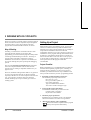
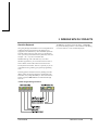
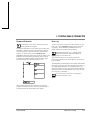
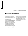
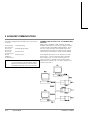
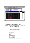
SYSWIN encourages the creation of groups of networks
within blocks, again promoting the concept of working in a
structured manner, as shown in this example:
Typical SYSWIN program hierarchy
User Manual
OMRON SYSWIN
2-1
2 WORKING WITH PLC PROJECTS
With CV series PLCs, interrupt routines are held in separate
blocks, and main blocks are sequential and joined together.
For both C and CV series, the last block in the main
program must contain the END instruction, as normal.
Way of Working
Normally you would not be connected to the PLC when
preparing the main structure of a program. After
programming you would check the program carefully before
connecting and downloading it to the PLC. Checking of
program syntax and validity of functions is done by
SYSWIN at various times as a protective mechanism, but
any logical checking that you do speeds up the debugging
process.
The use of the Project|Program Check feature described
later in this chapter should be noted to ensure that the
program you are creating is compatible with the PLC you
propose to use.
However, SYSWIN’s editing features make it very practical
for you to program more interactively while connected,
especially if the PLC has no critical outputs connected. This
way, your program is verified as each new network is
entered, and the project is kept constantly up to date as a
working system.
2-2
User Manual
Setting Up a Project
When planning a PLC programming project, various items
need to be considered and set up within SYSWIN before
beginning to lay down program instructions. For example, it
is important for SYSWIN to know the model and
configuration of the PLC you wish to program, so that it can
establish the correct program checking and communications
for that PLC. Programming should, wherever possible, be
done for the PLC that is to be used. Once set for a project, it
is not advisable to change the PLC, and preparation of an
initial specification for the program is therefore
recommended.
Project Checklist
Before programming, it is recommended that you make up a
checklist of the important program aspects, including its
structure and PLC parameters. To start a new project in
SYSWIN, you should follow these steps in addition to the
basic procedure outlined in your PLC programming manual:
➧
Determine essential parameters of the PLC
The SYSWIN project setup needs to know:
PLC series (C or CV)
PLC type (C200H, CQM1, etc.)
CPU (where applicable)
Type of communications interface
Your choice of editor and project type.
➧
Assign specific project information
Text information should be provided at least for:
Company name or originator
Project and version number.
➧
Check the project preferences
Determine how you want the project to be displayed,
and how the statement list code is to be generated.
➧
Allocate PLC memory (where applicable)
Work out the balance required between program
memory and expansion data memory.
OMRON SYSWIN
2 WORKING WITH PLC PROJECTS
➧
Establish the PLC setup parameters
Configure the parameters necessary for the desired way
of running the PLC. Some C Series PLCs do not
support this function.
➧
Create the appropriate I/O table
List all I/O devices and addresses related to them. Some
C Series PLCs do not support this function.
➧
Create a basic structure for the program
Note how you plan to group functional networks to
make up program blocks (for example: startup, control,
shutdown).
➧
Decide how to input and edit the program
SYSWIN offers two main methods of working on a
program: ladder diagram and function plan. The
Statement List Editor allows you to view and check
programs at the instruction level, once a diagram has
been created.
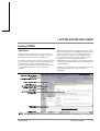
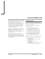
Project Setup
This dialog, accessed with the Project|Project Setup
command, establishes the PLC type, so that SYSWIN can
perform proper checks while you work. It also appears
automatically when you select the File|New command.
There are no defaults for the Project Setup, however,
features are preselected by SYSWIN to give you a starting
point for a project. The Advanced Projects chapter gives
details of all settings that can be selected for the project, but
the following are the initial settings made by SYSWIN.
Series:
Editor:
Project Type:
PLC Type:
Interface:
Bridge Option:
Modem Option:
Coding Option:
C
Ladder
Program
Model
CPM1/CPM1A
CPU
All
Serial Communications
Direct
Local
SYSMAC-WAY
Accepting these settings allows you to start a project, but it
is important to ensure that they match with the PLC and the
Communications method that will be used.
Further information on the options is available in the
Advanced Projects and the Advanced Communications
chapters.
NOTE!
While you can switch between ladder and
function plan editing as you work, it is strongly
recommended that you choose one method and
continue with it for best progress.
User Manual
OMRON SYSWIN
2-3
2 WORKING WITH PLC PROJECTS
Project Information
Creating Ladder Programs
Though not essential when starting, it is good practice to set
up the project front page information before programming.
This information is printed when the front page option is
selected at printing time, and can be viewed any time to
verify that you are working on the correct project. It can be
changed at any time without affecting the program.
This section describes in a tutorial style the process of
preparing ladder programs with SYSWIN, and how to use
the various tools to improve your productivity. SYSWIN
offers many methods of working with its tools: you can use
either the mouse or the keyboard to prepare a program, and
experimentation with both is worthwhile if you are new to
this software. In general, instructions here are given for
keyboard usage.
Company
Insert your company or organisation name here.
Plant
The site where the program is to operate, or the equipment
with which the PLC is to be attached.
Project
A name for the overall project. This could include the PLC
type and model number for completeness.
Version
Current version of the software. This should be updated
every time the program is changed after it has been first
released. Until the program has been tested and debugged, it
should be clearly indicated as unfinished.
Use the File|New project command to start up a new
project. The Project Setup dialog appears, to enable you to
set up the basic parameters as described in the previous
section. You are then returned to the programming
workspace, ready to input instructions into the first network.
The example program that is used in this section is for a
C200H PLC. If you wish to work through the example,
select this PLC type and model in the Project Setup dialog.
Promotion
This field can contain a release number or date, indicating
when the program was issued and went live, or be used as a
comment field.
2-4
User Manual
OMRON SYSWIN
2 WORKING WITH PLC PROJECTS
About the Keyboard
Navigating through the SYSWIN screen is straightforward
with the keyboard, using function and editing keys as
appropriate. The function keys select SYSWIN operations
from the toolbar at the top of the screen. For the drawing
tools, you use keys that look like the symbol they draw, for
example - the ‘-’ key for a horizontal short.
The Enter key normally accepts the dialog. The Escape
key closes the dialog if there is a Close button on the dialog,
or cancels if there is a Cancel button displayed.
SYSWIN dialogs work in the same way as in other
Windows applications: you can use the mouse to select a
field or button, and to make selections from list boxes.
The keyboard can be faster, however, especially if you are
in the habit of using it during your general programming
work.
Selecting options and fields is done by holding down the
Alt key while pressing the letter that is underlined in the
field name, or by using the Tab key to move from field to
field in sequence. Shift+Tab moves backwards through
each one.
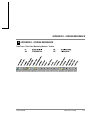
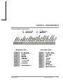
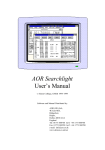
Toolbar Programming Functions
User Manual
OMRON SYSWIN
2-5
2 WORKING WITH PLC PROJECTS
Ladder Programming Workspace
The main area of the SYSWIN screen is devoted to the
ladder program display, as a window covering part of the
total programming workspace. To view a larger portion of
the workspace, you can use Preferences|Overview Mode
command - selecting this same command again switches
back to normal mode.
When first running SYSWIN, or opening a program, you
will always see the lefthand ‘rail’, from which ladder
program networks always begin. A righthand rail exists in
the workspace, at its extreme right, but this is normally off
the screen. When you complete a network, outputs are
drawn showing a small vertical bar to indicate the right rail.
This saves having to scroll the display to see the righthand
side of your networks.
Navigating Networks
The currently selected network is generally displayed at the
top left of the workspace window. The lefthand side of the
power rail is highlighted and the program scrolls as you
move up and down between networks. SYSWIN has a
keyboard interface that allows the Up and Down arrow keys
to roll up and down between networks. PageUp and
PageDown keys scroll the screen by full pages. The
Block|Insert network command (Alt+Insert) enables you
to create a new network, above or below the selected one.
Using the mouse, double-clicking on the left side of the
current network bar, if visible, inserts a new network above
it.
Within a network, the current position is indicated by a
highlighted rectangular block, called the cursor. As you
move around a network, using the arrow keys, the cursor
moves with you. You can go directly to any point in the
program by clicking the mouse on the desired location. The
cursor is actually highlighting the element or space at that
point, and if you enter an element, it replaces the one
displayed. To insert elements between others, you must first
use the Edit|Insert row or Edit|Insert column command
(Alt+Down and Alt+Right) to create a space into which the
new element can be entered.
NOTE!
2-6
Within a network it is possible to create more
space at the bottom of the network by pressing
the space bar as many times as necessary.
User Manual
You can place elements anywhere within the workspace of a
network, but the network is not considered complete until
you link elements together. If a network check is
satisfactory, the network is automatically redrawn and tidied
up, bringing everything to the left rail, with the minimum
distance between each element. A network is checked when
you move to or insert a network after an edit, when you
change any of the PLC parameters, when you select the
Statement List Editor, and at other times when SYSWIN
requires a network to be complete before continuing. To
force a check at any time, press Alt+Enter or Shift+F8.
The maximum network size in SYSWIN is 100 rows by 25
columns.
OMRON SYSWIN
2 WORKING WITH PLC PROJECTS
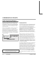
Creating a Network
Bearing in mind that individual networks should be kept as
simple as is practical, they can be entered rapidly. In the
simple example below, there are three elements in the first
network. The elements are placed in sequence, working
from left to right, following these keystrokes (the function
key equivalents can be used if preferred):
➧
Press the ‘"’ (double quote) key to place an open
contact
The Contact Dialog appears, to allow you to
enter more information.
➧
Enter ‘253.13’ as the address, then press Enter
The address identification is displayed above the
symbol in the program.
➧
Press the ‘"’ (double quote) key again to place
another contact
The Contact Dialog appears again.
➧
Enter ‘200’ as the address, then press Enter
The symbol is displayed with its expanded address
shown as 2.00. Since it is an output, it has a righthand
‘rail’ attached. This network is now complete.
➧
Press Alt+S, to move to the address Symbol field
Enter a symbolic name for this output, then press Enter.
The cursor returns to the network and shows the name
below the output.
➧
Press Alt+Enter to check the network
The network is redrawn. Notice how it has been
compacted to eliminate the redundant horizontal
lines that were entered.
NOTE!
Keys used together with Alt and Ctrl keys may
be different for implementations in different
languages.
The key points to note from this small exercise are:
➧
Enter ‘HR1’ as the address, then press Enter
The address is displayed as before. Notice that it is
expanded into its full bit format - HR00.01.
■
■
■
➧
Press ‘-’ two or three times
The connecting horizontal line moves to the
right.
➧
Press ‘O’ to place an output
The Output Dialog appears.
■
Simple keystrokes are used to place elements
Addresses can be entered in abbreviated form
Redundancy is automatically removed on check
Symbolic names can be entered later if desired,
although it is good practice to create them as the
program is entered.
About Addresses
It is important to use the standard form of addresses in
SYSWIN. Addresses may have two components - a channel
number and a bit number - and these should be separated by
a dot. In the example above, the address ‘200’ has been
interpreted by SYSWIN as ‘2.00’. If we had meant to use
bit zero at address 200, it would have been necessary to
enter it as ‘20000’ or (preferably) ‘200.00’. Note that in the
second step of the example, we used ‘253.13’ to illustrate
this, where we mean bit 13 in channel 253.
User Manual
OMRON SYSWIN
2-7
2 WORKING WITH PLC PROJECTS
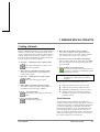
Adding to a Network
Any network can be expanded with simple editing
functions. For example, to create a simple OR instruction at
the start of the network just entered:
➧
Position the cursor on the leftmost element
Use the arrow keys to move it there.
➧
Press the space bar to create a new element line
The network expands downward, and the cursor is at the
left rail. Press the down arrow and you are ready to
insert a new element.
➧
Press the ‘"’ (double quote) key to place an open
contact
The Contact Dialog appears as before.
➧
Enter ‘HR0’ as the address, then press Enter
The window closes and the address is expanded to
HR00.00 above the drawn symbol.
➧
Press the Up arrow to move up to the top line
The cursor is positioned ready to insert a new vertical
connecting line. Note that the line is inserted on the left
side of the cursor.
➧
To view the actual instructions generated by this
network, use the Statement List Editor. Select the
editor via the Editors menu, or by clicking on its button on
the toolbar (Ctrl+F8). The instructions are listed in
mnemonic format, and can be edited in the normal way. If
everything is correct, then the ladder is redrawn; if errors
are detected, then you are warned. The Statement List
Editor is described in detail later in this chapter.
Adding Comments to a Network
It is recommended that you add comments to
networks as they are written, so that it is easier to
understand their functions when reviewing the program
later. You use the Network Symbol Editor to name a
network and add suitable comments. Start the editor by
selecting it from the Editors menu, by selecting the
Network Symbol Editor button on the toolbar (Ctrl+F7), or
by simply double-clicking the mouse on the network
comment bar (if it is visible).
In the Network Symbol Editor, a network can be given a
name up to 15 characters long, and up to 30,000 characters
of text as a description or comment. Note that text can be
wrapped to fit onto the display screen.
The Network Symbol Editor is described in more detail later
in this chapter.
Press ‘|’ or ‘!’ to insert a vertical connecting line
The first and second lines are now connected.
The network is now complete as everything is connected.
Press Alt+Enter to check it is valid and to redraw the
network.
2-8
User Manual
OMRON SYSWIN
2 WORKING WITH PLC PROJECTS
Adding More Networks
After the initial entry of a program, you usually
need to add further networks. Use the Block|Insert
network command to open a new network (the preferred
shortcut is Alt+Insert). Alternatively, select the button on
the toolbar (Shift+F6). You are asked to specify whether
you want the new network to be above or below the
currently selected one.
You are always working within a single block, and
while in that block you have access only to the
networks it contains. To move to another block of networks,
you must use the Block|Select block / network command,
accessible with a toolbar button (Shift+F5). This dialog
allows you to go directly to a specific block or network
anywhere in the program - it also provides a search-byname facility for networks.
NOTE!
A new network area appears in the workspace, and you can
begin entering the new network immediately.
NOTE!
Individual networks must be entered separately,
and all elements must be joined together in a
network.
You can also switch between blocks by using
the Ctrl+Shift+PageUp and
Ctrl+Shift+PageDown keys.
A detailed description of the Block/Network Manager is
provided later in this section.
Entering Functions, Timers and Counters
Blocks and Networks
At the top of the program that you have entered, there is a
block header above the first network. This is automatically
created by SYSWIN when a new program is started.
Although a program can be produced within a single block,
it is strongly recommended that you break up the program
into small manageable groups of networks within separate
blocks.
You use the Block/Network Manager to form groups of
networks, and to provide names and comments for the
blocks you have created. The Block Symbol Editor is
started through the Editors menu, or through the
Block|Block / network manager, which has its own toolbar
button (Ctrl+F5). Double-clicking on the block header bar
also opens the Block Symbol editor.
All ladder programs use functions in addition to the basic
instructions, and most use timers and counters. These are
entered in much the same way as symbols, but because most
of them require data parameters on which to operate, the
process involves different dialogs.
Functions
SYSWIN uses your setting of the PLC type, together with
your function mapping parameters (where they apply) to
determine which functions are available to use. When a
function is selected, a dialog box is displayed requesting the
necessary data.
If you know which function you wish to insert in a network,
the easiest way to enter it is to use the ‘F’ key. This displays
the function dialog box, and you can type in the name or
number of the function.
Block information is entered in the same way as with the
Network Symbol Editor, and once accepted, it is displayed
on the block header in the ladder workspace.
User Manual
OMRON SYSWIN
2-9
2 WORKING WITH PLC PROJECTS
SYSWIN follows your typing, and as soon as it identifies a
valid function, its complete name is displayed for you, and
the parameter fields are displayed. When entering a function
that may be ambiguous, enter a space after the last character
(for example: MOV<space> to force identification of a
MOV(21) function, and not a MOVD).
When you are unsure about a function name, press the
Select button. This displays the function group list box and
the functions in the highlighted group. Move the cursor to
the group you require and select the appropriate function
from the list. Exit the selection dialog, and complete the
function parameters. Pressing the Reference button or
Ctrl+F1 displays Quick Reference on any specific function
that is highlighted.
Enter the appropriate values in each data field, using the
Tab key to move between them. SYSWIN validates the data
that you have entered when you accept the dialog. If you
have entered an incorrect parameter, an error message
appears, telling you which one is incorrect, and why.
When a function is drawn, its inputs (and occasionally
output) are indicated by unterminated lines. These need to
be connected to other parts of the network before the
network is complete.
Differentiated Functions
Most functions are available in differentiated and nondifferentiated forms. They are identified by special symbols
in front of the name. When a function can have more than
one form, the dialog provides extra check boxes.
Alternatively, you can use special characters when typing a
function name, and SYSWIN converts the function as
appropriate:
@
%
!
Differentiate UP
Differentiate DOWN
Immediate refresh
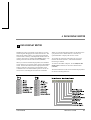
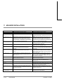
The availability of differentiated functions, contacts and
outputs depends on the PLC type, as shown in the table
here.
2-10
User Manual
PLC Type
Functions
Functions
Outputs
Contacts
Diff Up
Diff Down
Refresh
ü
(SET/RSET only)
ü
ü
ü
ü
ü
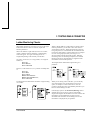
Timers and Counters
Use the ‘T’ key to place a timer, and the ‘C’ key for a
counter. In both cases, a small dialog will request a value
parameter, as well as the necessary timer or counter number.
On the ladder diagram, a timer requires one input execution
condition, while a counter requires two inputs - the
execution condition and a reset.
Using the Function Menu
An alternative way of selecting functions and other ladder
instructions is to use the Function menu. This groups
together similar types of instructions, and for each menu
command, a dialog is displayed which allows you to select
the appropriate item from a list.
This menu is useful in helping to choose the correct
instruction for a network, especially when the detailed PLC
programming manuals are not available. In addition, while
you are in one of these dialogs, selecting an instruction and
pressing Ctrl+F1 brings up Quick Reference on the syntax
and usage of the instruction.
NOTE!
You can use Ctrl+N to Negate, Ctrl+U to
differentiate Up, Ctrl+D to differentiate Down
and Ctrl+I to Immediate Refresh the selected
element.
OMRON SYSWIN
2 WORKING WITH PLC PROJECTS
Editing Networks
Networks can be edited at any time, even while connected
to a PLC, and each edit is verified by SYSWIN as it is
entered. Some of the editing controls can be used to speed
up programming, for example by cutting and pasting
between networks.
Selecting Network Elements
Once a function, timer or counter has been drawn, its
parameters can be changed. To do this, select the instruction
by moving the cursor onto it and press Enter, or doubleclick on the instruction with the mouse. If you double-click
on one of the parameters in the ladder diagram, that one is
highlighted in the editing dialog when it opens.
Once the editing cursor is positioned over an element, a
block of elements can be selected by holding down the Shift
key while using the arrow keys to move around and add to
the block - the highlighted area grows as you do so. Having
selected an area with the Shift key still held down, if you
move back into it with an arrow key, the appropriate
elements are de-selected. With the mouse, it is necessary
only to click and drag from a start point to select and deselect elements. In all cases, the selection remains active
until you move the editing cursor with the mouse or the
keyboard arrow keys.
Using the Address Bar
The addresses, symbol names and comments assigned to
each symbol can be changed easily. The quickest way to add
symbolic information is to use Alt+S to move to the Symbol
field in the address bar at the bottom of the screen. After
entering a name, use the Tab key to move to the Comment
field. After entering a comment, the Enter key stores the
symbol and takes you back into the ladder diagram.
NOTE!
Keys used with Alt and Ctrl keys may be
different in implementations in other languages.
Alternatively, you can use the Tab key to move the editing
cursor out of the diagram to the address bar. Then you can
just tab through each of the fields back into the diagram.
You can use Shift+Tab to move in the opposite direction.
While the editing cursor is outside the ladder diagram, the
cursor over the element turns grey. It returns to black when
you move the cursor back into the ladder diagram.
For global editing and manipulation of symbol information,
use the Address Symbol Editor as described later in this
chapter.
Manipulation of elements and networks is done with a wide
range of editing commands. These allow you to select, copy,
move and delete elements.
User Manual
To select an element anywhere in the program, use the page
keys or scroll bars to locate the network, and move to the
element with the arrow keys, or just click on it.
If you wish to select a specific path through a network, and
not a simple block, hold down the Control key while
clicking on the items you require. To deselect a path, release
the Control key and click on any of the elements in the
same network.
Deleting Network Elements
A single selected element in a network can be deleted with
the Backspace or Del key, but to delete group selections
you must use the Del key. Note that the Del key deletes
without moving the cursor, while Backspace moves the
cursor to the next element to the left. If you use these
controls to delete the entire contents of a network, the
network is still open (keeping its name and comments), and
you can re-program it.
To delete a network completely, removing it from
its parent block, use the Block|Delete Network
command (Alt+Delete), or click the delete button on the
Toolbar (Shift+F7). Note that once deleted, a network
cannot be restored, using Undo.
OMRON SYSWIN
2-11
2 WORKING WITH PLC PROJECTS
Copying Network Elements
Restoring Networks
Elements and networks can be copied to other parts of a
program, or to another program, with the normal Windows
cut-and-paste facility. For example, to copy part of a
network from one place to another in a program, first select
the section to be copied.
A networks can be restored to its earlier state, regardless of
the number of changes made in the ladder workspace. There
are two types of restore command in SYSWIN:
Use the Edit|Copy command (Ctrl+C), or click on
the copy button on the Toolbar. The selected
elements are copied into the internal clipboard. Now you
can move to another part of the program, or even open a
different program, before pasting the copied elements.
To paste the elements, position the editing cursor at
the point where the elements are to be pasted. If you
are copying an entire network, you need to insert a new
network ready to receive the elements. Use the Edit|Paste
command (Ctrl+V), or click on the paste button on the
Toolbar.
The Edit|Undo command (Ctrl+Z), or its toolbar
button equivalent, restores the current network to
the state it was before the most recent operation.
The undo command can be used repeatedly to step back
through a sequence of operations. Only those operations
that can be reversed are undone.
The Block|Restore network command restores the network
to its most recent state, that is, either when last tested by
SYSWIN, or last opened.
Moving Network Elements
The procedure to move an element or group to another
location in the program is the same as for copying,
described above, except that the Cut command from the
Edit menu (Ctrl+X) is used in place of the Copy command.
The Cut command, and its button equivalent in the
Toolbar, deletes the selected elements from the
current network after making a copy in the internal
clipboard. To insert the selection elsewhere in the program,
use the Paste command (Ctrl+V).
2-12
User Manual
OMRON SYSWIN
2 WORKING WITH PLC PROJECTS
Saving and Loading Projects
Maintaining project files on disk is done in the same way as
in other Windows applications. The File menu provides the
necessary options for working with files, and some of these
are also available as buttons on the SYSWIN toolbar for
convenience.
SYSWIN project files are stored in a dedicated format, and
can be read only by the SYSWIN software. Several types of
file are used, according to the method of programming used
to create a project, and the version of SYSWIN that was
used to create them. Project files are identified by a
filename extension added to the project name, as follows:
Project.SWP
Project.SWL
Project.SWT
Project.SWB
Project.SWN
Project.PRG
SYSWIN 2.x/3.x Program
SYSWIN 2.x/3.x Library
SYSWIN 3.x Template
SYSWIN 2.x/3.x Backup File
SYSWIN 1.x Program
PMD Program
You can save the project at any time. During testing, and
especially when working while connected, it is
recommended that you create copies as the project proceeds,
which allow you to restore a previous version more easily.
However, when a project is saved, the previous version of
the file is renamed to become a backup file (.SWB), so that
you can easily move back one version by copying the
backup into the current file.
Whenever you make changes to a project, SYSWIN
reminds you to save your project if you wish to open
another project, or if you exit from the application.
Saving a Project to Disk
The File|Save project command stores a project on
disk, and if it has already been saved once,
overwrites the file with the latest version. You can use the
toolbar button (Shift+F3) as an alternative to the menu
selection. With a saved project, this option simply updates
the files on disk, with no further prompting.
When you first save a new project, a standard Windows file
save dialog appears, allowing you to locate and name the
file. Follow these steps to save the project:
➧
Locate the directory in which to create the file
Use the Directories and Drives fields to navigate to the
desired location. Any existing files in the directory you
choose are listed, but greyed out.
➧
Enter a name for the project
Select the File Name field, and enter a suitable project
name (up to 8 characters long).
➧
Check the format in which the file is to be saved
The program is saved either as a project file (.SWP), a
library file (.SWL) or as a template file (.SWT)
depending on how it is defined in the Project Setup
dialog.
➧
Click on OK to save the file
Saving a Copy of a Project
The Save project as command, enables you to save the
current project in a new file. It can be used the first time a
project is to be saved or when you want to change the file
name or its location. When selected, it displays the standard
save dialog box, as described above, and you should follow
the same steps to create the new file.
User Manual
OMRON SYSWIN
2-13
2 WORKING WITH PLC PROJECTS
Loading a Project From Disk
Editors
A saved project can be opened for further work with
the File|Open project command (or you can use the
toolbar button - Shift+F2). If a project is already open when
you select this command, you are asked if you wish to save
the current project before proceeding. The Open Project
dialog is similar to the Save Project dialog. Follow these
steps to open the project:
Editors are supplied in SYSWIN to perform functions
additional to the basic Ladder Editing. The following
sections in this Chapter describe those editing functions that
are provided in the Statement List Editor, the Address
Symbol Editor, the Network Symbol Editor, the Block
Network Manager and the Block Symbol Editor.
➧
Locate the directory in which the project resides
Use the Directories and Drives fields to navigate to the
desired location. All existing files in the directory you
choose are listed.
➧
Select the formats you wish to have listed
The List Files of Type field provides a list box showing
formats available for viewing.
➧
Select and open the desired project
Double-click on the name of the file you wish to open,
or click once on it, then click on OK.
Alternatively, if you know the name and location of the
project you wish to open, you can enter its complete
pathname in the File Name field.
When you accept the dialog, the project file is opened and
displayed in the programming workspace. All of the
parameters relating to the project are set automatically.
2-14
User Manual
OMRON SYSWIN
2 WORKING WITH PLC PROJECTS
Statement List Editor
The actual PLC instruction code which underlies any ladder
program can be viewed and edited with the Statement List
Editor. It allows you to verify the contents of networks in
instruction format, and make changes as necessary. You can
use the Statement List Editor to create an entire program,
though the features of SYSWIN encourage a more intuitive
programming method using ladder diagrams. This editor is
intended to enable the viewing and modification of
networks when the need arises.
When entering instructions, you can use upper or lower case
characters. SYSWIN automatically converts to upper case
when the network is next tested. You should separate
instructions from operands with a space or a tab (entered as
Ctrl+Tab), and allow the editor to correctly format the list.
The Statement List Editor is opened with a
command from the Editors menu, or by clicking on
the Statement List Editing button on the Toolbar (Ctrl+F8).
This dialog operates with the ladder display, so that when
you move between networks, the ladder display moves too,
and always shows the same network as selected in the
editor. Use the Previous and Next buttons to step from one
network to the next.
Verifying a Statement List
The Network and Name fields from the current network
header are displayed - the name field can be changed with
the Network Symbol Editor.
Statement List Display
The instruction list can be displayed in either address or
symbolic format, depending on your selection for the
Display option. If you have used the other editors to create
symbol names for addresses, the information displayed here
in Symbol mode makes it easier to follow the instruction
listing. You can only change between display modes when
the instructions are valid.
Editing a Statement List
Instructions are entered as normal text, similar to Notepad.
You can use the Windows cut, copy and paste tools
(Ctrl+X, Ctrl+C and Ctrl+V) in the usual way to edit the
list, and the mouse to select items for copying or deleting.
Ctrl+Z can also be used to undo the last change.
User Manual
While normal instructions can be edited within the ladder
diagram, block programming statements must always be
edited using the Statement List Editor.
Several instructions can be entered in sequence - no
checking of syntax or network completeness is done until
requested. The Test button allows you to verify the list
while staying within the current network. The Next and
Previous buttons at the bottom of the dialog also force a
check, as SYSWIN does not allow you to close the editor or
move to another network without checking the current one.
If an instruction cannot be understood by SYSWIN, that
instruction is highlighted in the list, and you must correct it
before leaving the editor.
Some sequences of instructions may result in
SYSWIN being unable to draw the network. In this
case, you are able to leave the editor, but the ladder diagram
shows a special symbol, replacing the network display, to
show that it cannot be drawn. This situation should be
avoided wherever possible.
There are two situations that cause this to happen:
instructions that cannot be sequenced properly and block
programming instructions. Block programming instructions
cannot be drawn in the ladder diagram, because they
represent sequences of instructions rather than a powerflow
network.
OMRON SYSWIN
2-15
2 WORKING WITH PLC PROJECTS
Restore
Use this button to return the list to its original state when
you entered the editor, or to the last tested version. The
complete list is restored, regardless of the number of
changes you have made.
Browse
This button allows you to choose a symbol or address from
the Address Symbol Editor without leaving the Statement
List Editor.
Close
The Close button forces a network check, and you are
returned to the ladder display, with the network redrawn to
reflect the changed situation.
As described above, any inconsistencies in the network
cause an error to be generated, and although you can
continue and ignore it, it is recommended that it is
thoroughly checked before closing the dialog.
Address Symbol Editor
The addresses used within the program can be given symbol
names to make it easier to read and understand a program.
These names can be entered and edited directly with the
Address Bar at the bottom of the screen at the time when
elements are placed in the network. The Address Symbol
Editor provides a straightforward way of entering this
information as a separate task, allowing you to assign
symbol names to any address.
The Address Symbol Editor is accessed through the
Editors menu, or by clicking on the Address
Symbol Editor button on the Toolbar (Ctrl+F6). The dialog
displays all addresses and symbols that have been created in
the project, and offers several editing facilities. Symbolic
information is displayed at the bottom of the dialog, in the
editing fields.
When you enter the dialog, the Find field is highlighted, so
that you can immediately enter part of an address or symbol
name that you wish to search for.
The list of addresses is given in numeric or symbolic
sequence. You can use the Sort Order options to switch
between them. The page and arrow keys can be used to
locate any address. You can also use the mouse to directly
select an address by clicking on it.
If the editor has been started as a Browser from another
editor, then OK enters the selected address back into the
previous editor.
Store
After editing each address symbol, use the Store button to
save it into the project. When you are editing address
symbols in the bottom section of the dialog, the Enter key
will store the information.
New
Use the New button to add an address and symbol name to
the table. The cursor moves into the Address field, so that
you can enter the number of the address you wish to add.
2-16
User Manual
OMRON SYSWIN
2 WORKING WITH PLC PROJECTS
Find
The Find field allows you to enter a partial or complete
address or symbol name to be found. As you type, addresses
matching that name are searched for in the list and the first
name that matches is highlighted. Then, to edit the name
and comment, just press Enter or click on the Edit button.
Edit
Having highlighted an address, either by searching or by
direct selection, the Edit button takes you into the Symbol
field ready to change the symbol. Alternatively, you can use
the Enter or Tab keys to move to the Symbol field.
Delete
This button deletes the selected entry from the symbol list.
Deleting an entry does not affect the program itself, just the
information associated with an address.
Load
Address Symbol information can be imported from another
SYSWIN project. Use the Load option to open a file and
have the address information automatically brought into the
current program. When the file to load is selected, SYSWIN
gives you three options. The first option is to Merge the file
with the present one overwriting ones with the same name.
The second option Merges the file but does not overwrite
Address Symbols and the third option Loads the file and
replaces all Address Symbols currently loaded.
Scan
This option scans through the program for addresses that
have been used, but which have not had symbols assigned
to them. These are then listed, and you can select each
address in turn to enter the appropriate information in the
Symbol and Comment fields. Note that this option is
available only when the display is sorted by Address.
The current network must have been tested before any new
addresses appear in the list.
Auto
SYSWIN provides the Auto option for adding comments to
sequential addresses. When this is enabled, typing an
address such as HR1, starts the auto-numbering. After you
have entered a symbol and comment, pressing Enter causes
the next unallocated address (for example, HR2) to appear
automatically, ready to be given a symbol.
Save
This button saves the Address Symbol information in .PMF
format via a standard save dialog.
Close
This button closes the dialog - alternatively you can press
the Escape key. Any changes not saved with the Store
button are lost.
Purge
After intensive editing operations, the program may contain
symbolic information which is not attached to any element
of the program. The Purge option scans the program for
unattached symbols, and deletes them from the symbol
table.
The current network must have been tested before any
unused addresses are purged from the list.
User Manual
OMRON SYSWIN
2-17
2 WORKING WITH PLC PROJECTS
Network Symbol Editor
To add comments to networks, you use the Network Symbol
Editor. With this editor, networks can be located and given
a name, and comments can be added. The information is
displayed in the network header, and can be used in place of
the network number during searching operations.
The Network Symbol Editor is accessed through the
Editors menu, or by clicking on the Network
Symbol Editor button on the SYSWIN Toolbar (Ctrl+F7).
A useful shortcut is to double-click on the comment in the
network header bar. This displays the dialog to enter and
change information.
Making Network Groups
When the Show Network Groups option is switched on
(using the Project Preferences), the Network Header display
appears on a ladder workspace only if the network has been
given a name. If the networks below the current one are not
given names, then the networks appear to form a group.
The dialog operates in conjunction with the display. As you
move between networks with the Previous and Next
buttons, the appropriate network is displayed in the
programming workspace, so that you can see which network
you are working on.
The Network Symbol Editor can be started from within the
Block/Network Manager by pressing the Name button.
Restore
Use this button to restore the Name and Comment fields. All
changes done to the current network will be discarded.
Insert and Remove
The Insert and Remove buttons are normally used to realign
comments after a program has been uploaded from a PLC.
The Insert button pushes all the following comments down
by one network. It allows you to open a gap in the network
list to accept a new name and comment. All network names
and comments after the insertion point are shifted down.
The comments on the last network will be pushed off the
end and lost.
The Remove button removes the current Name and
Comment and pulls those below up by one network. The
last network therefore does not have a name and comment.
2-18
User Manual
OMRON SYSWIN
2 WORKING WITH PLC PROJECTS
Block / Network Manager
Using the Block / Network Manager, you can structure and
add comments to PLC programs. The Manager consists of a
main dialog which is used to gather networks into blocks,
and provide access to general block and network
maintenance such as selection, insert, modify and comment.
The Manager is started from the Block menu, or
with its toolbar button (Ctrl+F5). Blocks and
networks are displayed as lists of numbers and names. Note
that the list of networks are only shown for the currently
selected block.
As you move up and down with the arrow keys or the
mouse, the workspace behind changes so that the selected
network is at the top of the window. You can then check
that you are at the correct point in the program. The Name
button then starts either the Block or the Network Symbol
Editor as appropriate. Double-clicking on an item in a list
also starts the editor.
The buttons at the bottom of the dialog perform standard
editing functions on a block or network. They provide a
convenient way of doing globally many of the tasks that can
also be done as you program.
Find
The Find field allows you to enter a partial or complete
network name for searching. As you type, networks
matching that name are looked up in the list and the first
name that matches are highlighted. Then, to edit the name
and comment, press the Name button.
Find Next
This option searches for the next item that matches the
name entered in the Find field.
Insert
A new block or network can be inserted in the program,
above the current position in either list. Either the Block or
Network Symbol editing dialog appears, and you can add
comments to it before entering networks into the program.
User Manual
Name
Allows any block or network name and comment to be
displayed and modified, again by displaying the necessary
dialog.
Delete
This option removes the currently selected block(s) or
network(s) from the program. A warning message is given
before the selection will be deleted. The Del keystroke can
be used as a shortcut for this operation.
Cut, Copy, Paste
These options operate like the standard Windows editing
commands from the Edit menu, and provide a shortcut
mechanism for copying items, moving them, and changing
the sequence of blocks and networks within a program. For
these operations, you can also use the standard keyboard
shortcuts: Ctrl+X (Cut), Ctrl+C (Copy) and Ctrl+V
(Paste).
Load Blocks / Networks
Blocks and networks can be imported from SYSWIN
libraries and other programs. Use the Load option to open a
library file. If the Block side of the dialog box is highlighted
then Load Blocks will appear and if the Network side of the
dialog is highlighted then the Load Networks button is
displayed.
Select this option and the Import Blocks / Networks dialog
is displayed. This gives you the opportunity to select from
the displayed list of blocks or networks. You can change to
another library if necessary by using the Select button. The
selected project blocks or networks are automatically loaded
into the current project.
When the project is opened, the blocks it contains are listed
in the Blocks area of the dialog. To select blocks for
insertion, use the mouse to click on single items, Ctrl+click
to select several, or Shift+click to insert a range or
Shift+End to insert the entire project.
OMRON SYSWIN
2-19
2 WORKING WITH PLC PROJECTS
When inserting networks, you need to press the Load
Networks button. You can then use the same methods as for
blocks to select networks for insertion.
Note that insertion in the project takes place above the
current selection point, and that to add an item to the end, it
is necessary to select the blank line that follows the last item
in a list.
Load Comments
Program comments can be loaded from an existing project
or library file with this button. The standard file open dialog
is displayed, which allows you to locate and open the
appropriate file. Only block and network comments are
imported, and these are added to the current program in the
same sequence as they were originally saved.
If you need to realign the block or network comments use
the Insert or Remove button in the Network Symbol Editor.
Print
The currently selected block(s) or network(s) can be printed
from within this dialog.
Close
This button closes the Block / Network Manager. Pressing
the Escape or Enter keys also closes it.
2-20
User Manual
Block Symbol Editor
While working in the Block / Network Manager, this editor
is started by using the Insert and Name options. When you
are in the ladder workspace, it is selected from the Editors
menu, or double-click on the block header bar.
The Block Symbol Editor displays the current block number
and any information that has been already entered. Use the
Tab key to move between the Name and Comment fields,
and edit them as necessary. The Restore button loses any
changes that have been made.
The Block Type menu is used only with CV series PLCs. It
lists the fixed block types that are used with this series.
The Block Type also serves to avoid possible duplication of
interrupt routines. Note that it is only through using this
dialog that interrupt routines can be changed.
When you accept the dialog, the block name and comments
are displayed in the block header above the first network in
the programming workspace.
OMRON SYSWIN
2 WORKING WITH PLC PROJECTS
Checking the Program
Global Editing - Find and Replace
The Project|Program check option allows you to ensure, at
any stage, that your program is valid. The dialog which is
displayed has several options that can be selected before
executing the check. These may include Subroutines,
Instructions and Interlocks and an Assembly check.
SYSWIN gives you powerful global searching and editing
facilities with the Edit|Find and Edit|Replace commands.
These allow you to scan a program for all occurrences of
any label, address, bit, channel, register or instruction and to
change them globally.
By using the Scope feature you can choose to check the
current network, the current block or all blocks.
Searching for Data
When the options are chosen, press the Execute button and
a report may be displayed. This report contains any errors
which have been found in the program and warnings to be
checked. You can step through the list of errors by moving
the highlight bar in the list box. If you press the Go to
Network button, the Statement List Editor opens and the
line in error will be highlighted. The error can then be
corrected and another error chosen from the report dialog.
If this information needs to be kept, then the Copy button
copies the report to the Windows clipboard to be used by
other programs.
The Close button closes the dialog.
If you wish to look at a program, or part of it, without
making any changes, use the Edit|Find command. The
dialog allows you to narrow the search in several ways.
Similar options exist in the Edit|Replace dialog.
Type
You can search by Address or its symbol name (for
example: ‘AR5.05’ or ‘SwitchOn’), Label (for example:
‘23’) or Instruction (for example: ‘MOV’). The type you
select affects the validity of the information you enter into
the Find fields.
Direction
For searching purposes, the starting point is taken from the
cursor in the current network, and from here you can begin
a search Up or Down the program.
Scope
You can choose to search just the current block or all
blocks. When the Scope is set to All Blocks, Go To Top
moves the start position to the top of the program and
searches Down. When the Scope is set to Current Block, Go
To Top moves to the start of the current block and searches
Down.
Find From / To
Use these fields to specify the range of items that you are
searching for. Enter address symbol names in full for a
successful match. Other data can be partially entered, such
as searching for generic addresses. If you are looking for
only one item, it is not necessary to enter anything in the
Find To field. Neither field is case-sensitive.
User Manual
OMRON SYSWIN
2-21
2 WORKING WITH PLC PROJECTS
Exact Match
In a complex program, you often want to be very specific
about both the name and type of item that you are searching
for. The Exact Match option forces a search only for the
items you have entered in the Find fields. This is
particularly relevant when you wish to replace items, as it is
possible without exact matching to change something
unintentionally.
To help with specifying items to match, the table below
gives examples and notes for each type of item.
Item type
Bit
Channel
Indirect
Const16
Const32
Indexed
Items searched
Bits
Channels &
Bits†
Channels
Channels
Channels
Channels & Bits
Examples
0.00
0
Data Register
Index Register
Label
Channels
Channels
Labels††
Notes:
†
When Exact Matching is NOT used, the
channel part of a bit address would be replaced
with the new channel address: for example,
changing AR2 to AR4 would also change
AR2.05 to AR4.05.
AR5.05
AR5
*DM0
*EM9
#0000
#9999
#00000000
#99999999
IR0, IR1+(+) -(-), IR2 +/1234, IR0 DR1, IR1
DR0
DR2
IR0
IR2
0
99
Replacing Data
The dialog for the Edit|Replace command is similar to that
for Edit|Find, but there are some additional options.
Replace Options
Use the Find Next button to locate the next matching item
from your specification. The appropriate element is
highlighted in the ladder workspace. The Replace button
changes just that element, and you must then use the Find
Next button again to move on. If you are satisfied that the
correct element has been located, and you then want to
make a global change, pressing Replace All changes all
occurrences of that address, from that point to the end of the
Scope.
Prompt Replace
When you select the Replace All option, you can choose to
be prompted each time the specified symbol is found. This
is a safer way of doing global replacements, especially with
complex searches.
Prompt Replace is forced on automatically if you request
Replace All while working connected to the PLC in Online
Edit.
NOTE!
Bit addresses in the Find/Replace dialog must
be entered in the SYSWIN format, using a dot
to separate the channel and bit address. For
example: use ‘253.13’ instead of ‘25313’.
††
A label is the number of a subroutine, as used
in JMP, JME, SBS, and SBM instructions.
1.
Searching for a channel will match channels, bits and
indirect channels: Exact Match will match only channels, for
example, AR2 will only match AR2, and not AR2.05.
2.
Searching Const16 will match Const16 and Const32, if
Const32 values are only 4 digits long, for example, #5555
will match #5555 and #00005555.
Move Symbols
When you select the Move Symbols option, the address
symbol information is moved when the address is first
found and then replaced. For example, if HR05 has an
address symbol ‘Relay1’ and you replace HR05 with HR07
with the Move Symbols option selected, then the ‘Relay1’
address symbol is assigned to HR07.
Examples of matching possibilities
2-22
User Manual
OMRON SYSWIN
2 WORKING WITH PLC PROJECTS
Find
Replace with
NON-EXACT MATCH
AR2
AR4
HR5
LR7
DM0
DM2
HR5-6† HR7
EXACT MATCH
AR2
AR4
HR5
LR7
DM0
DM2
HR5-6† HR7
Notes:
Replaces
AR2 → AR4, AR2.05 → AR4.05
HR5 → LR7, HR5.09 → LR7.09
DM0 → DM2, *DM0 → *DM2
HR5 → HR7, HR6 → HR8
HR6.05 → HR8.05
AR2 → AR4
HR5 → LR7
DM0 → DM2
HR5 → HR7, HR6 → HR8
†
This is called ‘calculated replacement’, where an
offset is calculated from the Find item, and applied to
all items that fit the specified range. In this case, it is
only necessary to specify the start of the range of
items to be replaced.
Examples of address replacement
On-Screen Cross Reference
Select Block|Cross reference command to display the
Address Cross-referencer dialog. Using the Display options,
you can choose to display the list of addresses used within
the current network (Alt+F7) or you can display the
complete list of addresses used within the whole program
(Alt+F8). When you are editing the program in the ladder
editor, you can press Alt+F6 to quickly show the crossreferences for the current address at the cursor.
When an address is highlighted in the Address list, the list
of cross-references is displayed for the selected address. If
you click on a cross-reference, the ladder editor display
moves to the network containing the reference.
Find Address
You can quickly find the references for any address by
typing in the Find Address field. As you type, SYSWIN
highlights the closest matching address in the address list.
When an address is highlighted, the list of references for
that address is displayed.
Previous / Current / Next
If you chose to display the address list for the current
network, you can use the Next and Previous buttons to
change the current network. The Address list is updated for
the new network. If you have changed the current network
by clicking on cross-references, you can update the Address
list by clicking the Current button.
Go To
If you have a cross-reference entry highlighted, you can
close the Address Cross-Referencer and edit the current
network using the ladder editor by pressing the Go To
button. A quicker way to edit the current network is to
double-click on the highlighted cross-referencer entry.
User Manual
OMRON SYSWIN
2-23
2 WORKING WITH PLC PROJECTS
Close
This button closes the Address Cross-Referencer and return
you to the original network that you were editing before you
started the Address Cross-Referencer.
NOTE!
SYSWIN detects multiple addresses used within
fixed-length parameters. For example: addresses
100 and 101 are detected in a
CMPL #12345678 100 instruction.
SYSWIN does not detect multiple addresses
used within calculated parameters. For example:
addresses 101 and 102 are not detected in a
BSET #1234 100 103 instruction.
Printing the Project
Periodic hard copy printing may be necessary during project
development, and the print options provided by SYSWIN
are designed to make this easy and flexible. Projects can be
printed in a range of formats, with as much or as little
additional information as you require, giving you assistance
with debugging and testing, as well as providing a
permanent file record.
Use the File|Print command to select sections and
print the current project, or click on the toolbar print
button (Shift+F4). This displays a dialog with several print
options, which allow you to build up the layout of your
report. Unless you need a full listing for delivery or archive
purposes, it is best to select only the briefer listings that are
necessary.
Print Sections
Front Page
The front page information for the project is printed if this
option is selected. The date and time of the printout are
included.
Block Overview
This allows you to print an overview of the structure of the
program by printing the block and network names. Network
comments can be optionally included.
Ladder Diagram / Function Plan
The network may be printed in ladder form or function plan
form depending on the editor that was selected with Project
Setup. Options are available to allow you to choose to
display only those features you require.
Network comments may be included between networks and
each network or group may be separated as required.
Step numbers may be printed in the margins, and the
Statement List and the Address List for the current network
may be also printed.
2-24
User Manual
OMRON SYSWIN
2 WORKING WITH PLC PROJECTS
The printout can include the Cross References of the
instructions and either a Full or Compact format may be
chosen.
In order to structure your output to suit yourself, page
breaks may be forced before every network, group or block.
Statement List
The Statement list can be printed out without the ladder
diagram/function plan being printed. The options are similar
to the ladder diagram/function plan options described
above.
Symbol Lists
Symbol table listings can form part of the printout and can
be sorted by alphabetical name and numeric address. The
Purge option causes only those symbols that are actually
used in the program to be printed.
Cross References
This option provides listings which detail all symbols and
addresses, showing where they are used in the program. The
listing can be sorted alphabetically and numerically.
Symbols assigned to outputs will have an asterisk ‘*’
printed beside them. If the Outputs option is selected, all
addresses used as outputs are listed in address sequence.
The cross reference listing is most useful during debugging.
Expansion Functions
The list of expansion function mappings as used in
the project can be printed. The printout shows the
function number that have been allocated to each expansion
slot.
PLC Setup
The settings in the PLC Setup area can be printed. Some
C Series PLCs do not support this function.
I/O Table
The I/O slots and Special I/O units assignments in the I/O
Table can also be printed. Some C Series PLCs do not
support this function.
User Manual
Selecting a Range of Networks
You can select specific blocks and networks for printing by
pressing the Range button. This helps to reduce the amount
of printing time when you wish to focus on particular areas
of a program.
The Address I/O field allows you to request that every
network containing a specified address is printed. You can
print named networks by specifying the name in the
Network Name field.
You may find it easier to print selected networks by using
the Block manager, marking the blocks or networks and
then pressing the Print button.
Setting Up SYSWIN’s Printing
SYSWIN can print to the current printer using several
different methods. You can press the Setup button to review
the settings and change them if necessary.
Output Options
If you are using a laser printer, select Graphics Mode,
otherwise Text Mode may be more appropriate. If you
choose text mode you must specify the number of rows and
columns available on a page (the defaults assume A4-size
paper). If you do not wish to print the report immediately, it
can be saved to a file using the Text to File option; in this
case, you need to specify the path and name for the file.
Text Mode printing is designed for faster printing to dotmatrix and other slow types of printer. It is not suitable for
output to PostScript or GDI printers. This mode bypasses
most of the Windows Print Setup settings, except for the
selected printer port.
Note also that in Text Mode, accented characters are not
displayed correctly in a basic DOS editor because the
character sets in DOS and Windows are different. This
difference also affects printing, although it may be possible
to select an appropriate character set on the printer itself.
OMRON SYSWIN
2-25
2 WORKING WITH PLC PROJECTS
Text Options
When either Text Mode or Text to File is selected, these
options specify how to draw lines in the text. The
ASCII/DOS Characters option uses standard ASCII
characters, such as the escape bar ‘|’ and minus sign ‘-’. The
Box Characters option uses the extended ASCII/DOS
characters to provide an improved appearance.
Font
This allows you to choose which Font type, size and style to
use for the output for graphics mode printing. It displays a
standard Windows Font setup dialog box including a
sample box so that you can preview the type of text you
have selected.
Setting Up the Printer
You can check the settings of the printer by pressing the
Printer Setup button. This starts the standard Windows
Print Setup dialog and is the same as selecting the
File|Print setup command. It allows you to select the
printer to be used, the paper size and its orientation. Your
Windows manuals describe in detail the various options for
your particular printing environment.
2-26
User Manual
OMRON SYSWIN
3 TESTING WHILE CONNECTED
3 TESTING WHILE CONNECTED
Working While Connected
When working connected to a PLC, you have
control over all aspects of transferring programs and
data between the PLC and computer. You are able to
monitor the operation of a program, including the memory
data areas being modified by it, and interactively change
instructions and data while the program is running or
stopped. These features of SYSWIN significantly speed up
the commissioning of new equipment and the updating of
existing projects.
There are six elements of programming while connected
which are covered in this section:
■
■
■
■
■
■
Connection setup, including communications
Program downloading and execution
Program monitoring
Online program editing
Editing the PLC memory areas
Data trace and time chart monitoring
To ensure the most productive use of your time, you should
have a clear plan for setting up the environment and
working with the intended device before you connect to the
PLC.
User Manual
Checklist for Connected Operation
This checklist will help you create a plan for a connection
session with the PLC:
➧
Determine essential parameters of the PLC
Check that the project is appropriate for the PLC with
which you will be working. Note any important
characteristics of the PLC which may affect the
connected environment (for example - memory, I/O
setup).
➧
Establish the type of communications to be used
Make sure that your computer is correctly configured to
communicate with the PLC, and that you have the
necessary cables to make the connection.
➧
Check the project for accuracy and completeness
Use the program check feature for verifying your project
and the networks it contains, and make a safe copy of it,
before making any changes while connected.
➧
Make a note of the appropriate I/O assignments
List all I/O devices and assignments to be made to them,
including the PLC I/O bit allocated to each.
➧
Establish PLC parameters
Use the Project|PLC Setup command to set the
appropriate environment in the PLC.
➧
Create a map for PLC memory area usage
Note the variables that your program uses, and where
these can be found in PLC memory for monitoring.
OMRON SYSWIN
3-1
3 TESTING WHILE CONNECTED
Checking Project Parameters
When you create a project, you have to specify the type and
model of PLC for which the project is intended. Other
parameters, such as I/O mapping, PLC Setup and
communications, are optional at that stage. These must be
specified, however, before connecting to the PLC and
running a program.
The Project|Project Setup dialog should be reviewed to
ensure that it is correct and that it matches the PLC actually
being used. You should also select the appropriate interface
type for the connected session.
Setting Up PLC Communications
Communicating with the PLC requires the appropriate
hardware and software setup. You should switch on the
PLC only after it has been physically connected to the
computer. Detailed information about the types of
connecting cable for your computer, and the advanced
software setup, are provided in the reference manuals for
your PLC and its associated communications hardware.
This section is concerned with establishing communications
for a SYSMAC-WAY local connection. If you are
connecting to a remote PLC using a modem or bridge, using
SYSMAC-LINK or SYSMAC-NET, or using ethernet C
bridge, there are sections in Chapter 8 which describe in
detail how to set up the communications parameters.
Having made the necessary cabling connection, you can
switch on the PLC, and use the Project|Communications
command to set up the parameters and test the connection.
In this dialog, use the list boxes to select each parameter.
Baud
Select the desired communications speed (bits per second)
which must match the speed set up in the PLC.
Protocol
Select the desired type of communications protocol, again
matching that set up in the PLC.
Testing the Link
After setting these parameters, click on the Test PLC button
to see if the link operates. If the link is working, the Status
field will display “Connected”, and you are ready to begin
other online operations.
If the Status field displays “Not Connected”, check the
parameters again, and try different speed and protocol
settings, each time clicking on Test PLC to check the
interface. In most situations, it is not difficult to achieve a
connection, but if nothing seems to work, use the Protocols
button to access a more detailed setup of communications.
You should remember that when programming libraries,
you are not able to connect to the PLC. If the
Project|Communications command is greyed out, check
the Project Setup dialog to make sure that you are not
working on a library or a template.
The PLC’s on-board RS232C/RS422 Hostlink
interface settings can be changed with the
Project|Hostlink Settings command, which is described in
the Advanced Communications chapter.
Port
Select the name of the port to which you have attached the
PLC communications cable.
Unit
Enter the unit number of the PLC receiver.
3-2
User Manual
OMRON SYSWIN
3 TESTING WHILE CONNECTED
PLC Modes of Operation
Downloading PLC Programs
Before proceeding with downloading and execution,
it is important to note the modes in which the PLC
can be set when working online, because some software
operations are possible only in certain modes. The current
mode can be set and altered with the Online|Mode
command, or with the toolbar button (Shift+F10).
To transfer a program from the computer to the PLC, use
the Online|Download command. The PLC must be in
Stop/Program mode to enable the download, but the
software automatically switches from Monitor mode into
Stop/Program mode before downloading, and returns to the
original mode afterwards. You are reminded that the PLC
will be stopped for the download, and asked to confirm that
you wish to continue.
Selecting a new mode changes the PLC’s state immediately
you accept the dialog. To ensure that you do not change the
PLC’s mode by accident, you should switch on the Confirm
all operations that affect the PLC option from the
Preferences|Options menu. SYSWIN then prompts you
before any operation which changes the PLC’s state can
take place.
The Download dialog provides options according to the
type of PLC in use - not all options may be available at one
time. All items that you check in the dialog are downloaded
to the PLC. The setting up of these items is described in
detail in the Configuring PLC Specific Features chapter.
Monitor Mode
Allows a running program to be edited and monitored while
connected during development. This is the most usual mode
when working connected to a PLC.
Expansion Functions
The current mapping of the expansion function is
downloaded. This is configured by using the
Project|Function mapping command.
Run Mode
Sets the PLC to execute the current program, as a live
operation. This mode is generally used for final testing, after
a program has been thoroughly tested and debugged.
SYSWIN cannot write to the PLC while it is in this mode.
Memory Allocation
The PLC’s Expansion DM areas is set up in
accordance with the allocation chosen with the
Project|Allocate memory command.
Debug Mode
This option is available on CV series PLCs, but is
not used by SYSWIN in ladder editing.
Stop / Program Mode
Selecting this mode simply stops the PLC running, and is
used to download a program and data to the PLC.
Clear Program Memory (Default ON)
This option clears the PLC’s program memory area before
downloading. If you intend to use the online edit facility,
this option should be set on.
I/O Table
This option downloads the table set up with the
Project|Edit I/O table command. Some C Series PLCs do
not support this function.
PLC Setup
The parameters established with the Project|PLC setup
command are downloaded. Some C Series PLCs do not
support this function.
User Manual
OMRON SYSWIN
3-3
3 TESTING WHILE CONNECTED
Accepting the Download dialog initiates the transfer of code
and data to the PLC. A status window then indicates
progress, showing the percentage completed as the transfer
proceeds, and a success or failure message. You must close
this window by pressing Enter before continuing.
Block Markers
In order to preserve the block structure of a program,
SYSWIN can download special marker instructions, which
separate blocks within the PLC. These markers are
recognised during the upload process, so that uploaded
programs are separated into blocks. You can select block
markers using the Project|Preferences command - see
Advanced Projects in Chapter 7.
A block marker appears as a CMP #DEAD #DEAD, which
is a valid instruction, and this of course is visible on a
programming console if one is used. Markers appear only
between blocks, so there is not one at the start or end of the
program.
3-4
User Manual
Verifying PLC Programs
You will sometimes want to check that a program in the
PLC is the same as the one currently open in SYSWIN. The
Online|Verify program command compares the two
programs and if they are the same, a message is displayed,
and you can continue.
If there are differences between the program in the PLC and
the program in SYSWIN, the Statement List Editor is
displayed, showing the first instruction where a difference
has been found.
Another command that can be used to examine the overall
program status is the Project|Program check command.
See the Advanced Projects chapter for details of this
command.
OMRON SYSWIN
3 TESTING WHILE CONNECTED
Uploading PLC Programs
To test or modify a program that is already resident in the
PLC, use the Online|Upload program command. This
transfers the program and parameters from the PLC to the
computer, and displays the ladder diagram in the
programming workspace, as though it had been loaded from
disk. You can upload at any time, regardless of the PLC
mode.
A program is always uploaded into an existing project, even
if the project is empty. The program symbols are then
available in the SYSWIN workspace, ready to be matched
against the code uploaded from the PLC. Although it may
be necessary to realign the network names and comments
(using the Insert and Remove buttons in the Network
Symbol Editor), the general program structure is there to
use.
The Upload dialog allows you to select which parameters
are to be transferred. The range of options depends on the
PLC type. The setting up and maintenance of these
parameters are described in detail in the Advanced Projects
chapter of this manual.
User Manual
Expansion Functions
The current mapping of the expansion functions will
be uploaded. These settings can then be edited with
the Project|Function mapping command.
Memory Allocation
The PLC’s Expansion DM area is set up in the
software, and can be edited with the
Project|Allocate memory command.
Detect NOPs (default ON)
This option causes SYSWIN to stop uploading when
a block of NOP instructions (normally at the end of a
program) is detected.
I/O Table
This option uploads the table normally set up with the
Project|Edit I/O table command. Some C Series PLCs do
not support this function.
PLC Setup
The PLC parameters that can be edited with the
Project|PLC setup command are uploaded. Some C Series
PLCs do not support this function.
OMRON SYSWIN
3-5
3 TESTING WHILE CONNECTED
PLC Status
I/O Generate
At any time while the program is executing, the PLC can be
interrogated for its current status. The information dialog is
displayed using the Online|Status command. It tells you the
characteristics of the PLC, and the current execution status,
including a list of any error messages generated by the PLC.
The I/O table can be created with the Project|Edit I/O table
command. The setting up and maintenance of the I/O table
is described in detail in the Configuring PLC Specific
Features chapter. Some C Series PLCs do not support this
function.
The Clear Errors button attempts to clear errors within the
PLC that are listed in the dialog. Not all errors can be
cleared without operator attention. A reset or a regeneration
of the I/O table may be required (see opposite).
NOTE!
For CV series PLCs it may be necessary to reset the
PLC setup to the defaults and regenerate the I/O
table. Power down and restart the PLC in order to ensure
that the errors are cleared.
This command may not be available for the
particular PLC with which you are working.
Certain C series PLCs require the I/O table to be set
up within the PLC before executing programs. The
Online|I/O generate command is used for this purpose, and
copies the actual I/O allocations to the PLC’s registered set.
Mode
While viewing the current status, you can change the PLC
operating mode with this button.
Close
Selecting this button closes the dialog box.
3-6
User Manual
OMRON SYSWIN
3 TESTING WHILE CONNECTED
Executing and Monitoring Programs
Understanding how to use SYSWIN while connected is best
done by example, and a small sample project supplied with
the software can be used for this purpose. Although the
example project is designed for a CPM1 PLC, it also works
with most other PLCs.
Begin by preparing for online working, and downloading
the program to the PLC:
➧
➧
Open the sample project file
Using the File|Open command, select and open the file
DEMO1C.SWP† = in the SAMPLES sub-directory of
the SYSWIN directory.
If you haven’t got a CPM1 PLC, change the PLC
type to match the unit
In the Project|Project setup dialog, check and set the
correct PLC type for your hardware. The program asks
if you want to convert your data - choose Yes and then
Execute with the Move System Variables option
checked. You may see a Process Program dialog screen.
If so press Execute.
➧
Set the PLC mode to Monitor
In the Online|Mode dialog, make sure this is selected.
Press the Monitoring button on the toolbar
(Ctrl+F11) or select the Online|Monitoring
command. Parts of the program in the workspace should
then be highlighted to show the flow of execution. To view
a larger portion of the program while monitoring, you can
use the Preferences|Overview mode command
(Shift+F12).
With the sample program running, the monitoring feature
highlights sections of the program showing the execution
sequence. The data elements of appropriate instructions (for
example - the INC instruction in the example) are also
highlighted, showing the data values changing. However,
remember that, because the communications link is
considerably slower than the execution speed of the PLC,
only a sample of the program’s execution is displayed.
➧
Check that the program is correct
Select the Project|Program check command with all
features switched on. Press Execute.
The SYSWIN monitoring continues to show the progress of
program execution visually in the workspace, even while
other dialogs are open in front of it. The monitoring is
active until a network is edited, at which point the
monitoring stops until the changed network has been
verified and downloaded.
➧
Check the PLC communications
Use the Project|Communications dialog to make sure
that the computer and PLC are communicating properly.
If Show full powerflow monitoring is switched on in the
Monitoring section of the Preferences|Drawing menu, then
the power flow is highlighted on the display.
➧
Download the program to the PLC
Use the Online|Download program to PLC command
and transfer the program to the PLC.
†
Several sample programs are supplied, including
DEMO1C.SWP for C series PLCs and DEMO1CV.SWP
for CV series PLCs.
User Manual
OMRON SYSWIN
3-7
3 TESTING WHILE CONNECTED
Online Editing
NOTE!
It is usual to have the PLC running in Monitor
mode while using online editing functions.
Online editing is not possible in Run mode.
Working on networks while the PLC is connected
and being able to easily change the program is one
of the quickest ways to complete and check a project. With
the PLC running in monitor mode, you are able to make any
changes to the program, as if you were working while not
connected. The difference is that once a network has been
completed, it is downloaded automatically to the PLC (if
necessary replacing the previous version) while the program
is running.
Certain parts of SYSWIN are not available while online
editing is active: the Block Manager is the main function
that cannot be used, which in turn means that library import
is not possible.
Changing Networks
Any change that you would normally make to a network
while not connected can also be made while connected. If
Confirm all operations that affect the PLC is enabled, you
are warned if you do anything that changes critical
parameters within the PLC.
Use the normal workspace controls to edit the
program. The editing cursor changes to red as soon
as you start changing the network. When you are ready to
update the PLC, use the Test Network toolbar button
(Shift+F8), or press Alt+Enter. This verifies that the
original network is the same in the PLC and if so the new
network will be downloaded to the PLC. If Automatically
start monitoring after online edit is enabled from the
Preferences|Drawing menu, the monitoring restarts. As an
alternative to using Test Network or Alt+Enter, you can
move to a different network and it has the same effect.
In order to use SYSWIN’s online editing feature, the
Online|Online edit command must be enabled - this menu
option is a toggle, so each time it is selected, it alternately
switches online editing on or off.
If, in the Preferences|Drawing command the option to
automatically start monitoring after Online Edit is switched
on, then monitoring automatically restarts after a network is
downloaded.
NOTE!
3-8
When working with a C200H PLC, and
downloading during online edit, the error light
on the PLC will indicate that the scan time has
exceeded 100ms. This error can be cleared using
the Online|Status dialog, but it is not necessary
to do so.
User Manual
NOTE!
This command may not be available for the
particular PLC with which you are working.
OMRON SYSWIN
3 TESTING WHILE CONNECTED
Ladder Monitoring Checks
When ladder monitoring is activated, you can use the righthand mouse button to click on contacts, outputs and
function parameters.
When a bit address is right-clicked, such as on a contact,
output or function with bit parameters, a small floating
menu will appear. Two types of floating menus are
displayed depending on the currently selected PLC.
On older C series PLCs, it is only possible, on a single bit
address, to:
Force Set
Force Reset or,
Force Cancel All
When a channel address is right-clicked, as found on most
function parameters, you can enter a new value which is
written down to the PLC. When the monitoring values are
being interpreted, it is assumed that the value that has been
typed is the same format as is being displayed. For example:
if ‘0.02’ is being displayed, then you can type ‘1.23’
directly without entering the format specifier. When the
monitoring values are not being interpreted, it is assumed
that the typed value is hexadecimal. See Appendix B for
information on the Format Specifiers.
The diagram below demonstrates right-clicking on a
parameter:
However, on the newer PLCs, it is possible on multiple bits,
to:
Force Set
Force Reset
Force Cancel
Release Force then Set
Release Force then Reset or,
Force Cancel All
The diagram below demonstrates the effect of right-clicking
on a contact:
When you are setting values in the PLC, you can directly
write text messages up to 20 characters long by using
quotes, for example: “switch on the boiler”. It is not
possible to change the values of immediate parameters; you
must use online editing to do this.
If the Display option in the Preferences|Drawing menu is
enabled, then a pair of arrows is shown on the ladder
diagram showing that the bit address is forced. Note that the
information on which addresses are being forced is
discarded at the end of the current editing session. This
information is displayed only for guidance.
User Manual
OMRON SYSWIN
3-9
3 TESTING WHILE CONNECTED
Data Set Bar
The Data Set Bar area at the bottom of the screen allows
you to monitor and view memory areas within the PLC. It is
used during the testing of a program to change values of bits
and channels in the PLC. It is enabled in the Windows
section of the Preferences. When enabled it can display
either 2 or 4 rows of data.
➧
➧
Move the cursor to the Data Bar
Press the Tab key to move the cursor to the Data Set bar
(or you can click the mouse on a box in the Data Set
area). This allows you to input data in this area.
A Browse button is available so that you can select an
address to monitor from the list displayed in the Address
Symbol Editor.
If no value is entered in the Address field then when you
press Enter the value is read from the PLC. If a value is
entered then the value is written to the PLC when you press
Enter.
If monitoring is enabled, then the values change as the
program is executed. If monitoring is not enabled then the
values are as displayed.
Enter an address to monitor
Press the Enter key or double-click the mouse. A dialog
is opened into which you can enter the address that you
wish to monitor.
If a bit address is entered (for example: ‘253.13’), then the
Action field is displayed with options for you to:
Read the value of the Address
Force Set the address
Force Reset the address
Force Cancel
Set(1) the address to ON
Reset(0) the address to OFF
Cancel All
If you enter a channel address and type in the Value,
SYSWIN automatically tries to recognise the number
format. If it is incorrect you can change the format using the
Format list.
NOTE!
3-10
User Manual
Bit addresses must be entered in the SYSWIN
format, using a dot to separate the channel and
bit address.
OMRON SYSWIN
3 TESTING WHILE CONNECTED
Setting Data Values
The Online|Set command allows you to view and
change specific addresses and their contents while
the program is resident in the PLC, even while it is running.
This means that you can examine in detail how the program
is performing, and quickly find out if a data value is being
incorrectly changed. The Set command has a button on the
toolbar (Ctrl+F3).
Through this simple example, you can see how to change
data conveniently while still in the main SYSWIN
programming environment, and how to monitor data values.
NOTE!
Bit addresses in the Set dialog must be entered
in the SYSWIN format, using a dot to separate
the channel and bit address, for example: use
‘253.13’ and not ‘25313’.
NOTE!
Timer and counter flag bits must be entered with
a ‘.F’ suffix, for example: TIM002.F. Using
TIM002 would only refer to the channel.
To gain a quick overview of how the Set command can be
used, follow the steps given here with the sample program
that was downloaded earlier:
➧
Set the PLC into Monitor mode
In the Online|Mode dialog, select Monitor.
➧
Start the Set dialog
Select the Online|Set command.
➧
Enter an address to examine
Go to the first Address field and enter ‘253.13’ (for
example: for a C200H and some other PLCs this is the
Always On flag) which is at the start of the program.
Then click on Read. The Value for that address should
appear as ‘1’.
➧
Enter a second address
In the next Address/Name field, enter ‘HR1’ - this is the
address that is incremented by the INC instruction at the
bottom of the program. A number appears in the Value
field (for example: ‘2087’).
➧
Change the data value and write it back
Select the Value next to the HR1 address, and overwrite
it with ‘0’. Then click on the Write checkbox to the
right of the value. Click on the Write button to
download this new value to the PLC.
➧
Monitor the data values
Click on Start Monitoring. The data value against HR1
will now start changing as the program executes.
User Manual
Display
Addresses can be displayed in their absolute form or by
their symbol name assigned with the Address Symbol
Editor.
Format
Data values can be displayed in either hexadecimal or
binary. The latter may be preferred when viewing status
flags, logically altered data and I/O bits in a channel.
Read
This causes SYSWIN to read the data values from the PLC
for the list of specified addresses. Using this button while
monitoring is in progress stops the monitor and effectively
‘freezes’ the values on-screen. The program continues to
run.
Write
Data values in the list with the Write attribute checked are
written back to the PLC. However, this is possible only in
the Monitor and Stop/Program modes, and if you attempt
to write while the PLC is in Run mode, an error message is
displayed, and monitoring stops.
OMRON SYSWIN
3-11
3 TESTING WHILE CONNECTED
Save Data
The list of address and data values can be saved to a disk
file for later use. This option is useful if you wish to create
or store particular test data sets for verifying the correct
operation of a program after modification. A standard
Windows file saving dialog allows you select a directory for
the file and name it. By default, SYSWIN gives data set
files an extension of .DST.
Forcing Address Bits
Load Data
Data sets previously saved can be restored with this option.
A Windows open file dialog allows you to locate a file and
read it into SYSWIN. For the data to become effective in
the PLC, you must use the Write button to download the
new values.
Once an address bit has been forced, it is locked in that state
until explicitly cancelled, or the PLC restarted.
Clear Fields
Use this button with some caution, as it clears the entire list
of addresses and data values. No change takes place in the
PLC, but the information being viewed is cleared. With a
long list, you may wish to save it to a disk file before
clearing it, so that it can be restored quickly another time.
Start / Stop Monitoring
This button switches data monitoring within the Set dialog
on and off, without affecting the status of the PLC. This is
independent of the program monitoring.
The Online|Force command is used to force address
bit status, and can be used only while the PLC is in
Monitor mode. For older C series PLCs, it is possible to
force a single address, while later PLCs support the forcing
of multiple addresses.
The Force dialog for multiple addresses provides for the
changing of up to ten address bits at once, and is used in a
similar way to the Set dialog described above. Addresses
and actions are selected, then executed by writing to the
PLC; execution status is shown in the Status field at the
bottom of the dialog.
Read
You can display the Forced Set/Reset addresses from the
PLC by selecting the Read button. If a large range is
selected, this may take a few minutes.
Display
Addresses can be displayed in their absolute form or by a
symbol name assigned with the Address Symbol Editor.
Address
Enter here only bit addresses that can be written to. A
symbol can be used if it refers to a valid bit address.
NOTE!
3-12
User Manual
Bit addresses in the Force dialog must be
entered in the SYSWIN format, using a dot to
separate the channel and bit address.
OMRON SYSWIN
3 TESTING WHILE CONNECTED
Action
A choice of several actions is provided in a list box:
Cancel
Force Reset
Force Set
Reset (0)
Set (1)
Releases a forced bit from its locked
condition
Forces a bit low(0) and locks it - the reset
state
Forces a bit high(1) and locks it - the set
state
Sets a bit low(0) until changed by program
execution
Sets a bit high(1) until changed by program
execution
Clear Fields
This button should be used with some caution, as it clears
the entire list of addresses and actions. No change takes
place in the PLC, so any addresses that have been forced
will remain so until you re-enter and cancel them. If you
have created a list of several items, you may wish to save it
to a disk file before clearing it, so that it can be restored
easily another time.
Forced Addresses
Forced addresses when read display a list of current force
set addresses and their state.
NOTE!
Write
Addresses in the list with the Write attribute checked are
written back to the PLC. However, this is possible only in
the Monitor mode. If you attempt to write while the PLC is
in Run mode, an error message is displayed.
Cancel All
This provides a quick way of releasing all forced states in
the PLC. It writes to the PLC immediately for execution,
but the selections in the Action fields do not change.
This list is current only at the time of being read
and does not reflect changes made by other
devices or software packages.
Read
This button supplies a selectable list of memory areas to
scan for Forced Addresses. If any Forced Addresses are
found they are appended to the Forced Addresses list box.
Clear
This button clears the list of Forced Addresses.
Save Data
The list of address and data values can be saved to a disk
file for later use. This option is useful for creating test data
sets for verifying the operation of a program after
modification. A standard Windows file save dialog allows
you select a directory for the file and name it. By default,
SYSWIN gives data set files an extension of .DFC.
Load Data
Test data sets previously saved can be restored with this
option. A Windows open file dialog allows you to locate a
file and read it into SYSWIN. For the data to become
effective in the PLC, you must use the Write button to
download the new values.
User Manual
OMRON SYSWIN
3-13
3 TESTING WHILE CONNECTED
Other Functions
Setting the Clock
On all CV series and some of the CH series PLCs, there is a
real time clock. The command Online|Set clock opens a
dialog that shows the clock settings on the PLC and the PC.
If these are different then by pressing the Synchronise
button, the time in the PLC is set to the same time as the
PC.
If you wish to set the time to anything other than the PC
time then use the New time and date fields to enter the
values and press the Set button.
The Close button closes the dialog.
Clearing PLC Memory
All CV series and some CH series PLCs can have areas of
their memory cleared quickly. The Online|Clear memory
command will open a dialog showing memory areas for you
to select to clear. Selecting the OK button accepts the
settings and clear the selected areas.
Memory Card Support
For CV series PLCs, memory cards can be used to
attach File Memory to the CPU. The
Online|Memory Card command opens a dialog allowing
you to transfer files between the CPU and Memory Card.
The Close button accepts the settings and closes the dialog.
Format Card
A Memory Card must be formatted before use. The
Format Card button formats the Memory Card so files can
be transferred. The Label Card button can be used to assign
a name to the Memory card.
Card
The Card portion of the Memory Card dialog lists the files
transferred to the Memory Card.
Copy
The >> Copy >> button copies the selected file from the
Disk portion of the dialog to the Memory Card. The
<< Copy << button copies the selected file from the Card
portion of the display from the Memory Card to the selected
drive and directory in the Disk portion of the dialog.
Compare
The > Compare < button compares identically named files
from the disk and Memory Card to make sure the files
themselves are identical. The files must be selected first
from both the Disk portion and Card portion of the display.
Checksum
The Checksum button checks the checksum of the selected
file in the Memory Card.
Rename and Delete
The Rename button and Delete button allow you to rename
or delete files from the disk or Memory Card.
Refresh
The Refresh button updates the display with the files
currently on the Memory Card.
PLC Memory
Memory areas on the PLC can be copied to a file on the
Memory Card and visa versa using the To Card button and
From Card button. Select an area of memory and enter a
valid range. The Compare button compares the information
on the PLC and Memory Card. An Action No. must be
entered if Program Area is selected.
Disk
The Disk portion of the Memory Card dialog shows the
files, drive and directory which can be amended as
necessary to transfer files to the Memory Card.
3-14
User Manual
OMRON SYSWIN
3 TESTING WHILE CONNECTED
Password Protection
For particular C series PLCs, password protection
can be applied to the program.
The program must first be set up with an open contact with
the address ‘AR10.01’ applied. The password protection
can then be applied. The password can be any four digit
number. To set the password, select Online|Protect
program to display the dialog and press the Set button. The
protection can be released by pressing the Release button.
The following example illustrates the functionality of the
password protection, with the password of ‘1111’.
Error Log
An Error Log can be accessed on all PLCs that have a realtime clock. Select Online|Error Log to display the Error
Log dialog. The Read button refreshes the Error Log
display and the Clear button resets the display.
The Enable/Disable Error Log settings and the
Shuffle When Full/Stop When Full settings are
appropriate for C series PLCs only.
The Enable/Disable Error Log setting controls the
functioning of the Error Log. If this option is set, the Error
Log is enabled.
The Shuffle When Full/Stop When Full settings refreshes the
Error Log according to the limit of the Error Log entries. If
the Shuffle When Full option is set when the Error Log is
full, the next Error Log entry replaces the oldest. If the Stop
When Full option is set when the Error Log is full, the next
Error Log entry is discarded.
For CV series PLCs, the Error Log settings are
controlled in the PLC set up.
When enabled, the password is required every time the
program is accessed. Projects can also be protected with a
password; refer to the Advanced Projects chapter.
User Manual
OMRON SYSWIN
3-15
4 DATA DISPLAY EDITOR
4 DATA DISPLAY EDITOR
SYSWIN provides a special full screen editor for viewing,
monitoring and changing blocks of data from the PLC. The
Data Display Editor enables you to upload and download
sections of PLC memory, and manipulate the data values as
required. This editor is started from the Editors menu, or by
starting it from the Choose Editors button (Ctrl+F4).
When you switch to the Data Display Editor, the SYSWIN
screen changes to provide new toolbar options and modified
menus. The selection buttons that are displayed reflect the
features of the PLC that you have selected. Many of the
commands used in normal SYSWIN operation can still be
used, however, including the file and online commands.
User Manual
When you open the Data Display Editor for the first time in
a project the screen is blank. However, each time it is
opened thereafter it displays the last area viewed.
At all times, the status bar at the bottom of your screen
indicates the mode of the PLC, and whether SYSWIN
monitoring is enabled.
To return to the ladder workspace, use the File|Exit data
display editor command, or the Choose Editor button
(Ctrl+F4).
The data formats that can be used in the Data Display Editor
are shown in the diagram below.
OMRON SYSWIN
4-1
4 DATA DISPLAY EDITOR
While working within the Data Display Editor, you can use
the File|Save data and File|Load data commands, to create
and open data files respectively. These are helpful in
creating sample data for testing programs and loading
different sets of data. The File|Print command provides you
with printout of the current data area.
Status Bar
The status bar at the bottom of the screen provides the
following helpful pieces of information:
Instant Help
A brief message appears in the Status
Bar as menu commands are selected. At
other times, a description of the data
area being edited is displayed.
Cursor address
The address in the memory area where
the cursor is currently located.
Online status
The current status of the connection to
the PLC.
PLC mode
When connected to a PLC, this shows
the current PLC mode. Connection
errors are also displayed here.
Progress
When reading from or writing data to
the PLC, the percentage completed is
displayed here.
Keyboard for Data Display Editor
Using the keyboard during data display editing is as
intuitive as when programming. The area selection buttons
at the left of the screen, or their shortcut keystrokes, can be
used to select a memory or data area to be examined and
monitored. Individual locations can be selected by clicking
the mouse or navigating with the arrow keys.
The Data Display Editor has its own toolbar and while some
of the standard functions are provided, there are special
functions for selecting the format of the data display and
controlling online operations. The display formats offer
great flexibility in the way in which you can view PLC data.
The status bar can be enabled and disabled with a command
in the Preferences|Window menu.
4-2
User Manual
OMRON SYSWIN
4 DATA DISPLAY EDITOR
Memory Holes
Setting Up the Data Display Editor
Some C series PLCs have memory holes, for example, the
CPM1 PLC has a hole in the I/O area. Memory holes are
areas in the address space that do not contain any memory.
In the Data Display Editor, the holes appear on the screen as
red dashes (“----”). These addresses cannot be edited.
When you first enter the Data Display Editor, the main
workspace on the screen is blank. You need to begin by
selecting the area of PLC memory that you wish to examine,
as follows:
NOTE!
The OMRON floating point format is not used
on the CVM1-V2 PLCs; these use the IEEE
floating point format instead.
➧
Select the data area to edit
Use the Data|Area command to display the selection
dialog, or just click on the appropriate area button on
the toolbar. Notice that each one has a single keystroke,
as in SYSWIN’s programming mode.
NOTE!
BCD display is a subset of hexadecimal, and
shows values in the range 0-9999. Hex values
are in the range 0-FFFF, and the decimal values
are between 0 and 65535.
➧
Specify the range of locations within that area
A dialog appears, asking you to select the entire area or
part of it for display. For the moment choose All and
press Enter.
➧
Select a suitable display mode
Use the Data|Format command to bring up a dialog, or
just click on the appropriate format in the toolbar (for
example, DEC to display in decimal).
➧
Upload the selected data area from the PLC
Use the Online|Upload command, or its toolbar
button (Ctrl+F9), to read the PLC’s memory. If
the PLC is connected, however, this is done
automatically.
➧
Switch on the SYSWIN monitor
Use the Online|Monitoring command, or its
button in the toolbar (Ctrl+F11).
NOTE!
User Manual
Only the displayed area of the PLC’s memory is
monitored in the Data Display Editor, and the
cursor changes to indicate when monitoring is in
progress.
OMRON SYSWIN
4-3
4 DATA DISPLAY EDITOR
Multiple Windows
Editing Data Items
You can display up to eight separate data display windows
on the screen at the same time. When you select a new
memory area, you are given the option to display the data in
a new window. If you choose not to open a new window,
the data in the current window is replaced.
To change an item, use the arrow keys to navigate around
the data area displayed, and press Enter when the item you
want is highlighted. Alternatively, you can double-click on
the item directly with the mouse.
When selecting a new memory area, you can choose to
display only a part of the area. This feature is most useful
when editing large memory areas, for example, the Data
Memory Area.
The current window will be displayed with a highlighted
title bar. Using the mouse, you can change the current
window by clicking inside any part of the window you wish
to edit. You can press Tab to go down to the next window,
Shift+Tab takes you up to the previous window, and
Escape takes you to the window at the top of the screen.
When you have finished editing a memory area, you can
close the current window using the File|Close current data
window command. The File|Close all data windows
command removes all the windows from the workspace.
The data item is then displayed in its own dialog, giving you
the opportunity to change it. You can change the format of
display and entry with the Format options. The value is
displayed in three comparable formats for reference at the
bottom of the dialog.
If you are editing a few adjacent addresses, you can move to
the next and previous data items with the buttons at the
bottom of the dialog box, and the cursor in the data area
behind moves with you. Any changes that you make are
recorded as you move to another memory location and when
you click on OK to close the dialog.
The Cancel button (or the Escape key) closes the dialog,
ignoring the last change that you made, provided you have
not moved to another item.
Monitoring is switched off when you enter an
editing dialog, and changed items should be
downloaded to the PLC before re-enabling monitoring
(otherwise data items you have changed are overwritten
with data read by the monitor). Use the Write toolbar
button (Ctrl+F10) to do this. Then switch monitoring on
(Ctrl+F11).
NOTE!
4-4
User Manual
When you use the Write command to update the
PLC’s memory, all locations are written,
including those that may have been scrolled out
of the Data Display window.
OMRON SYSWIN
5 DATA TRACE AND TIME CHART MONITORING
5 DATA TRACE AND TIME CHART MONITORING
Data Trace and Time Chart Monitoring allow you to analyse
the execution of the program in the PLC. The values of
several memory addresses can be recorded and then
analysed on screen. Trigger conditions and trigger delays
can also be configured which assist debugging by allowing
you to pinpoint specific events.
Data Trace is available on all CV series PLCs and it is also
available on some of the newer C series PLCs. You can use
Time Chart Monitoring on all PLCs.
The editors are started with the Editors|Data tracing and
the Editors|Time chart monitoring commands. You can
also change the editor using the Choose Editor button
(Ctrl+F4).
SYSWIN retains the trace information after you have closed
the editors; this allows you analyse the trace while
examining the program. You can change editor while a Data
Trace is executing, but you may need to explicitly upload
the trace from the PLC when you return to the Data Trace
editor. If you are using the Time Chart Monitoring,
sampling automatically stops when you close the editor.
You can use the File|Load trace file and File|Save trace
file commands to access stored trace files. If you are not
connected to a PLC, you can still review trace information
that has been stored previously.
While a Data Trace is executing, the PLC records the data
values and holds them in an internal buffer. When the trace
is complete, the values are uploaded from the PLC into
SYSWIN and are then displayed on the screen. Data
Tracing provides very fast and accurate data capture.
When executing a Time Chart Monitor, SYSWIN uses the
communications link to directly read the data values as they
are required. The display is updated as each sample is read
from the PLC. Time Chart Monitoring provides slower and
less accurate data capture; however, the sampling interval
ranges from 0.5 second up to 60 seconds.
User Manual
OMRON SYSWIN
5-1
5 DATA TRACE AND TIME CHART MONITORING
Configuring the Trace
You need to configure the trace parameters by using
the Trace|Configure command before recording the
trace. The configuration dialogs are slightly different for C
and CV series PLCs for Data Trace.
If you are configuring a CV series Data Trace, you can
either specify the samples to be taken at a Fixed Interval,
Once Per Cycle or On TRSM instruction.
Trigger
You can set a trigger condition to occur when either a
channel reaches a preset value or a bit address changes
state. When the trigger condition occurs, the samples are
recorded until the buffers are full.
NOTE!
When using Data Trace on C series PLCs, you
must program the trigger bit to stay high (1)
after the trigger occurs. SYSWIN forces the
trigger low (0) immediately before sampling
starts. You can use a latching circuit to achieve
this.
Trigger Delay
You can optionally add a trigger delay to the configuration.
If a positive delay is entered, then the specified number of
samples are discarded after the trigger condition occurs. If a
negative delay is entered, then the specified number of
samples are kept before the trigger condition occurs. A
negative trigger is useful for analysing events leading up to
the trigger condition.
Sampling
When you are configuring Time Chart Monitoring, you will
need to specify a sampling interval. The minimum allowable
sampling interval is 100ms.
When configuring a Data Trace for C series, you can either
specify the samples to be taken at a Fixed Interval or under
Program Control. If you choose Program Control, then you
would use the TRSM instruction in your ladder program. If
you select Program Control and do not have any TRSM
instructions in the ladder program, then the samples are
taken at the end of every cycle.
5-2
User Manual
OMRON SYSWIN
5 DATA TRACE AND TIME CHART MONITORING
Recording the Trace
Reviewing the Trace
Record and Pause
Press the Record button (F11) to start sampling the trace.
The Record button will change to red and will stay
depressed. The Pause button will also be automatically
depressed.
The screen display of the Trace shows a bit trace in the
upper part of the screen and channel trace in the lower
section. The cursor aligns the bit and channel samples.
When the trigger condition occurs, the Pause button will
pop back up and the samples will then be recorded. You
can manually trigger the recording by releasing the Pause
button (F10).
Stop and Upload
When the trace buffer is full, the recording stops and the
Record button pops back up. When executing a Data Trace,
the trace is automatically uploaded when the recording
stops.
At the top of the screen the Time or Sample number is
displayed above the data.
Moving Around the Data Trace
You can use the cursor keys to move the screen cursor by a
single sample. PageUp and PageDown move you by a page
of channel samples (about 10 samples). Shift+PageUp and
Shift+PageDown move you by a page of bit samples (about
40 samples). The Home and End keys move you to the start
and end of the trace respectively.
You can manually stop the recording by pressing the Stop
button (F9). When executing a Data Trace, you need to
upload the trace by pressing the Upload button (F12).
User Manual
OMRON SYSWIN
5-3
5 DATA TRACE AND TIME CHART MONITORING
The Data Trace and Time Chart Monitoring toolbar have
video style function keys which can be used to move
quickly around a trace.
This moves the cursor to the start of the trace (F2).
The cursor scrolls back through the bits
display of the trace (F3).
The cursor scrolls back through the channel display
of the trace (F4).
The cursor moves to the trigger point (F5).
The cursor scrolls forward through the channel
display of the trace (F6).
The cursor scrolls forward through the bit display of
the trace (F7).
The cursor moves to the end of the trace (F8).
5-4
User Manual
OMRON SYSWIN
6 CONFIGURING PLC SPECIFIC FEATURES
6 CONFIGURING PLC SPECIFIC FEATURES
Function Mapping
Some C series PLCs have expansion functions.
These can be edited with the Project|Function
mapping command.
The PLCs that support function mapping have additional
built-in functions. There is a default set of functions. These
can be exchanged for other functions that would not
otherwise be available.
The Function Mapping dialog lists the current mapping of
the functions, together with a second list of functions that
can replace them. A function cannot be allocated to more
than one expansion slot.
All the function slots must be filled before writing or
closing the dialog. However, on the CPM1 PLC, up to 7
slots may be left empty.
NOTE!
Functions that have been used in the ladder
program, but not assigned to expansion slots
will be drawn in red. These must be corrected
before downloading the program to the PLC.
You can use the Project|Program check
command to find these.
Adding and Removing Functions
The Remove button below the list of PLC expansion slots
takes a selected function from that list and adds it to the
Functions list, freeing the slot. The Add button at the
bottom of the function list moves a selected function to the
expansion list. Double-clicking on an item in the Functions
list automatically exchanges the two sides at that position in
the list.
User Manual
Defaults
Use this button to restore the default functions to the
expansion slot list. It only affects the display in the dialog,
so to set the defaults in the PLC, you must also use the
Write button.
Load
Use the Load button to bring into the current project the
function mapping parameters used in another project.
Read
This button reads the list of functions currently set in the
PLC’s mapping, and can be used to read it again after
writing a new list.
Write
Use the Write button to download changes to the PLC. The
expansion functions are usually downloaded to the PLC
when the program is downloaded.
Verify
The Verify button compares the contents of the PLC’s
expansion area with the displayed list, without changing
anything.
Restore
This button returns both function lists to the state they were
when you entered the dialog, or last wrote to the PLC.
Close
Use this button to exit the dialog.
NOTE!
This command may not be available for the
particular PLC with which you are working.
OMRON SYSWIN
6-1
6 CONFIGURING PLC SPECIFIC FEATURES
Memory Allocation
I/O Table Editing
Some C series PLCs have a memory map that can be
edited with the Project|Allocate memory command,
to provide more space for data memory, while reducing
program memory. The extended data memory can be
accessed with the XDMR instruction.
The input/output map for PLCs can be edited with the
Project|Edit I/O table command.
The dialog for this command shows you the maximum
program size for the PLC that is selected for the project, and
allows you to allocate a section of the program memory to
data expansion memory. The amount of memory that you
allocate is chosen from the Expansion DM Size list box.
When you choose an amount by which the data memory is
to be increased, the Maximum Program Size field reduces
by that amount.
With SYSWIN, there are three versions of the I/O table, all
of which should ideally have the same contents. I/O table
editing allows you to manipulate an internal version of the
table, and modify the PLC’s view of how the hardware is
configured.
ACTUAL
The real hardware configuration of the
PLC units and slots.
Regardless of when the memory allocation is changed, it
only becomes effective in the PLC when the
Online|Download command is next used.
REGISTERED
The internal PLC table: this is the one
used by the PLC when running,
regardless of the state of the actual
hardware. It can be read and, for CV
Series PLCs, written by the SYSWIN
software.
SYSWIN
The I/O configuration understood by
SYSWIN. It can be created and modified
directly, independently from the PLC,
and can be downloaded with a program.
NOTE!
6-2
The I/O table in SYSWIN is used to maintain a desired
configuration of racks, slots and units within the PLC.
This command may not be available for the
particular PLC with which you are working.
User Manual
OMRON SYSWIN
6 CONFIGURING PLC SPECIFIC FEATURES
Setting up the I/O table is done by allocating slot and unit
options to a list of actual slots and units. The dialog allows
you to add or remove options as required.
Rack IO Options
When a Slot is displayed, the Rack IO Options field is
enabled with a list of Unit options that can be applied to the
Rack. Use the <<Add<< button or double-click on an
option to allocate the IO Option to the Slot in the Rack. Use
the >>Remove>> button or double-click on a used Slot to
deallocate the IO option.
Editing the I/O Table
NOTE!
The Registered Table and SYSWIN’s table can be changed
from your computer, but the actual configuration requires
the physical manipulation of the PLC hardware.
The Edit PLC I/O Table dialog allows the correct
configuration of Racks, Slots and Units. Some C Series
PLCs do not support this function.
IO Table
The IO Table field displays the hierarchical structure of the
PLC for the configuration of Racks and Slots, using the
available hardware as reference. The hierarchy can be
traversed by selecting the + button or the – button, or the
Space Bar, to expose or hide appropriate portions of the
hierarchy.
The icons associated with the PLC, racks and Slots assist
with the identification of the position within the hierarchy.
The Rack icon also identifies whether any of the Slots
within the Rack are used (the Rack entry is also
emboldened).
In CV Series PLCs, only 10 slots are displayed
for Rack 0, since one slot is permanently
allocated to the PLC’s CPU.
Some IO Options require additional configuration
information. In such instances, the Choose Unit Number
dialog is displayed for you to enter the extra details.
If the SYSMAC-BUS or SYSMAC-BUS/2 Master (RM) IO
Option is selected, the hierarchy in the IO Table field can be
further expanded to expose the Remote Terminals and I/O
Terminals that form part of the SYSMAC-BUS option. See
later in this chapter for information regarding SYSMACBUS and Remote Terminals.
Create
Create requests the PLC to examine the actual I/O
configuration, and establish it in both the registered table
and the SYSWIN table. Thus, all three versions of the I/O
table are made the same. You would normally use this
button when you first enter the dialog, to ensure a stable
starting point. To use this button, the PLC needs to be
online.
NOTE!
For C1000H and C2000H PLCs, you may be
required to enter Word multipliers to set the
base address of I/O Terminals on each
SYSMAC-BUS Remote Master.
Compare
This button compares the registered table in the PLC with
the actual hardware configuration, and displays a message if
there are any differences. This is helpful to confirm that a
table that has been set up in SYSWIN and downloaded to
the PLC agrees with how the hardware is set up. To use this
button, the PLC needs to be online.
User Manual
OMRON SYSWIN
6-3
6 CONFIGURING PLC SPECIFIC FEATURES
Read
The PLC’s registered table is uploaded to SYSWIN with
this button, replacing the currently displayed setup. This
function can also be done as part of a general upload. To
use this button, the PLC needs to be online.
Write
You can download the SYSWIN I/O table to the
PLC with this button at any time while connected.
Alternatively, you can wait until other configuration dialogs
are complete (for example, PLC Setup) and download all of
the configuration with the program. To use this button, the
PLC needs to be online.
Verify
Use the Verify button after writing or downloading to the
PLC, to check that the registered I/O table is the same as the
SYSWIN table. A message is displayed if there are any
differences. To use this button, the PLC needs to be online.
Clear
The Clear button clears all allocations in the current slot or
unit list, requesting confirmation before doing so.
Load
Instead of entering all of the I/O allocations, you can load
an I/O table from another project file. The Load button
gives you a standard file selection dialog, in which you can
specify a project from which to read in the table. Having
loaded in a table in this way, it can be changed, written to
the PLC and verified in the usual way.
Check
The Check button performs checks on the I/O table shown
in SYSWIN such as address overlaps or overflows.
Restore
This button returns all of the SYSWIN I/O table to its state
when you first entered the dialog, or when the table was last
downloaded to the PLC.
Editing SIO Units
SIO Units within the Rack are located following the
last Slot. When a Unit is displayed, the SIO Options
field is enabled with a list of SIO options that can be
applied to the Rack. The SIO Options field is identical in
function to the Rack IO Options field for Slots.
Software Switches
You can set software switches for the Unit number that is
highlighted. This can only be done when connected to the
PLC.
Software switches give status information on each SIO unit
on the PLC. It may be necessary for you to configure them.
See later in this chapter for details on setting the software
switches.
Unit Setup
You can set unit information for the Unit number that is
highlighted. This can only be done when connected to the
PLC. See later in this chapter for details on setting up Units.
Editing Remote I/O via SYSMAC-BUS
The SYSMAC-BUS Master (RM) IO Option consists of a
further level for the configuration of Remote Terminals
(Racks). As with Racks, Remote Terminals are made up of
Slots which, when selected, invoke the display of options.
When a Remote Terminal Slot is displayed, the Remote IO
Options field is enabled with a list of Remote IO options
that can be applied to the Remote Terminal. The Remote IO
Options field is identical in function to the Rack IO Options
field for Slots, except certain units are not available for
remote use.
The IO Terminals are located following the last Remote
Terminal in the hierarchy.
Close
Use this button to exit the dialog.
6-4
User Manual
OMRON SYSWIN
6 CONFIGURING PLC SPECIFIC FEATURES
For C Series PLCs C200H/HS/HX/HG/HE, if the
SYSMAC-BUS Master (RM) IO Option is added, a
unit number must be specified, either 0 or 1. A mixture of
C500 and C200H Remote Terminals can be added, up to a
limit of five units.
NOTE!
The C500 Remote Terminal option occupies
two remote slots.
For C Series PLCs C1000H/C2000H, if the
SYSMAC-BUS Master (RM) IO Option is added, the
required Remote Terminals will need to be added. A word
multiplier to define the base address for all attached I/O
Terminals can also be specified.
SYSMAC-BUS/2 SIO Unit
The SYSMAC-BUS/2 Master (RM) SIO Option
consists of a further level for the configuration of
Remote I/O, made up of three Groups. Group 1 and
Group 2 support 32 and 16 I/O Units respectively. Group 3
is reserved for Racks and supports eight Racks, each of
which supports eleven slots.
When a Slot is displayed, the Group IO Options field is
enabled with a list of Remote IO options that can be applied
to the Slot. The Remote IO Options field is identical in
function to the Rack IO Options field.
Software Switches
The following paragraphs describe the Software
Switches settings that can be specified for a SIO
Unit.
Special I/O Unit Information
This shows the unit you are communicating with. The CIO
address range and the DM address range show where the
software switches for that unit are. Not all of the areas are
used by all communication settings. As well as having
dialogs related to the communications settings, each has the
following standard buttons:
Read
Pressing this uploads the Software Switches from the PLC.
Write
This downloads the current settings to the Software
Switches in the PLC.
Verify
This compares the settings in the display with those in the
PLC. It displays a message if there are any differences. This
button should be used after you have downloaded settings
to check that the table has been correctly set in the PLC.
Close
This closes the dialog.
See later in this section for a description of the software
switches associated with SYSMAC-BUS/2.
User Manual
OMRON SYSWIN
6-5
6 CONFIGURING PLC SPECIFIC FEATURES
Hostlink Software Switches
One of four views can be selected:
■
■
■
■
General Setup
This allows you to specify the local node number
you are downloading from and the setting errors
that occur in the Hostlink unit. These may be
cleared from the PLC.
Port 1 Setup
This allows you to set details of the
communications settings and protocol details for
the port, and displays any errors which have
occurred during data transmission.
Port 2 Setup
This is identical to the setup information for Port 1
but the settings may be different.
Communications Test
The dialog for this view allows you to select the
test port and its type from the lists. Select the test
baud rate and a list of the communications errors
that occurred in the Unit is displayed. These may
be cleared.
SYSMAC-LINK Software Switches
One of three views may be selected:
■
■
■
SYSMAC-NET Software Switches
One of three views may be selected:
■
■
■
6-6
User Manual
General Setup
This allows you to start the Node and/or the Data
Link Test and stop it to read the current settings.
The Status of the Node Test and the Power settings
may be displayed and any errors that have occurred
in the Unit are displayed.
Network Status
This displays the Node and Network information
giving the local network, node and unit numbers as
well as the polling node number. The status of all
nodes that are connected to the network is shown.
Data Link Status
This displays status information about each node.
General Setup
The Node Address is displayed together with the
number and list of errors that occur in the Unit. The
status of the network regarding the power supply,
the network status and the loop condition are
displayed.
Node Test Setup
You may choose Start to run the node test and then
Stop to read the current settings. The test results
showing the number of Tests executed, the number
of Timeout errors, the number of times the system
was Busy, the Response errors and the number of
Tokens lost are displayed in the Results area.
The current errors are displayed in the Status area
and all of the current errors are shown in the Error
area.
Data Link Status
If you choose Start Data links, the link status is
displayed and if you choose Stop Data links the
settings are displayed. The current status is shown
and the Active and Error status is displayed for
each Node in the CIO address range.
OMRON SYSWIN
6 CONFIGURING PLC SPECIFIC FEATURES
Ethernet Software Switches
The following settings can be set for the Ethenet Software
Switches:
■
■
■
■
■
■
Internode Test
Choose On to run the test and Off to stop the test
(the settings must be written to the PLC for them to
take action).
Target Network Number
The network number the internode test uses.
Target Node Number
The node number the internode test uses.
Send Data Length
The length of the data the internode test uses.
Response Monitor Time
The response time in milliseconds the internode
test monitors.
Online Status
The read/write status of the dialog and any errors
that might occur.
Controller Link Software Switches
The following settings can be set for the Controller Link
Software Switches:
■
■
■
Polling (Server)
This indicates whether this is a polling or polled
unit.
Clear EPROM
This indicates whether to clear the Controller Link
unit EPROM.
Online Status
This displays the read/write status of the dialog and
any errors that might occur.
User Manual
SYSMAC-BUS/2 Software Switches
The following settings can be set for the SYSMAC-BUS/2
Software Switches:
■
■
■
■
General Setup
The Type field displays the Unit type: this can be
either Wired or Optical. The Status field displays
general unit status and specifies error flags. The
Terminator field displays the Status, Group and
Unit of the terminating node.
Communications Test
A communications test can be set up from these
settings. A test can only be executed if the Test
possible field indicates so.
Communications Control
Communication settings for SYSMAC-BUS/2 can
be enabled and disabled from these settings.
Slave Status
These settings displays the status of all Units
connected to the SYSMAC-BUS/2 Remote Master.
All Other SIOU Units
The Unit number, CIO and DM address range values are
displayed together with a message informing you to use the
Data Display editor to change these settings. Refer to the
SIOU Unit System Manuals for further information.
OMRON SYSWIN
6-7
6 CONFIGURING PLC SPECIFIC FEATURES
Unit Setup
The following paragraphs describe the Unit settings
that can be specified for a SIO Unit.
Special I/O Unit Information
This shows the unit you are communicating with. The CIO
address range and the DM address range show where the
software switches for that unit are. Not all of the areas are
used by all communication settings. As well as having
dialogs related to the communications settings, each has the
following standard buttons:
SYSMAC-LINK Unit Setup
The polling unit, which controls communications in the
network, should be set to the lowest unit number to be the
polling unit.
Ethernet Unit Setup
The following settings can be set for the Ethernet unit setup:
■
■
Read
Pressing this uploads the unit setup from the PLC.
Write
This downloads the current settings to the unit setup in the
PLC.
■
■
■
Verify
This compares the settings in the display with those in the
PLC. It displays a message if there are any differences. This
button should be used after you have downloaded settings
to check that the table has been correctly set in the PLC.
Close
This closes the dialog.
Hostlink Unit Setup
For each Port, the following information can be set:
■
■
■
■
■
General settings
The IP Address Setting, Broadcast Address Setting,
IP Address Conversion method and FINS UDP
Port number can be set.
Local Node IP address
Insert the IP address into the four fields.
Sub-net Mask
Insert into the four fields.
UDP Port
Enter the UDP Port number in this field.
FTP Login
Enter the FTP login name and password in the
relevant fields.
IP Ad Table
The IP Address Table can be edited by selecting
the Edit button.
IP Router Table
The IP Router Table can be edited by selecting the
Edit button.
Online Status
The read/write status of the dialog and any errors
that might occur.
Baud rate, Stop bits, Duplex control, Parity,
Data length and Xon / Xoff control
Select the appropriate options to define the
communications protocol that you require.
Transmission delay time
Expressed in ms.
SYSMAC-NET Unit Setup
The SYSMAC-NET unit setup consists of selection of the
appropriate C or CV series command mode and the form of
coding, ASCII or Binary.
6-8
User Manual
OMRON SYSWIN
6 CONFIGURING PLC SPECIFIC FEATURES
PLC Setup
A wide range of PLC parameters can be set with the
Project|PLC setup command. All of the main internal
procedures and PLC CPU configuration can be established
and downloaded with this command. While using the PLC
Setup dialog, you need to have your PLC operational
manual available for reference. Some C Series PLCs do not
support this function. The parameters available are
dependant on the PLC selected. For instance, the 'High
Speed Counter Settings' parameter can only be set for PLC
types CPM1, CPM2 and CQM1.
For CV Series PLCs, the dialog is split into three
sections. At the top is a list box of PLC parameters
that can be set. You can move up and down the list with the
arrow keys, or just click on an item with the mouse, to have
the option fields displayed. The centre section of the dialog
is used to sub-divide a parameter where necessary (for
example, rack numbers and addresses). Use this to select
more detail as required. In the bottom section, the options
appropriate for the selected parameter are displayed.
For C Series PLCs, the dialog is split into two
sections. At the top is a list box containing the
available parameters. You can move up and down the list
with the arrow keys, or just click on an item with the mouse,
to have the option fields displayed. In the bottom section,
the options appropriate for the selected view are displayed.
These are check boxes and buttons for simple options, or
fields in which you must enter a suitable value, such as an
address or timing value. Your operational manual provides
guidance on the options and values to use.
Default
The Default button resets the value of the PLC setup to the
original settings.
Read
This button uploads the current configuration from the PLC
and sets the dialog with the appropriate options and values.
Write
Use this button to download the new configuration to the
PLC. You can also download it as part of the general
Online|Download command, along with other PLC
configuration data.
Verify
This button compares the current settings with those in the
PLC and will display a message if they are different. It is
recommended to use this button after writing values to the
PLC to ensure that the table has been correctly set.
Restore
This button returns the PLC configuration to its state when
you first entered this dialog, or when it was last downloaded
to the PLC.
Close
Use this button to exit the dialog.
To change the settings for the on-board RS232/422
Hostlink interface, you must use the Project|Hostlink
settings command, described in the Advanced
Communications chapter.
Load
Instead of specifying all of the PLC configuration
item by item, you can load a setup from another
project file. The Load button gives you a standard file open
dialog, in which you specify a project from which to load
the information. Having brought in a table in this way, it
can be changed, written to the PLC and verified.
User Manual
OMRON SYSWIN
6-9
7 ADVANCED PROJECTS
7 ADVANCED PROJECTS
Project Setup Dialog
It is possible to start a trial project with those selections that
SYSWIN defines in the Project Setup dialog as described in
the Working with PLC Projects chapter. This chapter gives
a detailed description of all of the features that can be used
within a project and how they are set up.
A dialog is displayed when starting a new project. Select the
File|New project menu. This screen is the same as the
Project|Project setup one. For a new project it is titled
‘New Project Setup’, whereas when Project Setup is used, it
is titled ‘Change Project Setup’. New creates an empty
project and Change allows you to modify an existing one.
Project
When a new project is created SYSWIN automatically
inserts preselected values for the project features. These
initial settings allow you to start a project but you may
change any or all of these values.
PLC Series
Select the basic C or CV series of OMRON PLCs. The
choice you make here will affect a number of other
parameters that may need to be set up. For example, the CV
series requires setting up the I/O table, and using the PLC
Setup dialog to establish specific PLC characteristics.
PLC Type: Model and CPU
Choose the appropriate PLC model from the list box for this
item. SYSWIN uses your selection to determine the PLC
characteristics for checking and online working. For some
PLC models (the CQM1, for example), a further choice of
CPU will need to be made. In these cases, the list box to the
right of the model selector becomes active so that you can
make a selection. For the CQM1H, CPU51 or CPU61, two
more list boxes appear for the inner board settings.
Editor
Choose between the Ladder Diagram and Function Plan
Editor methods of preparing a program. Ladder
programming is the standard method. From either mode,
you can use the Statement List Editor to work at instruction
level. Function Plan editing is covered in detail in the
Advanced Functions chapter.
Project Type
Typically you prepare a program that can be downloaded
and executed by the PLC. However, select Library if you
wish to create modules for insertion in a SYSWIN library,
working exclusively off-line or choose Template if you are
editing a template for future use with a particular PLC.
The Advanced Functions chapter deals with Libraries and
Templates and gives guidance on the way to structure a
SYSWIN program to make best use of the facilities.
The types of file that are created by each of the Project Type
options are shown in Appendix A.
User Manual
OMRON SYSWIN
7-1
7 ADVANCED PROJECTS
Communications
Interface
When you are connected to a PLC, you use a particular
communications method. You need to specify the type of
communications interface to be used to connect to the PLC,
as follows:
SYSWIN supports two basic methods of communication
between the PC on which the program is being developed
and the PLC that is attached. These are:
Serial Communications or Networked Communications
which can be either SYSMAC-LINK, SYSMAC-NET,
Ethernet or Controller Link. Note that the networked
communications are not available on all PLCs.
Network communications have no further options to select
except for Ethernet which has Bridge Options (see below),
but serial communication has options that you need to
understand in order to ensure correct communication
between the two pieces of hardware.
Bridge Option
Choose between Direct and CV bridge. Direct means that
you are connected to the PLC on which the program runs.
Descriptions of communications connections are shown in
the Advanced Communications chapter. Before setting up
communications with a PLC it is important that this chapter
is read and understood.
Closing Setup
When you accept the setup, you are returned to the
programming window. If you are changing the PLC type for
the project and have already entered program steps,
SYSWIN asks if you wish to convert the program. If you
choose to do so then you must confirm the conversion from
one PLC to another (see the next section in this chapter).
SYSWIN then checks the program, and any addresses or
functions that are invalid for the PLC that you have
specified are highlighted in red. These items need to be
corrected before you can download and execute the
program. You can use Overview Mode to scan the program
for such items more quickly before continuing.
When a new project is being created and if Automatically
Load Template is selected in Preferences|Options then the
Address Symbol Template file for the chosen PLC is
loaded. This template contains a standardised set of address
symbols for the system variables.
C Bridge means that you are using a C series PLC to
‘bridge’ onto a network on which the target PLC is
connected.
CV Bridge means that you are using a CV series PLC to
‘bridge’ onto a network on which the target PLC is
connected.
Modem Option
Choose the appropriate option to be either connected
directly to the PLC, or connected over telephone lines
which require you to use a modem.
Coding Option
If you are connected to the RS232 interface on the PLC,
select SYSMAC-WAY. If you are connected to the peripheral
port on a CV series PLC, select Toolbus.
7-2
User Manual
OMRON SYSWIN
7 ADVANCED PROJECTS
Conversion to Other PLCs
Project Preferences
If the Project|Project setup command is used to change the
PLC type that is selected for the project then SYSWIN
starts the Convert Program dialog if you choose.
These preferences are saved with each project and are
reloaded when the project is loaded. They are not Global
preferences. These preferences are selected by choosing the
Project|Project preferences command. Some options may
be disabled depending on the selection of PLC in the
Project Setup.
The PLC type that is included in the program to convert,
and the PLC type that has now been selected is displayed in
a confirmation dialog.
Conversion
SYSWIN uses the templates to match up system variables
between different PLCs.
NOTE!
The symbol names for the system variables must
be the same in all template files for this feature
to work.
When converting from a C Series to another C series PLC,
the system variables can be moved.
When converting from a C to a CV series PLC, system
variables can be moved as before and the option of moving
HR and LR addresses to addresses in the CIO area is given.
Default addresses are shown, but the default values may be
edited by you.
When converting from a CV to a C series PLC, system
variables can be moved and the option of moving specific
CIO addresses to HR and LR areas is given. Default
addresses are shown, but the default values may be edited
by you.
To start the conversion, select Execute or select Cancel if
you choose not to do it.
Display
Show Network Groupings (Default ON)
When enabled, this indicates that network separators will
only be displayed when the network has a name. It allows
groups of networks to be formed in the ladder diagram and
function plan display. When disabled, every network
separator is displayed.
Wrap Block and Network Comments (Default ON)
The comment areas in the Block and Network Header Bars
are approximately 30,000 characters in length.
When enabled, using the Block and Network Symbol
Editor, it is only necessary to press Enter at the end of the
paragraph. SYSWIN wraps the information to suit the
output so that it appears in a legible form on the network
display. However only three lines of the display are shown
on the screen.
When disabled, the comments are unwrapped and you must
press Enter at the end of each line. This option ensures
backwards compatibility with previous versions of
SYSWIN.
Process
Depending on the two PLC types, you may need to Process
the program.
User Manual
OMRON SYSWIN
7-3
7 ADVANCED PROJECTS
Ladder
Download
Draw CMP / CMPL as Non-Intermediate By Default
(Default ON)
The CVM1-V2 PLC supports both intermediate and nonintermediate forms of the CMP and CMPL instructions.
CMP(20) and CMPL(21) are the CV-compatible
intermediate forms and CMP(28) and CMPL(29) are the Ccompatible non-intermediate forms.
Use Block Marker Instructions (Default ON)
In order to preserve the block structure of a program,
SYSWIN can download special marker instructions, which
separate blocks within the PLC. These markers are
recognised during the upload process, so that uploaded
programs can be separated into blocks.
Note that for the CVM1-V2, the CMP/CMPL instruction
will appear in the statement list editor with the function
number after it.
It is advisable to select this option so that the CMP
instructions are drawn as non-intermediate as the instruction
does not actually alter the powerflow. Use it deselected if
you are trying to maintain compatibility with older CV
series PLCs.
A block marker appears as a CMP #DEAD #DEAD
instruction, which is a valid instruction, and this is visible
on a programming console if one is used. Markers appear
only between blocks, so there is not one at the start or end
of the program.
When enabled it allows SYSWIN to correctly break up the
program when it is uploaded.
Note that the feature is not available on the C20 type PLCs.
NOTE!
The CMP instruction mentioned above can alter
the status of flags in the PLC. However, you
should not carry flag status over blocks within a
program, since blocks should be unrelated once
they have been assembled into PLC code.
Use Double END(01) Instructions (Default ON)
When enabled, SYSWIN downloads a double END(01)
instruction at the end of the program. When disabled,
SYSWIN only downloads a single END(01) instruction at
the end of the program.
When uploading the program with this feature enabled, it
allows SYSWIN to detect the real end of the program when
it finds a double END(01) instruction. If the feature is
disabled then SYSWIN detects the end of the program when
a single END(01) instruction is found.
Note that you can insert END instructions in the middle of a
program for debugging purposes and still upload the whole
program if you have this option enabled.
7-4
User Manual
OMRON SYSWIN
7 ADVANCED PROJECTS
Optimise
Project Password
Re-use TR Registers Within Networks
(Default OFF)
When this option is selected, the network optimiser
generates statement list code that can reuse Temporary
Relays within the network. This allows the creation of even
larger networks. SYSWIN internally can handle up to 32
Temporary Relays which are then optimised down to the
standard 8 Temporary Relays.
This dialog allows you to protect your project by assigning
a password to it. A password can be applied to a project by
choosing Project|Project password. The password must
be entered twice for confirmation. You must save the
project for the password to take effect. If you load a new
project before saving the current project, you do not receive
a prompt to save the current project.
Note that if the Optimise Temporary Relays option is
selected in the Process section of the Process Program
dialog, then the reuse of TRs is taken into account.
Defaults
This button sets all the defaults shown above.
The password for a project can be changed by choosing
Project|Project password and typing the old password
first. The password can also be removed by replacing the
current password with an empty field. A password can be
between 1 and 19 characters.
OK
This accepts the options chosen.
Cancel
This cancels all the selections and revert to the previously
stored ones.
User Manual
OMRON SYSWIN
7-5
7 ADVANCED PROJECTS
Processing the Program
This dialog allows the user to process the program. Any
information that is output from it is displayed in the Report
Dialog so that the user may browse through it.
Optimise Temporary Relays
When this option is selected, the program may be shortened
and may consequently execute quicker. This option is useful
for optimising other programs that use too many temporary
relays in a network.
Convert CMP/CMPL From Intermediate (CV) Type
Until the introduction of the CVM1-V2, the CV series of
PLCs only supported the intermediate form of the
CMP/CMPL instruction. When this option is enabled,
SYSWIN processes networks and, where possible, converts
intermediate CMP/CMPL instructions to the nonintermediate forms as found on the C series.
This feature is useful when converting programs from CV
series to C series. Note, however, that not all networks can
be converted.
The following CV network will be converted from:
7-6
User Manual
Fix CMP/CMPL Instructions on CV Series
When an old SYSWIN 2.0 CV series program is loaded, a
message appears prompting you to ‘fix CMP/CMPL
instructions’. When importing blocks or networks from a
SYSWIN 2.0 library file, it is necessary to fix the
CMP/CMPL instructions.
When the program is processed, all CMP/CMPL
instructions that now appear in their non-intermediate form
and that are drawn in red, are corrected and arranged back
to the intermediate form.
Scope
You can choose to search just the current block or all
blocks. When the Scope is set to All Blocks, Go To Top
moves the start position to the top of the program and
searches Down. When the Scope is set to Current Block, Go
To Top moves to the start of the current block and searches
Down.
When the options have been selected, start the processing
by selecting Execute or select Cancel if you choose not to
do so.
To the C series from:
OMRON SYSWIN
8 ADVANCED COMMUNICATIONS
8 ADVANCED COMMUNICATIONS
Chapter 3 included a section that described standard serial
communications between the computer and the PLC.
SYSWIN can communicate with PLCs using several
different types of connection.
■
This chapter is divided into separate guides that contain
additional guidelines for getting your communications
working.
■
Connection Guide
Use the diagrams in the Connection Guide to
identify the type of connection that you wish to
make, then configure the Project Setup dialog with
the settings provided. The instructions in this
guide direct you to other sections within this
chapter.
Dialogs Guide
When you are using networked PLCs, you may also
need to configure the PLC Routing Tables and their
Data Link Tables. When using the RS-232 port on
a CV series PLC, you may also wish to configure
the protocol settings using the Host Link Interface
Settings dialog. These are described in the Dialogs
Guide.
If you have problems that you can not resolve after using
the information within this chapter, you should contact
Customer Services.
Connection Guide
SYSWIN supports the following types of connection:
■
Information Guide
You may need to read parts of the Information
Guide before attempting to connect to the PLC
using SYSWIN.
■
■
■
■
■
■
Procedures Guide
The instructions in the Procedures Guide that
guide you through the various Communications
dialogs.
■
Bridging Guide
When using networked PLCs, it is possible to use
CV series PLCs as bridges so that you can
communicate across networks. The valid
combinations are shown in the Bridging Guide.
■
■
■
■
■
■
Serial connection
Serial connection with modem
Serial connection to C Bridge
Serial connection to CV Bridge
Serial connection with modem to CV Bridge
Network connection using a SYSMAC-LINK
Network Service Board
Network connection using a SYSMAC-NET
Network Service Board
Network connection using a Controller Link
Network Service Board
Ethernet connection
Ethernet connection to C Bridge
Ethernet connection to CV Bridge
Use the diagrams to identify the type of connection that you
wish to make, then configure the Project Setup dialog with
the settings provided.
User Manual
OMRON SYSWIN
8-1
8 ADVANCED COMMUNICATIONS
Serial Connection
Serial Connection With Modem
This is the most common connection where the PLC is
directly connected to your computer. You communicate
directly from the computer, through the COM port to the
Target PLC.
When the PLC is remote, you can use a modem to
communicate with the PLC.
➧
Complete the Project Settings dialog as follows:
■
■
■
■
Interface: Serial communications
Bridge Option: Direct
Modem Option: Local
Coding Option: SYSMAC-WAY or Toolbus for
CV peripheral port.
➧
Complete the Project Settings dialog as follows:
■
■
➧
Do the following steps:
■
■
■
■
■
Read the Serial Connections section in the
Information Guide.
Check the Cable Connections in Appendix E.
Follow the Standard Communications Procedure
in the Procedures Guide.
➧
Do the following steps:
■
■
■
8-2
User Manual
Interface: Serial communications
Bridge Option: Direct
Modem Option: Modem
Coding Option: SYSMAC-WAY or Toolbus for
CV peripheral port
Read the Serial Connections in the Information
Guide.
Check the Cable Connections in Appendix E.
Follow the Standard Modem Communications
Procedure in the Procedures Guide.
OMRON SYSWIN
8 ADVANCED COMMUNICATIONS
Serial Connection to C Bridge
Serial Connection to CV Bridge
By using a C series PLC as a bridge, you can communicate
with other PLCs on SYSMAC-LINK and Controller Link
networks.
By using a CV series PLC as a bridge, you can
communicate with other PLCs on SYSMAC-LINK,
Controller Link and SYSMAC-NET networks.
➧
➧
Complete the Project Settings dialog as follows:
■
■
■
■
➧
Interface: Serial communications
Bridge Option: C Bridge
Modem Option: Direct
Coding Option: Toolbus for peripheral port.
Complete the Project Settings dialog as follows:
■
■
■
■
Interface: Serial communications
Bridge Option: CV Bridge
Modem Option: Direct
Coding Option: SYSMAC-WAY or Toolbus for
CV peripheral port.
Do the following steps:
■
■
■
■
NOTE!
Read the Serial Connections in the Information
Guide.
Check the Cable Connections in Appendix E.
Check the network in the Bridging Guide.
Follow the Bridged Communications Procedure in
the Procedures Guide.
For Controller Link to work with C Bridging,
the Routing Tables need to be set up.
User Manual
➧
Do the following steps:
■
■
■
■
NOTE!
Read the Serial Connections in the Information
Guide.
Check the Cable Connections in Appendix E.
Check the network in the Bridging Guide.
Follow the Bridged Communications Procedure in
the Procedures Guide.
For Controller Link to work with CV Bridging,
the Routing Tables need to be set up.
OMRON SYSWIN
8-3
8 ADVANCED COMMUNICATIONS
Serial Connection With Modem to CV Bridge
You can use a modem, through a CV series PLC acting as a
bridge and communicate with remote PLCs on SYSMACLINK, Controller Link and SYSMAC-NET networks.
➧
Complete the Project Settings dialog as follows:
■
■
■
■
➧
Interface: Serial communications
Bridge Option: CV Bridge
Modem Option: Modem
Coding Option: SYSMAC-WAY or Toolbus for
CV peripheral port
Do the following steps:
Network Connection Using a SYSMAC-LINK
Network Service Board
By using a SYSMAC-LINK Network Service Board, you
can communicate at high speed with networked PLCs. You
can also communicate to PLCs on other networks using CV
series PLCs acting as network bridges.
➧
Complete the Project Settings dialog as follows:
■
➧
Do the following steps:
■
■
■
■
■
■
■
8-4
Read the Serial Connections in the Information
Guide.
Check the Cable Connections in Appendix E.
Check the network in the Bridging Guide.
Follow the Bridged Modem Communications
Procedure in the Procedures Guide.
User Manual
Interface: SYSMAC-LINK
Read the SYSMAC-LINK Connections in the
Information Guide.
Check the network in the Bridging Guide.
Follow the SYSMAC-LINK Communications
Procedure in the Procedures Guide.
OMRON SYSWIN
8 ADVANCED COMMUNICATIONS
Network Connection Using a SYSMAC-NET
Network Service Board
Network Connection Using a Controller Link
Network Service Board
By using a SYSMAC-NET Network Service Board, you can
communicate at high speed with networked PLCs. You can
also communicate to PLCs on other networks using CV
series PLCs acting as network bridges.
By using a Controller Link Network Service Board, you can
communicate at high speed with networked PLCs. You can
also communicate to PLCs on other networks using CV
series PLCs acting as network bridges.
➧
➧
Complete the Project Settings dialog as follows:
■
➧
Interface: SYSMAC-NET
Do the following steps:
■
■
■
Read the SYSMAC-NET Connections in the
Information Guide.
Check the network in the Bridging Guide
Follow the SYSMAC-NET Communications
Procedure in the Procedures Guide.
User Manual
Complete the Project Settings dialog as follows:
■
➧
Interface: Controller Link
Do the following steps:
■
■
■
Read the Controller Link Connections in the
Information Guide.
Check the network in the Bridging Guide.
Follow the Controller Link Communications
Procedure in the Procedures Guide.
OMRON SYSWIN
8-5
8 ADVANCED COMMUNICATIONS
Ethernet Connection
Ethernet Connection to C Bridge
A direct Ethernet connection allows you to communicate
directly with CV series or Alpha series PLCs.
Communication is possible for those users who have
installed TCP/IP on their PC. You can communicate to the
Alpha PLC through the NIC port on the computer to the
Target PLC.
By using a C series PLC as a bridge, you can communicate
with other PLCs on an Ethernet network.
➧
Complete the Project Settings dialog as follows:
■
■
Interface: Ethernet communications
Bridge Option: Direct
➧
Complete the Project Settings dialog as follows:
■
➧
■
Do the following steps:
■
■
Read the Ethernet Connections section in the
Information Guide.
Follow the Standard Communications Procedure
in the Procedures Guide.
➧
Do the following steps:
■
■
■
8-6
User Manual
Interface: Ethernet communications
Bridge Option: C Bridge
Read the Ethernet Connections in the Information
Guide.
Check the network in the Bridging Guide.
Follow the Bridged Communications Procedure in
the Procedures Guide.
OMRON SYSWIN
8 ADVANCED COMMUNICATIONS
Ethernet Connection to CV Bridge
Information Guide
By using a CV series PLC as a bridge, you can
communicate with other PLCs on an Ethernet network.
This guide contains the following sections:
■
■
■
■
■
■
■
■
Serial connections
SYSMAC-LINK connections
SYSMAC-NET connections
Controller Link connections
Ethernet connections
CV series Peripheral Port connections
CV series Peripheral Port Modem connections
Network, Node and Unit numbers
Serial Connections
Your computer probably has at least one serial
(RS-232) port; the first port is called COM1. You can only
connect to a single PLC using an RS-232 port.
➧
Complete the Project Settings dialog as follows:
■
■
➧
Interface: Ethernet communications
Bridge Option: CV Bridge
Do the following steps:
■
■
■
Read the Ethernet Connections in the Information
Guide.
Check the network in the Bridging Guide.
Follow the Bridged Communications Procedure in
the Procedures Guide.
If you wish to use a serial connection to several PLCs, you
need to use Link Adapters that convert from
RS-232 to RS-422 and Optical Fibre. A diagram showing
the use of Link Adapters is shown in the description of
Serial Networks in the Network, Node and Unit numbers
section. The rest of the diagrams within this chapter do not
show Link Adapters being used, but they would be
connected in the serial line between the computer and the
PLC or between the remote modem and the PLC.
C series PLCs have several different points of connection:
■
■
■
■
CPU-mounted Host Link unit
Rack-mounted Host Link unit
Direct CPU RS-232 port
Direct CPU Peripheral port
When connecting to the Peripheral port on C series PLCs,
you need to use a special CIF cable.
User Manual
OMRON SYSWIN
8-7
8 ADVANCED COMMUNICATIONS
CV series PLCs have several different points of connection:
■
■
■
■
Rack-mounted Host Link unit
Direct CPU RS-232 port
Direct CPU Peripheral port
Remote SYSBUS/2 Peripheral port
When connecting to Peripheral ports on CV series PLCs,
you need to use a special CIF cable and you must also
specify the Toolbus protocol in the Project Setup.
You need to check the various Baud rate, Protocol settings
and Handshaking settings in order to get a working
connection. These can be configured by the DIP switches,
Rotary switches, PLC Setup settings and Software Switches.
If you are using a CV series Peripheral Port connection, you
should refer to the CV series Peripheral Port connections
description.
If you are using modems, you should refer to Setting Up
Modem Connections in the Procedures Guide.
SYSMAC-LINK Connections
You need to install a SYSMAC-LINK Network Service
Board inside your computer. You also need to add the
SYSMAC-LINK drivers into the CONFIG.SYS file.
Windows NT does not support the use of MS-DOS drivers
therefore SYSMAC-LINK cannot be used with Windows
NT.
The standard protocol settings are 9600 baud, 7 data bits,
even parity and 2 stop bits. SYSWIN supports 1: N link
type and the CTS line on the PLC needs to be forced to 0V.
If you are connecting to a single PC, you would normally
set the PLC to be Unit 0. On some host link units, you need
to set the Command Level to 3 so that you can download
programs to the PLC.
CONFIG.SYS example:
When using a CPU-mounted Host Link unit, you will need
to ensure that you are using the correct Host Link unit for
the correct PLC:
/AD800
3G2A6-LK201
3G2C7-LK201
CxxH, C200H, C120, C250, C500,
C1000H, C2000H
C20, CxxK
If you are experiencing problems making a serial
connection, you should check that the serial port on your
computer is enabled and that you do not have a mouse
driver loaded or connected to the same port.
DEVICE = C:\SLK\SLKBSIB.SYS /IA /T05
/AD800
DEVICE = C:\SLK\SLKDVIB.SYS /E
where:
/IA
Interrupt number, here it is
IRQ10 (A in hex)
Card address, here it is D800
Refer to the SYSMAC-LINK Network Support Board
manual for further details on installation
You need to check the various Addressing and Protocol
settings in order to get a working connection. These can be
configured by the DIP switches, Rotary switches and
Routing Tables.
You can mix both C and CV series PLCs on a SYSMACLINK network.
For PLCs with direct serial connections on the CPU, you
can also set the default communications settings by
changing the DIP switches on the front of the CPU. The
default protocol settings are 9600 baud, 7 data bits, even
parity and 2 stop bits. Older PLCs have a default baud rate
of 2400.
8-8
User Manual
OMRON SYSWIN
8 ADVANCED COMMUNICATIONS
SYSMAC-NET Connections
C series only networks
You need to install a SYSMAC-LINK Network Service
Board inside your computer. You also need to add the
SYSMAC-NET drivers into the CONFIG.SYS file.
Windows NT does not support the use of MS-DOS drivers
therefore SYSMAC-NET cannot be used with Windows
NT.
CONFIG.SYS example:
DEVICE = C:\SYSNET\CP_3200.SYS /IO0300H,
NET00H, M1, LO
DEVICE = C:\SYSNET\DGIOX.SYS /R2000,
03,A00
where:
/I00300
NET00
Port address, here it is 0300
Network number, here it is 00
CV series only networks
Refer to the SYSMAC-NET Network Support Board
manual for further details on installation.
You need to check the various Addressing and Protocol
settings in order to get a working connection. These can be
configured by the DIP switches, Rotary switches and
Routing Tables.
You can mix both C and CV series PLCs on a SYSMACNET network, however, you have to select the correct
Command Mode for all the SYSMAC-NET units and the
SYSMAC-NET Network Service Board. The following
diagrams show the most common configurations:
User Manual
OMRON SYSWIN
8-9
8 ADVANCED COMMUNICATIONS
Mixed C and CV series networks
CV Series Peripheral Port Connections
If you wish to connect to the Peripheral Port on a CV series
PLC, you need to use a special CIF cable. You can also use
the CIF cable to connect to the Peripheral Port on remote
SYSBUS/2 racks. When you connect to the CPU using a
CIF cable, communications are much quicker than the
standard RS232 connection. However, if you connect to a
SYSBUS/2 remote rack using a CIF cable, communications
will be slower than using a CIF cable to the CPU.
While you are changing the baud rate or protocol of the
Peripheral Port, the communications may become “latched
up” and you are not able to connect to the PLC. You need
to reset the communications by unplugging the connector
from the Peripheral Port and plugging it back in again.
Controller Link Connection
You need to install a Controller Link Network Service
Board inside your computer. You also need to add the
associated Controller Link software into the computer: these
are Windows files that update the content of SYS.INI.
Refer to the Controller Link operation manual for further
details on installation.
You can connect to the PLC at the 4.8, 9.6 and 19.2 kbs
(4800, 9600 and 19200 baud) by changing the DIP switches
on the front of the CPU. SYSWIN does not communicate
at 50 kbs rate. The protocol is fixed at 8 data bits, odd
parity and 1 stop bit.
If you are using a modem with a CV series Peripheral Port
connection, you should refer to the CV series Peripheral
Modem Port connections description.
You need to check the various Addressing and Protocol
settings in order to get a working connection. These can be
configured by the DIP switches and Rotary switches.
You can mix both C and CV series PLCs on a Controller
Link network.
Ethernet Connection
You will need to install an NIC board inside your computer.
You will also need to add and configure TCP/IP protocols.
The Ethernet connections cannot be used on a Windows 3.1
system, unless third party software is providing the ethernet
service.
Refer to the Ethernet System Manual for further
information.
8-10
User Manual
OMRON SYSWIN
8 ADVANCED COMMUNICATIONS
CV Series Peripheral Port Modem
Connections
You can use a modem connection to the Peripheral Port on
a CV series PLC; however, communications setup may be
difficult as many modems do not support the unusual fixed
11-bit protocol.
Network, Node and Unit Numbers
Serial Networks
When connecting a computer to a serial network of PLCs,
you need to configure each PLC to have a different Unit
number, as shown below.
You must set up the remote modem that is connected to the
PLC, so that it communicates with the PLC at a fixed baud
rate (4.8, 9.6 or 19.2). To reduce time-out problems, you
should set the baud rate between SYSWIN and the modem
to the same rate.
Toolbus communications uses a fixed protocol of 8 data
bits, odd parity, 1 stop bit. You can set the protocol
between SYSWIN and the modem to be different, but the
protocol must still have 8 data bits. You must not configure
the modem to use Xon/Xoff handshaking as the Toolbus
protocol is binary. Normally you would not need to use any
handshaking between the modem and the PLC.
Ideally your remote modem should support “Quiet Answer”,
which is sometimes called “Dumb Answer”. If you can use
the Hayes command set to configure your modem, you
would normally select “Quiet Answer” with an ATQ2
command. You should also use an AT&D0 command that
will make the modem ignore the DTR input signal which is
not generated by the CIF cable. You can also use an
ATS0=1 command to enable auto-answer mode on the
remote modem.
When you have got a basic communications link working,
you may want to enable error correction and data
compression on both modems. The modems must be able to
communicate at a rate higher than the modem to remote
PLC rate. If you are using a 19.2k transfer rate, you should
use V34 modems, for 9.6k use V32bis modems and for 4.8k
use V32 modems.
You need to configure the Unit number for C series PLCs as
follows:
CPU-mounted
Host Link unit
Rack-mounted
Host Link unit
Direct CPU
RS-232 port
Direct CPU
Peripheral port
DIP switches on back of unit
Rotary switches on front of unit
Internal DM settings
Internal DM settings
You should refer to the Setting up Modem connections
description in the Procedures Guide.
User Manual
OMRON SYSWIN
8-11
8 ADVANCED COMMUNICATIONS
You need to configure the Unit number for CV series PLCs
as follows:
Rack-mounted
Host Link unit
Direct CPU
RS-232 port
Direct CPU
Peripheral port
Remote
SYSBUS/2
Peripheral port
NOTE!
8-12
Unit Setup dialog
Hostlink settings dialog
Fixed as Unit 0
Fixed as Unit 0
The unit number rotary switches on the top of
CV series SIO units is the unit number of that
Special I/O Unit on that PLC rack and not the
Unit number of the PLC on the serial network.
User Manual
SYSMAC-LINK, Controller Link and SYSMAC-NET
Networks
When you have SYSMAC-LINK, Controller Link and
SYSMAC-NET networks, you need to configure each PLC
on each network to have different Node numbers. If you
have two or more networks joined together and wish to
communicate between them, you need to create Routing
Tables and give each network a unique Network number.
In the diagram below, there are two networks, Network 1
and Network 2. Network 1 has three nodes, a Network
Service Board in PC 2 on Node 10 and two PLCs on
Node 1 and Node 2. Network 2 also has three nodes, a
Network Service Board in PC 3 on Node 1 and two PLCs
on Node 1 and Node 3.
OMRON SYSWIN
8 ADVANCED COMMUNICATIONS
When the Routing Tables have been set up, you are able to
communicate from all the computers to all PLCs. Although
each network is given a specific number, you can always
address the local network as network 0. If you
communicate using PC 2, you can also address PLC 1 as
Node 1 on Network 0. If you have a serial connection to a
CV series PLC, network 0 refers to the network that is
connected to the lowest numbered Special I/O Unit, so if
you communicate using PC 1, you are able to address
PLC 2 as Node 2 on Network 0.
Procedures Guide
When you have set up the Project Settings dialog, you will
need to use the Communications dialogs to make the link
between SYSWIN and the PLC.
This guide contains the following procedures for the
Communications dialogs:
■
Each node on a network must have a specific number;
however you can always address the local node as node 0.
When you have a serial connection to a CV series PLC, you
can address the local PLC as Node 0, so if you
communicate using PC 1, you are able to address PLC 1 as
Node 0 on Network 0.
■
■
■
■
■
■
When communicating from PC 1 using the serial
connection to PLC 1, you need to specify Unit 0 as the unit
number. Remember that the Unit number that is specified
in the communications dialog is not related to the Special
I/O Unit number as set by the rotary switches on the top of
CV series SIO units.
■
■
While trying to connect to a PLC, you will receive status
messages in the dialog. The more common messages are:
■
■
■
User Manual
Standard Communications Procedure
Standard Modem Communications Procedure
Bridged Communications Procedure
Bridged Modem Communications Procedure
SYSMAC-LINK Communications Procedure
SYSMAC-NET Communications Procedure
Controller Link Communications Procedure
Ethernet Communications Procedure
Setting up Modem Connections Procedure
Checking connection
SYSWIN is attempting to connect to the PLC.
Connect failed
SYSWIN did not connect a PLC.
Incompatible PLC
SYSWIN found a PLC, but it was not the same as
was specified in the Project Setup dialog.
OMRON SYSWIN
8-13
8 ADVANCED COMMUNICATIONS
Standard Communications Procedure,
Testing the link from the modem to the PLC:
Follow this procedure to connect to a local PLC:
➧
Check the Phone Number and press the Connect button.
➧
Check the port on the computer for the connection to
the PLC.
➧
Check the Unit number; this is usually 00 if you are
connecting to a single PLC.
➧
Check the Baud and Protocol fields for the
communications link.
➧
Press the Test PLC button to check the link to the PLC.
➧
When successfully connected, press the Close button.
➧
If the protocol you require is not available, press the
Protocols button.
Bridged Communications Procedure
➧
Check the Unit number; this is usually 00 if you are
connecting to a single PLC.
The following procedures apply when connecting a PLC
through a bridge.
➧
Press the Test PLC button to check the link to the PLC.
Testing the link from the computer to the Bridge PLC:
➧
When successfully connected, press the Close button.
➧
Check the port on the computer for the connection to
the bridge PLC.
➧
Check the Baud and Protocol fields for the
communications link.
➧
If the protocol you require is not available, press the
Protocols button.
Press the Test Bridge button to check the link to the
Bridge PLC.
Standard Modem Communications Procedure
The following procedures apply when connecting to a PLC
using a modem:
Testing the link from the computer to the modem:
➧
Check the port on the computer for the connection to
the modem.
➧
➧
Check the Baud and Protocol fields for the
communications link.
Testing the link from the Bridge PLC to the Target PLC:
➧
If the protocol you require is not available, press the
Protocols button.
➧
➧
Check the Modem configuration by pressing the
Configuration button. Further details can be found in
Modem Configuration in the Dialogs Guide.
➧
Check the Network and Node addresses for the Target
PLC.
➧
Press the Test PLC button to check the link to the
Target PLC.
➧
When successfully connected, press the Close button.
Press the Test Modem button; the modem should
respond with OK.
8-14
User Manual
OMRON SYSWIN
8 ADVANCED COMMUNICATIONS
Bridged Modem Communications Procedure
SYSMAC-LINK Communications Procedure
The following procedures apply when connecting a PLC
through a bridge using a modem.
Follow this procedure to connect to a PLC using a
SYSMAC-LINK Network Service Board:
Testing the link from the computer to the modem:
➧
Check the Network and Node addresses for the PLC.
➧
Check the port on the computer for the connection to
the modem.
➧
Press the Test PLC button to check the link to the PLC.
➧
When successfully connected, press the Close button.
➧
Check the Baud and Protocol fields for the
communications link.
Controller Link Communications Procedure
➧
If the protocol you require is not available, press the
Protocols button.
Follow this procedure to connect to a PLC using a
Controller Link Network Service Board:
➧
Check the Modem configuration by pressing the
Configuration button. Further details can be found in
Modem Configuration in the Dialogs Guide.
➧
Check the Network and Node addresses for the PLC.
➧
Press the Test PLC button to check the link to the PLC.
Press the Test Modem button; the modem should
respond with OK.
➧
When successfully connected, press the Close button.
➧
Testing the link from the modem to the Bridge PLC:
➧
Check the Phone Number and press the Connect button.
➧
Check the Unit number; this is usually 00 if you are
connecting to a single PLC.
➧
Press the Test Bridge button to check the link to the
Bridge PLC.
Testing the link from the Bridge PLC to the Target PLC:
➧
Check the Network and Node addresses for the Target
PLC.
➧
Press the Test PLC button to check the link to the
Target PLC.
➧
When successfully connected, press the Close button.
User Manual
OMRON SYSWIN
8-15
8 ADVANCED COMMUNICATIONS
SYSMAC-NET Communications Procedure
Follow this procedure to connect to a PLC using a
SYSMAC-NET Network Service Board:
➧
Check the Command Mode and Coding fields for the
network.
➧
Check the Network and Node addresses for the PLC.
➧
Press the Test PLC button to check the link to the PLC.
➧
When successfully connected, press the Close button.
Ethernet Communications Procedure
Follow this procedure to connect to a PLC using a
SYSMAC-LINK Network Service Board:
➧
Check the Fins UDP Port Number and Workstation
Address.
➧
Check the Source Network for the source code network
address.
➧
Check the IP address for the PLC.
➧
Check the Network and Node addresses for the PLC.
➧
Press the Test PLC button to check the link to the PLC.
➧
When successfully connected, press the Close button.
8-16
User Manual
OMRON SYSWIN
8 ADVANCED COMMUNICATIONS
Setting Up Modem Connections Procedure
SYSWIN, by default, uses the Hayes command set to
control the Local Modem. You should read the Modem
Configuration Dialog description in the Dialog Guide in
order to configure SYSWIN correctly. You need the
manuals for your modem available.
Modems usually need to be configured by setting registers
inside the modem; these registers are typically referred to as
S-registers. You need to configure the S-registers in both
the Local Modem and the Remote Modem. You need to
configure the Local Modem using PC 1.
Some useful Hayes commands used to configure modems
are:
AT
ATS?
ATS0=1
AT&V
AT&F
ATZ
AT&W
gets attention of modem
displays S-registers
set S-register 0 to a value of 1
displays configuration
get default factory configuration
get configuration from modem memory
save configuration to modem memory
You need another PC, shown here as PC 2, at the remote
site in order to configure the Remote Modem. Generally,
you are not able to configure the Remote Modem from PC 1.
You can use Windows Terminal, or an equivalent program,
to configure the modems.
The diagram below shows the typical modem arrangement.
User Manual
OMRON SYSWIN
8-17
8 ADVANCED COMMUNICATIONS
Press the Connect button to dial up the Remote
Modem:
The message “CONNECT” should appear in
SYSWIN.
Check the Unit number field.
Press the Test PLC button:
C series: The message “@00MM40*”
should appear on PC 2.
CV series: The message
“@00FA00000FC00050178*” should
appear on PC 2. The message is not
readable when trying a CV
Peripheral Port connection.
Press the Disconnect button to break the link to the
Remote Modem.
You need to take care when configuring the following
parameters on the Remote Modem:
■
■
■
■
Auto-answer mode
Quiet/Dumb answer mode
Baud rate and Protocol settings
Handshaking settings
Follow this procedure to configure the modem link:
➧
Using Terminal on PC 1, check the S-registers on the
Local Modem.
➧
Using SYSWIN on PC 1, use the Communications
dialog:
Check the Port, Baud and Protocol fields.
Press the Configuration button to check the Local
Modem configuration.
Press the Test Modem button to check the link to
the Local Modem: the Local Modem should
respond “OK”.
➧
Attach the Remote Modem to PC 2.
➧
Using Terminal on PC 2, check the S-registers on the
Remote Modem.
➧
Leave PC 2 attached and running Terminal; do not
touch PC 2 keyboard.
➧
Switch the Remote Modem OFF and ON again; do not
touch PC 2 keyboard.
➧
Using SYSWIN on PC 1, use the Communications
dialog:
Press the Test Modem button to check the link to the
Local Modem:
The Local Modem should respond “OK”.
Check the Phone Number field.
8-18
User Manual
➧
Switch the Remote Modem OFF.
➧
Attach the Remote Modem to the Target PLC.
➧
Switch the Remote Modem ON again.
➧
Using SYSWIN on PC 1, attempt to connect to the
Target PLC.
➧
If you fail:
Check the Baud rate and Protocol settings in the
target PLC.
Check the cable from the Remote Modem to the target
PLC.
Re-check the S-registers in the Remote Modem.
OMRON SYSWIN
8 ADVANCED COMMUNICATIONS
Bridging Guide
You can use this guide to check if your proposed
communications link is permissible. Remember that you
are able to use modems on the serial links between your
computer and the bridge PLC.
You may wish to refer to the Network, Node and Unit
numbers description in the Information Guide.
Simple SYSMAC-LINK and Controller Link
Networks
Using a serial connection, you can jump onto a SYSMACLINK / Controller Link network through a CV series PLC
acting as a bridge.
This guide contains the following sections (since
SYSMAC-LINK and Controller Link are similar, they are
described together):
■
■
■
■
■
■
NOTE!
Simple SYSMAC-LINK / Controller Link
networks
From SYSMAC-LINK / Controller Link to
SYSMAC-LINK networks
From SYSMAC-LINK / Controller Link to
SYSMAC-NET networks
Simple SYSMAC-NET networks
From SYSMAC-NET to SYSMAC-NET networks
From SYSMAC-NET to SYSMAC-LINK /
Controller Link networks
The following sections assume that the Routing
Tables have been correctly set up.
User Manual
OMRON SYSWIN
8-19
8 ADVANCED COMMUNICATIONS
From SYSMAC-LINK / Controller Link to
SYSMAC-LINK / Controller Link Networks
From SYSMAC-LINK / Controller Link to
SYSMAC-NET Networks
Using a serial connection from PC 1, you can jump onto
SYSMAC-LINK / Controller Link Network 1 with
Bridge 1, then through Bridge 2 to both C and CV series
PLCs on SYSMAC-LINK / Controller Link Network 2.
Using a serial connection from PC 1, you can jump onto
SYSMAC-LINK / Controller Link Network 1 with Bridge
1, then through Bridge 2 to CV series PLCs on SYSMACNET Network 2.
Using a SYSMAC-LINK / Controller Link Network Service
Board from PC 2, you can jump through a CV SYSMACLINK / Controller Link bridge to talk to other C and CV
PLCs on another SYSMAC-LINK / Controller Link
network.
Using a SYSMAC-LINK / Controller Link Network Service
Board from PC 2, you can jump through a CV SYSMACLINK / Controller Link bridge to talk to other CV series
PLCs on a SYSMAC-NET network.
8-20
User Manual
OMRON SYSWIN
8 ADVANCED COMMUNICATIONS
Simple SYSMAC-NET Networks
Using a serial connection, you can jump onto a
SYSMAC-NET network and communicate to CV series
PLCs through a CV series PLC acting as a bridge.
From SYSMAC-NET to SYSMAC-NET
Networks
Using a serial connection from PC 1, you can jump onto
SYSMAC- NET Network 1 with Bridge 1, then through
Bridge 2 to CV series PLCs on SYSMAC-NET Network 2.
Using a SYSMAC-NET Network Service Board from PC 2,
you can jump through a CV SYSMAC-NET bridge to talk
to other CV series PLCs on another SYSMAC-NET
network.
User Manual
OMRON SYSWIN
8-21
8 ADVANCED COMMUNICATIONS
From SYSMAC-NET to SYSMAC-LINK /
Controller Link Networks
Dialogs Guide
Using a serial connection from PC 1, you can jump onto
SYSMAC-NET Network 1 with Bridge 1, then through
Bridge 2 to C and CV series PLCs on SYSMAC-LINK /
Controller Link Network 2.
This guide contains the following sections:
■
■
■
Using a SYSMAC-NET Network Service Board from PC 2,
you can jump through a CV SYSMAC-NET bridge to talk
to other C and CV series PLCs on a SYSMAC-NET
network.
■
Modem Configuration Dialog
Host Link Interface Settings Dialog
Routing Tables Dialog
Data Link Tables Dialog
Modem Configuration Dialog
Flow Control
For both the transmitter and receiver sides of the link, it is
necessary to specify a means of controlling the flow of data
between them. The default setting is None, and it normally
needs changing only if the link speed and PLC speed are
different, or if you are using an error-correcting modem
which requires a specific type of flow control.
The CTS/RTS and DSR/DTR options are hardware
methods, requiring the appropriate types of RS232C cable,
while XON/XOFF is software only. If you use DTR flow
control, then this method cannot be used for disconnection,
and vice versa.
Modem Test
You need to enter here the appropriate AT command string
to which your modem will give a standard response that can
be checked by SYSWIN. This is used to establish whether
the modem is actually connected and switched on at the
time of a connection attempt.
NOTE!
8-22
User Manual
To enter special control characters in the fields
of the communications dialogs, type the
characters as seen. For example, for a carriage
return (^M), type ‘^’ and ‘M’. SYSWIN
provides a similar way to insert delays in
command strings (but not responses). For
example, for a one second delay, enter ‘^1’.
OMRON SYSWIN
8 ADVANCED COMMUNICATIONS
Dial
This section is used to establish the parameters used when
attempting to connect to the remote PLC.
■
■
■
■
■
Initialise
The command string entered here is used to
initialise the modem before dialling. It may include
commands to set software protocols and error
correction levels, and so forth.
Prefix
This is the dialling command that precedes the
connection number. It is usually ‘ATDP’ (for pulse
mode dialling), or ‘ATDT’ (for digital tone
dialling).
If you are dialling from within a local exchange
(PABX or similar), it may be necessary to prefix
the number with a ‘dial-out’ code, such as ‘9’. This
may need to be followed by a delay to allow the
exchange to provide an open line. If you are using a
Hayes compatible modem, use the comma character
‘,’ to cause the modem to insert a short delay
before dialling.
Suffix
This string is placed after the connection number,
to complete the dialling command. Usually, a
return character (^M) is all that is used.
Timeout
Specify here the time that you wish the modem to
wait for a connection. After the number of seconds
specified, if there is no proper response, the modem
automatically disconnects the telephone line. If a
no Failure message is indicated (see below), the
software always waits for the full timeout before
disconnecting.
Number of Retries
This is the number of times you wish the modem to
attempt to connect to the remote PLC if it is not
successful on the first attempt. For example, the
line may be busy, or the responding modem may
not connect properly.
User Manual
■
Carrier Detect
Check this option if you wish SYSWIN to use the
modem’s carrier detect feature when connecting.
SYSWIN uses the modem’s DCD signal. This
requires a modem cable with the appropriate line
connected.
Responses
When the modem connects to the remote PLC, it issues
status messages which must be recognised by SYSWIN to
keep you informed of status.
■
■
Success
A successful connection results in a message such
as ‘CONNECT 9600’. The string required in this
field is the main status word which is common to
any successful connection - the default is
‘CONNECT’. If a success string is used in addition
to the Carrier Detect feature (see above), then both
are required to achieve a good connection.
Failures
Several messages may be required to indicate
various reasons why a connection failed, such as
‘BUSY’, or ‘NO DIALTONE’. Your modem
manual lists the possible responses, and there is
provision in this dialog for up to five such
messages.
Disconnect
This sets up the method which SYSWIN will use to end a
connection and disconnect the telephone line. Two methods
are available - DTR (hardware signal) and modem
command. If the DTR method is chosen, then you cannot
use DTR for flow control, and vice versa.
The appropriate command string usually consists of a
special character sequence to place the modem into AT
command mode, followed by the disconnect command.
NOTE!
There is no automatic disconnection after a
timeout. You must explicitly disconnect with
the Online/Disconnect command.
OMRON SYSWIN
8-23
8 ADVANCED COMMUNICATIONS
Defaults
This button resets all of the fields and settings in the
Configuration dialog to their initial default values.
General Notes
The CPU-mounting LK201, LK201 (C200H/HS RS232C)
and 3G2A5 (C500 RS232C) host link units honour the CTS
signal from the modem if the CTS selector switch is set to
External. (By default, this switch is set to 0V, which means
that the PLC ignores CTS from the modem.)
For CV series PLCs, the CV500-LK201 unit can be
configured for either CTS or XON/XOFF transmitter flow
control.
The SYSWIN to local modem link can use different flow
control from the PLC to remote modem link. The modems
use their own methods between each other, regardless of the
communications method.
Hostlink Interface Settings
The Project|Hostlink Settings command allows you to
change the communications settings in the PLC for the onboard RS232/422 Hostlink Interface (the 9-pin connector
on the CPU module). Although these parameters are
actually part of the PLC setup area in the PLC itself, they
are not set with the Project/PLC Setup command.
When using SYSMAC-WAY (the Hostlink itself), a
communications fault could arise when writing new
parameter values, because the action of writing them
changes the settings for the channel through which the
writing is being performed. The Hostlink Settings
command attempts to deal with this problem by resetting the
SYSWIN communications parameters after writing the new
values; this may take a few seconds. When using SYSMACLINK, no delay is incurred.
For these reasons, it is good practice to establish any
changes required to the Hostlink Settings early in the
project development.
The Hostlink Settings dialog allows you to read from and
write to the PLC, and to change the communications
parameters.
Parameter Set
The Default option sets the on-board Hostlink to 9600
baud, 7-bit data, even parity, 2 stop bits, and selects Unit 0.
Use the Custom option if you wish to use a different set of
parameters.
Unit
Select here the PLC unit number that you wish to use while
connected.
Baud, Byte Size, Parity, Stop Bits
Select the appropriate options from these fields to define the
communications protocol you require.
8-24
User Manual
OMRON SYSWIN
8 ADVANCED COMMUNICATIONS
Read
This button reads the current Hostlink Settings from the
PLC, and changes the settings in the dialog to match them.
Write
The settings are written to the PLC with this button, to
change the on-board Hostlink Settings. SYSWIN then
disconnects from the PLC, and attempts to re-connect; a
message appears if re-connection is not successful.
NOTE!
For modem connection, the Write button is not
available, thus preventing possibly irretrievable
communication failures.
Restore
This button sets the Hostlink Settings to the state they were
when you entered the dialog.
Close
Use this button to exit the dialog.
Routing Tables Dialog
The Routing Table Setup dialog allows you to configure
networked PLCs so that they can communicate with each
other through bridges between networks. It is only
necessary to set up Routing Tables if two or more
SYSMAC-LINK, Controller Link or SYSMAC-NET
networks are connected together and you wish to
communicate between them. The dialog allows you to set
up Routing Tables for both C and CV series PLCs and also
for the SYSMAC-LINK, Controller Link and SYSMACNET Network Service Boards (NSBs).
You start the Routing Table Setup dialog by using the
Project|Routing tables command. When you are
connected to a PLC, you are able to read and write the
Routing Table information in the PLC. You can change
connection on the network so that you can edit the Routing
Tables for other PLCs. When a Routing Table has been
written, you may need to activate it. You can then check
your Routing Table by testing connections to remote nodes.
There are six types of Routing Table:
CV PLC
C PLC NET
LINK NSB
NET NSB
C-LINK NSB
C PLC C-LINK
for CV PLCs on SYSMAC-LINK and
SYSMAC-NET networks
for C PLCs on SYSMAC-NET networks
for SYSMAC-LINK Network Service
Boards
for SYSMAC-NET Network Service
Boards
for Controller Link Network Service
Boards
for C PLCs on Controller Link Network
Important Points to Remember
A bridge PLC is a C or CV series PLC that has two or more
network cards. If Routing Tables are created for that PLC,
communications messages can cross from one network to
another. Although C series PLCs do have Routing Tables
for Controller Link networks, they do not have Routing
Tables for SYSMAC-LINK networks.
User Manual
OMRON SYSWIN
8-25
8 ADVANCED COMMUNICATIONS
When configuring SYSMAC-NET Network Service Board
Routing Tables, SYSWIN cannot directly access the
Routing Table on the Network Service Board, however you
can read and write the ROUTE.DAT file. This file is
usually loaded by the SYSMAC-NET DOS utilities when
your computer is restarted.
When using Routing Tables on SYSMAC-LINK and
Controller Link Network Service Boards, the SYSMACLINK DOS utilities allow you to read and write .DAT
routing files. The Routing Table information is typically
loaded from the ROUTING.DAT file when your computer
is restarted. SYSWIN will only create .SWR files and these
cannot be used by the SYSMAC-LINK utilities. However,
you can read and write the Routing Tables directly from the
Network Service Board. You then need to use the
SYSMAC-LINK utilities to read the Routing Table
information from the Network Service Board using the
SYSMAC-LINK utilities, and save it to a .DAT file.
When you have a direct serial connection, you can only
create the Routing Tables in the local PLC. To create
Routing Tables in remote PLCs on a network, you need to
use a serial CV bridge connection, a SYSMAC-LINK
connection or a SYSMAC-NET connection.
You should give each network a specific number. However,
you can refer to the local network as network 0. If you are
using a Network Service Board, network 0 always refers to
the local network directly attached to your NSB. If you
have a serial connection to a CV PLC, network 0 refers to
the network that is connected to the lowest numbered
Special I/O Unit.
You must give each node a specific number. However, you
can refer to the local node as node 0. If you are using a
Network Service Board, node 0 always refers to the local
Network Service Board. When you have a serial connection
to a CV PLC, node 0 refers to the local PLC.
Using the Dialog
When the dialog starts, the Network number, Node number
and PLC information are displayed for the currently
connected PLC. If you wish to connect to another PLC on
the network, change the Network and Node fields, then
press the Connect button. If the connection is successful,
the information on the new PLC is displayed. The correct
type of Routing Table is automatically chosen for the new
PLC. You can then configure the Routing Table for that
PLC.
When you have written the Routing Table to a PLC, you
may need to press the Activate button for the new settings to
take effect. You can test a Routing Table to a Remote Node
by entering a Remote Network number, a Node number and
then pressing the Test button.
To test a Routing Table on a CV PLC, it is usual to use a
serial connection to the PLC and bridge onto a SYSMACLINK, Controller Link or SYSMAC-NET network. If the
remote node test succeeds, then you will have tested the
Routing Table in the bridge PLC.
The status field displays messages from SYSWIN that
indicate the current status of the communications.
CV Series SYSMAC-LINK, Controller Link and
SYSMAC-NET Routing Tables
For each of the SYSMAC-LINK or SYSMAC-NET units
on the PLC, enter their Special I/O Unit numbers. You then
need to enter the Local Network number to which the unit is
directly attached.
To access PLCs on a Remote Network, you need to specify
the Relay Network, which must be one of the Local
Networks attached to the local Special I/O Units. You must
also specify the Relay Node on the Relay Network that is
the bridge to the Remote Network.
C Series SYSMAC-NET Routing Tables
For both the Level 0 Network and the Level 1 Network, enter
the Network number that is attached to that SYSMAC-NET
Unit.
To access PLCs on a Remote Network, you need to specify
the Relay Node that is the bridge to the Remote Network.
8-26
User Manual
OMRON SYSWIN
8 ADVANCED COMMUNICATIONS
SYSMAC-LINK NSB Routing Tables
Enter the Local Network number to which the NSB is
directly attached.
To access PLCs on a Remote Network, you need to specify
the Relay Network, which must be the same as the Local
Network. You must also specify the Relay Node on the
Relay Network that is the bridge to the Remote Network.
Load
For many PLCs on a network, the Routing Tables are
similar. You can Load an existing Routing (.SWR) file and
then change it for the new PLC/NSB. You need to Write
the table to the PLC/NSB in order for the new table to
become effective.
C Series Controller Link Routing Tables
Enter for each Level, the Level and Local Network number
that is attached to the Controller Link unit. To access PLCs
on a remote network, you need to specify the Relay
Network which must be the same as the Local Network.
You must also specify the Relay Node on the Relay
Network that is the bridge to the Remote Network. The
Routing Table Enable bit must be set.
Controller Link NSB Routing Tables
Enter the Local Network number to which the NSB is
directly attached. To access PLCs on a remote network, you
need to specify the Relay Network which must be the same
as the Local Network. You must also specify the Relay
Node on the Relay Network that is the bridge to the Remote
Network.
SYSMAC-NET NSB Routing Tables
To access PLCs on a Remote Network, you need to specify
the Relay Node that is the bridge to the Remote Network.
The following section describes the operation of the buttons
on the dialog:
Connect
When the Connect button is pressed, SYSWIN attempts to
connect to another PLC/NSB as specified by the Network
and Node fields in the Connected Node section. You can
then edit the Routing Table information for that new
connection.
Test
After you have written a new Routing Table to a PLC/NSB,
you can press the Test button. SYSWIN attempts to
communicate with the PLC/NSB as specified by the
Network and Node fields in the Remote Node section.
User Manual
OMRON SYSWIN
8-27
8 ADVANCED COMMUNICATIONS
Save
You can Save the current Routing Table to a Routing
(.SWR) file. This should be done as a backup precaution as
Routing Table information is not stored as part of the
SYSWIN project.
Activate
After you have written a new Routing Table to some PLCs,
you may need to press the Activate button. This makes the
PLC use the new Routing Table that you have downloaded.
Clear
Press the Clear button to empty out the current settings in
the dialog. This does not affect the Routing Table in the
currently connected PLC/NSB.
Restore
If you wish to discard any editing changes that you have
made, press the Restore button. The Routing Table
information in the dialog is returned to the state when the
table was last downloaded to the PLC/NSB.
Read
When the Read button is pressed, the Routing Table is
uploaded from the currently connected PLC or SYSMACLINK Network Service Board.
Close
This closes the Routing Table Setup dialog. Any changes
that have not been saved or written down to the PLC/NSB
are lost.
If you are configuring a Routing Table for SYSMAC-NET
Network Service Board, the Read button opens the standard
File Open dialog. You would normally read the
ROUTE.DAT file that is used by the SYSMAC-NET DOS
utilities.
Data Link Tables Dialog
Write
Press the Write button to download the Routing Table to the
currently connected PLC or SYSMAC-LINK Network
Service Board. You may need to press the Activate button
to make the new table become active.
When configuring SYSMAC-NET Network Service Board,
the Write button opens the standard File Save dialog. You
would normally save the file as ROUTE.DAT and then use
the SYSMAC-NET DOS utilities to write the table to the
Network Service Board.
Verify
After writing a new Routing Table to the PLC/NSB, it is
useful to check that the information held in the dialog and
the actual settings in the PLC/NSB are the same. Simply
press the Verify button and if there are any differences, a
message is displayed.
8-28
User Manual
The Data Link Table dialog allows you to configure a PLC
to participate in one or more automatic data sharing
schemes, over SYSMAC-LINK, Controller Link and
SYSMAC-NET networks, without the need for special
programming. Words of I/O and DM can be set aside for
use as data link words, which are allocated to various nodes
in the network. Limits on the amount of data and number of
nodes varies with network and PLC types. The allocation of
words to nodes is defined by one or more data link tables,
created using this facility.
You start the dialog by using the Project|Data link tables
command. Note that if you wish to read, write or verify
tables from/to a PLC, you will need to have previously
connected to it before starting the dialog.
Data link words can be allocated either automatically, where
data is shared equally between all participating nodes, or
manually if greater flexibility is required. Automatic
allocation splits a fixed amount of I/O and DM equally
between the number of participating nodes. For C series
PLCs, automatic data links are configured using DIP
switches on the network units. Use manual allocation where
the amount of data read or written by each node varies
widely.
OMRON SYSWIN
8 ADVANCED COMMUNICATIONS
Important Points to Remember
SYSWIN can only set up data link tables for a single PLC.
It will be necessary to repeat the process for each PLC on
the SYSLINK / Controller Link network.
The Refresh Table defines the data received by this
particular node and needs to be set individually for each
PLC. Specify the node numbers which supply data
including an entry for the local node.
Data can only be shared on a single physical network. A
bridge cannot be used to pass information from one network
to another.
SYSMAC-NET data links can be configured so that both C
and CV series PLCs can share data. However, it is a
limitation that in these mixed configurations the master
must be a C series PLC. There are no such restrictions for
SYSMAC-LINK and Controller Link networks.
Controller Link Manual Data Link Tables
The Controller Link data link table requires a Status
Address (CIO / LR / DM / EM) to be specified where the
status to the data link resides. There are two areas
associated with the Controller Link manual data link table.
Each area has a Data Link Status Address (CIO / LR / DM /
EM), for each node specified in an area. The number of
words and the offset from the area Start Address can be
specified.
Using the Dialog
When the dialog starts, it displays the I/O Unit number
(Level for C series PLCs) and network Type for that unit.
You may change the Unit and Type to select the data link
table that you require. Select None if there is no data link
table to be set.
SYSMAC-NET Manual Data Link Tables
SYSMAC-NET data links require a single co-ordinating
master which controls all data exchange amongst a number
of slaves. It is only necessary to set a table for the master
which can either participate in or simply control the data
link.
After selecting the required data link table you should set
the type of Allocation to be one of:
Enter a Delay Time appropriate for the network load
conditions of either 5, 10, 20 or 30 ms.
■
■
■
■
Automatic I/O only
Automatic DM only
Automatic I/O and DM
Manual
If you select one of the automatic modes, it is then
necessary to set the Auto Size to the appropriate number of
participating nodes.
You should then make an entry for each participating node
specifying the amount of I/O and DM which it will provide
in the data link. Set the I/O and DM base addresses at which
the shared data will start within the PLC.
The following section describes the operation of the buttons
on the dialog:
■
SYSMAC-LINK Manual Data Link Tables
The table is split into two distinct sections:
The Common Area defines the amount of I/O and DM
transmitted by each node and should be identical for all
PLCs in the network. You should specify the number of
words of I/O and DM where 0 indicates that a node receives
data but does not send any. Leave both fields blank to show
that a node does not participate in the data link at all. Set
the Cycle Time to between 5 and 255ms or 0 for automatic
selection.
User Manual
■
Load
For many PLCs on the network, the data link tables
will be similar. Existing tables can be loaded from
other project files and modified for the new PLC by
pressing this button. You need to Write the new
table to the PLC in order for it to become effective.
The new table is saved as part of the current project
file.
Read
When the Read button is pressed, the data link
table for the selected Unit is uploaded from the
connected PLC and displayed in the dialog.
OMRON SYSWIN
8-29
8 ADVANCED COMMUNICATIONS
■
■
■
■
■
■
8-30
Write
Press the Write button to download the data link
table for the currently selected Unit to the
connected PLC. For some PLCs you may need to
restart the Unit for the data to become active.
Verify
After writing the table to the PLC it is often useful
to check that the information in the dialog and the
settings in the Unit are the same. Simply press the
Verify button and if there are any differences, a
message is displayed.
Start / Stop
Press this button to Start the data link in the
selected Unit. Once active, a second press of the
button will Stop the data link.
Clear
The Clear button allows you to clear the contents
of the table shown in the dialog. Note that this does
not affect any table in the connected PLC.
Restore
If you wish to discard any editing changes that you
have made, press the Restore button. The
information in the dialog is returned to the state
when the table was last downloaded to the PLC or
the dialog was closed.
Close
This will Close the Data Link Tables dialog.
Remember to save the project otherwise any
changes will be lost.
User Manual
OMRON SYSWIN
9 ADVANCED FUNCTIONS
9 ADVANCED FUNCTIONS
Function Plan Editor
Many PLC programmers are familiar with the function plan
method of creating PLC programs, and SYSWIN provides
the necessary facilities for using this in place of ladder
diagrams. Using the Function Plan Editor is essentially the
same as ladder programming, except that AND and OR
gates are used to join contacts. The SYSWIN controls are
used as described in Section 2 - Creating PLC Programs.
The selection of function plan editing is usually done when
a project is created, and although you can switch from one
editing method to the other at any time, this is not
recommended. However, it is helpful in situations where
you might create a program using ladder diagrams, then
pass it to someone else who finds the function plan editor
more convenient.
To set the project in function plan editing mode, use the
Project|Project setup command and select the Function
Plan Editor under the Editor options.
User Manual
OMRON SYSWIN
9-1
9 ADVANCED FUNCTIONS
Importing a Project From Disk
Maintaining Libraries
The File|Import command allows you to load whole
projects or parts of them into an existing project. It is
generally used to import complete sections of files, but can
also be used to import specific parts of PMD files.
By using libraries created in SYSWIN, you can greatly
speed up program development, re-using blocks and
networks in different projects. SYSWIN libraries can
consist of complete programs or just individual blocks,
according to the level of detail that you wish to use.
Libraries can only be created and maintained while not
connected to a PLC, and it is therefore necessary to test
networks while they are part of a normal SYSWIN project,
before extracting them into a library file.
Programs and parameters imported with this command
replace the existing project details, and therefore a dialog
allows you to select only those details that you wish to
import, from the following list:
■
■
■
■
■
■
Block and networks
Block/network comments
Address symbols
Expansion Functions
I/O table
PLC setup
If a particular item does not apply to the PLC series for
which the current project has been set up, it will be greyed
out and unavailable.
Editing Library Files
The recommended method of creating and working with a
library is to follow this general sequence:
➧
Create and test a block within an existing project
Make sure that the block is complete and operates
correctly within the PLC.
➧
Save the project as usual
➧
Create or load a library file
For a new library, select the Library option in the
Project Setup dialog, otherwise open an existing library
file.
➧
Import blocks from the saved program
Use the Load button in the Block / Network Manager
to copy the tested blocks into the current library.
➧
Save the library file to disk
➧
Create a new PLC program, or open an existing one
Open a project in the normal way, ready to accept
blocks from the library.
➧
Load the library with the Block / Network Manager
The only usefully editable files are .PMF and .ADR files.
Appendix C contains details and examples of these files.
Refer to that chapter for a full description.
9-2
User Manual
OMRON SYSWIN
9 ADVANCED FUNCTIONS
Saving Library Files
Templates
Saving a library file to disk follows the same procedure as
for other SYSWIN files. If you are saving the library for the
first time, use the File|Save project command; otherwise
use the File|Save project as command to display the saving
dialog box.
Each PLC that is supported by SYSWIN is supplied with a
standard set of address symbol definitions. Address symbols
are stored in .SWT files in the TEMPLATE sub-directory.
The workspace is saved as a library only if the Library only
option in the Project Setup dialog was selected when the
program was created.
Recalling Library Files
There are two ways of recalling library files while
programming. Importing a file brings a library into the
workspace, replacing whatever was there previously.
Loading a library (from within the Block/Network
Manager) inserts the library module into an existing
program.
Importing a Library
Use the File|Import command to replace completely the
current program with one from a library file. This dialog is
similar to the one for the File|Open project command, and
allows you to select from a list of standard SYSWIN file
types. Select Library File (SWL) - or V1 Library File (LIB)
if you wish to import an older version file - to list the files
available.
Standard system addresses have been given symbols. If you
set the option to Automatically Load Template for New
Project in the Preferences|Options dialog, when you start a
new project, the template for the PLC that you have selected
is loaded. These templates are not a definitive list; they are
just a starting point. You can add to them as you wish.
The template files are also used during project conversion
from one PLC to another. If you alter a standard symbol
name in one template then you must alter it in all the other
templates. In a C200H for example, 253.13 is the ON Flag.
If you change to, say, a CV series, the symbol name must be
identical. If you are in any doubt about the use of the
corresponding symbol names, it is advisable not to alter the
symbol template files.
During conversion your existing symbols are not replaced
by the ones in the templates and your original symbols are
moved to their new addresses.
Loading a Library
From the Block/Network manager, you can load a library
or program file and insert it within the list of blocks or
networks. Insertion is always done at the point above the
currently selected item, so to append a library, you must
select the blank line below the last entry in a list for it to be
inserted correctly.
User Manual
OMRON SYSWIN
9-3
9 ADVANCED FUNCTIONS
Producing EPROMs
Saving to PMF File Format
Several C series PLCs can have EPROMs. When
you use the File|Save EPROM Image command to
generate an EPROM image, a dialog is displayed giving you
the choice of file type. There are three possibilities:
PMF files are the text-based form of information within a
project. They are designed to allow SYSWIN project files to
be used by other applications. SYSWIN allows the saving
of both projects and Address Symbol Tables as PMF files.
■
■
■
.BIN for straight Binary format
.IHX for Intel Hexadecimal format
.MOT for Motorola 5 format
The file name should be entered and, where required, the
appropriate directory in which you wish the file to be saved.
The program is checked and if there are any faults the
Statement List Editor will start and the first error is
highlighted. Use the functions of the Statement List Editor
to correct these errors.
Another dialog box is displayed showing the PLC model
and CPU type for you to check. The program size and the
amount of memory required are shown. If the actual
program size is greater than the maximum program size then
the EPROM type should be changed to another one in the
list. Note that it may not be possible to change the EPROM
type depending on the PLC that you have selected. If
necessary you may have to use the Project|Allocate
memory command to change the expansion DM size.
If you wish to include initial DM settings, then enable the
box. The range of addresses which are included in the
EPROM image are displayed. Press Select to open the
required .DDM file. Data files must have been prepared
using the Data Display Editor. The range of addresses in the
data is displayed; only the relevant DM addresses are
included.
The PMF file feature is also used internally by SYSWIN
when converting projects from other packages. It is an
intermediate file before the SYSWIN files are produced.
Note that the .PMF file is left in the original directory after
a conversion is completed. For detailed information on the
layout of a PMF file, see Appendix C.
Saving Projects as PMF Files
Not all information in the project is included in the PMF
file. The feature should not be used on a regular basis to
Save and Open project files. It should only be used when
the project is to be imported from or exported to another
application.
To save project as a .PMF file, select File|Save project as
and choose PMF as the file format in the List Files of type
field.
Saving Address Symbol Information as PMF
Files
Address Symbol information within the Address Symbol
Editor can be saved in the .PMF file format. Within the
Address Symbol Editor, select the Save button and type a
valid file name in the File name field. Select OK to save the
file.
To include the I/O Table in the EPROM image, check the
Include I/O Table option.
To enable the detection and indication of a low battery,
enable the Include detect battery check box.
Accept the dialog, and the EPROM image file is created.
9-4
User Manual
OMRON SYSWIN
9 ADVANCED FUNCTIONS
Converting Projects From Other
Packages
Files can be converted from other packages for use in
SYSWIN. Use the File|Convert from command to set up
the parameters for conversion. The Select File for
Conversion dialog is displayed. This is a standard Windows
File Open dialog with the possible file types as .DAT for
LSS library files or .COD for CVSS program files. Choose
the file from the list or change the directory to the location
of the file to be converted.
If the LSS file type is chosen, then select the LSS program
from the library you have selected and the correct PLC and
CPU for the program.
If you choose CVSS, select the correct PLC and CPU for
the program.
The network comments, address symbol comments and
program are converted. A .PMF file is created in the same
directory as the original .DAT or .COD file. Any errors that
SYSWIN detects during the conversion process are written
to a report file (.REP) that you can look at with any text
editor.
Be certain to check that the conversion is done correctly.
User Manual
OMRON SYSWIN
9-5
10 CONFIGURING THE ENVIRONMENT
10 CONFIGURING THE ENVIRONMENT
The system starts with a series of default preferences. These
are the most commonly used settings. You may alter these
to suit your own particular requirements. Note that the
Global Preferences affect the working environment of all
projects and Project Preferences affect the individual
project. This chapter describes the preferences that are
available when creating ladder diagram or function plan
networks, using the Data Display Editor, Data Trace and
Time Chart Monitoring.
Global Preferences Ladder Diagram / Function Plan
The main purpose of configuring the SYSWIN display is to
make as much space as possible for working with ladder
diagrams while retaining the appropriate controls to suit
your way of working.
The Preferences menu allows you to change the global
settings for your working environment. Selecting this menu
gives further selections.
Window
This command changes the screen format altering the
regions of the screen that are affected by each option.
As options are selected or deselected the screen changes
immediately. The SYSWIN window itself can be manually
resized by click-dragging the bottom right-hand corner, or
by using the normal Windows controls in the system menu.
The default settings for each region are designed to give an
acceptable programming environment for first time users.
Toolbar (Default ON)
The SYSWIN toolbar contains quick ‘push-button’
alternatives to the most commonly used menu commands.
Each button has a key equivalent to allow fast access, if you
prefer to use the keyboard. When not selected, the buttons
and the keys are not shown.
Keys (Default - Function Keys)
If you prefer to use the mouse to select the toolbar
commands, or if you are familiar with the keystrokes for
them, the strip showing the keys can be disabled. This
selection is only available if the Toolbar is switched ON.
User Manual
OMRON SYSWIN
10-1
10 CONFIGURING THE ENVIRONMENT
Drawing Tools (Default ON)
These are the main tools used to create ladder diagrams (a
similar set is available for function plan editing). When the
Show Drawing tools is selected, the tools can be displayed
either vertically (the default) or horizontally.
Keys (Default - Alpha Keys)
If you prefer to use the mouse to select the drawing tools, or
if you are familiar with their keystrokes, these can be
removed from the display. Click the No keys option to turn
them off. You can choose to display either Alpha or
Function keys.
Data Set Bar (Default ON)
This controls the display of the area at the bottom of the
screen where values for data items may be displayed. When
selected you can choose to have either 2 rows or 4 rows of
information displayed.
Network Display
Show grid marks (Default ON)
Each element of a ladder diagram is placed on a notional
grid in the display. This menu option specifies whether you
wish the grid itself to be displayed for reference. A small
dot is displayed at each intersection of the grid, providing
minimal interference with the ladder diagram.
Show descriptions after Functions (Default ON)
A description of the function is displayed on the network if
this is selected.
Show comments after Outputs and Functions
(Default ON)
This displays the address symbol comments after Outputs
and Functions when selected.
Other Windows
Show Network bar (Default OFF)
This displays the header and comments relating to the
currently selected network.
Show differentiation mark on Contacts or Inputs
(Default ON)
The differentiation mark is displayed if this is selected. If
DIFU or DIFD instructions are used within the program, a
small differentiation mark is displayed on contacts and
inputs.
Show Address bar (Default ON)
The Address Bar shows the address and name of the
currently selected element, and allows editing of this
information and the addition of comments.
Ladder (Default - Show Both)
Show addresses
When selected, only the addresses on the ladder diagram are
shown.
Show Status bar (Default ON)
This is used to show the current address position in a
program, the PLC monitor mode, online status and instant
help for menu commands.
Show symbols
When selected, the symbols on each ladder step in the
network are displayed.
Show Both (the Default)
This displays both the address and the symbol on each
ladder element.
Drawing
The Drawing Preferences dialog allows you to configure
the ladder diagram view to suit your needs. It shows areas
where you may modify the display and also gives the
opportunity to select the fonts to be used in both standard
and overview display.
10-2
User Manual
Network Separators
Show network comments on separators (Default ON)
Each network is separated in the program display by a
header which shows the network number. When enabled,
the first three lines of the network comments are displayed.
OMRON SYSWIN
10 CONFIGURING THE ENVIRONMENT
Monitoring
Automatically start monitoring after online-edit
(Default ON)
When selected, monitoring restarts automatically after a
program is changed online, accepted and downloaded to the
PLC. See the Testing While Connected chapter for detailed
information about monitoring.
The font size used for text should be significantly smaller,
though still readable. Point sizes of 8 or less are generally
used for overview mode.
Interpret values when monitoring (Default ON)
When enabled, values are interpreted when monitoring.
Parameters within functions are interpreted and displayed in
an appropriate format. For example, parameters 1 and 2 of
the FDIV instruction are displayed in long BCD and
parameter 3 is displayed in floating point format.
Display forced state of bit addresses (Default OFF)
All bit addresses that have been forced are displayed with
markers on the elements within the network.
Show full powerflow monitoring (Default ON)
When enabled and running online, the display of the full
powerflow throughout the network is shown. When
disabled, the state of the contacts, outputs and values of
function parameters only are displayed.
Fonts
Pressing the Standard Font or the Overview Font button
displays a list of supported fonts that the user may select.
Standard Font
The font you choose here is used for all text in the ladder
display, including headers, symbols and comments.
Normally, this is set to a point size of 9 or greater,
depending on the resolution of your screen.
A standard Windows font selection dialog is used, and any
changes made become effective as soon as the dialog is
accepted.
Overview Font
SYSWIN’s overview mode allows you to view a program at
reduced size, showing much more than would be displayed
in standard mode. This is useful to locate networks quickly.
User Manual
OMRON SYSWIN
10-3
10 CONFIGURING THE ENVIRONMENT
Editing
Options
Functions
Direct entry of function names from ladder (Default
OFF)
When selected it is not necessary to press the ‘F’ or F8 key
to start the editing dialog. Simply type the mnemonic
directly; for example, type MOV.
Startup
Automatically open last project (Default OFF)
If you enable this, SYSWIN automatically opens the last
used project file, and restores the project status. This saves
you having to explicitly open a file that you were working
on when last using SYSWIN.
Note that timers and counters can be entered by typing TIM
and CNT directly.
Accept 3 digit functions for all PLCs (Default OFF)
If you wish to enter function numbers as 3 digits for all
PLCs, select this option.
Keyboard Options
Roll over network separators (Default ON)
When enabled, if the cursor reaches the top or the bottom of
the current network it rolls over to the next network. To
extend a network, press the Space Bar.
When disabled, you have to press the PageUp or
PageDown key to change network.
Automatically select ladder drawing tool (Default OFF)
When enabled, any tool selected by the keyboard remains
active allowing successive placement of symbols by
pressing the Enter key. If disabled, the default condition,
Enter, allows editing of the symbol.
Editing Dialogs
Show all buttons on large dialogs (Default ON)
This is used in the ladder editing dialogs and, when enabled,
shows the OK, Cancel and Reference buttons on these
dialogs. The Reference button starts the correct quick
reference guide (the same as pressing Ctrl+F1).
Automatically connect to PLC (Default ON)
When enabled, this option automatically connects to the
PLC whenever a project file is opened. A message appears
on each attempt to connect, informing you of the connection
status.
Automatically load template for new project (Default
ON)
If this is enabled, the address symbols for the PLC are
loaded from the appropriate template file when a new
project is started.
Communications
The number of times that SYSWIN will try to reconnect
communications to the PLC before timing out. The default
value is 3, but may be amended as required by the Number
of reconnection attempts: field.
Safety
Confirm all operations that affect the PLC (Default OFF)
Changing programs while online can have serious effects on
the operation of the equipment controlled by a PLC.
SYSWIN’s Safety Mode warns you before undertaking any
critical operation that can affect the state of the PLC. It does
not interfere with your ability to go ahead and do that
operation, but merely tells you that it is potentially critical.
The recommended usage of safety mode is as follows:
■
■
Display symbol information be default (Default OFF)
When editing ladder diagrams, the symbol name is
displayed instead of the address in the ladder editing
dialogs.
10-4
User Manual
■
Connected with outputs active: ON
No outputs connected to PLC: OFF
Advanced user: OFF
Help
Display bubble help on toolbar buttons (Default ON)
When selected, a short description of the button’s function
is displayed on the screen as the cursor is held over it. If it is
not selected, then the description is displayed in the Status
Bar when the toolbar button is pressed.
OMRON SYSWIN
10 CONFIGURING THE ENVIRONMENT
Global Preferences - Data Display
When you switch to the Data Display Editor, the SYSWIN
screen changes to provide additional toolbar options and
modified menus. Many of the commands used in normal
SYSWIN operation can still be used, however, including
the file and online commands. Preferences for the Data
Display Editor can be set by selecting Preferences from the
Menu Bar and then choosing Font, Window or Options.
Options
Window
The font type, size and style in which you wish the data
areas to be displayed are selected with this option.
Toolbar (Default ON)
Show Toolbar
If selected, the Toolbar shows the buttons and function key
selections that are available. They are not displayed if this is
not selected.
The two features on this display are described in the
previous section: Global Preferences - Ladder Diagram /
Function Plan.
Font
Keys (Default - function keys)
You have the option of not displaying the function keys
when the toolbar is displayed. For those users who are
experienced in the use of SYSWIN, the function keys may
be switched off, giving a greater area for the display of the
data areas.
Area Tools (Default - ON)
The Area Tools, showing the data areas that can be edited,
are controlled by this option. When selected, they can be
positioned either vertically or horizontally.
Keys (Default - Area Keys)
The keyboard equivalents may also be displayed alongside
by selecting the Keys switches. For those users who are
experienced in the use of SYSWIN, the keys may be
switched off, giving a greater area for the display of the data
areas.
Other Windows
Show Status Bar (Default ON)
This displays the Status Bar, the PLC monitor mode, online
status and instant help for menu commands at the bottom of
the screen if selected.
User Manual
OMRON SYSWIN
10-5
10 CONFIGURING THE ENVIRONMENT
Global Preferences Data Trace / Time Chart Monitoring
.INI File Preferences
Display Colours
When you select Data Trace or Time Chart Monitoring you
can set preferences for the screen layout.
Window
Certain Windows display configurations can make it
difficult to view the standard SYSWIN window. The default
colours used for SYSWIN can be changed to suit your
environment.
Toolbar
Show Toolbar (Default ON)
The toolbar shows the buttons and function keys that are
available during Data Trace / Time Chart Monitoring. It
may be disabled to give you more display area.
The global preferences for running SYSWIN are saved in a
special file - SYSWIN.INI - in your Windows directory.
This is a text file, which can be edited with any standard
text editor. You must edit this file to change the colours
used for the SYSWIN display.
Keys (Default - function keys)
If the Toolbar is selected then you can choose to have the
function keys displayed or not. For those users who are
experienced in the use of SYSWIN, the function keys may
be switched off, giving a greater area for the display of the
traces.
In the SYSWIN.INI file, a section headed ‘[Prefs]’
contains several environment settings. Add the following
statements to specify the appropriate screen colours:
Options
The default values have been given here. Colours are
entered as RGB (red, green, blue) values in the range 0 to
255 (no colour to full colour). For example, to change the
red to blue, you would enter:
The two features on this display are described in the
previous section: Global Preferences - Ladder
Diagram/Function Plan.
GreyColour=192,192,192
RedColour=255,0,0
RedColour=0,0,255
Font
The font type, size and style in which you wish the data
areas to be displayed are selected with this option.
10-6
User Manual
OMRON SYSWIN
10 CONFIGURING THE ENVIRONMENT
Help Colours
The colour used to highlight ‘hypertext’ words in the
SYSWIN help system (usually green) can also be changed.
This requires editing the Windows initialisation file
WIN.INI in your Windows directory. The following
statement can be added to the ‘[Windows Help]’ section
of this file:
JumpColor=255,0,0
This example changes the colour to red. Note the different
spelling used here.
Startup Options
In the SYSWIN.INI file the section [Setup] contains
various startup options.
Project Loading
If you have problems starting SYSWIN, change the
following options:
Autostart = 0
Autoconnect = 0
CPM1 Programming
If you do not have a token, SYSWIN usually runs in
demonstration mode. However, if you wish to program in
CPM1 mode, change the following:
CPM1OnlyMode = 1
NOTE!
Be very careful when editing the SYSWIN.INI
file! Do not change or remove any items other
than the ones described above.
User Manual
OMRON SYSWIN
10-7
11 ADVANCED INSTALLATIONS
11 ADVANCED INSTALLATIONS
Chapter 1 described the standard installation of SYSWIN
on Windows 3.1, Windows 3.11, Windows 95, Windows 98
and Windows NT 4.0 operating systems. SYSWIN can also
be installed on computers using different operating systems,
but some features of SYSWIN may not be available.
The following chapter gives you detailed information about
installing SYSWIN on different operating systems. It will
also help you to overcome any problems activating
SYSWIN when using the Token Mover or Dongle.
To use SYSWIN, you need to install the program using the
SETUP.EXE program on the CD-ROM or Program Disk 1.
You need to activate SYSWIN before you can fully
program all PLCs by entering the Serial Number, or by
installing a Token Disk or a Dongle from a previous
version. If SYSWIN is not fully activated, then you can run
SYSWIN in either Demonstration Mode or CPM1 Mode.
You are given this choice during the installation.
Operating System Compatibility
OMRON does not guarantee that SYSWIN will work on
any other hardware other than 100% industry-standard PCcompatible hardware, and it does not guarantee that it will
work under any operating system other than Windows 3.1,
Windows 3.11 or Windows 95, Window 98 and Windows
NT 4.0. The following information is provided for
completeness. However, SYSWIN still may not work
correctly even though the procedures given here are
followed.
You will always be able to run SYSWIN in CPM1 Mode or
Demonstration Mode. If you have a Token Disk, you need
a PC with a 100% compatible floppy disk system which is
also able to run MS-DOS in order to activate SYSWIN.
Tokens may be lost or damaged during activation when
using non-standard systems.
NOTE!
User Manual
You will not be able to use your SYSMACLINK and SYSMAC-NET Network Service
Boards under Windows NT as SYSWIN
requires MS-DOS device drivers to be loaded
which are not supported by Windows NT.
OMRON SYSWIN
11-1
11 ADVANCED INSTALLATIONS
Installing and Activating SYSWIN
The next three sections in this chapter give information on
the installation and activation of SYSWIN with Token
Disks and Dongles. It is necessary to follow the
instructions in the Operating System Installation Guide
which then point you to further information in the
Connection Guide and Procedure Guide.
NOTE!
If you are installing using the Dongle, refer to
the README.TXT file located in the DONGLE
subdirectory for more detailed information.
Operating System Installation Guide
You can install SYSWIN either to your own workstation, or
to a dedicated file server so that several people can use it.
You can often ‘share’ your own hard disk on your
workstation so that others can also use SYSWIN. You need
a multi-user licence if more than one person is to use
SYSWIN at the same time.
If you are using a Token mover or Dongle, choose a method
below and follow the steps to install and activate SYSWIN:
■
■
Installing to Your Own Windows 3.1, Windows
3.11, Windows 95, Windows 98 and Windows NT
4.0 Workstation
Installing to Your Own Windows NT Workstation
Additional topics in this section are:
■
■
■
11-2
User Manual
Installing to Another Workstation Across a
Network or Serial Link
Installing to a Dedicated File Server
Activating Across a Network
OMRON SYSWIN
11 ADVANCED INSTALLATIONS
Installing to Your Own Windows 3.1, 3.11,
Windows 95, Windows 98 and Windows NT 4.0
Workstation (Token)
Installing to Your Own Windows 3.1, 3.11,
Windows 95, Windows 98 and Windows NT 4.0
Workstation (Dongle)
➧
Refer to the Local Drive Connection in the Connection
Guide.
➧
Refer to the Local Drive Connection in the Connection
Guide.
➧
Start up Windows.
➧
➧
Run SETUP.EXE; this installs the SYSWIN files to the
Local Drive.
Attach the SYSWIN Dongle to the parallel printer port
on the PC. You can re-attach your printer to the Dongle
later when you are sure that the Dongle is working
correctly.
➧
Use the Token Mover Procedure to activate SYSWIN.
If successfully activated, you can use SYSWIN.
➧
Turn on the computer and start Windows.
➧
➧
If Token Mover failed:
Reboot to DOS prompt.
Use the Token Manual Installation Procedure
to activate SYSWIN.
Run SETUP.EXE; this installs the SYSWIN files to the
Local Drive.
➧
Use the Dongle installer.
If successfully activated, you can run SYSWIN.
➧
If Dongle install failed:
Check the port settings are correct for your PC
Use the Dongle installer.
➧
If Dongle install failed again:
Contact Customer Services.
➧
If Token Mover failed again:
Use the Token Manual Check Procedure on
another computer.
If succeeded, go to Activating Across a
Network (Token).
If failed, contact Customer Services.
User Manual
OMRON SYSWIN
11-3
11 ADVANCED INSTALLATIONS
Installing to Your Own Windows NT
Workstation (Token)
Installing to Your Own Windows NT
Workstation (Dongle)
If you are installing to a FAT (DOS-compatible) partition:
If you are installing to a FAT (DOS-compatible) or NTFS
partition:
➧
Refer to the Local Drive Connection in the Connection
Guide.
➧
Start up Windows NT.
➧
Run SETUP.EXE; this installs the SYSWIN files to the
FAT partition.
➧
Reboot computer with MS-DOS.
➧
Use the Token Manual Installation Procedure to
activate SYSWIN.
➧
If failed:
Use the Token Manual Check Procedure on
another computer.
If succeeded, go to Activating Across a
Network (Token).
If failed, contact Customer Services.
➧
Refer to the Local Drive Connection in the Connection
Guide.
➧
Attach the SYSWIN Dongle to the parallel printer port
on the PC. You can re-attach your printer to the Dongle
later when you are sure that the Dongle is working
correctly.
➧
Turn on the computer and start Windows NT.
➧
Run SETUP.EXE; this installs the SYSWIN files to the
FAT partition.
➧
Use the Dongle Manual Installation Procedure and
activate SYSWIN.
➧
If Dongle install failed:
Contact Customer Services.
If you are installing to an NTFS (Non-DOS) partition:
➧
Refer to the Local Drive Connection in the Connection
Guide.
➧
Start up Windows NT.
➧
Run SETUP.EXE; this installs the SYSWIN files to the
NTFS partition.
➧
Go to Activating Across a Network (Token).
11-4
User Manual
OMRON SYSWIN
11 ADVANCED INSTALLATIONS
Installing to Another Workstation Across a
Network or Serial Link (Token only)
This is most easily achieved when the Client is a standard
DOS/Windows computer:
➧
Refer to the Remote Workstation Connection in the
Connection Guide.
➧
Start up both Client and Server Workstations.
On the Client Workstation:
➧
➧
Check that the Client can fully access the Server’s hard
disk across the network.
Run SETUP.EXE; this installs the SYSWIN files to the
Network Drive.
➧
Use the Token Mover Procedure to activate SYSWIN.
➧
If Token Mover failed:
Reboot the computer with MS-DOS.
Use the Token Manual Installation Procedure
to activate SYSWIN.
➧
If Token Mover failed again:
Use the Token Manual Check Procedure on
another computer.
If succeeded, go to Activating Across a
Network (Token).
If failed, contact Customer Services.
On the Server Workstation:
➧
Installing to a Dedicated File Server (Token)
➧
Refer to the Remote File Server Connection in the
Connection Guide.
➧
Start up both Client Workstation and File Server.
On the Client Workstation:
➧
Check that the Client can fully access the Server’s hard
disk across the network.
➧
Run SETUP.EXE; this installs the SYSWIN files to the
Network Drive.
➧
Use the Token Mover Procedure to activate SYSWIN.
➧
If Token Mover failed:
Reboot the computer with MS-DOS.
Use the Token Manual Installation Procedure
to activate SYSWIN.
➧
If Token Mover failed again:
Use the Token Manual Check Procedure on
another computer.
If succeeded, use the Token Manual Installation
Procedure to activate SYSWIN.
If failed, contact Customer Services.
On other Client Workstations:
➧
When successfully activated:
Use the Groups Procedure to register SYSWIN.
You can then use SYSWIN.
When successfully activated:
Use the Groups Procedure to register SYSWIN.
You can then use SYSWIN.
User Manual
OMRON SYSWIN
11-5
11 ADVANCED INSTALLATIONS
Installing to a Dedicated File Server (Dongle)
➧
Refer to the Remote File Server Connection in the
Connection Guide.
➧
Attach the SYSWIN Dongle to the parallel printer port
on the Server. You can re-attach your printer to the
Dongle later when you are sure that the Dongle is
working correctly.
➧
Start up both Client Workstation and File Server.
➧
If Dongle install failed:
Check the port settings are correct for your PC
Use the Dongle installer.
➧
If Dongle install failed again:
Contact Customer Services.
Activating Across a Network (Token only)
This is most easily achieved when the Client is a standard
DOS/Windows computer:
➧
Refer to the Remote Workstation Connection in the
Connection Guide.
Check that the Client can fully access the Server’s hard
disk across the network.
➧
Start up both Client and Server Workstations.
Run SETUP.EXE; this installs the SYSWIN files to the
Network Drive.
If the Client Workstation is running Windows 3.1, 3.11,
Windows 95, Windows 98 and Windows NT 4.0, follow
this procedure on the Client Workstation:
On the Client Workstation:
➧
➧
On the File Server:
➧
On the Client Workstation:
➧
➧
Check that the Client can fully access the SYSWIN
directory on the Server.
➧
Use the Token Mover Procedure from the Server to
activate SYSWIN.
➧
If Token Mover failed:
Reboot the computer with MS-DOS.
Use the Token Manual Installation Procedure
to activate SYSWIN.
➧
If Token Mover failed again:
Use the Token Manual Check Procedure on
another computer.
If succeeded, use the Token Manual Installation
Procedure to activate SYSWIN.
If failed, contact Customer Services.
Use the Dongle Sharing Procedure.
Use the Dongle installer.
If successfully activated, you can run SYSWIN.
➧
If Dongle install failed:
Check the port settings are correct for your PC
Use the Dongle installer.
➧
If Dongle install failed again:
Contact Customer Services.
On other Client Workstations:
➧
When successfully activated:
Use the Groups Procedure to register SYSWIN.
You can then use SYSWIN.
➧
Use the Dongle installer.
If successfully activated, you can run SYSWIN.
11-6
User Manual
OMRON SYSWIN
11 ADVANCED INSTALLATIONS
Connection Guide
This section provides information on the different ways of
connecting computers together:
You can use the Remote Workstation Connection when:
■
■
■
■
Local Drive Connection
Remote Workstation Connection
Remote File Server Connection
Local Drive Connection
This is the standard connection that you would normally use
to install and activate SYSWIN on your local hard disk.
■
■
■
Your Server Workstation does not have a 100%
compatible floppy disk system and you are using a
token.
Your Server Workstation does not have a floppy
disk drive (Notebook computer).
Your Server Workstation is not running
Windows 3.1, 3.11, Windows 95, Windows 98 and
Windows NT 4.0.
Your Server Workstation is not an 80x86/ Pentium
based CPU.
If you need to install SYSWIN by running SETUP.EXE,
then the Client Workstation must be able to run Windows
programs.
If you need to activate SYSWIN with a Token, then the
Client Workstation must have a 100% compatible floppy
disk system.
Remote Workstation Connection
You would use this connection to install SYSWIN onto
another computer across a network or a serial connection.
You would use a Client Workstation to install and activate
SYSWIN on the remote Server Workstation.
If you are using Windows 3.1, 3.11, Windows 95,
Windows 98 and Windows NT 4.0 on the Client
Workstation, you can use the Token Mover Procedure or
the Dongle installer.
If you are using any other operating system, you need to
reboot your Client Workstation using MS-DOS and then
use the Token Manual Installation Procedure or the
Dongle Manual Installation Procedure.
You must let the remote Server Workstation “share” its hard
drive so that your local Client Workstation can “attach” to
the Server Workstation. Your Client Workstation will need
full read/write access to the SYSWIN directory on the
Server Workstation.
You can use the following networks:
■
User Manual
MS-DOS based INTERLINK RS232 serial/parallel
networks
OMRON SYSWIN
11-7
11 ADVANCED INSTALLATIONS
MS-DOS based “Peer to Peer” networks, for
example “Netware Lite”
■
Windows for Workgroups networks and other
networks
If you have a notebook PC that does not have any expansion
slots for network cards and does not have a compatible
floppy disk system, setting up an INTERLINK network
using a 3-wire serial port connection is the ideal solution.
■
When installed and activated, you will be able to run
SYSWIN on the Server Workstation. If you have a
permanent network connection between the Client
Workstation and the Server Workstation, then you will also
be able to run SYSWIN on the Client Workstation.
Remember that only one user may run SYSWIN at a time,
unless a multi-user network version is being used.
Remote File Server Connection
You would normally use this connection to install a multiuser version of SYSWIN onto a file server. The Client
Workstations then runs SYSWIN over the network directly
from the remote file server.
■
Your File Server is not an 80x86/Pentium based
CPU
If you need to install SYSWIN by running SETUP.EXE,
then the Client Workstation must be able to run Windows
programs.
As you need to activate SYSWIN, the Client Workstation
must have a 100% compatible floppy disk system if you are
installing a token. If you are using Windows 3.1, 3.11,
Windows 95, Windows 98, and Windows NT 4.0 on the
Client Workstation, you are able to use the Token Mover
Procedure or Dongle installer. If you are using any other
operating system, you need to reboot your Client
Workstation using MS-DOS and then use the Token
Manual Installation Procedure or the Dongle Manual
Installation Procedure.
You must let the remote File Server “share” its hard drive
so that your local Client Workstation can “attach” to the
File Server. Your Client Workstation needs full read/write
access to the SYSWIN directory on the File Server. If you
are experiencing problems, check with your Network
Administrator.
You can use the following network servers:
■
■
■
■
■
■
You can use the Remote Workstation Connection when:
■
■
■
■
■
■
11-8
You wish to share your copy of SYSWIN with
other users
You have a multi-user network version of
SYSWIN
You do not have enough space on your local drive
Your File Server is not running Windows 3.1, 3.11,
Windows 95, Windows 98 and Windows NT 4.0.
User Manual
Netware
LAN Manager
Banyan Vines
LANtastic
DECnet
Sun PC-NFS
Windows NT
and other networks
When installed and activated, you can run SYSWIN on the
Client Workstation. You are also able to run SYSWIN on
the File Server if it can run Windows programs. Remember
that only one user may run SYSWIN at a time, unless a
multi-user network version is being used.
OMRON SYSWIN
11 ADVANCED INSTALLATIONS
Procedure Guide
This section provides information on the following
procedures:
■
■
■
■
■
■
■
Token Mover Procedure
Token Manual Installation Procedure
Dongle Manual Installation Procedure
Token Manual Check Procedure
Dongle Manual Check Procedure
Dongle Sharing Procedure
Groups Procedure
Token Mover Procedure
The Token Mover is a Windows program, however, if you
are running the Token Mover on operating systems other
than Windows 3.1, 3.11, Windows 95, Windows 98 or
Windows NT 4.0 you may only be able to scan the hard
disk.
You can use the Token Mover to scan both the Token Disks
and Installed Copy on the hard disk. When scanning, the
Token Mover checks the disks for valid tokens. When you
have found valid tokens, you can activate SYSWIN by
moving a token from the Token Disk to the Installed Copy.
When you want to use the token on another computer, you
can deactivate SYSWIN by moving the Token from the
Installed Copy back to the Token Disk.
Checking the Token Disk
➧ Start the Token Mover program.
➧
Put the Token Disk in the floppy drive.
➧
Check the details in the Floppy Drive field.
➧
Press the flashing Scan Floppy Disk button.
➧
The Token Report Dialog should be displayed giving
details of the Tokens.
➧
If there are memory errors:
Reboot Windows and start the Token Mover
program again.
➧
If there are problems with floppy disk drive:
You may have to Activate across a Network
instead.
➧
If there are other problems:
You may have a damaged Token Disk.
You may have to use the Token Manual
Installation Procedure instead.
The Token Mover guides you through both the activation
and deactivation processes. You should follow the standard
sequence by checking the details and pressing the flashing
button. Useful hints are also given in the window at the
bottom of the dialog.
User Manual
OMRON SYSWIN
11-9
11 ADVANCED INSTALLATIONS
Checking the Installed Copy
➧ Check the details in the Installed Path field.
➧
Press the flashing Scan Installed Copy button.
➧
If there are Tokens on the Installed Copy:
The Token Report Dialog is displayed
giving details of the Token.
➧
If there are no Tokens on the Installed Copy:
A message is displayed saying that no
Tokens were found.
➧
If there are problems:
You may not have SYSWIN installed in the
directory.
You may have a damaged Token on the Installed
Copy.
You may have insufficient access rights on a
network drive.
Activating SYSWIN
If there are no Tokens on the Installed Copy, you are
prompted to Activate SYSWIN:
➧
Press the flashing Activate SYSWIN button.
➧
If there are problems:
You may have insufficient access rights on a
network drive.
You may have to use the Token Manual
Installation Procedure instead.
Deactivating SYSWIN
If there are Tokens on the Installed Copy, you are prompted
to Deactivate SYSWIN:
➧
Press the flashing Deactivate SYSWIN button.
➧
If there are problems:
You may have insufficient access rights on a
network drive.
You may have to use the Token Manual
Installation Procedure instead.
➧
Otherwise, press the flashing Scan Installed Copy
button.
➧
The message should be displayed saying that no Tokens
were found.
➧
You can press the Exit button and run SYSWIN in
Demonstration mode.
Token Manual Installation Procedure
The Manual Installation uses two MS-DOS programs,
CCLOOK.EXE and CCMOVE.EXE. You should not run
these programs in a DOS-compatible window. The two
MS-DOS programs are on the Token Disk. You should
normally run the programs directly from the Token Disk in
preference to running other copies.
➧
Otherwise, press the flashing Scan Installed Copy
button.
➧
The Token Report Dialog should be displayed giving
details of the Token.
You can use CCLOOK.EXE to scan both the Token Disks
and Installed Copy on the hard disk. When scanning, the
disks are checked for valid tokens. When you have found
valid tokens, you can use CCMOVE.EXE to activate
SYSWIN by moving a token from the Token disk to the
Installed Copy. When you want to use the token on another
computer, you can deactivate SYSWIN by moving the
Token from the Installed Copy back to the Token Disk.
➧
You can press the Exit button and run SYSWIN.
NOTE!
11-10
User Manual
After you have done a Manual Installation, you
should run the Token Mover program on your
target computer before using SYSWIN.
OMRON SYSWIN
11 ADVANCED INSTALLATIONS
When you run the Token Mover, you may need to ignore
the flashing buttons and directly press the Scan Installed
Copy button to check the Token while running Windows.
■
■
■
For Windows 3.1 and Windows 3.11 reboot the
computer and do not go directly into Windows.
For Windows 95, Windows 98 and Windows NT
4.0, reboot the computer in DOS Mode.
For other operating systems reboot the computer
with MS-DOS.
If you want to move a Token across a network, you need to
start the network drivers and connect to the remote network
drive.
The following sequence assumes that the floppy disk drive
is A: and that SYSWIN is installed in the C:\SYSWIN
directory. You may need to change the drive and directory
names for your particular computer.
Checking the Token Disk
Put the Token Disk in the floppy drive.
➧
At the DOS prompt, type:
A:
{change to drive A:}
CD \
{move to the root directory}
CCLOOK A:{scan the Token Disk for Tokens}
➧
If there is a problem:
Reboot MS-DOS without a CONFIG.SYS and
AUTOEXEC.BAT file and try to use the
CCLOOK program again.
➧
If there are problems with the floppy disk drive:
You may have to Activate Across a Network
instead.
➧
➧
The Number of copies left on master field tells
you how many Tokens you have on the Token
Disk.
The Number of concurrent network users field
tells you how many Users can use the same
token at the same time.
➧
Press Escape to leave the program.
Checking the Installed Copy
➧ At the DOS prompt, type:
C:
{change to the hard disk C:}
CD \SYSWIN
{move to the SYSWIN
directory}
DIR SYSWIN.EXE {check if SYSWIN is installed
there}
A:
{change back to the floppy
disk}
CCLOOK C:
{scan the Installed Copy for
Tokens}
➧ If there is a problem:
Reboot MS-DOS without a CONFIG.SYS and
AUTOEXEC.BAT file and try to use the
CCLOOK program again.
➧
If there are problems:
You may have no Tokens on the Installed Copy.
You may have a damaged Token on the Installed
Copy.
You may be using the wrong version of the
CCLOOK program.
➧
If you are successful, a screen appears with the
following information:
The Number of concurrent network users field
tells you how many Users can use the same token
at the same time.
➧
Press Escape to leave the program.
If there are other problems:
You may have no Tokens on the Token Disk.
You may have a damaged Token Disk.
User Manual
If you are successful, a screen appears with the
following information:
OMRON SYSWIN
11-11
11 ADVANCED INSTALLATIONS
Activating SYSWIN
If there are no Tokens on the Installed Copy, you can then
activate SYSWIN:
Deactivating SYSWIN
If there are Tokens on the Installed Copy, you can then
deactivate SYSWIN:
➧
At the DOS prompt, type:
CC MOVE A: C: {move the Token to the
Installed Copy}
➧
At the DOS prompt, type:
CC MOVE C: A:{move the Token to the Token
Disk}
➧
If there is a problem:
Reboot MS-DOS without a CONFIG.SYS and
AUTOEXEC.BAT file and try to use the
CCMOVE program again.
➧
If there is a problem:
Reboot MS-DOS without a CONFIG.SYS and
AUTOEXEC.BAT file and try to use the
CCMOVE program again.
➧
If there are problems with the floppy disk drive:
You may have to Activate Across a Network
instead.
➧
➧
If there are other problems:
You may be using the wrong version of the
CCMOVE program.
You may have insufficient access rights on a
network drive.
If there are other problems:
You may be using the wrong version of the
CCMOVE program.
You may have insufficient access rights on a
network drive.
➧
If you are successful:
No error message is displayed.
➧
At the DOS prompt, type:
CC LOOK C:
{scan the Installed Copy for
Tokens}
➧
You should not find a Token.
Reboot Windows and you should be able to run
SYSWIN in Demonstration mode.
➧
If you are successful:
No error message is displayed.
➧
At the DOS prompt, type:
CC LOOK C:
{scan the Installed Copy for
Tokens}
➧
You should find a Token.
➧
Reboot Windows and you should be able to run
SYSWIN.
11-12
User Manual
OMRON SYSWIN
11 ADVANCED INSTALLATIONS
Dongle Manual Installation Procedure
Token Manual Check Procedure
The Dongle Manual Installation Procedure installs specific
Dongle drivers for Windows NT only. The device driver
HARDLOCK.SYS and support library HLVDD.DLL must
be installed on the system.
The Manual Check uses an MS-DOS program,
CCLOOK.EXE. You should not run the program in a DOScompatible window. The correct version of CCLOOK.EXE
is on the Token Disk. You should normally run the program
directly from the Token Disk in preference to running
another copy.
HLINST.EXE is a command shell utility which can be used
to install the Dongle driver. If an older version of the
Dongle driver has already been installed, it must be uninstalled.
You can use CCLOOK.EXE to scan the Token Disks to
check for valid tokens.
➧
At the DOS prompt, go to the directory containing
device driver HARDLOCK.SYS and support library
HLVDD.DLL.
➧
For Windows 3.1 and Windows 3.11:
Reboot the computer and do not go directly into
Windows.
➧
Type the following to remove an existing version of the
device driver and library:
HLINST -d
➧
For Windows 95 or Windows 98 and Windows NT 4.0:
Reboot the computer in DOS Mode.
➧
➧
Type the following to install a new version of the device
driver and library:
HLINST
For other operating systems:
Reboot the computer with MS-DOS.
➧
Edit the SYSWIN.INI file and ensure the following line
exists in the [Setup] section:
CheckDongle=1
User Manual
The following sequence assumes that you are using A: for
your floppy disk drive. You may need to change the drive
letter for your particular computer.
OMRON SYSWIN
11-13
11 ADVANCED INSTALLATIONS
Checking the Token Disk
➧ Put the Token Disk in the floppy drive.
➧
At the DOS prompt, type:
A:
{change to drive A:}
CD \
{move to the root directory}
CCLOOK A: {scan the Token Disk for Tokens}
➧
If there is a problem:
Reboot MS-DOS without a CONFIG.SYS and
AUTOEXEC.BAT file and try to use the
CCLOOK program again.
➧
➧
➧
➧
If there are problems with the floppy disk drive:
You may have to use CCLOOK on another
computer.
If there are other problems:
You may have no Tokens on the Token Disk.
You may have a damaged Token Disk.
If you are successful, a screen appears with the
following information:
The Number of copies left on master field tells
you how many Tokens you have on the Token
Disk.
The Number of concurrent network users field
tells you how many Users can use the same token
at the same time.
Press Escape to leave the program.
Dongle Manual Check Procedure
The Dongle Manual Check Procedure allows you to specify
a Dongle port search order if the Dongle cannot be located.
This is achieved using a DOS environment variable for
Windows 3.1, 3.11, Windows 95, Windows 98 and
Windows NT 4.0. For Windows NT, the Dongle port
search order is specified using the Windows NT registry.
Windows 3.1, 3.11, Windows 95, Windows 98 and
Windows NT 4.0
➧ At the DOS Prompt, type:
SET HL_SEARCH=port address
Where port address is the I/O address of the local
printer port. For example:
SET HL_SEARCH=378p
The environment variable is set to the I/O address
0x378 for the Dongle on the local printer port.
SET HL_SEARCH=378p,278p,3BCp,IPX,NETBIOS
The environment variable is set to the automatic
search order if the HL_SEARCH is not currently
present.
By manually setting the port address, non standard
hardware can be supported. If you specify a port number
which is not supported by your system, the Dongle will fail.
Windows NT
The recognised registry entries for HARDLOCK.SYS can
be found in:
HKEY_LOCAL_MACHINE/SYSTEM/
CurrentControlSet/Services/HardLock/Parameters
11-14
User Manual
OMRON SYSWIN
11 ADVANCED INSTALLATIONS
The driver looks for the following optional values:
■
■
■
NOTE!
DisableDPA:REG_DWORD
If present, the support for direct port access to the
Dongle ports is disabled. This affects only DOS
and Win16 programs with API versions prior to
3.20. If you are a system administrator on a multiuser machine you may want to enable this feature
to prohibit the users from running the program
(which also run only very slow), because they may
interfere with the print system. The actual value
entered is ignored, only the presence of the entry is
checked.
NT31Mode:REG_DWORD
Disable NT extensions to behave like the previous
driver versions. This should be only enabled if
problems occur. The actual value entered is
ignored, only the presence of the entry is checked.
IoPortAddressX:REG_DWORD and
IoPortCountX:REG_DWORD
Replace the ‘X’ with 0, 1, 2... (up to 9). If
NT31Mode is not enabled and the default NT port
driver does not detect a particular port/card you
need to specify the port address with this entry. The
IoPortCount is optional, it defaults to 4.
Only specify addresses you definitely know.
Only specify addresses of parallel port interface
cards. Specifying a port address of any other
device will cause unexpected system behaviour
or even shutdown the system.
User Manual
OMRON SYSWIN
11-15
11 ADVANCED INSTALLATIONS
Dongle Sharing Procedure
The Dongle Sharing Procedure allows you to share a
Dongle across a Dedicated File Server using HL-Server.
Windows 3.1
➧ Use the DOS TSR ‘HLSERVER.EXE’. You can load
this automatically by checking the Sharing option in the
Dongle installer.
For Windows for Workgroups and
Microsoft TCP/IP 32
➧ Add the command line option ‘-x1’ to remove problems
arising when using NetBIOS over the MS-TCP/IP
transport, for example:
HLSERVER Version DOS TSR
Observe the following:
■
■
■
HLSERVER -m20552 -x1
■
NOTE!
➧
If HL-Server was once started WITHOUT the ‘x1’ option, the computer must be rebooted to
allow a working installation of HL-Server
WITH the ‘-x1’ command line option.
Recommended settings for the HL-Server PIF file are as
follows:
First page of settings:
Ensure the Background option is set.
Advanced:
Set the Background Priority option to ‘100’.
Set the Foreground Priority option to ‘100’.
Ensure the Detect Idle Time option is NOT set.
Windows NT
The HL-Server runs in the NT DOS box. Due to Windows
NT’s special handling for idle programs in DOS boxes, you
must start HL-Server via HLS_NT.EXE: this calls the
original HLSERVER.EXE file. HL-Server does not
terminate resident, but shows the HL-Server menu surface.
If this is terminated, HL-Server also terminates.
HARDLOCK.SYS and HLVDD.DLL must be installed on
the same machine. To assure HL-Server working even in
situations with a high CPU load, it should be started with
high priority. For example:
■
The NetWare Bindery is no longer used to find HLServers on different network segments, so HLServers may be used network-wide without a
Novell file server. An NLM version of the HLServer is included, with identical functionality.
An HL-Server can be accessed across bridges using
IPX for Multi-segment communications using
SAP.
In the HL-Server menu surface, the network
protocols for the listed HL-Servers in the display
for Remote/Select and Remote/Rescan are
abbreviated to the first letter (i = IPX, s = SAP and
n = NetBIOS).
HLSERVER.HLP can be found in
HLSERVER.OVL
Adjustable mailbox size
All data packets HL-Server receives through the
network are passed to a queue (‘mailbox’), which is
read out by the Dongle process. The default size of
this mailbox is 16 entries, this will be the best
value in most environments. If you are using HLServer with a very small or a very large number of
clients, you may change this value. Each additional
mailbox entry increases the resident size by
approximately 400 bytes. The setting of the
mailbox size must be specified at installation time.
The value may range from 6 to 128. For example,
for very few users:
HLSERVER -I -t:0 -m20552 -b:6
Or, for a great number of users:
HLSERVER -i -t:0 -m20552 -b:40
Normally, you should not change the default
setting unless you run into performance problems.
start /high /min hls_nt -m20552
11-16
User Manual
OMRON SYSWIN
11 ADVANCED INSTALLATIONS
Optional midnight time correction
Optional midnight time correction may be enabled
by -MTC or -MIDNIGHT switch at the command
line. You should not use it unless it is absolutely
necessary.
■
‘Current Usage’ display in the Status/Main
menu
The displayed percentage should not be used as a
linear growing value. When using HL-Server on a
slow machine, there will be a threshold where more
packets are received than could be processed. In
this situation, the HL-Server packet buffers will be
filled up in a short time and produce an overload
situation. This threshold depends on the load put
onto the HL-Server computer by any specific
foreground application, so it cannot be determined
by HL-Server.
HLSERVER Netware Version
The HL-Server NLM provides the same functionality as the
HL-Server TSR, and an application using HL-Server cannot
recognise any difference between them. Moreover, the
Dongles used are the same, so you can select the HL-Server
that fits best into your network environment.
■
The HL-Server NLM is loaded to serve Dongle 20552. The
option -AUTO switches back to the system console after
initialisation of HL-Server.
All command line options may be specified in the
configuration file SYS:SYSTEM/HLSERVER.CFG. The
syntax is identical to the command line, but the options may
be split into several lines. Refer to the example
configuration file HLSERVER.CFG.
All applications using the Dongle network routines
supporting the Service Advertising Protocol (SAP) can use
the HL-Server NLM without any changes.
In this version of the NLM, the HL-Server access cannot be
limited to a single network segment, because all NUM’s
reside on a virtual LAN segment in the file server and must
always be accessible via segment boundaries.
Starting HL-Server
HLSERVER.NLM is started at the file server console (or
RCONSOLE) by the following:
LOAD HLSERVER options
The changes in command line options versus the HL-Server
TSR are listed on the next page:
Example of loading the HL-Server NLM:
LOAD HLSERVER -i -t:0 -M:20552 -AUTO
User Manual
OMRON SYSWIN
11-17
11 ADVANCED INSTALLATIONS
Option
-?
-install
-uninstall
TSR
Shows all available command line options.
Installs HL-Server (this option may be omitted).
Stops HL-Server and removes it from memory.
-module:n[,m]
-display
Module addresses of Dongles to be served This may be
followed by a comma and a login limit, where the limit
cannot exceed any other limitations (HL-Server licence or
application licence). This parameter may be repeated up to
three times, for different application Dongles.
Enables the status line display in the first screen line.
-comm:n
Selects network protocols to be used.
-name:s
HL-Server name to be displayed on the local and remote
menu screens. The default value for this option is
‘HLServer’.
Disables new logins into the HL-Server. This option may be
switched via the command line even if HL-Server is
running.
-logindisable
-timeout:n
Timeout in Minutes (0 = no timeout, default = 15). This
value may be changed from the command line even if HLServer is running.
-password:s
-boxsize:n
Specifies the password for remote deletion of login entries
with the HL-Server menu surface.
Adjusts the receive buffer size.
-quickoff
-auto
Disables quick Dongle memory access (cache).
-
-search:n,n,...
Specifies the LPT ports (278, 378, 3BC) where to search
for the HL-Server Dongles. The addresses must be entered
hexadecimal (default = all).
-forcecolor
-forcemono
-
NLM
Shows all available command line options.
Installs HL-Server (this option may be omitted).
Not available for NLM. HLSERVER.NLM may be unloaded
by "UNLOAD HLSERVER" or through the HL-Server main
menu.
Module addresses of Dongles to be served This may be
followed by a comma and a login limit, where the limit
cannot exceed any other limitations (HL-Server licence or
application licence). This parameter may be repeated up to
three times, for different application Dongles.
Not available for NLM. Status information can be obtained
from the HL-Server screen. (switch between the file server
screen with ALT-ESC or CTRL-ESC).
Not available for NLM. There is no NetBIOS available on a
NetWare file server, so IPX/SAP is used.
HL-Server name to be displayed on the local and remote
menu screens. The default value for this option is the file
server name.
Disables new logins into the HL-Server. This option can
only be specified when starting HL-Server. For switching
while it is running, use the ‘Options’ menu entry at the HLServer console screen.
Timeout in Minutes (0 = no timeout, default = 15). This
value can only be specified when starting HL-Server. For
changing it while running, use the ‘Options’ menu entry at
the HL-Server console Screen.
Specifies the password for remote deletion of login entries
with the HL-Server menu surface.
Not available for NLM. Since memory consumption is not
critical on the file server, this (critical) option is not
necessary here.
Disables quick Dongle memory access (cache).
Automatic return to system console screen. This is an NLMonly option. The active screen is switched back to the
system console after initialising HL-Server.
Specifies the LPT ports (278, 378, 3BC) where to search
for the HL-Server Dongles. The addresses must be entered
hexadecimal (default = all).
Disables monitor detection and forces use of
colour/monochrome screen attributes.
NLM versus the HL-Server TSR command line options
11-18
User Manual
OMRON SYSWIN
11 ADVANCED INSTALLATIONS
HL-Server Menu Surface
The menu surface of HL-Server TSR can be used to monitor
and test the HL-Server NLM. There are no differences
between monitoring an HL-Server TSR and the NLM. The
NLM itself uses a status screen and functions for
manipulation the login tables and some parameters.
HL-Server Level
With HL-Server NLM, the term ‘HL-Server Level’ is
introduced. While the version number denotes the
implementation status of a product, the level describes the
functionality that is presented to the client applications.
HL-Servers with the same level (TSR, NLM, or others)
provide identical functions. In older versions of the TSR
without an explicit level, the version number also expresses
the level.
Groups Procedure
The GROUPS.EXE program is a Windows program and
you will find it in the SYSWIN directory.
You generally run the GROUPS.EXE program when you
can access and run SYSWIN.EXE across a network, but do
not have the SYSWIN groups present in Program Manager
(or equivalent).
When you run the program, the two SYSWIN Program
Manager groups are created for you. The installation path
information is also added to the WIN.INI file so that you
can start SYSWIN by directly clicking on the Program
(.SWP) and Library (.SWL) files.
Requirements and Hints
On very fast heavily-loaded file servers, the message
‘Process xxxx did not relinquish control frequently’ may
appear for NetWare 4.0x (when running HL-Server, and
with NetWare build in tools). This message is not critical,
and may be turned off by ‘SET RELINQUISH CONTROL
ALERTS OFF’.
User Manual
OMRON SYSWIN
11-19
APPENDIX A - SYSWIN FILE TYPES
A APPENDIX A - SYSWIN FILE TYPES
SYSWIN will recognise a variety of file types. They are
recognised by the DOS type file extension. The following
are a list of the standard extensions that are used by
SYSWIN.
Current Program Files
.SWP SYSWIN 2.x/3.x Program
.SWL SYSWIN 2.x/3.x Library
.SWT SYSWIN 3.x Template
.SWB SYSWIN 2.x/3.x Backup file
.PMF
Program Metafile
.PMB Program Metafile Backup file
.REP
File Conversion Report file
Old Program Files
.SWN SYSWIN 1.x Program
.PMD PMD Program
.PRG
SYSWIN 1.x/PMD network comment file
.ASF
SYSWIN 1.x/PMD address symbol file
.MAP SYSWIN 1.x/PMD function mapping file
.AHD SYSWIN 1.x/PMD address index file (not
used by SYSWIN 3)
General Data Files
.DSB
Data bar
.DST
Data set
.DFC
Data force
.SDT
Data trace
.STC
Time chart
.SWR Routing table
.ADR Text Address Symbols
User Manual
C Series Data Files
.DIO
I/O and internal relays
.DLR
Link relays
.DHR Holding relays
.DAR Auxiliary relays
.DTV Timer/counter values
.DTB
Timer/counter flag bits
.DDM Data memory area
.DEM Expansion DM area
CV Series Data Files
.DIO
I/O and internal relays
.DAR Auxiliary data area
.DCP
CPU data
.DIV
Timer values
.DIB
Timer flag bits
.DCV Counter values
.DCB Counter flag bits
.DSP
Step flags
.DTN Transition flags
.DDM Data memory area
.DEM Expansion DM area
Import Files
.DAT CSS library file
.COD CVSS program file
OMRON SYSWIN
A-1
APPENDIX B - FORMAT SPECIFIERS
B APPENDIX B - FORMAT SPECIFIERS
When entering # parameters in the ladder, or when setting
values directly while monitoring, it is possible to type a
value in a form other than hexadecimal. This is especially
useful when dealing with the IEEE floating point found in
the newer CV series PLCs.
The table below shows the specifiers that are recognised.
The format specifier is entered at the end of the value and
should be separated with either a space or a semi-colon, for
example:
In the Statement List Editor, the default format is
hexadecimal (or Long hexadecimal), semi-colons must be
used when a format specifier is used, and up to 4 characters
may be entered in text input.
When entering values in the Set Values dialog during
monitoring, the default is the format shown in the function
and the maximum number of characters for text input is 20.
The OMRON floating point format is specifically used with
the FDIV instruction.
#100 d or #110;d will be interpreted as #0064
#100.35 i or #100.35;i will be interpreted as #42C8B333
When entering # values in the Function dialog in the ladder
editor, the default format is hexadecimal (or long
hexadecimal) and the maximum number of characters that
can be input is 4.
Specifier
Range - short
Range - long
h
hexadecimal
0000
to
FFFF
00000000
to
FFFFFFFF
b
BCD
0000
to
9999
00000000
to
99999999
d
decimal
0
to
65535
0
to
4294967295
s
signed decimal
-32768
to
32767
-2147483648
to
2147483647
f
OMRON floating point
0.0000001e-7
to
0.9999999e+7
i
IEEE floating point
+/-1.2e-38
to
+/-3.4e+38
“abcd” - direct ANSI text input
User Manual
OMRON SYSWIN
B-1
APPENDIX C - FILE FORMATS
C APPENDIX C - FILE FORMATS
PMF Files
PMF is a text-based interchange format of SYSWIN
program files and is used for conversion between SYSWIN
and other packages.
A PMF file consists of a header giving information
regarding the basis of the file, followed by any or all of the
following sections:
■
■
■
■
■
■
Program information
Structured statement list code
Address symbols
CV series PLC setup data
CV series I/O table
C series expansion function mapping table
Address Formats
Addresses within the file are in a standard format, and
follow the standard SYSWIN conventions especially with
the format of bit addresses. All constants are in
hexadecimal or BCD and are preceded by the hash (#)
symbol.
Word addresses consist of a prefix specifying the memory
area and an address. Indirect DM/EM consists of a leading
asterisk (*) followed by the DM/EM address.
Bit addresses consist of a prefix followed by a word
address, a dot (.) and a two digit bit number. Typical
examples of the data representation are shown in the table.
Text Fields
All descriptive text is contained with quotes ("). If the text
needs to continue on to a new line in the .PMF file then the
text will need to be closed with a quote ("), followed by a
comma (,) used at the end of a line. The next line will start
with a quote (") and the text will continue. For example:
"This is one",
"line of text"
User Manual
OMRON SYSWIN
C-1
APPENDIX C - FILE FORMATS
Area
Internal Relays
Link Relays
Holding Relays
Auxiliary Relays
Timers
Counters
DM/EM memory
Indirect DM/EM memory
CV Aux Relays
CV CPU Data area
CV Step/Transition
Constant
Temporary Relays
CV Registers
CV Indexed Addresses
Word
0
LR0
HR0
AR0
TIM123
CNT15
DM0
*DM12
A240
G1
#1234
TR0
IR0
IR0
253
LR63
HR99
AR27
T12
C250
D123
*D1234
A511
G127
#89ED
“End of paragraph \n”
Quote (“) and (\) characters are always preceded by a
slash (\), for example:
“he said \”hello\” to me”
“this is a slash character \\”
Section Types and Descriptions
Refer to the PMF file example shown overleaf whilst
reading this section.
HEADER Section
The HEADER section must always be present and must
be the first section of the PMF file.
Version field
This specifies the file format version and should be set
to 1.0.
User Manual
0.15
LR54.12
HR99.15
AR27.09
T12
C250
A500.13
G3.01
ST0
A200.07
G90.15
TN511
253.15
E32000
*E5423
#11223344
TR7
DR1
+31,IR1
Return characters that may appear at the end of a
paragraph in the Network Symbol Editor comment must
be entered as ‘\n’, for example:
C-2
Bit
0.00
LR0.00
HR0.00
AR0.01
TIM123
CNT15
-30,IR2
Character field
This specifies the character set used for strings in the file.
It should be set to ANSI.
PROGRAM Section
The program section begins a program description and
must be followed by one or more BLOCK sections.
Attributes include program description strings and the
PLC model and CPU.
PLC type
This specifies the PLC model for the file. Typical
examples of this are:
C20, CxxK, CxxH, C500, C200H, CQM1, C200HS,
C200HX, CV500, CV2000, CVM1, CVM1-V2.
CPU Type
This information is optional and specifies the CPU
number. It will be in a format ‘CPUnn’. IF the specified
CPU-number is not supported, the closest supported one
should be selected.
OMRON SYSWIN
APPENDIX C - FILE FORMATS
Memory Allocation
This identifies the memory-allocation value and should
be present for example on the C2000HS and C200Hx
family of PLCs.
Editor
This specifies the editor used to generate and display
networks. It can have the value of either LADDER or
FUNCTION.
Project Description
This information (Company, Plant, Project, Version,
Author, Date and Promotion) describes the project. It is
in string form and is between quotes (").
BLOCK section
A BLOCK section must come after a PROGRAM
section. A main program BLOCK section must appear
first, followed by the NETWORK sections that it
contains. This may be optionally followed by additional
main program BLOCK sections, which are then followed
by any interrupt BLOCK sections.
Type
This identifies the block type. It may be one of the
following:
MAIN
INTnn
CYCLICn
Main program block
CV interrupt program block (nn=0 to 31)
CV cyclic interrupt program block
(n=0 to 2)
POWERON CV power on interrupt program block
POWEROFF CV power off interrupt program block
Name
This optional attribute gives a block name of up to 15
characters in length.
Comment
This optional attribute gives a block comment. It can be
up to approximately 32,000 characters in length.
User Manual
NETWORK Section
One or more NETWORK sections must appear after a
BLOCK section. A STATEMENTLIST section must
appear directly after a NETWORK section.
Name
This is optional and gives a network name of up to 15
characters in length
Comment
This optional attribute gives a block comment. It can be
up to approximately 32,000 characters in length.
STATEMENTLIST Section
A STATEMENTLIST section consists of lines of
statement list code, one statement on each line. The
sequence of statements should constitute a logical
network or rung of ladder. Parameters should be
separated by one or more spaces or tabs.
ADDRESSES Section
The ADDRESSES section contains lines which map
symbols and comments to addresses. The format is in
the form of an assignment to the address. Each line of
information consists of the address, followed by an
equals sign and a string, enclosed in quotes, of up to 15
characters in length. This is the symbol used for that
address. This may be optionally followed by a comma
and a comment of up to 59 characters in length.
EXPANSIONFUNCTIONS Section
The EXPANSIONFUNCTIONS section, where
applicable, consists of a sequence of lines of the form
number = function, where the number identifies an
expansion slot and the function mapped into that slot.
OMRON SYSWIN
C-3
APPENDIX C - FILE FORMATS
C-4
User Manual
OMRON SYSWIN
APPENDIX C - FILE FORMATS
ADR Files
Address symbols can be imported from a text file. The
filename extension for these files is .ADR. This
identifies it as a text file containing address symbols.
Data must be entered into this file in the following order:
Address <space or tab> Symbol <space or tab>
Comment.
Each line is terminated with a carriage Return.
Each definition must be on a new line.
Addresses must contain the dot separator if it is a bit
address.
Symbols must be 15 characters long and must not
contain dots, commas or spaces. Also symbols may not
look like an address.
Comments can be up to 59 characters long.
Example
0.00
LightSwitch
10.02
STEP
253
FAL
AR21
DAY
User Manual
This switches the channel
Step flag
Fal number
Day of the week
OMRON SYSWIN
C-5
APPENDIX D - SCREEN REFERENCE
D APPENDIX D - SCREEN REFERENCE
Data Trace / Time Chart Monitoring Buttons / Toolbar
User Manual
OMRON SYSWIN
D-1
APPENDIX D - SCREEN REFERENCE
Ladder Diagram / Function Plan Toolbars and Drawing Tools
D-2
User Manual
OMRON SYSWIN
APPENDIX D - SCREEN REFERENCE
Data Display Editor Toolbar Buttons
User Manual
OMRON SYSWIN
D-3
APPENDIX D - SCREEN REFERENCE
SYSWIN Programming Keystrokes
Keystroke
Command/Function
Keystroke
F1
General help on menus, dialog
boxes and messages
Quick reference on function
timer and counter parameters
Clipboard keystrokes
Shift+Delete
Control+X
Control+C,
Control+Insert
Control+V,
Shift+Insert
Control+Z,
Alt+Backspace
Control+F1
Movement Keystrokes
Cursor keys
Home
End
PageUp
PageDown
Shift+PageUp
Shift+PageDown
Alt+PageUp
Alt+PageDown
Control+Shift+PageUp
Control+Shift+PageDown
Move around the network
Move to left side, then top
Move to right side, then
bottom
Movers up a full page
Moves down a full page
Move up a full page
Move down a full page
Change to first network
Change to last network
Move to previous block
Move to next block
Marking Keystrokes
Shift+Cursor keys
Shift+Home
Shift+End
Control+Cursor keys
Mark a block
Mark to left, then top
Mark to right, then bottom
Mark items
Editing Keystrokes
Return
Delete
Backspace
Escape
Alt+Right
Alt+Down
Alt+Left
Alt+Up
Spacebar
D-4
Edit element
Delete element
Delete element and move left
Change to normal cursor
Insert column (to network)
Insert row (to network)
Delete column (from network)
Delete row (from network)
Insert row at bottom of
network
User Manual
Network Management
Alt+Return
Alt+Insert
Alt+Delete
Control+PageUp
Control+PageDown
Address Bar Keys
Alt+A
Alt+S
Alt+C
Alt+O, Return
Tab
Shift+Tab
Escape
Command/Function
Cut marked area to clipboard
Copy marked area to clipboard
Paste area from clipboard
Undo changes
Test current network
Insert a new network
Delete current network
Insert new network, above
current
Insert new network, below
current
Enter address
Enter symbol
Enter comment
Store details
Move to next field
Move to previous field
Return to main editor
DATA DISPLAY
EDITOR
Movement Keystrokes
Cursor keys
Home
End
PageUp
PageDown
Move around area
Move to left column, then top
Move to right column, then
bottom
Move up a page
Move down a page
Editing Keystrokes
Return
Edit element
OMRON SYSWIN
APPENDIX D - SCREEN REFERENCE
Menu Command Shortcuts
Keystroke
Command/Function
Menu Selection
F1
Help
Help/Index
File Functions
Shift+F2, Control+O
Shift+F3, Control+S
Shift+F4, Control+P
Open project
Save project
Print project
File|Open Project
File|Save Project
File|Print Project
Editing Functions
Control+Z
Control+C
Control+X
Control+V
Delete
Alt+Right
Alt+Down
Alt+Left
Alt+Up
Spacebar
Undo previous operation
Copy selection to clipboard
Cut selection to clipboard
Paste from clipboard
Delete selection
Insert column (to network)
Insert row (to network)
Delete column (to network)
Delete row (to network)
Insert row at end of network
Edit|Undo
Edit|Copy
Edit|Cut
Edit|Paste
Edit|Delete
Edit|Insert Column
Edit|Insert Row
Edit|Delete Column
Edit|Delete Row
Block/Network Manager
Control+F5
Shift+F5
Alt+Insert or Shift+F6
Alt+Delete or Shift+F7
Alt+Enter or Shift+F8
Block / Network Manager
Select network
Insert network below current
Delete current network
Test current network
Block|Block/Network Manager
Block|Select Block/Network
Block|Insert Network
Block|Delete Network
Block|Test Network
Editor Selection
Control+F4
Control+F6
Control+F7
Control+F8
Choose Editor
Address Symbol Editor
Network Symbol Editor
Statement List Editor
Editors|(select from list)
Editors|Address Symbol Editor
Editors|Network Symbol Editor
Editors|Statement List Editor
Connection Functions
Shift+F9
Shift+F10
Shift+F11
Control+F2
Control+F11
Control+F3
Connector or disconnect PLC
Mode change in PLC
Online edit mode on/off
Force bit in PLC
Monitoring on/off
Set bit in PLC
Online|Connect/Disconnect
Online|Mode
Online|Online Edit
Online|Force
Online|Monitoring
Online|Set
Shift+F12
Overview mode on/off
Preferences|Overview Mode
User Manual
OMRON SYSWIN
D-5
APPENDIX D - SCREEN REFERENCE
Data Display Editor Shortcuts
These keyboard shortcuts replace some functions and
add other keys when operating the Data Display editor.
Keystroke
Command/Function
Menu Selection
File Functions
Shift+F2, Control+O
Shift+F3, Control+S
Shift+F4, Control+P
Control+F4
Open data from file
Save data to file
Print project
Change to another editor
File|Load Data File
File|Save Data File
File|Print
File|Exit Data Display Editor
Data Formatting Functions
F2
F3
F4
F5
F6
F7
F8
F9
F10
F11
Display in hexadecimal format
Display in decimal format
Display in binary format
Display in ASCII format
Display in long hexadecimal format
Display in long decimal format
Display in floating point format
Display in signed decimal format
Display in signed long decimal format
Display in IEEE floating point format
Data|Format
Data|Format
Data|Format
Data|Format
Data|Format
Data|Format
Data|Format
Data|Format
Data|Format
Data|Format
Connection Functions
Control+F9
Control+F10
Control+F11
Read data from PLC
Write data to PLC
Abort data transfer to/from PLC
Online|Upload Data
Online|Download Data
Online|Abort Transfer
D-6
User Manual
OMRON SYSWIN
APPENDIX D - SCREEN REFERENCE
Data Trace / Time Chart Monitoring
Shortcuts
These keyboard shortcuts replace some functions and
add other keys when operating the Data Trace / Time
Chart Monitoring.
Keystroke
Command/Function
Menu Selection
Setup
Shift+F2, Control+O
Shift+F3, Control+S
Shift+F4, Control+P
Alt+F5
Open trace from file
Save trace to file
Print trace
Configure trace
File|Load Trace
File|Save Trace
File|Print
Trace|Configure
Trace Control
F2
F3
F4
F5
F6
F7
F8
F9
F10
F11
F12
Go to start of trace
Fast Rewind
Rewind
Trigger Control
Forward
Fast Forward
Go to end
Stop recording
Pause
Record trace
Read trace
User Manual
Online|Abort
Online|Manual Trigger
Online|Read Trace
OMRON SYSWIN
D-7
APPENDIX E - PLC INTERFACE CABLE CONNECTIONS
E APPENDIX E - PLC INTERFACE CABLE CONNECTIONS
This section illustrates the various cable configurations
that should be used when connecting your computer or a
modem to the PLC. It shows the connections for the
instances where the connection is to the serial port on the
PLC and also where the connection is to the peripheral
port on the CV series PLC.
SYSMAC-WAY (Local)
RS232C Host Computer to PLC Serial
Connection
RS232C Host Computer to AL004 Connection
1.
Most PLC models with DB9 connectors use pin 9
for SG. However, the DB9 connector on C20H,
C28H, C40H and C60H CPUs uses pin 7 for SG.
Therefore when constructing an interface cable for
these models, connect the SG line from the
computer to pin 7 on the PLC. You may take a
generic cable for all DB9 PLC sockets by
connecting both pin 7 and pin 9 on the PLC to SG.
User Manual
OMRON SYSWIN
E-1
APPENDIX E - PLC INTERFACE CABLE CONNECTIONS
SYSMAC WAY (Modem)
RS232C Host Computer to Modem Connection
RS232C Modem to PLC Connection (DB25
connector)
1.
RS232C Modem to PLC Connection (DB9
connector)
SYSWIN does not use the RI signal, but other
modem control software does.
2.
E-2
User Manual
For C20H, C28H and C60H, use pin 7 for SG.
OMRON SYSWIN
APPENDIX E - PLC INTERFACE CABLE CONNECTIONS
RS422 Connections
AL001/4 to C220H-LK020-V1
AL001/4 to C500-LK203
AL001/4 to 3G2A5-LK201-EV1
AL001/4 to 3G2A6-LK202-EV1
AL001/4 to CV500/CV1000/CVM1 Host Link
Interface
1.
RDx is data received from the host computer.
SDx is data sent to the host computer.
3.
Set the HOSTLINK switch to RS-422.
2.
User Manual
OMRON SYSWIN
E-3
APPENDIX E - PLC INTERFACE CABLE CONNECTIONS
Toolbus Connections
RS232C Host Computer to CV CIF01 Toolbus
Connection
When using SYSWIN, it is, however, possible to simply use
a “gender-changer” instead as SYSWIN does not use the
handshaking lines on the serial port.
Remote Modem to CV CIF01 Toolbus Connection
See the next page for a table describing the terminology
used in these diagrams.
NOTE!
E-4
User Manual
A standard “Null-modem” cable is not suitable it may damage your modem.
OMRON SYSWIN
APPENDIX E - PLC INTERFACE CABLE CONNECTIONS
Communications Terminology
Term
Name
DTE
Data Terminal
Equipment
Originally denoted terminals/computers, etc. that
would be connected to a modem. To connect DTE
to DTE, the signal lines generally have to be
swapped, as shown in the diagrams.
DCE
Data Communications
Equipment
Mainly modems, but note that the AL004 is also
configured as DCE.
FG
Frame Ground
PG, Positive Ground
Used to connect the shielding around the signal
lines, to reduce external interference. Problems can
sometimes occur if the shielding is connected to
both devices.
Both
TxD
Transmitted Data
TD
Serial data sent from the DTE to the DCE.
DTE
RxD
Received data
RD
Serial data sent from the DCE to the DTE.
DCE
RTS
Request To Send
RS
DTE asserts this to allow data flow from the DCE.
DTE
CTS
Clear To Send
CS
DCE asserts this to allow data flow from the DTE.
DCE
SG
Signal Ground
GND, Data Ground
Common zero volts line for the other signals.
Both
DSR
Data Set Ready
MR, Modem Ready
DCE asserts this to indicate it is ready to operate.
DCE
DCD
Data Carrier Detect
CD, Carrier Detect
RLSD, Received Line
Signal Detect
Modem asserts this to indicate that the connection
to a remote modem is working.
DCE
DTR
Data Terminal Ready
TR, Terminal Ready
ER, Equipment Ready
The DTE asserts this when it is ready to
communicate. When de-asserted, many modems
will hang up the telephone line.
DTE
RI
Ring Indicator
R, Ring
Modem toggles this line when receiving incoming
ringing signal.
DCE
SDA
Send Data A
SD-
Transmitted data signal is sent across those two
lines.
SDB
Send Data B
SD+
RDA
Receive Data A
RD-
RDB
Receive Data B
RD+
User Manual
Alternate Names
Description
Source
Received data signal is read across these two lines.
OMRON SYSWIN
E-5
INDEX
A
activating across a Network
token
11-6
Address Symbol Editor
2-16 to 2-17, 9-4
B
Block / Network Manager 2-19 to 2-20
Block Symbol Editor
2-20
bridged communications procedure
8-14
bridged Modem communications
procedure
8-15
Bridging Guide
8-19 to 8-22
C
communications procedure, standard
8-14
compatibility, SYSWIN
11-1
configure SYSWIN
1-10
See also preferences
Connection Guides
8-1 to 8-6, 11-7 to 11-8
Controller Link communications
procedure
8-15
Controller Link connection information
8-10
Controller Link network bridging 8-19
Controller Link to Controller Link
network bridging
8-20
Controller Link to SYSMAC-NET
network bridging
8-20
Controller Link, an overview
1-4
conventions, document
1-3
CV series peripheral port connection
information
8-10
OMRON SYSWIN
CV series peripheral port modem
connection information
8-11
D
Data Display Editor
4-1 to 4-4
data items
4-4
keyboard shortcuts
4-2
memory holes
4-3
set up
4-3 to 4-4
toolbar
15-3
data link tables
8-22 to 8-30
Controller Link
8-29
SYSMAC-LINK
8-29
SYSMAC-NET
8-29
data set bar
3-10
Dialogs Guide
8-22 to 8-30
document conventions
1-3
Dongle installation
1-8
installing to a Dedicated File Server
11-6
installing to user’s Windows NT
workstation
11-4
installing to user’s Windows
workstation
11-3
installing, manually
11-13
manual check
11-14
sharing procedure
11-16
E
editors
Address Symbol Editor
See Address Symbol Editor
Block / Network Manager
See Block / Network Manager
Block Symbol Editor
See Block Symbol Editor
Data Display Editor
See Data Display Editor
Function Plan Editor
See Function Plan Editor
Network Symbol Editor
See Network Symbol Editor
Statement List Editor
See Statement List Editor
EPROM
9-4
ethernet communications procedure
8-16
ethernet connection
8-6
Ethernet connection information 8-10
ethernet connection to C Bridge guide
8-6
ethernet connection to CV Bridge
guide
8-7
exporting files
9-4
Address Symbol information
9-4
projects
9-4
F
file types
find data
find network address
Function Plan Editor
toolbar
G
getting started
groups procedure
12-1, 14-1
2-21 to 2-22
2-23 to 2-24
9-1
15-2
1-9 to 1-10
11-19
User Manual
INDEX
H
help
1-11
Hostlink interface settings 8-24 to 8-25
I
I/O table editing
6-2 to 6-7
configuration, actual
6-2
configuration, SYSWIN
6-2
display
6-3
Rack IO options
6-3
registered
6-2
remote terminals
6-4
SIO units
6-4
SIO Units, SYSMAC-BUS/2
6-5
software switches
6-4, 6-5
SYSMAC-BUS
6-4
importing files
9-2, 9-3
Information Guide
8-6 to 8-13
INI file
10-6
Installation Guide
11-2 to 11-6
installing SYSWIN
1-6, 1-8
See also token copy protection
installing the SYSWIN Dongle
1-8
installing to a Dedicated File Server
Dongle
11-6
token
11-5
installing to a workstation across a
network or serial link
token
11-5
installing to user’s Windows NT
workstation
Dongle
11-4
token
11-4
installing to user’s Windows
workstation
Dongle
11-3
token
11-3
User Manual
K
keyboard short-cuts
L
local drive connection
15-4 to 15-7
11-7
M
memory cards
3-14
Modem communications procedure,
bridged
8-15
Modem communications procedure,
standard
8-14
Modem configuration
8-22 to 8-24
Modem connections procedure, set up
8-17
mouse functions, right-click
3-9
N
network
activating across a
11-6
adding a network
2-9
adding to a network
2-8
address bar
2-11
addresses
2-7
bridging
8-19 to 8-22
changing
3-8
commenting
2-8
copying elements
2-12
creating a network
2-7 to 2-10
cross reference
See network, find address
delete elements
2-11
editing a network
2-11 to 2-12
elements
2-11
elements, selecting
2-11
find address
2-23 to 2-24
groups, making
2-18
information
8-11
moving elements
2-12
navigating using the workspace 2-6
printing
See print, networks, range of
restoring
2-12
network connection using a Controller
Link NSB guide
8-5
network connection using a SYSMACLINK NSB guide
8-4
network connection using a SYSMACNET NSB guide
8-5
Network Symbol Editor
2-18
node information
8-11
O
online help
1-11 to 1-12
P
PLC
clearing memory
3-14
clock setting
3-14
communications
7-2
connected operation
3-1
conversion
7-3
data monitoring
3-12
debug mode
3-3
downloading programs 3-3 to 3-4
error log
3-15
interface connections 16-1 to 16-5
memory allocation
3-5, 6-2
memory card support
3-14
modes of operation
3-3
monitor mode
3-3
OMRON SYSWIN
INDEX
operating mode
3-6
parameters, project
3-2
program mode
3-3
run mode
3-3
series
7-1
set up
3-5, 6-9
setting up communications
3-2
status
3-6
stop mode
3-3
types
7-1
upload programs to computer 3-5
verifying programs
3-4
preferences
1-10, 1-12, 3-3, 3-8,
7-3 to 7-5, 9-3, 10-1 to 10-7
print
block overview
2-24
cross references
2-25
expansion functions
2-25
front page
2-24
function plan
2-24
I/O table
2-25
ladder diagram
2-24
networks, range of
2-25
PLC setup
2-25
project
2-24 to 2-26
sections
2-24
setup
2-25 to 2-26
statement list
2-25
symbol list
2-25
Procedure Guides
8-13 to 8-18, 11-9 to 11-19
program security
3-15, 7-5
programming
address setting
3-11 to 3-12
block markers
3-4
blocks
2-9
counters
2-10
creating ladder programs 2-4 to 2-5
data setting
3-11 to 3-12
OMRON SYSWIN
downloading to the PLC 3-3 to 3-4
executing
3-7
expansion functions
3-5
forcing bits
3-12 to 3-13
format specifiers
13-1
function menu
2-10
functions
2-9 to 2-10
functions, differentiated
2-10
monitoring
3-7
mouse functions, right-click
3-9
networks
2-6. See also network
password protection
3-15
processing
7-5 to 7-6
save addresses and data values
3-12, 3-13
structure
2-1 to 2-2
timers
2-10
upload from PLC
3-5
verification
3-4
workspace
2-6
project
allocate memory
3-5, 6-2
check program
2-21
checklist
2-2 to 2-3
communications
3-2
communications, advanced
8-1 to 8-30
file conversion
9-5
file types
2-13
function mapping
6-1
functions, adding and removing 6-1
I/O table, edit See I/O table editing
importing from disk
9-2, 9-3
information
2-4
libraries
9-2 to 9-3
networks
See network
open project
2-14
parameters, PLC
3-2
password
7-5
PLC set up
preferences
printing
6-9
7-3 to 7-5
2-24 to 2-26
See also print
programming
See programming
save project
2-13, 9-3
save project as
2-13
save project as PMF file
9-4
set up
2-2 to 2-3, 7-1
types
7-1
R
remote file server connection
11-8
remote workstation connection 11-7
replace data
2-22 to 2-23
right-click mouse functions
3-9
routing tables
8-25 to 8-28
Controller Link C Series
8-27
Controller Link CV series
8-26
Controller Link NSB
8-27
SYSMAC-LINK CV series
8-26
SYSMAC-LINK NSB
8-27
SYSMAC-NET C series
8-26
SYSMAC-NET CV series
8-26
SYSMAC-NET NSB
8-27
S
searching data
See find data and replace data
serial connection guide
8-2
serial connection information
8-7
serial connection to C Bridge guide 8-3
serial connection to CV Bridge guide
8-3
serial connection with Modem guide
8-2
User Manual
INDEX
serial connection with Modem to CV
Bridge guide
8-4
software switches
6-4, 6-5
Controller Link
6-6
ethernet
6-6
Hostlink
6-5
special unit information
6-5, 6-7
SYSMAC-BUS
6-7
SYSMAC-LINK
6-6
SYSMAC-NET
6-6
starting SYSWIN 1-9 to 1-10, 11-12
Statement List Editor
2-15 to 2-16
display
2-15
editing statement list
2-15
verifying the statement list
2-15
SYSMAC-LINK communications
procedure
8-15
SYSMAC-LINK connection information
8-8
SYSMAC-LINK network bridging 8-19
SYSMAC-LINK to SYSMAC-LINK
network bridging
8-20
SYSMAC-LINK to SYSMAC-NET
network bridging
8-20
SYSMAC-NET communications
procedure
8-16
SYSMAC-NET connection information
8-9
SYSMAC-NET network bridging 8-21
SYSMAC-NET to Controller Link
network bridging
8-22
SYSMAC-NET to SYSMAC-LINK
network bridging
8-22
SYSMAC-NET to SYSMAC-NET
network bridging
8-21
system requirements
1-5 to 1-6
SYSWIN.INI
10-6
User Manual
T
technical support
1-2
templates
9-3
token copy protection
1-6 to 1-7, 1-8, 11-9, 11-11, 11-14
activating across a Network 11-6
installing to a Dedicated File Server
11-5
installing to a workstation across a
network or serial link
11-5
installing to user’s Windows NT
workstation
11-4
installing to user’s Windows
workstation
11-3
installing, manually
11-10
token copy protection, manual check
11-13
trace
configure
5-1 to 5-2
record
5-3
review
5-3 to 5-4
toolbar
15-1
U
unit information
unit setup
ethernet
Hostlink
special unit information
SYSMAC-LINK
SYSMAC-NET
8-11
6-7 to 6-8
6-8
6-7
6-7
6-8
6-7
OMRON SYSWIN