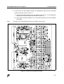
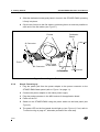
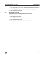
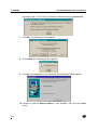
1
ST62GP-EMU2 HDS2 Series Emulator User Manual Release 1.2 December 2000 Ref: DOC-ST62GP-EMU2 USE IN LIFE SUPPORT DEVICES OR SYSTEMS MUST BE EXPRESSLY AUTHORIZED. STMicroelectronics PRODUCTS ARE NOT AUTHORIZED FOR USE AS CRITICAL COMPONENTS IN LIFE SUPPORT DEVICES OR SYSTEMS WITHOUT THE EXPRESS WRITTEN APPROVAL OF STMicroelectronics. As used herein: 1. Life support devices or systems are those which (a) are intended for surgical implant into the body, or (b) support or sustain life, and whose failure to perform, when properly used in accordance with instructions for use provided with the product, can be reasonably expected to result in significant injury to the user. 2. A critical component is any component of a life support device or system whose failure to perform can reasonably be expected to cause the failure of the life support device or system, or to affect its safety or effectiveness. Table of Contents Chapter 1: 1.1 1.2 Chapter 2: 2.1 2.2 2.3 2.4 Chapter 3: 3.1 3.2 3.3 Chapter 4: 4.1 4.2 4.3 4.4 4.5 4.6 4.7 4.8 Chapter 5: 5.1 5.2 5.3 5.4 5.5 5.6 5.7 5.8 5.9 5.10 5.11 Introduction . . . . . . . . . . . . . . . . . . . . . . . . . . . . . . . . . . . . . . . . . . 5 About this manual.... ..................................................................................... 7 Getting assistance ........................................................................................ 7 Getting Started . . . . . . . . . . . . . . . . . . . . . . . . . . . . . . . . . . . . . . . . 9 Delivery checklist .......................................................................................... 9 Adapters for SSOP devices ........................................................................ 11 installing the hardware ................................................................................ 11 How to power on and off ............................................................................. 17 WGDB6 . . . . . . . . . . . . . . . . . . . . . . . . . . . . . . . . . . . . . . . . . . . . . 19 Your system requirements .......................................................................... 19 Installing WGDB6 and other ST6 software tools ........................................ 19 Launching WGDB6 ..................................................................................... 21 Tutorial . . . . . . . . . . . . . . . . . . . . . . . . . . . . . . . . . . . . . . . . . . . . . 23 Introduction ................................................................................................. 23 Required tools ............................................................................................. 23 Getting prepared ......................................................................................... 23 Let’s go! ...................................................................................................... 24 Step Mode .................................................................................................. 27 Run Mode ................................................................................................... 34 Conclusion .................................................................................................. 35 Using the tutorial with ST62 devices other than the ST6265 ...................... 37 Emulator Features . . . . . . . . . . . . . . . . . . . . . . . . . . . . . . . . . . . . 39 Clock source ............................................................................................... 39 Dedication board oscillator ......................................................................... 39 Probe board oscillator ................................................................................. 39 External signal input on OSCIN pin ............................................................ 40 Changing the oscillator on the probe board ................................................ 40 Emulator electrical characteristics .............................................................. 42 Status LEDs ................................................................................................ 42 Step mode advantages of the ST62GP-EMU2 ........................................... 42 Using the trigger outputs ............................................................................. 43 Using the analyzer probe ............................................................................ 44 Emulator functional limitations and discrepancies ...................................... 45 3/57 1 Table of Contents Appendix A: Troubleshooting . . . . . . . . . . . . . . . . . . . . . . . . . . . . . . . . . . . . . . 47 A.1 A.2 Identifying the Problem ............................................................................... 47 Changing the Parallel Port Setup on Your PC ............................................ 48 Appendix B: Glossary . . . . . . . . . . . . . . . . . . . . . . . . . . . . . . . . . . . . . . . . . . . . 49 Product Support . . . . . . . . . . . . . . . . . . . . . . . . . . . . . . . . . . . . . . . . . . . . . . . . . 53 Getting prepared before you call............................................................................... 53 Contact List ............................................................................................................... 53 Software updates ...................................................................................................... 54 Index . . . . . . . . . . . . . . . . . . . . . . . . . . . . . . . . . . . . . . . . . . . . . . . . . . . . . . . . . . . 55 4/57 ST62GP-EMU2 Emulator User Manual 1 1 - Introduction INTRODUCTION Thanks for choosing ST6! This manual will help you get started with the ST62GPEMU2 emulator kit. The ST62GP-EMU2 Emulator Kit allows you to control the execution of programs that you have written for the ST62 series of MCUs and assists you in debugging your application hardware as well as your software. The real-time capability of the ST62GP-EMU2 allows you to run your application at full speed while still under debugger control. This allows you to test your program while running under the same conditions as the final application. Note: If you come across any terms or abbreviations you do not understand, you can check their meaning in the Glossary on page 49. First off, check that the ST6 MCU that you have picked for your application is in the list of devices supported by this emulator. You will be able to choose and emulate any of these 21 devices by configuring the ST6 debugger, WGDB6: Supported Devices Collectively known in this document as.... ST6200C ST620x ST6201C ST6203C ST6208C ST6209C ST6210C ST621x ST6215C ST6220C ST622x ST6225C ST6218C ST6218/28 ST6228C ST6252C ST625x ST6353C ST6255C 5/57 1 - Introduction ST62GP-EMU2 Emulator User Manual Supported Devices Collectively known in this document as.... ST6230 ST623X ST6232 ST6235 ST6260C ST626x ST6262C ST6263C ST6265C The ST6 HDS2 Emulator Series is a modular system. The emulator is principally made up of two boards: • The dedication board or DBE. • The main board. If you look at the emulator front panel, you will see that the main board is installed in the lower slot of the enclosure while the dedication board is installed in the upper slot. The main board is common to all ST6 HDS2 Emulators. It emulates the ST6 Program Memory and contains the breakpoint logic, trace memory and all the logic needed for real time emulation. The dedication board applies to the set of specific devices listed in the table above. It emulates all peripherals related to these devices (RAM, EEPROM, ADC, Timers, I/Os, etc.). With this modular architecture, once you have bought a complete emulator, you only need to change the dedication board (which is supplied with the probe boards included) to emulate other ST6 devices. In addition to the ST WGDB6 debugger, a third-party debugger, Raisonance’s WRKit Devopment Suite software package, is supported by the ST62GP emulator. This software is included in the MCU-on-CD CD-ROM provided with your emulator kit. 6/57 ST62GP-EMU2 Emulator User Manual 1.1 1 - Introduction About this manual.... Detailed instructions on how to install your emulator configuration are described in Chapter 2: Getting Started on page 9. How to install your software is described in Chapter 3: Installing the Software on page 19. Chapter 4: Tutorial on page 23 familiarizes you with the emulator environment using an example program. The emulator kit’s hardware features are described in Chapter 5: Features on page 39. 1.2 Emulator Getting assistance For more information, application notes, FAQs and software updates on all the ST microcontroller families, check out the CD-ROM or our website: http://mcu.st.com For assistance on all ST microcontroller subjects, or if you need help with using your emulator, refer to Product Support on page 53. We’ll be glad to help you! 7/57 1 - Introduction 8/57 ST62GP-EMU2 Emulator User Manual ST62GP-EMU2 Emulator User Manual 2 GETTING STARTED 2.1 Delivery checklist 2 - Getting Started The following items are packed with the ST62GP-EMU2 (refer to Figure 1 ): • ST62GP-EMU2 box with two flat cables for connecting a probe. • One DB324/DIP probe board for use with ST6230, ST6218 and ST6228 target devices. • One DB324/SDIP42 probe board for use with the ST6232 target device. • One DB448 probe board for use with ST620x, ST621x and ST622x target devices. • One DB449 probe board for use with 5x and 6x devices, including: - 16-pin probe with 3 different male-male interfaces, depending on the target device. - 20-pin probe with 3 different male-male interfaces, depending on the target device. - 28-pin probe with 3 different male-male interfaces, depending on the target device. A duplicate set of these interfaces is provided in case of damage. Caution: Note: Take precautions against electrostatic discharge (ESD) before unpacking the emulator probe boards. These boards must only be handled in a static-safe area. • Three probe adapters—DIP16, DIP20 and DIP28—to be soldered to a footprint. • Three SO adapters—SO16, SO20 and SO28. If the probe boards are already assembled with SO adapters, refer to Figure 3 on page 12 for how to use the DIP connectors, if required. • One parallel interface cable (Ref.: DB25M/DB25M). • One power adapter. • One power cable. • Two ferrites to be clipped over the flat cables (for EMC compliance). • Analyser probes. • A CD-ROM, containing the WGDB6 debugger software. (Not shown). • This manual. (Not shown). 9/57 2 - Getting Started Note: ST62GP-EMU2 Emulator User Manual Do not use other parallel interface cables, power adapters or other accessories with the ST62GP-EMU2. Flat Cables ST62GP-EMU2 Box Power Adapter Power Cable Parallel Interface Cable 4 Probe Boards: DB324/DIP DB324/SDIP DB448 DB449 Analyzer Probes Ferrites DB324 Interface Adapters SO Adapters DIP16 DIP20 DIP28 SO16 SO20 SO28 Figure 1: ST62GP-EMU2 Emulator Kit Contents 10/57 ST62GP-EMU2 Emulator User Manual 2.2 2 - Getting Started Adapters for SSOP devices If you wish to emulate SSOP devices, you must order the following adapters: • 16-pin SSOP adapter (Ref.: DB381). • 28-pin SSOP adapter (Ref.: DB388). Refer to Product Support on page 53 for a contact list of qualified STMicroelectronics representatives near you. 2.3 installing the hardware To set up your emulator hardware, follow these steps: 2.3.1 Step 1: Connecting the emulator to your PC 1 Shut down and power off the PC that is to be connected to the ST62GP-EMU2. 2 Ensure that both the ST62GP-EMU2 emulator and your application board are disconnected from their power supplies. 3 Connect the parallel interface cable supplied with the ST62GP-EMU2 emulator kit to a parallel connector on your PC (LPT1 or LPT2). 4 Connect the parallel interface cable to the parallel port connector on the back panel of the ST62GP-EMU2 (See Figure 2 ). Parallel Port Power Connector Power ON/OFF Switch Figure 2: ST62GP-EMU2 Back Panel 2.3.2 Step 2: Putting together your emulator probe 1 Select one of the emulator probes supplied in the package and mount the footprint adapter for SO devices if necessary (refer to Figure 3 ). Table 1 11/57 2 - Getting Started ST62GP-EMU2 Emulator User Manual indicates which probe board and footprint should be used with your target device. Fixed DIP Connector SO Adapter Replaceable DIP Connector (keep in place to protect fixed DIP connector from pin breakage) Figure 3: DIP Probe Connectors with SO Adapter Target device Probe Board ST6200C ST6201C DB448 with DIP16 footprint: interface to be added ST6203C ST6208C ST6209C ST6210C DB448 with DIP20 footprint: interface to be added ST6220C ST6215C ST6225C ST6252C ST6262C DB448 with DIP28 footprint: interface to be added DB449 with DIP16 footprint: interface to be added Table 1: Use of Probe Boards and Footprints 12/57 ST62GP-EMU2 Emulator User Manual Target device 2 - Getting Started Probe Board ST6353C ST6260C DB449 with DIP20 footprint: interface to be added ST6263C ST6255C DB449 with DIP28 footprint: interface to be added ST6265C ST6230C DB324 with DIP28 footprint: interface to be added ST6232C DB324 with SDIP42 footprint ST6235C DB324 with QFP52 footprint: third probe must be ordered separately ST6218 DB324 with DIP20 footprint: interface to be added ST6228 DB324 with DIP28 footprint: interface must be added Table 1: Use of Probe Boards and Footprints 2 Configure the probe board settings using the information in Table 2. Jumper W1 W2 Setting Function Remark 1-2 Clock source is user-installed oscillator on probe board in the OSCILLA position. Refer to Clock source on page 39 for more information. 2-3 Clock source is a signal input on the probe board in the OSCIN position. 1-2 Jumper installed: Disable userinstalled oscillator on probe board No jumper: Enable user-installed oscillator on probe board. This jumper must be installed if an oscillator on the probe board is not used. Table 2: Probe Settings 13/57 2 - Getting Started 2.3.3 ST62GP-EMU2 Emulator User Manual Step 3: Connecting the emulator to the probe 1 Remove the dedication board from the ST62GP-EMU2 enclosure as follows: a Completely loosen the two screws on the front panel of the dedication board (see Figure 4 ). Flat Cable Exit Left Extractor Handle Right Extractor Handle Screw Screw Dedication board Main Board Wait Run Stop Power ST6 HDS2 Emulator Triggers Analyzer Probe Figure 4: ST62GP-EMU2 Front Panel b Extract the board by placing your thumbs on the two handles and pressing them firmly outwards to loosen the board (see Figure 5). c Slide the board out gently and place it on a static-safe surface. Dedication Board Main Board Figure 5: Using the extractor handles to loosen the dedication board 14/57 ST62GP-EMU2 Emulator User Manual 2 2 - Getting Started Connect the two flat cables between the dedication board and the emulator probe as follows (refer to Figure 7): a Connect one flat cable to J1 on the probe board and J1 on the dedication board (see schema of dedication board in Figure 6). b Connect the other flat cable to J2 on the probe board and J2 on the dedication board. Note: The cable must be kept parallel between the emulator and the probe. J2 J1 Figure 6: Schema of Dedication Board 15/57 2 - Getting Started ST62GP-EMU2 Emulator User Manual 3 Slide the dedication board gently back in its slot in the ST62GP-EMU2, pressing it firmly into place. 4 Clip the two ferrites to the flat cables, positioning them as close as possible to each end of the flat cables (see Figure 7 ). Dedication Board Ferrites J2 Connector Probe PIN 1 edges J1 Connector of flat cables J1 Connector J2 Connector Figure 7: Installing the Flat Cables 2.3.4 16/57 Step 4: Powering up 1 Plug the power jack from the power adapter to the power connector on the ST62GP-EMU2 back panel (refer to Figure 2 on page 11). 2 Connect the power adapter to the mains power supply. 3 Plug the probe connector in the MCU socket of the application board. 4 Power on the PC. 5 Switch on the ST62GP-EMU2 using the power switch on the back panel (see Figure 2). 6 The power LED on the front panel should light up (see Figure 4). If not, refer to Troubleshooting on page 47, otherwise proceed to the next step. ST62GP-EMU2 Emulator User Manual 2.4 2 - Getting Started 7 To run the emulator, you must now install the Windows Debugger Software for ST6 (WGDB6). To do this, refer to Installing the Software on page 19. 8 Power on the application board. How to power on and off When powering on the emulator, always proceed in this order: 1 Power on the development PC. 2 Power on the ST62GP-EMU2. 3 Start WGDB6 and load your program. 4 Power on the application board. When turning off the emulator, proceed in the reverse order. 17/57 2 - Getting Started 18/57 ST62GP-EMU2 Emulator User Manual ST62GP-EMU2 Emulator User Manual 3 WGDB6 3.1 Your system requirements 3 - WGDB6 To run/install the software provided on the MCU on CD CD-ROM, you must have a PC running either Microsoft® Windows® 95, Windows® 98 or Windows® NT®. 3.2 Installing WGDB6 and other ST6 software tools Your emulator comes with the MCU on CD CD-ROM which contains a number of ST6 software tools. To install them, follow these steps: 1 Place the MCU on CD CD-ROM in your CD-ROM drive. The CD-ROM’s autorun feature opens up a welcome screen on your PC. If the autorun feature does not work, use Windows® Explorer to browse to the CD-ROM’s root folder, and double-click on welcome.exe. 2 Select Install Your Development Tools from the list of options. A new screen appears listing the different families of STMicroelectronics MCUs. 3 Use your mouse to place the cursor over the ST6 TOOLS option. Choose ST TOOLS and ST6 TOOLCHAIN from the lists that appear. 4 The install wizard is launched. Follow the instructions that appear on the screen. You can choose the package you wish to install. To install the complete ST6 Toolchain for your emulator, select Complete Toolchain for Emulator. This option installs the WGDB6 debugger version for your emulator, as well as a Windows Epromer and ST6 Assembler-Linker software. Alternatively, you can choose to perform a custom installation where you choose which of the available software applications you wish to install. Note: In order to configure your emulator, you must, as a minimum, install the ST6 WGDB6 for Emulator If you do not choose any options, but click Next>, the ST6 Assembler-Linker will be installed by default. 5 Follow the instructions that appear on your screen. You will be prompted to select the parallel port you wish to connect the emulator to, as well as the program folder that the software will be installed to. 6 If you are installing WGDB6 on a Windows ® NT® platform, you must install the Windows® NT® parallel port driver supplied on the CD-ROM. 19/57 3 - WGDB6 ST62GP-EMU2 Emulator User Manual A window pops up if you have not already installed this driver (parstm.sys ). 7 Click OK. The following window appears: 8 Click Install. The following window appears: 9 Click OK, the installation is now complete. The following window appears. 10 Choose to read the Release Notes or start WGDB6, then click the Finish button. 20/57 ST62GP-EMU2 Emulator User Manual 3.3 3 - WGDB6 Launching WGDB6 From Windows® 95, 98 or Windows® NT, click the Start button, point to Programs -> ST6 Tool Chain -> Development Tools, then choose Wgdb6 Emulator. Refer to the WGDB6 Windows Debugger for the ST6 Family User Manual for full instructions on how to use WGDB6. This manual is available in PDF format on the MCU on CD CD-ROM. 21/57 3 - WGDB6 22/57 ST62GP-EMU2 Emulator User Manual ST62GP-EMU2 Emulator User Manual 4 TUTORIAL 4.1 Introduction 4 - Tutorial The goal of this tutorial is make you familiar with the emulator environment using an example program installed in the following directory: D:\Program Files\Stm\ST6toolchain\soft The example uses the standard timer of the ST6265 to toggle an I/O pin (PB0). You can easily modify this example to work with other devices, because the hardware resources it uses can be found on all ST6 devices supported by the ST62GP-EMU2. To find out how to modify the program, refer to Using the tutorial with ST62 devices other than the ST6265 on page 37. The example program is located in the following directory: D:\Program Files\Stm\ST6toolchain\soft\6x-emu2\tutorial The file is called tutorial.asm. 4.2 Required tools The following tools are required to do this tutorial: 4.3 • ST62GP-EMU2. • Oscilloscope. • 5 V power supply. Getting prepared Before you start the tutorial, make sure your system has been correctly set-up. To do so: 1 2 Install the ST62GP-EMU2 emulator as described in installing the hardware on page 11. - The tutorial example is based on a ST6265 device. - On the 28-pin DB449 probe board, there should be a jumper in W2 (jumper W1 is irrelevant in this case). Install the software (i.e. the WGDB6 debugger) as described in Installing the Software on page 19. 23/57 4 - Tutorial 4.4 ST62GP-EMU2 Emulator User Manual Let’s go! This section gives you a quick step-by-step procedure, showing how to Run & Step through the tutorial.asm tutorial program. Note: Refer to the comments in the tutorial.asm program for information on what each instruction does. In this example, since we are not using an application board, you should connect the probe to a regulated 5 V power supply Caution: • VDD (pin 11): 5 V • VSS (pin 12): 0 V Be careful when applying the 5 V to ensure that you don’t short circuit the emulator. 1 Start the WGDB6 Emulator: 2 From the Windows Start menu, select Start -> Programs -> ST6 Tool Chain > Development Tools -> Wgdb6 -> Emulator ST6. This starts the software used for emulation. The About WGDB6 window (see Figure 8) pops up. Note: Do not click the “OK” button but wait for the communications link between the emulator and the PC to be synchronized. Figure 8: About WGDB6 window 24/57 ST62GP-EMU2 Emulator User Manual 3 4 - Tutorial After synchronization is completed, the Control Bar window (see Figure 9 ) pops up. Figure 9: Control Bar window 4 Once the WGDB6 is launched you can select a DBE family by selecting Commands-> DBE Family -> ST6xxx from the main menu. 5 After selecting the DBE family, select Commands -> Micro_Name..., the Micro Name window is displayed (see Figure 10). Figure 10: Micro Name window 6 In the Micro Name window choose a family from the pull down list and then choose a micro from the micro list. 7 After you have selected the correct emulator, from the main menu, select Commands -> Micro_Configuration.... Depending on the emulator selected, different configuration options are available. 25/57 4 - Tutorial ST62GP-EMU2 Emulator User Manual For example, the ST6265 emulator has the following Micro Configuration options: However, the ST6200 emulator has the following Micro Configuration options: 26/57 ST62GP-EMU2 Emulator User Manual 4 - Tutorial The first option, frequency, is the same for all emulators. The options listed below this depend on the specific emulator. 8 Open the tutorial.hex file by selecting File -> Open from the main menu, and then browsing to D:\Program Files\Stm\ST6toolchain\soft\6xemu2\tutorial where the tutorial.hex file is located. Double-click on the file to open it. 9 A window titled tutorial.asm (see Figure 11) pops up and the title of the Control Bar changes to ST626x Emulator tutorial.hex. Figure 11: tutorial.asm window There are two ways of executing the tutorial.hex file, one way is to Step through each of its instructions and the other is to Run through each of its instructions. Both will be described in this tutorial, beginning with stepping. 4.5 Step Mode In this procedure, we learn how to execute programs step-by-step. Before doing this, we must setup the Watch window, to observe what happens when each instruction is executed. 27/57 4 - Tutorial ST62GP-EMU2 Emulator User Manual 1 In the Control Bar, click Windows -> Browser. The Browser window pops up (see Figure 12). Figure 12: Browser window 2 28/57 In the Browser window, click the arrow next to Type, select data and click Apply. ST62GP-EMU2 Emulator User Manual 3 4 - Tutorial Scroll through the symbols to find DDRB, click it once to highlight it and then click Add To Watch. This causes the Watch window (see Figure 13) which displays the contents of DDRB to pop up. Figure 13: Watch window Note: Note: 4 In the Watch window, click on DDRB and then Display, Base, Hexadecimal. This changes the DDRB register (because it is highlighted) from decimal to hexadecimal notation. Then click Display, Prefs and Hexa - this will make any new register that is added to the Watch window be displayed in hexadecimal format. 5 Make the Watch window smaller and move the Watch, Browser, tutorial.asm and Control Bar windows to a location on the screen where they can all be easily read. 6 In the Browser window, add the following registers to the Watch window in the same way that you added DDRB: ORB, DRB, drbcopy, IOR, TSCR and TCR. Close the Browser window. You can also type the names of the registers directly in the Watch window. 7 In the Control Bar, click Commands, then Reset. This resets the microcontroller and places the Program Counter at the Reset vector. 8 In the Control Bar, click Step. This executes only one instruction and since the instruction at the Reset vector is jp reset, it will jump to where the label reset is located. After the jp reset instruction is executed, the ldi DDRB,01h instruction will be highlighted. The highlighted instruction is the next one to be executed. Results: The Watch window shows the DRB value to be FFh in hexadecimal as shown in Figure 14 . This is due to the Port B configuration: all the Port B I/ 29/57 4 - Tutorial ST62GP-EMU2 Emulator User Manual Os are defined as input with pull-up (reset state). The pull-ups have the effect that the pins are all high (logic 1), and because they are all configured as input this means their logic state is read from the DRB. The other variables (drbcopy...) are not yet initialized at this stage. Figure 14: tutorial.asm and Watch windows 9 Note that in the Watch window, the contents of the DDRB register is 00h in hexadecimal notation. In the Control Bar click the Step button again. This loads the hexadecimal value 01h into the DDRB register. 10 Click the Step button again. This loads the hexadecimal value 01h into the ORB register. 11 Click the Step button again. This loads the hexadecimal value 00h into the drbcopy register. 30/57 ST62GP-EMU2 Emulator User Manual 4 - Tutorial We could continue this Stepping process and watch each register being loaded, as the instructions are executed one-by-one, but for the purposes of this tutorial we will leave the Stepping process and continue executing the program without stepping. 12 In the tutorial.asm window, scroll down to the jrs 0,drbcopy,lowbit instruction and click it once - this highlights the instruction in blue. This instruction is in the Timer Interrupt Service Routine and will not be reached until the timer interrupts the program (which means that it counts down to zero). 13 Click the Break button - this causes the instruction to be displayed in bold (see Figure 15) which means a breakpoint has been set at this instruction. Figure 15: tutorial.asm window showing set breakpoin 31/57 4 - Tutorial ST62GP-EMU2 Emulator User Manual 14 In the Control Bar, click the Cont button - this runs the program from the current Program Counter location without stopping until a breakpoint is encountered (see Figure 16). Figure 16: Breakpoint encountered 15 After the program stops running (note that it has stopped where the breakpoint was set), click the Step button in the Control Bar. It executes the jrs 0,drbcopy,lowbit instruction which tests the zero bit of the drbcopy register to see if it is a “1” or a “0”. If it is a “1”, then it jumps to the label referred to as lowbit. In our case the zero bit is “0”, so the jrs instruction does not make a jump and the next instruction is highlighted (ldi drbcopy,01h). 16 Click the Step button again - this loads the hexadecimal value 01h into the drbcopy register. Results: Look at the oscilloscope which is displaying the voltage level of pin PB0 and note that it is low (0 V). 17 Click the Step button again - this loads the hexadecimal value 01h into the DRB register. Results: Look at the oscilloscope which is displaying the voltage level of pin PB0 and note that it has changed to high (5 V). The reason why it changed is because the last instruction that was executed changed PB0 from Output 32/57 ST62GP-EMU2 Emulator User Manual 4 - Tutorial Push-Pull with a “0” in its data register to Output Push-Pull with a “1” in its data register. Note: In the Watch window, the contents of the TSCR register is EFh in hexadecimal notation. 18 In the Control Bar click the Step button. This resets the 7th bit of the TSCR register, making its value change to 6Fh. 19 In the Control Bar click the Cont button. This runs the rest of the instructions and does not stop until a breakpoint is encountered. The Cont button runs the code from the current Program Counter location (the last instruction that was executed). 20 After the program stops running (note that it stops at the same breakpoint that was set before) click the Step button in the Control Bar. It executes the jrs 0,drbcopy,lowbit instruction which tests the zero bit of the drbcopy register to see if it is a “1” or a “0”. If it is a “1” then it will jump to the label referred to as lowbit, otherwise it will not jump and the next instruction will be executed, but since the zero bit of the drbcopy register is a “1” it will jump to the lowbit label. 21 Click the Step button again, this loads the hexadecimal value 00h into the drbcopy register. Results: Look at the oscilloscope which is displaying the voltage level of pin PB0 and note that it is high (5 V). The voltage level of PB0 is 5 V because PB0 is configured as Output Push-Pull with a “1” in its data register (DRB). 22 Click the Step button again - this loads the hexadecimal value 00h into the DRB register. Results: Look at the oscilloscope which is displaying the voltage level of pin PB0 and note that it has changed to low (0 V). The reason why it changed is because the last instruction that was executed changed PB0 from Output Push-Pull with a “1” in its data register to Output Push-Pull with a “0” in its data register. Note: In the Watch window that the contents of the TSCR register is EF in hexadecimal notation. 23 In the Control Bar click the Step button. This resets the 7th bit of the TSCR register, making its value change to 6Fh. If we carry on clicking the Cont button and stepping through the code we can see that PB0 changes from a logic “0” (low - 0 V) to a logic “1” (high - 5 V) and vice-versa. But, instead of doing that we will stop “Stepping” through the code and “Run” through it instead. 33/57 4 - Tutorial 4.6 Note: 34/57 ST62GP-EMU2 Emulator User Manual Run Mode 1 In the tutorial.asm window, scroll up to the jrs 0,drbcopy,lowbit instruction and click it once. This highlights the instruction in blue. This instruction is in the Timer Interrupt Service Routine. Click the Break button - this turns the instruction back into normal lettering as opposed to bold lettering which means the breakpoint has been removed from this instruction. 2 In the Control Bar click the Run button and watch the oscilloscope which is displaying the voltage level of pin PB0. You will see it change from low to high and high to low continuously. This is a 10.17 Hz PWM signal with 50% Duty Cycle. You may have to adjust the oscilloscope to the right setting to see the 10.17 Hz PWM signal. This PWM will not stop until you click the Stop button in the Control Bar. The Run button runs the code from the reset vector whereas the Cont button runs the code from the current Program Counter location (the last instruction that was executed). ST62GP-EMU2 Emulator User Manual 4.7 4 - Tutorial Conclusion Now that you have finished this tutorial, you can start stepping and running your own code in exactly the same way as we have done with the tutorial.asm program. You can customize your debug session by launching other windows from the Windows menu on the Control Bar such as: • The Stack window for displaying the stack status. • The Register window for inspecting the core registers (accumulator, index registers etc.). • The Dump window for inspecting any location in your memory (data and program space). • The Trace window for a log of all the instructions executed. These windows are shown in Figure 17 . You can find the files for this advanced debug session in : D:\Program Files\Stm\ST6toolchain\soft\6xemu2\tutorial\wsd_file. 35/57 4 - Tutorial ST62GP-EMU2 Emulator User Manual If you have any questions please contact your local STMicroelectronics Microcontroller support person (refer to Product Support on page 53). Figure 17: Stack, Registers and Dump windows 36/57 ST62GP-EMU2 Emulator User Manual 4.8 4 - Tutorial Using the tutorial with ST62 devices other than the ST6265 You can easily modify the tutorial program to target a device other than the ST6265. You need only take into account the interrupt channel to which the timer is connected. Any other I/O port can be used for outputting signals. To do so, proceed as follows: 1 In the tutorial.asm file find the following line of code and modify the device version to reflect the new target device: .vers “ST6265” 2 In the tutorial.asm file find the following line of code and modify the romsize parameter as appropriate: .romsize 4 3 ; Optional ; Optional Change the hardware register definition file (*.INI) to that associated with the device you want to target. These files can be found in the following directory: D:\Program Files\Stm\ST6toolchain\soft\6x-emu2\inc_file. 4 If necessary, refer to the device datasheet in order to remap the microcontroller device vector. 5 Refer to the device data sheet in order to check the ST6 memory mapping, modify the tutorial.asm file as appropriate (.org and block instructions). 6 Select the appropriate device name in the debugger. 37/57 4 - Tutorial 38/57 ST62GP-EMU2 Emulator User Manual ST62GP-EMU2 Emulator User Manual 5 EMULATOR FEATURES 5.1 Clock source 5 - Emulator Features The clock source can be configured by software on the dedication board and using jumpers W1 and W2 on the probe board. The clock source can also be configured from an oscillator on the: • Probe board, or • TTL signal input to the OSCIN pin of the probe. Note: A crystal or ceramic resonator on the application board must not be used as a clock source for the emulator. 5.2 Dedication board oscillator The dedication board oscillator is selectable with the software. Possible selections are: 5.3 • 500kHz • 1MHz • 2MHz • 3MHz • 4MHz • 5MHz • 6MHz • 7MHz • 8MHz Probe board oscillator The probe board has locations for soldering a crystal or a ceramic resonator which can be used as the clock source of the emulated MCU. To select this, Note: 1 Select EXTERNAL in the menu Command -> Micro_Configuration -> Frequency. 2 Remove the jumper between pins 1-2 of W2 on the probe board. 3 Install a jumper between pins 1-2 of W1 on the probe board. When you install an oscillator on the probe board, you may have to change the capacitors (refer to Changing the oscillator on the probe board on page 40). 39/57 5 - Emulator Features 5.4 ST62GP-EMU2 Emulator User Manual External signal input on OSCIN pin To select this, 5.5 1 Select EXTERNAL in the menu Command -> Micro_Configuration -> Frequency. 2 Install a jumper between pins 2-3 of W1 and pins 1-2 of W2 on the probe board. Changing the oscillator on the probe board If you install a crystal or a ceramic resonator on the probe board, you must change the value of the C4 and C5 capacitors (C3 and C4 capacitors in the case of a DB324 probe board) accordingly (see Figure 18). The capacitors installed (470 pF, 1000 pF) have been tested with crystals in the range 1 to 4 MHz; however, the results you obtain will depend on the characteristics of the crystal you use. These two capacitors can be modified. M74HC04 (drives userinstallable oscillator) Figure 18: Probe board layout 40/57 GND 1 3 5 7 9 11 13 15 17 19 21 23 25 27 29 31 33 35 37 39 41 43 45 47 49 HE10-50DM 2 4 6 8 10 12 14 16 18 20 22 24 26 28 30 32 34 36 38 40 42 44 46 48 50 J2 PE0 PE1 PE2 PE3 PE4 PE5 PE6 PE7 PA0 PA1 PA2 PA3 PA4 PA5 PA6 PA7 PC1/TIM1/ADC NMIAPP AVSS AVDD PD0 PD1 PD2 PC1 GND C4 470PF VSREF TIMER VCC TP5 2 Analog references used only by ST623X families GND TP3 TP2 resonator GND XT1 10M R3 74HC04 8MHZ-XT-P 1 U4A GND C5 10NF R4 3.3 3 4 VCC NRES PB7 PB6 2 1 2 3 EXTAL MW3X1C 1 2 3 W1 GND 100NF C2 5 GND VCC 6 R2 100K R1 100K 74HC04 U4C 1 2 3 4 5 6 7 8 9 10 11 12 13 14 28 27 26 25 24 23 22 21 20 19 18 17 16 15 DIP28 1 2 3 4 5 6 7 8 9 10 11 12 13 14 U3 28 27 26 25 24 23 22 21 20 19 18 17 16 15 PA0 PA1 PA2 PA3 PA4 PA5 PA6 PA7 PB0 PB1 PB2 PB3 PB4 VSREF 20 19 18 17 16 15 14 13 12 11 DIP20 1 2 3 4 5 6 7 8 9 10 U1 20 19 18 17 16 15 14 13 12 11 PB0 PB1 PB2 PB3 PB4 PA0 PA1 PA2 PA3 VSREF 1 2 3 4 5 6 7 8 16 15 14 13 12 11 10 9 DIP16 1 2 3 4 5 6 7 8 U2 16 15 14 13 12 11 10 9 VSREF PA1 PA2/ADC PA3/ADC PB0 PB1 PB3 PB5 16 PIN PROBE CONNECTORS 1 2 3 4 5 6 7 8 9 10 20 PIN PROBE CONNECTORS VCCAPP OSCIN OSCOUT NMIAPP NRES PB7 PB6 PB5 W2 MW2X1C 28 PIN PROBE CONNECTORS VCCAPP PC1 OSCIN OSCOUT NMIAPP PB7 PB6 PB5 NRES PC7 PC6 PC5 PC4 VCCAPP TIMER OSCIN OSCOUT NMIAPP OSCIN 74HC04 U4B 1 PA2 PA3 9 8 GND 74HC04 U4D 10 R5 GND XTAL OSCOUT 100PF 10 C5 R6 VCC TEST NRES VDD VDDP PC7 PC6 PC5 PC4 + VSS VSSP PB7 PB6 PB5 PB4 PB3 PB2 PB1 PB0 PD7 PD6 PD5 PD4 PD3 TP8 HE10-50DM 2 4 6 8 10 12 14 16 18 20 22 24 26 28 30 32 34 36 38 40 42 44 46 48 50 1 3 5 7 9 11 13 15 17 19 21 23 25 27 29 31 33 35 37 39 41 43 45 47 49 VCC_EMU J1 GND TP4 (Not connected) NRESETAP PC3 PC2 PC0 XTAL EXTAL TP1 C10 C11 10MF-CT-16V 100NF VCC VCC_EMU GND ST62GP-EMU2 Emulator User Manual 5 - Emulator Features You can find these components in the following schematic: 41/57 5 - Emulator Features ST62GP-EMU2 Emulator User Manual 5.6 Emulator electrical characteristics 5.6.1 Voltage measurement on VDD/VSS probe pins when disconnected from application board If you measure the voltage on the power pins of the probe when disconnected from the target application, it will be much lower than the operating voltage of 5 V. This is normal, because the VDD pin of the probe is used as a reference voltage by the emulator. It aligns itself to the application voltage level when the probe is plugged into the application board and the application board is powered-on. 5.6.2 Power consumption of probe The M74HC04 on the probe board (see Figure 18 on page 40 for its position) is intended for driving a user-installable oscillator. This M74HC04 is always under power. To obtain 0 A power consumption on the probe board, remove the M74HC04 if you do not need it to drive an oscillator. 5.7 Status LEDs Three LEDs on the front panel of the ST62GP-EMU2 show the user the state of the emulated ST62 device as follow: Stop On 5.8 Wait Run Meaning On ST62 device is in Run mode (core at full speed) On On ST62 device is in Wait mode On On ST62 device is in Stop mode Step mode advantages of the ST62GP-EMU2 The ST626P-EMU2 emulator, when run with the WGDB6 debugger in step mode, has the following characteristics: • A/D End of Conversion flag when debugging in step mode The A/D converter clock is always present and the A/D conversion is performed at full speed, even when stepping through the program. This will result in the EOC flag appearing to be set immediately when the conversion is started. • 42/57 SPI communication when debugging in step mode ST62GP-EMU2 Emulator User Manual 5 - Emulator Features The SPI data register operates at full speed even in Step mode. For example, if you load the Data register in Step mode, the value will be output immediately on the pin. 5.9 Using the trigger outputs Two connectors for trigger output signals are available on the front panel of the ST62GP-EMU2. You can generate these signals using the Hardware Events/Trigger Menu in the WGDB6 Debugger. Output OUT1 and OUT2 can be programmed in two ways: • Synchronization mode (see Figure 19) allows you to configure two synchronization pulses (Trig1 and Trig2) for triggering external hardware. The events can be defined by addresses or address ranges. Trigger Event: Trig1 OUT1 Trigger Event: Trig2 OUT2 Figure 19: Synchronization Mode • Timing measurement mode (see Figure 20) allows you to measure the time elapsed during a subroutine for example, using an oscilloscope connected to OUT1. In this case, output OUT2 is SET on a user-defined address (Trig1), and RESET on another one (Trig2). 43/57 5 - Emulator Features ST62GP-EMU2 Emulator User Manual OUT1 is the ST6 clock signal (fINT) gated by OUT2. fINT OUT1 Measurement End: Trig2 Measurement Start: Trig1 OUT2 Figure 20: Timing Measurement Mode 5.10 Using the analyzer probe The ST62GP-EMU2 has an input connector for up to 4 external signals which can be used to capture signals from your application hardware to be used as logical conditions for conditional breakpoints. GND +5V 5 4 6 2 3 7 8 1 9 Lp3 Lp2 Lp1 Lp0 Figure 21: Analyzer Probe Connector Pin Assignment By connecting the analyzer probe to various test points on your application board, you can set up breakpoints that will be triggered depending on the state of your application hardware, plus any other software conditions you may have configured for the breakpoint. 1 44/57 In the WGDB6 Main Window, click Hardware Events, then Memory Breakpoints. The Memory Breakpoints window opens. ST62GP-EMU2 Emulator User Manual 2 5 - Emulator Features Click the Conditions button. The Hardware Conditions window opens as shown in Figure 22 . Figure 22: Hardware conditions window 3 In the Logic probe box, click the Enable button beneath the logic probes whose values you want to consider. 4 While still in the Logic probe box, click the Value buttons to set the logic probe values on which you want to break. Click OK. These signals must be connected on the Lp (Logic Probe) pins of the Analyzer probe connector on the front panel of the ST62GP-EMU2. The inputs are CMOS compatible at 5 V. For more information on breakpoints, refer to the WGDB6 manual or to the WGDB6 on-line help. 5.11 Emulator functional limitations and discrepancies 5.11.1 ST6 device options On most ST6 devices, you can select device options which are described in the datasheet option list and option byte sections (refer to the ST6 Databook or CDROM). The ST62GP-EMU2’s functional limitations as regards device options are listed below. 45/57 5 - Emulator Features 5.11.2 ST62GP-EMU2 Emulator User Manual Oscillator Safeguard Enable (OSGEN) option When this option is selected the OSG and LFAO frequencies are fixed as follows: Note: VDD OSG LFAO 2.4 V to 3.6 V 2 Mhz 200 khz 3.6 V to 4.5 V 4 Mhz 400 khz 4.5 V to 6 V 8 Mhz 800 khz The OSG and LFAO frequencies of the ST62GP-EMU2 are fixed relative to VDD. However, on real devices the OSG and LFAO frequencies may vary depending on both VDD and the device temperature. 5.11.3 Optional external RC network (OSCIL) Not supported by the emulator. Note: The restrictions above should not prevent you from fully debugging your software, although you will not be able to test these features using the emulator. 5.11.4 Electrical characteristics of A/D converter input pins The emulator ADC input pins have an input capacitance AC IN of 120 pF on the emulator, compared to 5 pF on the ST6 device. This has the effect that, when you switch A/D channels using the emulator, the first conversion may be wrong. This conversion error will not occur when the ST6 target device is installed in the final application. 5.11.5 Other known problems 5.11.5.1 WAIT and STOP mode In the WGDB6 debugger, if an Inspect window is used in real time mode (i.e. red background color) while your program is in STOP or WAIT mode (assuming your program contains these instructions), this causes the emulator to exit these modes. This means that real-time use of the Inspect window causes the clock to be reactivated, and the normal running of your program may be disrupted (especially if the STOP or WAIT mode was to facilitate the collection of data). 46/57 ST62GP-EMU2 Emulator User Manual Appendix A: Troubleshooting APPENDIX A:TROUBLESHOOTING A.1 Identifying the Problem IF..... .... THEN 1 The power status LED on the ST62GP-EMU2 front panel is off. Check the power cable connections. Check the power switch on the ST62GP-EMU2 back panel. 2 The Run status LED does not switch on when you start your program. Check the title bar of the WGDB6 main window, you may be in WGDB6 Simulator instead of WGDB6 Emulator. 3 WGDB6 crashes. Remove the wgdb6win.ini from the C:\Windows directory and the filename.wsd file from the working directory. If this does not solve the problem, save any work files, delete the directory c:\Program Files\Stm\St6toolchain\soft and re-install WGDB6. 4 Error message: -hds2 -lpt1 timeout during synchronization 5 Error message: Check if the emulator is switched on and if the parallel cable is well connected. 6 Error message: No message received from the emulator. 7 Error message: Check that the ST62GP-EMU2 is connected to LPT1 and check if the power supply is on. This message is also displayed when there is a configuration mismatch. Configure the parallel port of your PC, referring to Changing the Parallel Port Setup on Your PC on page 48. If the problem persists, save any work files, delete the directory c:\Program Files\Stm\St6toolchain\soft and re-install WGDB6. Check that the ST62GP-EMU2 is powered on, and that the emulator boards are fully inserted in their slots. Close WGDB6 and restart Windows. This action is forbidden while the emulator is running. 8 Error message: Error FS_TargetReadonly. This message can occur if WGDB6 is installed over an existing version. To correct this problem, save any work files, then delete the directory c:\Program Files\Stm\St6toolchain\soft before reinstalling WGDB6. 47/57 Appendix A: Troubleshooting A.2 ST62GP-EMU2 Emulator User Manual Changing the Parallel Port Setup on Your PC If you see this message displayed while you are installing WGDB6, “Check if the emulator is switched on and if the parallel cable is well connected.” this may mean that the setup of the LPT1 or LPT2 port on your PC is not compatible with the ST62GP-EMU2. This is a problem with some Windows 95/98 PCs but usually not with Windows NT PCs. To setup the port correctly: 48/57 1 Shutdown and restart your PC in order to enter the BIOS Setup. 2 Follow the messages displayed on the screen and when prompted, press the key required to enter the BIOS Setup (usually a Function key or ESC key). 3 Select the parallel port settings menu. 4 Change the mode of the LPT port used for the Emulator to ECP, EPP, Bidirectional or Centronics mode (not SPP, Standard, Unidirectional or Printer Mode). 5 Save your changes and exit the setup. ST62GP-EMU2 Emulator User Manual Appendix B: Glossary APPENDIX B:GLOSSARY ADC Analog-to-digital converter. Dedication board A dedication board is one of the two boards installed in the enclosure of the ST62GP-EMU2. It is the part of the emulator that is specific to a set of ST6 devices. It emulates the RAM, EEPROM, oscillator, timers, watchdog, ADC, SPI and I/Os. It is connected to the probe board by two flat cables. The ST6 HDS2 emulator is available in specific versions that support a group of ST6 devices. Each version of the ST6 HDS2 has a specific dedication board and set of probe boards. DIL or DIP Dual In Line, also known as Dual In Line Package. These two abbreviations designate a type of device package with two rows of pins for thru-hole mounting. ECP Extended capabilities port. EPP Enhanced parallel port. Footprint Designates the dimensions of the location of a component on a printed circuit board or in a socket. It depends on the number of pins, their size, type and positioning. The footprint of each ST6 device is specified in the datasheet in the section titled Package Mechanical Data. (see the ST6 MCU Family Databook or MCU-on-CD CD-ROM). gdb GNU debugger. GNU Acronym for Not UNIX. Name of a project developed by the Free Software Foundation. 49/57 Appendix B: Glossary ST62GP-EMU2 Emulator User Manual Mainframe Emulator enclosure with only the main board installed. Main board The main board is the board installed in the bottom slot of the ST62GP-EMU2. It emulates the ST6 program memory, and contains the breakpoint logic, trace memory and all the logic needed for realtime emulation. LP Logic probe. Probe board A probe board is a small printed circuit board with a connector to allow you to insert it in the MCU socket of the target board. It is connected to the dedication board by two flat cables. RC Network Resistor-capacitor network. SMD Surface Mounted Device. Designates a device with pins that are designed to be glued to the surface of a printed circuit board. Contrast with thru-hole devices which have pins that are designed to be inserted in holes on a printed circuit board and soldered. SO Small outline. Designates a type of device package with two rows of pins for SMD or socket mounting. SPI Serial Peripheral Interface. SSOP Shrink Small Outline Package. Designates a type of device package like SO but smaller. Emulating these devices requires a special adapter that can be ordered from STMicroelectronics. 50/57 ST62GP-EMU2 Emulator User Manual Appendix B: Glossary Starter Kit A printed circuit board for microcontroller evaluation and programming. It has the ability to program one DIP EPROM or OTP part at a time. Different starter kits are available for programming different ST6 devices. ST6 HDS2 Series The ST6 HDS2 Series is a generic name covering several emulator versions each of which have a specific dedication board to support a set of ST6 devices. ST62GP-EMU2 The ST62GP EMU2 is the order code of this specific ST6 HDS2 emulator version with a dedication board for the ST620x, ST621x, ST622x, ST623x, ST625x, ST626x and ST6218/28 device families. Target Board Designates your application board. It should include a socket for inserting the ST6 device or the emulator probe. WGDB6 Windows GNU Debugger for ST6. This is a software tool running under Windows. It is the main user interface when operating the ST6-HDS2 emulator, and is part of the ST6 software development tool chain (editor, assembler, linker and debugger). WGDB6 is supplied on the CD-ROM with the ST6-HDS2 emulator and must be installed on your development PC. 51/57 Appendix B: Glossary 52/57 ST62GP-EMU2 Emulator User Manual ST62GP-EMU2 Emulator User Manual Product Support PRODUCT SUPPORT If you experience any problems with this product or if you need spare parts or repair, contact the distributor or ST sales office where you purchased the product: Getting prepared before you call Collect the following information about the product before contacting ST or your distributor: 1 Name of the company where you purchased the emulator kit. 2 Date of purchase. 3 Order Code: Refer to the side of your emulator kit box. The order code will depend on the region for which it was ordered (i.e. the UK, Continental Europe or the USA). 4 Serial Number: The serial number is located on the rear panel of the emulator box. 5 Target Device: The sales type of the ST6 microcontroller you are using in your development. Contact List Note: For American and Canadian customers seeking technical support the US/Canada is split in 3 territories. According to your area, contact the following sales office and ask to be transferred to an 8-bit microcontroller Field Applications Engineer (FAE). Canada and East Coast STMicroelectronics Lexington Corporate Center 10 Maguire Road, Building 1, 3rd floor Lexington, MA 02421 Phone: 781-402-2650 Mid West STMicroelectronics 1300 East Woodfield Road, Suite 410 Schaumburg, IL 60173 Phone: 847-517-1890 53/57 Product Support ST62GP-EMU2 Emulator User Manual West coast STMicroelectronics, Inc. 30101 Agoura Court Suite 118 Agoura Hills, CA 91301 Phone: 818-865-6850 Europe France (33-1) 47407575 Germany (49-89) 460060 U.K. (44-1628) 890800 Asia/Pacific Region Japan (81-3) 3280-4120 Hong-Kong (852) 2861 5700 Sydney (61-2) 9580 3811 Taipei (886-2) 2378-8088 Software updates You can get software updates from the ST Internet web site http://mcu.st.com. For information on firmware and hardware revisions, call your distributor or ST using the contact list given above. 54/57 Index A L A/D Converter Input Pins .................................. 46 assignment connector pin ............................................ 44 LEDs................................................................. 42 B measurement voltage ...................................................... 42 Micro_Configuration ......................................... 25 Micro_Name ..................................................... 25 board application................................................. 11 dedication.................................................... 6 removal ............................................. 14 main ............................................................ 6 probe......................................................... 40 M N NT driver ........................................................... 19 C O cable parallel interface........................................ 11 Clock Source..................................................... 39 connections emulator to PC .............................. 11, 14, 16 connector parallel port ............................................... 11 oscillator ........................................................... 39 OSCIN pin ........................................................ 39 output trigger ....................................................... 43 D device SO............................................................. 11 SSOP ........................................................ 11 target......................................................... 12 devices supported .................................................... 5 DIL probe .......................................................... 12 discrepancies .................................................... 45 driver NT ............................................................. 19 F footprint ............................................................. 12 footprint adapter ................................................ 11 G glossary............................................................. 49 P peripherals.......................................................... 6 pins input A/D converter ................................... 46 probe analyzer .................................................... 44 program example .................................................... 23 tutorial....................................................... 23 R Run & Step ....................................................... 24 S software updates..................................................... 54 starting WGDB6................................................ 21 step mode ......................................................... 42 STOP mode ...................................................... 46 support contact numbers for.................................. 53 55/57 Index for development kit.................................... 53 information required .................................. 53 T troubleshooting ................................................. 47 TTL signal input ................................................ 39 tutorial.asm ....................................................... 24 V voltage measurement ....................................... 42 56/57 W WAIT mode....................................................... 46 WGDB6 starting ...................................................... 21 Windows 3.x ..................................................... 19 Windows 95 ...................................................... 19 Windows 98 ...................................................... 19 Windows NT ..................................................... 19 5 7 Information furnished is believed to be accurate and reliable. However, STMicroelectronics assumes no responsibility for the consequences of use of such information nor for any infringement of patents or other rights of third parties which may result f rom its use. No license is granted by implication or otherwise under any patent or patent rights of STMicroelectronics. Specifications mentioned in this publication are subject to change without notice. This publication supersedes and replaces all information previously supplied. STMicroelectronics products are not authorized for use as critical components in life support devices or systems without the express written approval of STMicroelectronics. The ST logo is a registered trademark of STMicroelectronics. Intel® is a U.S. registered trademark of Intel Corporation. Microsoft®, Windows ® and Windows NT® are U.S. registered trademarks of Microsoft Corporation. 2000 STMicroelectronics - All Rights Reserved. Purchase of I2C Components by STMicroelectronics conveys a license under the Philips I2C Patent. Rights to use these components in an I2C system is granted provided that the system conforms to the I2C Standard Specification as defined by Philips. STMicroelectronics Group of Companies Australia - Brazil - China - Finland - France - Germany - Hong Kong - India - Italy - Japan - Malaysia - Malta - Morocco - Singapore - Spain Sweden - Switzerland - United Kingdom - U.S.A. http://www.st.com