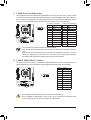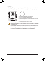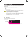
1
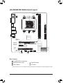
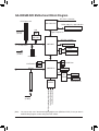
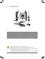
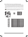
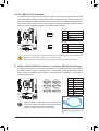
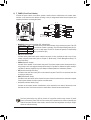
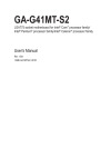
GA-880GM-D2H User's Manual Rev. 4001 12ME-880GD2H-4001R Motherboard GA-880GM-D2H Sept. 9, 2011 GA-880GM-D2H Motherboard Sept. 9, 2011 Copyright © 2011 GIGA-BYTE TECHNOLOGY CO., LTD. All rights reserved. The trademarks mentioned in this manual are legally registered to their respective owners. Disclaimer Information in this manual is protected by copyright laws and is the property of GIGABYTE. Changes to the specifications and features in this manual may be made by GIGABYTE without prior notice. No part of this manual may be reproduced, copied, translated, transmitted, or published in any form or by any means without GIGABYTE's prior written permission. In order to assist in the use of this product, carefully read the User's Manual. For product-related information, check on our website at: http://www.gigabyte.com Identifying Your Motherboard Revision The revision number on your motherboard looks like this: "REV: X.X." For example, "REV: 1.0" means the revision of the motherboard is 1.0. Check your motherboard revision before updating motherboard BIOS, drivers, or when looking for technical information. Example: Table of Contents GA-880GM-D2H Motherboard Layout.............................................................................5 GA-880GM-D2H Motherboard Block Diagram................................................................6 Chapter 1 Hardware Installation......................................................................................7 1-1 1-2 1-3 1-4 1-5 1-6 1-7 Installation Precautions.................................................................................... 7 Product Specifications...................................................................................... 8 Installing the CPU and CPU Cooler............................................................... 10 Installing the Memory......................................................................................11 Installing an Expansion Card...........................................................................11 Back Panel Connectors.................................................................................. 12 Internal Connectors........................................................................................ 14 Chapter 2 BIOS Setup...................................................................................................21 2-1 2-2 2-3 2-4 2-5 2-6 2-7 2-8 2-9 2-10 2-11 2-12 2-13 2-14 Startup Screen................................................................................................ 21 The Main Menu............................................................................................... 22 MB Intelligent Tweaker(M.I.T.)........................................................................ 23 Standard CMOS Features.............................................................................. 27 Advanced BIOS Features............................................................................... 28 Integrated Peripherals.................................................................................... 30 Power Management Setup............................................................................. 32 PnP/PCI Configurations.................................................................................. 34 PC Health Status............................................................................................ 34 Load Fail-Safe Defaults.................................................................................. 35 Load Optimized Defaults................................................................................ 36 Set Supervisor/User Password...................................................................... 36 Save & Exit Setup........................................................................................... 37 Exit Without Saving........................................................................................ 37 Chapter 3 Drivers Installation........................................................................................38 Chapter 4 Appendix.......................................................................................................38 Configuring SATA Hard Drive(s)................................................................................ 38 Regulatory Statements.............................................................................................. 41 -4- GA-880GM-D2H Motherboard Layout CPU_FAN KB_MS VGA_DVI ATX_12V AM3+ HDMI ATX R_USB USB_LAN AUDIO DDR3_1 Atheros GbE LAN PCIEX16 iTE IT8720 GA-880GM-D2H PCIEX1 DDR3_2 AMD 880G F_AUDIO F_PANEL AMD SB710 BAT CODEC PCI M_BIOS B_BIOS CLR_CMOS F_USB2 COM F_USB1 SATA2_2 SATA2_5 SATA2_1 SATA2_4 SATA2_0 SATA2_3 SYS_FAN Box Contents GA-880GM-D2H motherboard Motherboard driver disk User's Manual Two SATA cables I/O Shield * The box contents above are for reference only and the actual items shall depend on the product package you obtain. -5- GA-880GM-D2H Motherboard Block Diagram CPU CLK+/- (200 MHz) 1 PCI Express x16 AM3+/AM3 CPU DDR3 1866(O.C.)/1600/1066 MHz Dual Channel Memory LAN PCIe CLK (100 MHz) Hyper Transport 3.0 RJ45 Atheros GbE LAN x16 PCI Express Bus x1 D-Sub AMD 880G DVI-D Switch PCIe CLK (100 MHz) GFX CLK (100 MHz) x1 HDMI (Note) (Note) 1 PCI Express x1 8 USB Ports 6 SATA 3Gb/s PCI Bus AMD SB710 Dual BIOS LPC Bus 1 PCI PCI CLK (33 MHz) MIC (Center/Subwoofer Speaker Out) Line-Out (Front Speaker Out) Line-In (Rear Speaker Out) CODEC iTE IT8720 COM Port PS/2 KB/Mouse (Note) You can use only one of the onboard digital graphics ports (HDMI and DVI-D) for out put when in the BIOS Setup program or when during the POST screens. -6- Chapter 1 1-1 Hardware Installation Installation Precautions The motherboard contains numerous delicate electronic circuits and components which can become damaged as a result of electrostatic discharge (ESD). Prior to installation, carefully read the user's manual and follow these procedures: •• Prior to installation, do not remove or break motherboard S/N (Serial Number) sticker or warranty sticker provided by your dealer. These stickers are required for warranty validation. •• Always remove the AC power by unplugging the power cord from the power outlet before installing or removing the motherboard or other hardware components. •• When connecting hardware components to the internal connectors on the motherboard, make sure they are connected tightly and securely. •• When handling the motherboard, avoid touching any metal leads or connectors. •• It is best to wear an electrostatic discharge (ESD) wrist strap when handling electronic components such as a motherboard, CPU or memory. If you do not have an ESD wrist strap, keep your hands dry and first touch a metal object to eliminate static electricity. •• Prior to installing the motherboard, please have it on top of an antistatic pad or within an electrostatic shielding container. •• Before unplugging the power supply cable from the motherboard, make sure the power supply has been turned off. •• Before turning on the power, make sure the power supply voltage has been set according to the local voltage standard. •• Before using the product, please verify that all cables and power connectors of your hardware components are connected. •• To prevent damage to the motherboard, do not allow screws to come in contact with the motherboard circuit or its components. •• Make sure there are no leftover screws or metal components placed on the motherboard or within the computer casing. •• Do not place the computer system on an uneven surface. •• Do not place the computer system in a high-temperature environment. •• Turning on the computer power during the installation process can lead to damage to system components as well as physical harm to the user. •• If you are uncertain about any installation steps or have a problem related to the use of the product, please consult a certified computer technician. -7- 1-2 Product Specifications CPU AM3+ Socket: - AMD AM3+ processor - AMD AM3 Phenom™ II processor/ AMD Athlon™ II processor (Go to GIGABYTE's website for the latest CPU support list.) Hyper Transport Bus Chipset Memory 5200 MT/s North Bridge: AMD 880G South Bridge: AMD SB710 2 x 1.5V DDR3 DIMM sockets supporting up to 8 GB of system memory Onboard Graphics *Due to Windows 32-bit operating system limitation, when more than 4 GB of physical memory is installed, the actual memory size displayed will be less than 4 GB. Dual channel memory architecture Support for DDR3 1866(O.C.)/1600/1066 MHz memory modules (Go to GIGABYTE's website for the latest supported memory speeds and memory modules.) North Bridge: - 1 x D-Sub port - 1 x DVI-D port, supporting a maximum resolution of 2560x1600 * The DVI-D port does not support D-Sub connection by adapter. * The resolution of 2560x1600 is supported only when Dual Link DVI mode is enabled. * Simultaneous output for DVI-D and HDMI is not supported. - 1 x HDMI port, supporting a maximum resolution of 1920x1200 Audio Realtek/VIA HD audio codec High Definition Audio 2/4/5.1/7.1-channel LAN *To enable 7.1-channel audio, you have to use an HD front panel audio module and enable the multi-channel audio feature through the audio driver. 1 x Atheros GbE LAN chip (10/100/1000 Mbit) Expansion Slots 1 x PCI Express x16 slot, running at x16 1 x PCI Express x1 slot (All PCI Express slots conform to the PCI Express 2.0 standard.) 1 x PCI slot Storage Interface South Bridge: -6 x SATA 3Gb/s connectors supporting up to 6 SATA 3Gb/s devices -Support for SATA RAID 0, RAID 1, RAID 10, and JBOD USB South Bridge: -Up to 8 USB 2.0/1.1 ports (4 on the back panel, 4 via the USB brackets connected to the internal USB headers) Internal 1 x 24-pin ATX main power connector Connectors 1 x 4-pin ATX 12V power connector 6 x SATA 3Gb/s connectors 1 x CPU fan header 1 x system fan header 1 x front panel header -8- Internal Connectors Back Panel Connectors 1 x front panel audio header 2 x USB 2.0/1.1 headers 1 x serial port header 1 x clearing CMOS jumper 1 x PS/2 keyboard port 1 x PS/2 mouse port 1 x D-Sub port 1 x DVI-D port 1 x HDMI port 4 x USB 2.0/1.1 ports 1 x RJ-45 port 3 x audio jacks (Line In/Line Out/Microphone) I/O Controller iTE IT8720 chip Hardware Monitor System voltage detection CPU/System temperature detection CPU/System fan speed detection CPU overheating warning CPU/System fan fail warning CPU fan speed control BIOS Unique Features 2 x 16 Mbit flash Use of licensed AWARD BIOS Support for DualBIOS™ PnP 1.0a, DMI 2.0, SM BIOS 2.4, ACPI 1.0b Support for @BIOS Support for Q-Flash Support for Xpress BIOS Rescue Support for Download Center Support for Xpress Install Support for Xpress Recovery2 Support for EasyTune *Whether the CPU fan speed control function is supported will depend on the CPU cooler you install. * Available functions in EasyTune may differ by motherboard model. Support for Smart Recovery Support for Auto Green Support for ON/OFF Charge Support for Cloud OC Support for Q-Share -9- Bundled Software Operating System Form Factor Norton Internet Security (OEM version) Support for Microsoft® Windows 7/Vista/XP Micro ATX Form Factor; 24.4cm x 20.6cm *G IGABYTE reserves the right to make any changes to the product specifications and product-related information without prior notice. 1-3 Installing the CPU and CPU Cooler Read the following guidelines before you begin to install the CPU: • Make sure that the motherboard supports the CPU. (Go to GIGABYTE's website for the latest CPU support list.) • Always turn off the computer and unplug the power cord from the power outlet before installing the CPU to prevent hardware damage. • Locate the pin one of the CPU. The CPU cannot be inserted if oriented incorrectly. • Apply an even and thin layer of thermal grease on the surface of the CPU. • Do not turn on the computer if the CPU cooler is not installed, otherwise overheating and damage of the CPU may occur. • Set the CPU host frequency in accordance with the CPU specifications. It is not recommended that the system bus frequency be set beyond hardware specifications since it does not meet the standard requirements for the peripherals. If you wish to set the frequency beyond the standard specifications, please do so according to your hardware specifications including the CPU, graphics card, memory, hard drive, etc. Installing the CPU A. Locate the pin one (denoted by a small triangle) of the CPU socket and the CPU. A Small Triangle Mark Denotes Pin One of the Socket A Small Triangle Marking Denotes CPU Pin One - 10 - AM3+ Socket AM3+/AM3 CPU 1-4 Installing the Memory Read the following guidelines before you begin to install the memory: •• Make sure that the motherboard supports the memory. It is recommended that memory of the same capacity, brand, speed, and chips be used. (Go to GIGABYTE's website for the latest supported memory speeds and memory modules.) •• Always turn off the computer and unplug the power cord from the power outlet before installing the memory to prevent hardware damage. •• Memory modules have a foolproof design. A memory module can be installed in only one direction. If you are unable to insert the memory, switch the direction. Dual Channel Memory Configuration DDR3_1 DDR3_2 This motherboard provides two DDR3 memory sockets and supports Dual Channel Technology. After the memory is installed, the BIOS will automatically detect the specifications and capacity of the memory. Enabling Dual Channel memory mode will double the original memory bandwidth. The two DDR3 memory sockets are divided into two channels and each channel has one memory socket as following: Channel 0: DDR3_1 Channel 1: DDR3_2 Due to CPU limitations, read the following guidelines before installing the memory in Dual Channel mode. 111 Dual Channel mode cannot be enabled if only one DDR3 memory module is installed. 222 When enabling Dual Channel mode with two memory modules, it is recommended that memory of the same capacity, brand, speed, and chips be used for optimum performance. 1-5 Installing an Expansion Card Read the following guidelines before you begin to install an expansion card: • Make sure the motherboard supports the expansion card. Carefully read the manual that came with your expansion card. • Always turn off the computer and unplug the power cord from the power outlet before installing an expansion card to prevent hardware damage. - 11 - 1-6 Back Panel Connectors PS/2 Keyboard and PS/2 Mouse Port Use the upper port (green) to connect a PS/2 mouse and the lower port (purple) to connect a PS/2 keyboard. D-Sub Port The D-Sub port supports a 15-pin D-Sub connector. Connect a monitor that supports D-Sub connection to this port. DVI-D Port (Note 1) (Note 2) The DVI-D port conforms to the DVI-D specification and supports a maximum resolution of 2560x1600. Connect a monitor that supports DVI-D connection to this port. Please note that the actual resolutions supported are dependent on the monitor being used and the resolution of 2560x1600 is supported only when Dual Link DVI mode is enabled. The DisplayPort, D-Sub, and HDMI ports will be disabled when Dual Link DVI mode is enabled (refer to Chapter 2, "BIOS Setup," "Advanced BIOS Features," "IGX Configuration," for more information). HDMI Port (Note 2) HDMI (High-Definition Multimedia Interface) is an all-digital audio/video interface capable of transmitting uncompressed audio/video signals. The HDMI port is HDCP compliant and supports Dolby TrueHD and DTS HD Master Audio formats. It also supports up to 192KHz/24bit 8-channel LPCM audio output. You can use this port to connect your HDMI-supported monitor. The maximum supported resolution is 1920x1200, but the actual resolutions supported are dependent on the monitor being used. After installing the HDMI device, make sure to set the default sound playback device to HDMI. (The item name may differ depending on your operating system. The screenshot below is from Windows 7.) In Windows 7, select Start>Control Panel>Hardware and Sound>Sound>Playback, set Realtek HDMI Output - ATI HDMI Audio to the default playback device. •• When removing the cable connected to a back panel connector, first remove the cable from your device and then remove it from the motherboard. •• When removing the cable, pull it straight out from the connector. Do not rock it side to side to prevent an electrical short inside the cable connector. (Note 1) The DVI-D port does not support D-Sub connection by adapter. (Note 2) Simultaneous output for DVI-D and HDMI is not supported. - 12 - USB 2.0/1.1 Port The USB port supports the USB 2.0/1.1 specification. Use this port for USB devices such as a USB keyboard/mouse, USB printer, USB flash drive and etc. RJ-45 LAN Port The Gigabit Ethernet LAN port provides Internet connection at up to 1 Gbps data rate. The following describes the states of the LAN port LEDs. Connection/ Speed LED Activity LED Connection/Speed LED: LAN Port State Orange Green Off Activity LED: Description 1 Gbps data rate 100 Mbps data rate 10 Mbps data rate State Description Blinking Data transmission or receiving is occurring Off No data transmission or receiving is occurring Line In Jack (Blue) The default line in jack. Use this audio jack for line in devices such as an optical drive, walkman, etc. Line Out Jack (Green) The default line out jack. Use this audio jack for a headphone or 2-channel speaker. This jack can be used to connect front speakers in a 4/5.1/7.1-channel audio configuration. Mic In Jack (Pink) The default Mic in jack. Microphones must be connected to this jack. To enable 7.1-channel audio, you have to use an HD front panel audio module and enable the multi-channel audio feature through the audio driver. - 13 - 1-7 Internal Connectors 1 3 2 6 7 11 5 10 1) 2) 3) 4) 5) 6) ATX_12V ATX CPU_FAN SYS_FAN SATA2_0/1/2/3/4/5 F_PANEL 9 4 8 7) 8) 9) 10) 11) F_AUDIO F_USB1/F_USB2 COM CLR_CMOS BAT Read the following guidelines before connecting external devices: •• First make sure your devices are compliant with the connectors you wish to connect. •• Before installing the devices, be sure to turn off the devices and your computer. Unplug the power cord from the power outlet to prevent damage to the devices. •• After installing the device and before turning on the computer, make sure the device cable has been securely attached to the connector on the motherboard. - 14 - 1/2) ATX_12V/ATX (2x2 12V Power Connector and 2x12 Main Power Connector) With the use of the power connector, the power supply can supply enough stable power to all the components on the motherboard. Before connecting the power connector, first make sure the power supply is turned off and all devices are properly installed. The power connector possesses a foolproof design. Connect the power supply cable to the power connector in the correct orientation. The 12V power connector mainly supplies power to the CPU. If the 12V power connector is not connected, the computer will not start. To meet expansion requirements, it is recommended that a power supply that can withstand high power consumption be used (500W or greater). If a power supply is used that does not provide the required power, the result can lead to an unstable or unbootable system. ATX_12V: 2 1 4 3 ATX_12V Pin No. 1 2 3 4 Definition GND GND +12V +12V ATX: 12 24 1 13 Pin No. 1 2 3 4 5 6 7 8 9 10 11 12 Definition Pin No. 3.3V 13 3.3V 14 GND 15 +5V 16 GND 17 +5V 18 GND 19 Power Good 20 5VSB (stand by +5V) 21 +12V 22 +12V (Only for 2x12-pin ATX) 23 3.3V (Only for 2x12-pin ATX) 24 ATX - 15 - Definition 3.3V -12V GND PS_ON (soft On/Off) GND GND GND -5V +5V +5V +5V (Only for 2x12-pin ATX) GND (Only for 2x12-pin ATX) 3/4) CPU_FAN/SYS_FAN (Fan Headers) The motherboard has a 4-pin CPU fan header (CPU_FAN), a 3-pin system fan header (SYS_FAN). Most fan headers possess a foolproof insertion design. When connecting a fan cable, be sure to connect it in the correct orientation (the black connector wire is the ground wire). The motherboard supports CPU fan speed control, which requires the use of a CPU fan with fan speed control design. For optimum heat dissipation, it is recommended that a system fan be installed inside the chassis. CPU_FAN: Pin No. 1 2 3 4 1 CPU_FAN Definition GND +12V Sense Speed Control SYS_FAN: Pin No. 1 2 3 1 SYS_FAN Definition GND +12V Sense DEBUG PORT DEBUG PORT •• Be sure to connect fan cables to the fan headers to prevent your CPU and system from DEBUG overheating. OverDEBUG PORT PORT heating may result in damage to the CPU or the system may hang. •• These fan headers are not configuration jumper blocks. Do not place a jumper cap on theDEBUG headers. DEBUG PORT PORT 5) SATA2_0/1/2/3/4/5 (SATA 3Gb/s Connectors, Controlled by AMD SB710 South Bridge) The SATA connectors conform to SATA 3Gb/s standard and are compatible with SATA 1.5Gb/s standard. Each SATA connector supports a single SATA device. The AMD SB710 South Bridge supports RAID 0, RAID 1, RAID 10, and JBOD. Refer to Chapter 5, "Configuring SATA Hard Drive(s)," for instructions on configuring a RAID array. SATA2_2 SATA2_5 SATA2_1 SATA2_4 SATA2_0 SATA2_3 7 1 7 1 7 1 • A RAID 0 or RAID 1 configuration requires at least two hard drives. If more than two hard drives are to be used, the total number of hard drives must be an even number. • A RAID 10 configuration requires four hard drives. - 16 - Pin No. 1 2 3 4 5 6 7 Definition GND TXP TXN GND RXN RXP GND Please connect the L-shaped end of the SATA cable to your SATA hard drive. 6) F_PANEL (Front Panel Header) Connect the power switch, reset switch, speaker, chassis intrusion switch/sensor and system status indicator on the chassis to this header according to the pin assignments below. Note the positive and negative pins before connecting the cables. 20 19 SPEAK- PWR- Speaker PWR+ SPEAK+ Power Switch Message/Power/ Sleep LED CI+ CIRES+ RESHDHD+ PWPW+ MSGMSG+ Power LED Chassis Intrusion Header Reset Switch Hard Drive Activity LED 2 1 •• MSG/PWR (Message/Power/Sleep LED, Yellow/Purple): Connects to the power status indicator on the chassis front panel. The LED System Status LED is on when the system is operating. The LED keeps blinking when the sysS0 On S1 Blinking tem is in S1 sleep state. The LED is off when the system is in S3/S4 sleep S3/S4/S5 Off state or powered off (S5). •• PW (Power Switch, Red): Connects to the power switch on the chassis front panel. You may configure the way to turn off your system using the power switch (refer to Chapter 2, "BIOS Setup," "Power Management Setup," for more information). •• SPEAK (Speaker, Orange): Connects to the speaker on the chassis front panel. The system reports system startup status by issuing a beep code. One single short beep will be heard if no problem is detected at system startup. If a problem is detected, the BIOS may issue beeps in different patterns to indicate the problem. •• HD (Hard Drive Activity LED, Blue) Connects to the hard drive activity LED on the chassis front panel. The LED is on when the hard drive is reading or writing data. •• RES (Reset Switch, Green): Connects to the reset switch on the chassis front panel. Press the reset switch to restart the computer if the computer freezes and fails to perform a normal restart. •• CI (Chassis Intrusion Header, Gray): Connects to the chassis intrusion switch/sensor on the chassis that can detect if the chassis cover has been removed. This function requires a chassis with a chassis intrusion switch/sensor. The front panel design may differ by chassis. A front panel module mainly consists of power switch, reset switch, power LED, hard drive activity LED, speaker and etc. When connecting your chassis front panel module to this header, make sure the wire assignments and the pin assignments are matched correctly. - 17 - 7) F_AUDIO (Front Panel Audio Header) The front panel audio header supports Intel High Definition audio (HD) and AC'97 audio. You may connect your chassis front panel audio module to this header. Make sure the wire assignments of the module connector match the pin assignments of the motherboard header. Incorrect connection between the module connector and the motherboard header will make the device unable to work or even damage it. 2 1 10 9 For HD Front Panel Audio: Pin No. Definition 1 MIC2_L 2 GND 3 MIC2_R 4 -ACZ_DET 5 LINE2_R 6 GND 7 FAUDIO_JD 8 No Pin 9 LINE2_L 10 GND For AC'97 Front Panel Audio: Pin No. Definition 1 MIC 2 GND 3 MIC Power 4 NC 5 Line Out (R) 6 NC 7 NC 8 No Pin 9 Line Out (L) 10 NC •• The front panel audio header supports HD audio by default. •• Audio signals will be present on both of the front and back panel audio connections simultaneously. •• Some chassis provide a front panel audio module that has separated connectors on each wire instead of a single plug. For information about connecting the front panel audio module that has different wire assignments, please contact the chassis manufacturer. 8) F_USB1/F_USB2 (USB 2.0/1.1 Headers) The headers conform to USB 2.0/1.1 specification. Each USB header can provide two USB ports via an optional USB bracket. For purchasing the optional USB bracket, please contact the local dealer. 9 10 1 2 Pin No. 1 2 3 4 5 6 7 8 9 10 Definition Power (5V) Power (5V) USB DXUSB DYUSB DX+ USB DY+ GND GND No Pin NC •• Do not plug the IEEE 1394 bracket (2x5-pin) cable into the USB header. •• Prior to installing the USB bracket, be sure to turn off your computer and unplug the power cord from the power outlet to prevent damage to the USB bracket. - 18 - 9) COM (Serial Port Header) The COM header can provide one serial port via an optional COM port cable. For purchasing the optional COM port cable, please contact the local dealer. 9 10 Pin No. 1 2 3 4 5 6 7 8 9 10 1 2 Definition NDCDNSIN NSOUT NDTRGND NDSRNRTSNCTSNRINo Pin 10) CLR_CMOS (Clearing CMOS Jumper) Use this jumper to clear the CMOS values (e.g. date information and BIOS configurations) and reset the CMOS values to factory defaults. To clear the CMOS values, place a jumper cap on the two pins to temporarily short the two pins or use a metal object like a screwdriver to touch the two pins for a few seconds. Open: Normal Short: Clear CMOS Values •• Always turn off your computer and unplug the power cord from the power outlet before clearing the CMOS values. •• After clearing the CMOS values and before turning on your computer, be sure to remove the jumper cap from the jumper. Failure to do so may cause damage to the motherboard. •• After system restart, go to BIOS Setup to load factory defaults (select Load Optimized Defaults) or manually configure the BIOS settings (refer to Chapter 2, "BIOS Setup," for BIOS configurations). - 19 - 11) BAT (Battery) The battery provides power to keep the values (such as BIOS configurations, date, and time information) in the CMOS when the computer is turned off. Replace the battery when the battery voltage drops to a low level, or the CMOS values may not be accurate or may be lost. You may clear the CMOS values by removing the battery: 111 Turn off your computer and unplug the power cord. 222 Gently remove the battery from the battery holder and wait for one minute. (Or use a metal object like a screwdriver to touch the positive and negative terminals of the battery holder, making them short for 5 seconds.) 333 Replace the battery. 444 Plug in the power cord and restart your computer. •• Always turn off your computer and unplug the power cord before replacing the battery. •• Replace the battery with an equivalent one. Danger of explosion if the battery is replaced with an incorrect model. •• Contact the place of purchase or local dealer if you are not able to replace the battery by yourself or uncertain about the battery model. •• When installing the battery, note the orientation of the positive side (+) and the negative side (-) of the battery (the positive side should face up). •• Used batteries must be handled in accordance with local environmental regulations. - 20 - Chapter 2 BIOS Setup To access the BIOS Setup program, press the <Delete> key during the POST when the power is turned on. To see more advanced BIOS Setup menu options, you can press <Ctrl> + <F1> in the main menu of the BIOS Setup program. To upgrade the BIOS, use either the GIGABYTE Q-Flash or @BIOS utility. •• Q-Flash allows the user to quickly and easily upgrade or back up BIOS without entering the operating system. •• @BIOS is a Windows-based utility that searches and downloads the latest version of BIOS from the Internet and updates the BIOS. •• Because BIOS flashing is potentially risky, if you do not encounter problems using the current version of BIOS, it is recommended that you not flash the BIOS. To flash the BIOS, do it with caution. Inadequate BIOS flashing may result in system malfunction. •• It is recommended that you not alter the default settings (unless you need to) to prevent system instability or other unexpected results. Inadequately altering the settings may result in system's failure to boot. If this occurs, try to clear the CMOS values and reset the board to default values. (Refer to the "Load Optimized Defaults" section in this chapter or introductions of the battery/ clearing CMOS jumper in Chapter 1 for how to clear the CMOS values.) 2-1 Startup Screen The following screens may appear when the computer boots. The POST Screen Award Modular BIOS v6.00PG Copyright (C) 1984-2011, Award Software, Inc. Motherboard Model BIOS Version GA-880GM-D2H E8c . . . . <DEL>: BIOS Setup <F9>: XpressRecovery2 <F12>: Boot Menu <End>: Qflash 08/23/2011-RS880P-SB710-7A66BG0VC-00 - 21 - Function Keys 2-2 The Main Menu Once you enter the BIOS Setup program, the Main Menu (as shown below) appears on the screen. Use arrow keys to move among the items and press <Enter> to accept or enter a sub-menu. (Sample BIOS Version: E8c) CMOS Setup Utility-Copyright (C) 1984-2011 Award Software MB Intelligent Tweaker(M.I.T.) Standard CMOS Features Advanced BIOS Features Integrated Peripherals Power Management Setup PnP/PCI Configurations PC Health Status ESC: Quit F8: Q-Flash Load Fail-Safe Defaults Load Optimized Defaults Set Supervisor Password Set User Password Save & Exit Setup Exit Without Saving : Select Item F10: Save & Exit Setup F11: Save CMOS to BIOS F12: Load CMOS from BIOS Change CPU's Clock & Voltage •• If you do not find the settings you want in the Main Menu or a submenu, press <Ctrl>+<F1> to access more advanced options. •• When the system is not stable as usual, select the Load Optimized Defaults item to set your system to its defaults. •• The BIOS Setup menus described in this chapter are for reference only and may differ by BIOS version. The Functions of the <F11> and <F12> keys (For the Main Menu Only) F11: Save CMOS to BIOS This function allows you to save the current BIOS settings to a profile. You can create up to 8 profiles (Profile 1-8) and name each profile. First enter the profile name (to erase the default profile name, use the SPACE key) and then press <Enter> to complete. F12: Load CMOS from BIOS If your system becomes unstable and you have loaded the BIOS default settings, you can use this function to load the BIOS settings from a profile created before, without the hassles of reconfiguring the BIOS settings. First select the profile you wish to load, then press <Enter> to complete. - 22 - 2-3 MB Intelligent Tweaker(M.I.T.) CMOS Setup Utility-Copyright (C) 1984-2011 Award Software MB Intelligent Tweaker(M.I.T.) } IGX Configuration CPU Clock Ratio CPU NorthBridge Freq. Core Performance Boost (Note) CPB Ratio (Note) Turbo CPB (Note) CPU Host Clock Control x CPU Frequency(MHz) PCIE Clock(MHz) HT Link Width HT Link Frequency Set Memory Clock x Memory Clock } DRAM Configuration ******** System Voltage Optimized ******** System Voltage Control x DDR3 Voltage control x NorthBridge Volt Control x SouthBridge Volt Control x CPU NB VID Control x CPU Voltage Control Normal CPU Vcore Enter: Select : Move F5: Previous Values [Press Enter] [Auto] [Auto] [Enabled] [Auto] [Disabled] [Auto] 200 [Auto] [Auto] [Auto] [Auto] x6.66 [Press Enter] Item Help Menu Level 2800Mhz 2000Mhz 3100Mhz 2000Mhz 1333Mhz [Auto] Auto Auto Auto Auto Auto 1.2750V +/-/PU/PD: Value F10: Save F6: Fail-Safe Defaults ESC: Exit F1: General Help F7: Optimized Defaults • Whether the system will work stably with the overclock/overvoltage settings you made is dependent on your overall system configurations. Incorrectly doing overclock/overvoltage may result in damage to CPU, chipset, or memory and reduce the useful life of these components. This page is for advanced users only and we recommend you not to alter the default settings to prevent system instability or other unexpected results. (Inadequately altering the settings may result in system's failure to boot. If this occurs, clear the CMOS values and reset the board to default values.) • When the System Voltage Optimized item blinks in red, it is recommended that you set the System Voltage Control item to Auto to optimize the system voltage settings. IGX Configuration CMOS Setup Utility-Copyright (C) 1984-2011 Award Software IGX Configuration Internal Graphics Mode UMA Frame Buffer Size x Surround View VGA Core Clock control x VGA Core Clock(MHz) Enter: Select : Move F5: Previous Values [UMA] [Auto] Disabled [Auto] 560 +/-/PU/PD: Value F10: Save F6: Fail-Safe Defaults Item Help Menu Level ESC: Exit F1: General Help F7: Optimized Defaults Internal Graphics Mode Allows you to determine whether to allocate system memory for the onboard graphics controller. Disabled Disables the onboard graphics controller. UMA Allocates memory for the onboard graphics controller from the system memory. (Default) UMA Frame Buffer Size Frame buffer size is the total amount of system memory allocated solely for the onboard graphics controller. MS-DOS, for example, will use only this memory for display. Options are: Auto (default), 128MB, 256MB, 512MB. (Note) This item is present only when you install a CPU that supports this feature. - 23 - Surround View Enables or disables the Surround View function. This option is configurable only when Init Display First under Advanced BIOS Features is set to PEG and an ATI graphics card is installed. (Default: Disabled) VGA Core Clock control Allows you to determine whether to manually set the VGA Core clock. (Default: Auto) VGA Core Clock(MHz) Allows you to manually set the VGA Core clock. The adjustable range is from 200 MHz to 2000 MHz. This item is configurable only when the VGA Core Clock control option is set to Manual. CPU Clock Ratio Allows you to alter the clock ratio for the installed CPU. The adjustable range is dependent on the CPU being used. CPU NorthBridge Freq. Allows you to alter the North Bridge controller frequency for the installed CPU. The adjustable range is dependent on the CPU being used. Core Performance Boost (Note) Allows you to determine whether to enable the Core Performance Boost (CPB) technology, a CPU performance-boost technology. (Default: Enabled) CPB Ratio (Note) Allows you alter the ratio for the CPB. The adjustable range is dependent on the CPU being installed. (Default: Auto) Turbo CPB (Note) Allows you to determine whether to improve CPU performance. (Default: Disabled) CPU Host Clock Control Enables or disables the control of CPU host clock. Auto (default) allows the BIOS to automatically adjust the CPU host frequency. Manual allows the CPU Frequency (MHz) item below to be configurable. Note: If your system fails to boot after overclocking, please wait for 20 seconds to allow for automated system reboot, or clear the CMOS values to reset the board to default values. CPU Frequency(MHz) Allows you to manually set the CPU host frequency. The adjustable range is from 200 MHz to 500 MHz. This option is configurable only when CPU Host Clock Control is set to Manual.Important It is highly recommended that the CPU frequency be set in accordance with the CPU specifications. PCIE Clock(MHz) Allows you to manually set the PCIe clock frequency. The adjustable range is from 100 MHz to 150 MHz. Auto sets the PCIe clock frequency to standard 100 MHz. (Default: Auto) HT Link Width Allows you to manually set the width for the HT Link between the CPU and chipset. Auto BIOS will automatically adjust the HT Link Width. (Default) 8 bit Sets HT Link Width to 8 bit. 16 bit Sets HT Link Width to 16 bit. HT Link Frequency Allows you to manually set the frequency for the HT Link between the CPU and chipset. Auto BIOS will automatically adjust the HT Link Frequency. (Default) x1~x10 Sets HT Link Frequency to x1~x10 (200 MHz~2.0 GHz). Set Memory Clock Determines whether to manually set the memory clock. Auto lets BIOS automatically set the memory clock as required. Manual allows the memory clock control item below to be configurable. (Default: Auto) (Note) This item is present only when you install a CPU that supports this feature. - 24 - Memory Clock This option is configurable only when Set Memory Clock is set to Manual. X4.00 Sets Memory Clock to X4.00. X5.33 Sets Memory Clock to X5.33. X6.66 Sets Memory Clock to X6.66. X8.00 Sets Memory Clock to X8.00. DRAM Configuration CMOS Setup Utility-Copyright (C) 1984-2011 Award Software DRAM Configuration x x x x x x x x x x x x DCTs Mode DDR3 Timing Items 1T/2T Command Timing CAS# latency RAS to CAS R/W Delay Row Precharge Time Minimum RAS Active Time TwTr Command Delay Trfc0 for DIMM1 Trfc1 for DIMM2 Write Recovery Time Precharge Time Row Cycle Time RAS to RAS Delay [Unganged] [Auto] SPD Auto -Auto 9T Auto 9T Auto 9T Auto 24T Auto 5T Auto 110ns Auto -Auto 10T Auto 5T Auto 33T Auto 4T Channel Interleaving Bank Interleaving DQS Training Control Memclock tri-stating [Enabled] [Enabled] [Skip DQS] [Disabled] Enter: Select : Move F5: Previous Values Auto -9T 9T 9T 24T 5T 110ns -10T 5T 33T 4T +/-/PU/PD: Value F10: Save F6: Fail-Safe Defaults DCTs Mode Item Help Menu Level ESC: Exit F1: General Help F7: Optimized Defaults Allows you to set memory control mode. Ganged Sets memory control mode to single dual-channel. Unganged Sets memory control mode to two single-channel. (Default) DDR3 Timing Items Manual allows all DDR3 Timing items below to be configurable. Options are: Auto (default), Manual. 1T/2T Command Timing Options are: Auto (default), 1T, 2T. CAS# latency Options are: Auto (default), 4T~12T. RAS to CAS R/W Delay Options are: Auto (default), 5T~12T. Row Precharge Time Options are: Auto (default), 5T~12T. Minimum RAS Active Time Options are: Auto (default), 15T~30T. TwTr Command Delay Options are: Auto (default), 4T~7T. Trfc0 for DIMM1 Options are: Auto (default), 90ns, 110ns, 160ns, 300ns, 350ns. - 25 - Trfc1 for DIMM2 Options are: Auto (default), 90ns, 110ns, 160ns, 300ns, 350ns. Write Recovery Time Options are: Auto (default), 5T~8T, 10T, 12T. Precharge Time Options are: Auto (default), 4T~7T. Row Cycle Time Options are: Auto (default), 11T~42T. RAS to RAS Delay Options are: Auto (default), 4T~7T. Channel Interleaving Enables or disables memory channel interleaving. Enabled allows the system to simultaneously access different channels of the memory to increase memory performance and stability. (Default: Enabled) Bank Interleaving Enables or disables memory bank interleaving. Enabled allows the system to simultaneously access different banks of the memory to increase memory performance and stability. (Default: Enabled) DQS Training Control Enables or disables memory DQS training each time the system restarts. (Default: Skip DQS) Memclock tri-stating Determines whether to enable memory clock tri-stating in CPU C3 or Alt VID mode. (Default: Disabled) ******** System Voltage Optimized ******** System Voltage Control Determines whether to manually set the system voltages. Auto lets the BIOS automatically set the system voltages as required. Manual allows all voltage control items below to be configurable. (Default: Auto) DDR3 Voltage Control Allows you to set memory voltage. Normal Supplies the memory voltage as required. (Default) +0.100V ~ +0.300V The adjustable range is from 0.100V to 0.300V. Note: Increasing memory voltage may result in damage to the memory. NorthBridge Volt Control Allows you to set the North Bridge voltage. Normal Supplies the North Bridge voltage as required. (Default) +0.1V ~ +0.3V The adjustable range is from 0.1V to 0.3V. SouthBridge Volt Control Allows you to set the South Bridge voltage. Normal Supplies the South Bridge voltage as required. (Default) +0.1V ~ +0.2V The adjustable range is from 0.1 to 0.2V. CPU NB VID Control Allows you to set the CPU North Bridge VID voltage. Auto sets the CPU North Bridge VID voltage as required. The adjustable range is dependent on the CPU being installed. (Default: Normal) Note: Increasing CPU voltage may result in damage to your CPU or reduce the useful life of the CPU. - 26 - CPU Voltage Control Allows you to set the CPU voltage. Auto sets the CPU voltage as required. The adjustable range is dependent on the CPU being installed. (Default: Normal) Note: Increasing CPU voltage may result in damage to your CPU or reduce the useful life of the CPU. Normal CPU Vcore Displays the normal operating voltage of your CPU. 2-4 Standard CMOS Features CMOS Setup Utility-Copyright (C) 1984-2011 Award Software Standard CMOS Features } } } } } } Date (mm:dd:yy) Time (hh:mm:ss) Tue, Aug 23 2011 22:31:24 IDE Channel 0 Master IDE Channel 0 Slave IDE Channel 1 Master IDE Channel 1 Slave IDE Channel 2 Master IDE Channel 2 Slave [None] [None] [None] [None] [None] [None] Halt On [All, But Keyboard] Base Memory Extended Memory 640K 766M Enter: Select : Move F5: Previous Values +/-/PU/PD: Value F10: Save F6: Fail-Safe Defaults Item Help Menu Level ESC: Exit F1: General Help F7: Optimized Defaults Date (mm:dd:yy) Sets the system date. Time (hh:mm:ss) Sets the system time. IDE Channel 0, 1 Master/Slave IDE Channel 0, 1 Master/Slave Configure your SATA devices by using one of the three methods below: •• NoneIf no SATA devices are used, set this item to None so the system will skip the detection of the device during the POST for faster system startup. •• Auto Lets the BIOS automatically detect SATA devices during the POST. (Default) •• ManualAllows you to manually enter the specifications of the hard drive when the hard drive access mode is set to CHS. Access Mode Sets the hard drive access mode. Options are: Auto (default), CHS, LBA, Large. IDE Channel 2 Master/Slave Extended IDE Drive Configure your SATA devices by using one of the two methods below: •• Auto Lets the BIOS automatically detect SATA devices during the POST. (Default) •• NoneIf no SATA devices are used, set this item to None so the system will skip the detection of the device during the POST for faster system startup. Access Mode Sets the hard drive access mode. Options are: Auto (default), Large. - 27 - The following fields display your hard drive specifications. If you wish to enter the parameters manually, refer to the information on the hard drive. Capacity Approximate capacity of the currently installed hard drive. Halt On Allows you to determine whether the system will stop for an error during the POST. Options are: "All Errors," "No Errors," "All, But Keyboard". (Default) Memory These fields are read-only and are determined by the BIOS POST. 2-5 Advanced BIOS Features CMOS Setup Utility-Copyright (C) 1984-2011 Award Software Advanced BIOS Features } IGX Configuration AMD C1E Support Virtualization AMD K8 Cool&Quiet control CPU Unlock (Note) CPU core Control x CPU core 0 x CPU core 1 x CPU core 2 (Note) x CPU core 3 (Note) x CPU core 4 (Note) x CPU core 5 (Note) } Hard Disk Boot Priority EFI CD/DVD Boot Option First Boot Device Second Boot Device Third Boot Device Password Check HDD S.M.A.R.T. Capability Away Mode Backup BIOS Image to HDD Init Display First Enter: Select : Move F5: Previous Values [Press Enter] [Auto] [Disabled] [Auto] [Disabled] [Auto] Enabled Enabled Enabled Enabled Enabled Enabled [Press Enter] [Auto] [Hard Disk] [CDROM] [USB-HDD] [Setup] [Disabled] [Disabled] [Disabled] [PCI Slot] +/-/PU/PD: Value F10: Save F6: Fail-Safe Defaults Item Help Menu Level ESC: Exit F1: General Help F7: Optimized Defaults IGX Configuration The settings in this submenu are synchronous to those under the same items on the MB Intelligent Tweaker(M.I.T.) main menu. AMD C1E Support Enables or disables the C1E CPU power-saving function in system halt state. When enabled, the power consumption will be reduced during system halt state. Auto If a CPU that supports hardware C1E is installed, the BIOS will automatically enable the hardware C1E function. If not, the C1E function will be disabled. (Default) Enabled If a CPU that supports hardware C1E is installed, the BIOS will automatically enable the hardware C1E function. If not, the BIOS will enable the software C1E function. Disabled Disables the C1E function. Virtualization Virtualization allows a platform to run multiple operating systems and applications in independent partitions. With virtualization, one computer system can function as multiple virtual systems. (Default: Disabled) (Note) This item is present only when you install a CPU that supports this feature. - 28 - AMD K8 Cool&Quiet control Auto Lets the AMD Cool'n'Quiet driver dynamically adjust the CPU clock and VID to reduce heat output from your computer and its power consumption. (Default) Disabled Disables this function. CPU Unlock (Note) Allows you to determine whether unlock hidden CPU cores. (Default: Disabled) CPU core Control Allows you to determine whether to manually enable/disable CPU Core 1/2/3/4/5. AutoLets the BIOS to enable all CPU cores (number of cores available depends on the CPU being used). (Default) Manual Allows you to individually enable/disable CPU Core 1/2/3/4/5. CPU core 0 This setting is fixed. CPU Core 0 is always enabled. CPU core 1, 2/3/4/5 (Note) Enables or disables CPU Core 1/2/3/4/5. (Default: Enabled) Hard Disk Boot Priority Specifies the sequence of loading the operating system from the installed hard drives. Use the up or down arrow key to select a hard drive, then press the plus key <+> (or <PageUp>) or the minus key <-> (or <PageDown>) to move it up or down on the list. Press <Esc> to exit this menu when finished. EFI CD/DVD Boot Option Set this item to EFI if you want to install the operating system to a hard drive larger than 2.2 TB. Make sure the operating system to be installed supports booting from a GPT partition, such as Windows 7 64bit and Windows Server 2003 64-bit. Auto lets the BIOS automatically configure this setting depending on the hard drive you install. (Default: Auto) First/Second/Third Boot Device Specifies the boot order from the available devices. Use the up or down arrow key to select a device and press <Enter> to accept. Options are: LS120, Hard Disk, CDROM, ZIP, USB-FDD, USB-ZIP, USBCDROM, USB-HDD, Legacy LAN, Disabled. Password Check Specifies whether a password is required every time the system boots, or only when you enter BIOS Setup. After configuring this item, set the password(s) under the Set Supervisor/User Password item in the BIOS Main Menu. Setup A password is only required for entering the BIOS Setup program. (Default) System A password is required for booting the system and for entering the BIOS Setup program. HDD S.M.A.R.T. Capability Enables or disables the S.M.A.R.T. (Self Monitoring and Reporting Technology) capability of your hard drive. This feature allows your system to report read/write errors of the hard drive and to issue warnings when a third party hardware monitor utility is installed. (Default: Disabled) Away Mode Enables or disables Away Mode in Windows XP Media Center operating system. Away Mode allows the system to silently perform unattended tasks while in a low-power mode that appears off. (Default: Disabled) (Note) This item is present only when you install a CPU that supports this feature. - 29 - Backup BIOS Image to HDD Allows the system to copy the BIOS image file to the hard drive. If the system BIOS is corrupted, it will be recovered from this image file. (Default: Disabled) Init Display First Specifies the first initiation of the monitor display from the installed PCI graphics card, PCI Express graphics card, or the onboard graphics. PCI Slot Sets the PCI graphics card as the first display. (Default) OnChipVGA Sets the onboard graphics as the first display. PEG Sets the PCI Express graphics card on the PCIEX16 slot as the first display. 2-6 Integrated Peripherals CMOS Setup Utility-Copyright (C) 1984-2011 Award Software Integrated Peripherals OnChip SATA Controller OnChip SATA Type x OnChip SATA Port4/5 Type x OnChip SATA Port as ESP } SMART LAN Onboard LAN Function Onboard LAN Boot ROM Onboard Audio Function USB Controllers USB Legacy Function USB Storage Function Onboard Serial Port Enter: Select : Move F5: Previous Values Item Help Menu Level [Enabled] [Native IDE] IDE Press Enter [Press Enter] [Enabled] [Disabled] [Enabled] [Enabled] [Enabled] [Enabled] [3F8/IRQ4] +/-/PU/PD: Value F10: Save F6: Fail-Safe Defaults ESC: Exit F1: General Help F7: Optimized Defaults OnChip SATA Controller Enables or disables the integrated SATA controller. (Default: Enabled) OnChip SATA Type (SATA2_0~SATA2_3 connectors) Configures the operating mode of the integrated SATA2_0~SATA2_3 controller. Native IDE Allows the SATA controller to operate in Native IDE mode. (Default) Enable Native IDE mode if you wish to install operating systems that support Native mode. RAID Enables RAID for the SATA controller. AHCI Configures the SATA controllers to AHCI mode. Advanced Host Controller Interface (AHCI) is an interface specification that allows the storage driver to enable advanced Serial ATA features such as Native Command Queuing and hot plug. OnChip SATA Port4/5 Type (SATA2_4/SATA2_5 connectors) This option is configurable only when OnChip SATA Type is set to RAID or AHCI. Configures the operating mode of the integrated SATA2_4/SATA2_5 connectors. IDE Disables RAID for the SATA controller and configures the SATA controller to PATA mode. (Default) As SATA Type The mode depends on the OnChip SATA Type settings. - 30 - OnChip SATA Port as ESP CMOS Setup Utility-Copyright (C) 1984-2011 Award Software OnChip SATA Port as ESP Port0 as ESP Port1 as ESP Port2 as ESP Port3 as ESP x Port4 as ESP x Port5 as ESP Item Help Menu Level [Disabled] [Disabled] [Disabled] [Disabled] Disabled Disabled Enter: Select : Move F5: Previous Values +/-/PU/PD: Value F10: Save F6: Fail-Safe Defaults ESC: Exit F1: General Help F7: Optimized Defaults Port0 as ESP/Port1 as ESP/Port2 as ESP/Port3 as ESP This option is configurable only when OnChip SATA Type is set to AHCI. Enabled will speed up the hot plug detection of the connected SATA device. (Default: Disabled) Port4 as ESP/Port5 as ESP This option is configurable only when OnChip SATA Type is set to AHCI and OnChip SATA Type Port4/5 is set to As SATA Type. Enabled will speed up the hot plug detection of the connected SATA device. (Default: Disabled) SMART LAN (LAN Cable Diagnostic Function) CMOS Setup Utility-Copyright (C) 1984-2011 Award Software SMART LAN Start detecting at Port..... Part1-2 Status = Open Part3-6 Status = Open Part4-5 Status = Open Part7-8 Status = Open / / / / Length Length Length Length Enter: Select : Move F5: Previous Values = = = = Item Help Menu Level 0m 0m 0m 0m +/-/PU/PD: Value F10: Save F6: Fail-Safe Defaults ESC: Exit F1: General Help F7: Optimized Defaults This motherboard incorporates cable diagnostic feature designed to detect the status of the attached LAN cable. This feature will detect cabling issue and report the approximate distance to the fault or short. Refer to the following information for diagnosing your LAN cable: Onboard Audio Function Enables or disables the onboard audio function. (Default: Enabled) If you wish to install a 3rd party add-in audio card instead of using the onboard audio, set this item to Disabled. Onboard LAN Function Enables or disables the onboard LAN function. (Default: Enabled) If you wish to install a 3rd party add-in network card instead of using the onboard LAN, set this item to Disabled. Onboard LAN Boot ROM Allows you to decide whether to activate the boot ROM integrated with the onboard LAN chip. (Default: Disabled) - 31 - USB Controllers Enables or disables the integrated USB controllers. (Default: Enabled) Disabled will turn off all of the USB functionalities below. USB Legacy Function Allows USB keyboard to be used in MS-DOS. (Default: Enabled) USB Storage Function Determines whether to detect USB storage devices, including USB flash drives and USB hard drives during the POST. (Default: Enabled) Onboard Serial Port Enables or disables the first serial port and specifies its base I/O address and corresponding interrupt. Options are: Auto, 3F8/IRQ4 (default), 2F8/IRQ3, 3E8/IRQ4, 2E8/IRQ3, Disabled. 2-7 Power Management Setup CMOS Setup Utility-Copyright (C) 1984-2011 Award Software Power Management Setup ACPI Suspend Type Soft-Off by Power button USB Wake Up from S3 Modem Ring Resume PME Event Wake Up HPET Support (Note) Power On By Mouse Power On By Keyboard x KB Power ON Password AC Back Function Power-On by Alarm x Date (of Month) x Resume Time (hh:mm:ss) ErP Support Enter: Select : Move F5: Previous Values [S3(STR)] [Instant-off] [Enabled] [Disabled] [Enabled] [Enabled] [Disabled] [Disabled] Enter [Soft-Off] [Disabled] Everyday 0:0:0 [Disabled] +/-/PU/PD: Value F10: Save F6: Fail-Safe Defaults Item Help Menu Level ESC: Exit F1: General Help F7: Optimized Defaults ACPI Suspend Type Specifies the ACPI sleep state when the system enters suspend. S1(POS)Enables the system to enter the ACPI S1 (Power on Suspend) sleep state. In S1 sleep state, the system appears suspended and stays in a low power mode. The system can be resumed at any time. S3(STR)Enables the system to enter the ACPI S3 (Suspend to RAM) sleep state (default). In S3 sleep state, the system appears to be off and consumes less power than in the S1 state. When signaled by a wake-up device or event, the system resumes to its working state exactly where it was left off. Soft-Off by Power button Configures the way to turn off the computer in MS-DOS mode using the power button. Instant-Off Press the power button and then the system will be turned off instantly. (Default) Delay 4 Sec.Press and hold the power button for 4 seconds to turn off the system. If the power button is pressed for less than 4 seconds, the system will enter suspend mode. (Note) Supported on Windows 7/Vista operating system only. - 32 - USB Wake Up from S3 Allows the system to be awakened from ACPI S3 sleep state by a wake-up signal from the installed USB device. (Default: Enabled) Modem Ring Resume Allows the system to be awakened from an ACPI sleep state by a wake-up signal from a modem that supports wake-up function. (Default: Disabled) PME Event Wake Up Allows the system to be awakened from an ACPI sleep state by a wake-up signal from a PCI or PCIe device. Note: To use this function, you need an ATX power supply providing at least 1A on the +5VSB lead. (Default: Enabled) HPET Support (Note) Enables or disables High Precision Event Timer (HPET) for Windows 7/Vista operating system. (Default: Enabled) Power On By Mouse Allows the system to be turned on by a PS/2 mouse wake-up event. Note: To use this function, you need an ATX power supply providing at least 1A on the +5VSB lead. Disabled Disables this function. (Default) Double Click Double click on left button on the PS/2 mouse to turn on the system. Power On By Keyboard Allows the system to be turned on by a PS/2 keyboard wake-up event. Note: you need an ATX power supply providing at least 1A on the +5VSB lead. Disabled Disables this function. (Default) Password Set a password with 1~5 characters to turn on the system. Any KEY Press any key on the keyboard to turn on the system. Keyboard 98 Press POWER button on the Windows 98 keyboard to turn on the system. KB Power ON Password Set the password when Power On by Keyboard is set to Password. Press <Enter> on this item and set a password with up to 5 characters and then press <Enter> to accept. To turn on the system, enter the password and press <Enter>. Note: To cancel the password, press <Enter> on this item. When prompted for the password, press <Enter> again without entering the password to clear the password settings. AC Back Function Determines the state of the system after the return of power from an AC power loss. Soft-Off The system stays off upon the return of the AC power. (Default) Full-On The system is turned on upon the return of the AC power. Memory The system returns to its last known awake state upon the return of the AC power. Power-On by Alarm Determines whether to power on the system at a desired time. (Default: Disabled) If enabled, set the date and time as following: Date (of Month): Turn on the system at a specific time on each day or on a specific day in a month. Resume Time (hh: mm: ss): Set the time at which the system will be powered on automatically. Note: When using this function, avoid inadequate shutdown from the operating system or removal of the AC power, or the settings may not be effective. (Note) Supported on Windows 7/Vista operating system only. - 33 - ErP Support Determines whether to let the system consume less than 1W power in S5 (shutdown) state. (Default: Disabled) Note: When this item is set to Enabled, the following four functions will become unavailable: PME event wake up, power on by mouse, power on by keyboard, and wake on LAN. 2-8 PnP/PCI Configurations CMOS Setup Utility-Copyright (C) 1984-2011 Award Software PnP/PCI Configurations PCI1 IRQ Assignment Enter: Select : Move F5: Previous Values PCI1 IRQ Assignment Auto 3,4,5,7,9,10,11,12,14,15 2-9 Item Help Menu Level [Auto] +/-/PU/PD: Value F10: Save F6: Fail-Safe Defaults ESC: Exit F1: General Help F7: Optimized Defaults BIOS auto-assigns IRQ to the first PCI slot. (Default) Assigns IRQ 3,4,5,7,9,10,11,12,14,15 to the first PCI slot. PC Health Status CMOS Setup Utility-Copyright (C) 1984-2011 Award Software PC Health Status Hardware Thermal Control Reset Case Open Status Case Opened Vcore DDR3 1.5V +3.3V +12V Current System Temperature Current CPU Temperature Current CPU FAN Speed Current SYSTEM FAN Speed CPU Warning Temperature CPU FAN Fail Warning SYSTEM FAN Fail Warning CPU Smart FAN Control CPU Smart FAN Mode Enter: Select : Move F5: Previous Values [Enabled] [Disabled] No 1.264V 1.584V 3.312V 12.229V 36oC 48oC 1973 RPM 0 RPM [Disabled] [Disabled] [Disabled] [Enabled] [Auto] +/-/PU/PD: Value F10: Save F6: Fail-Safe Defaults Item Help Menu Level ESC: Exit F1: General Help F7: Optimized Defaults Hardware Thermal Control Enables or disables the CPU overheating protection function. When enabled, the CPU core voltage and ratio will be reduced when the CPU is overheated. (Default: Enabled) Reset Case Open Status Keeps or clears the record of previous chassis intrusion status. Enabled clears the record of previous chassis intrusion status and the Case Opened field will show "No" at next boot. (Default: Disabled) Case Opened Displays the detection status of the chassis intrusion detection device attached to the motherboard CI header. If the system chassis cover is removed, this field will show "Yes", otherwise it will show "No". To clear the chassis intrusion status record, set Reset Case Open Status to Enabled, save the settings to the CMOS, and then restart your system. - 34 - Current Voltage(V) Vcore/DDR3 1.5V/+3.3V/+12V Displays the current system voltages. Current System/CPU Temperature Displays current system/CPU temperature. Current CPU/SYSTEM FAN Speed (RPM) Displays current CPU/system fan speed. CPU Warning Temperature Sets the warning threshold for CPU temperature. When CPU temperature exceeds the threshold, BIOS will emit warning sound. Options are: Disabled (default), 60oC/140oF, 70oC/158oF, 80oC/176oF, 90oC/194oF. CPU/SYSTEM FAN Fail Warning Allows the system to emit warning sound if the CPU/system fan is not connected or fails. Check the fan condition or fan connection when this occurs. (Default: Disabled) CPU Smart FAN Control Enables or disables the CPU fan speed control function. Enabled allows the CPU fan to run at different speed according to the CPU temperature. You can adjust the fan speed with EasyTune based on system requirements. If disabled, the CPU fan runs at full speed. (Default: Enabled) CPU Smart FAN Mode Specifies how to control CPU fan speed. This item is configurable only when CPU Smart FAN Control is enabled. Auto Lets the BIOS automatically detect the type of CPU fan installed and sets the optimal CPU fan control mode. (Default) PWM Sets PWM mode for a 4-pin CPU fan. 2-10 Load Fail-Safe Defaults CMOS Setup Utility-Copyright (C) 1984-2011 Award Software MB Intelligent Tweaker(M.I.T.) Standard CMOS Features Advanced BIOS Features Integrated Peripherals Power Management Setup PnP/PCI Configurations PC Health Status ESC: Quit F8: Q-Flash Load Fail-Safe Defaults Load Optimized Defaults Set Supervisor Password Set User Password Save & Exit Setup Load Fail-Safe Defaults (Y/N)? N Exit Without Saving : Select Item F10: Save & Exit Setup F11: Save CMOS to BIOS F12: Load CMOS from BIOS Load Fail-Safe Defaults Press <Enter> on this item and then press the <Y> key to load the safest BIOS default settings. In case system instability occurs, you may try to load Fail-Safe defaults, which are the safest and most stable BIOS settings for the motherboard. - 35 - 2-11 Load Optimized Defaults CMOS Setup Utility-Copyright (C) 1984-2011 Award Software MB Intelligent Tweaker(M.I.T.) Load Fail-Safe Defaults Standard CMOS Features Load Optimized Defaults Advanced BIOS Features Set Supervisor Password Integrated Peripherals Set User Password Power Management Setup Save & Exit Setup Load Optimized Defaults (Y/N)? N PnP/PCI Configurations Exit Without Saving PC Health Status ESC: Quit F8: Q-Flash : Select Item F10: Save & Exit Setup F11: Save CMOS to BIOS F12: Load CMOS from BIOS Load Optimized Defaults Press <Enter> on this item and then press the <Y> key to load the optimal BIOS default settings. The BIOS defaults settings help the system to operate in optimum state. Always load the Optimized defaults after updating the BIOS or after clearing the CMOS values. 2-12 Set Supervisor/User Password CMOS Setup Utility-Copyright (C) 1984-2011 Award Software MB Intelligent Tweaker(M.I.T.) Standard CMOS Features Advanced BIOS Features Integrated Peripherals Power Management Setup Enter Password: PnP/PCI Configurations PC Health Status ESC: Quit F8: Q-Flash Load Fail-Safe Defaults Load Optimized Defaults Set Supervisor Password Set User Password Save & Exit Setup Exit Without Saving : Select Item F10: Save & Exit Setup F11: Save CMOS to BIOS F12: Load CMOS from BIOS Change/Set/Disable Password Press <Enter> on this item and type the password with up to 8 characters and then press <Enter>. You will be requested to confirm the password. Type the password again and press <Enter>. The BIOS Setup program allows you to specify two separate passwords: Supervisor Password When a system password is set and the Password Check item in Advanced BIOS Features is set to Setup, you must enter the supervisor password for entering BIOS Setup and making BIOS changes. When the Password Check item is set to System, you must enter the supervisor password (or user password) at system startup and when entering BIOS Setup. User Password When the Password Check item is set to System, you must enter the supervisor password (or user password) at system startup to continue system boot. In BIOS Setup, you must enter the supervisor password if you wish to make changes to BIOS settings. The user password only allows you to view the BIOS settings but not to make changes. To clear the password, press <Enter> on the password item and when requested for the password, press <Enter> again. The message "PASSWORD DISABLED" will appear, indicating the password has been cancelled. - 36 - 2-13 Save & Exit Setup CMOS Setup Utility-Copyright (C) 1984-2011 Award Software MB Intelligent Tweaker(M.I.T.) Load Fail-Safe Defaults Standard CMOS Features Load Optimized Defaults Advanced BIOS Features (Y/N)? SetYSupervisor Password Save to CMOS and EXIT Integrated Peripherals Set User Password Power Management Setup Save & Exit Setup PnP/PCI Configurations Exit Without Saving PC Health Status ESC: Quit F8: Q-Flash : Select Item F10: Save & Exit Setup F11: Save CMOS to BIOS F12: Load CMOS from BIOS Save Data to CMOS Press <Enter> on this item and press the <Y> key. This saves the changes to the CMOS and exits the BIOS Setup program. Press <N> or <Esc> to return to the BIOS Setup Main Menu. 2-14 Exit Without Saving CMOS Setup Utility-Copyright (C) 1984-2011 Award Software MB Intelligent Tweaker(M.I.T.) Standard CMOS Features Advanced BIOS Features Integrated Peripherals Load Fail-Safe Defaults Load Optimized Defaults Quit Without Saving (Y/N)?Set N Supervisor Password Set User Password Power Management Setup PnP/PCI Configurations PC Health Status ESC: Quit F8: Q-Flash : Select Item F10: Save & Exit Setup Save & Exit Setup Exit Without Saving F11: Save CMOS to BIOS F12: Load CMOS from BIOS Abandon all Data Press <Enter> on this item and press the <Y> key. This exits the BIOS Setup without saving the changes made in BIOS Setup to the CMOS. Press <N> or <Esc> to return to the BIOS Setup Main Menu. - 37 - Chapter 3 Drivers Installation • Before installing the drivers, first install the operating system. • After installing the operating system, insert the motherboard driver disk into your optical drive. The driver Autorun screen is automatically displayed which looks like that shown in the screen shot below. (If the driver Autorun screen does not appear automatically, go to My Computer, double-click the optical drive and execute the Run.exe program.) After inserting the driver disk, "Xpress Install" will automatically scan your system and then list all the drivers that are recommended to install. You can click the Install All button and "Xpress Install" will install all the recommended drivers. Or click Install Single Items to manually select the drivers you wish to install. Chapter 4 Appendix Configuring SATA Hard Drive(s) Before you begin Please prepare: • At least two SATA hard drives (to ensure optimal performance, it is recommended that you use two hard drives with identical model and capacity). If you do not want to create RAID, you may prepare only one hard drive. • An empty formatted floppy disk. • Windows Vista/XP setup disk. • Motherboard driver disk. Configuring the Onboard SATA Controller A. Installing SATA hard drive(s) in your computer Attach one end of the SATA signal cable to the rear of the SATA hard drive and the other end to available SATA port on the motherboard. Then connect the power connector from your power supply to the hard drive. B. Configuring SATA controller mode in BIOS Setup Make sure to configure the SATA controller mode correctly in system BIOS Setup. For the BIOS Setup menus, refer to Chapter 2, "BIOS Setup," "Integrated Peripherals." - 38 - Steps: 1. Turn on your computer and press <Delete> to enter BIOS Setup during the POST (Power-On Self-Test). Ensure OnChip SATA Controller is enabled under Integrated Peripherals. To enable RAID for the SATA2_0/1/2/3 connectors, set OnChip SATA Type to RAID. To enable RAID for the SATA2_4/5 connectors, set OnChip SATA Type to RAID and set OnChip SATA Port4/5 Type to As SATA Type. 2. Save changes and exit BIOS Setup. The BIOS Setup menus described in this section may differ from the exact settings for your motherboard. The actual BIOS Setup menu options you will see shall depend on the motherboard you have and the BIOS version. C. Configuring RAID set in RAID BIOS Enter the RAID BIOS setup utility to configure a RAID array. After the POST memory test begins and before the operating system boot begins, look for a message which says "Press <Ctrl-F> to enter RAID Option ROM Utility". Press <Ctrl> + <F> to enter the RAID BIOS setup utility. To create a new array, press <2> to enter the LD View/LD Define Menu window. To create an array, press <Ctrl+C> to access the LD Define Menu. In the LD Define Menu, use the up or down arrow key to move to an item for further configuration. In the following procedure, we'll create RAID 0 as an example. Steps: 1. Under the RAID Mode section, press the <SPACE> key to select RAID 0. 2. Set the Stripe Block size. 64 KB is the default. 3. Under the Drives Assignments section, press the up or down arrow key to highlight a drive. 4. Press the <SPACE> key or <Y>to change the Assignment option to Y. This action adds the drive to the disk array. The Drv section will show the number of disks assigned. 5. Press <Ctrl>+<Y> keys to save the information. The message in Figure 1 will appear. Press <Ctrl>+<Y> to input the array name. If you do not input the array name, the default array name will be used. Please press Ctrl-Y key to input the LD Name or press any key to exit. If you do not input any LD name, the default LD name will be used. Figure 1 6. When the next message appears, press <Ctrl>+<Y> to clear the MBR or press other keys to ignore this option. Fast Initialization Option has been selected It will erase the MBR data of the disk. <Press Ctrl-Y Key if you are sure to erase it> <Press any other key to ignore this option> Figure 2 7. Then, the message in Figure 8 will appear. Press <Ctrl>+<Y> to set the capacity of the RAID array or press other keys to set the array to its maximum capacity. Press Ctrl-Y to Modify Array Capacity or press any other key to use maximum capacity... Figure 3 8. After the creation is complete, the screen will return to LD View Menu where you will see the newlycreated array. 9. Press <Esc> to return to Main Menu and press <Esc> again if you want to exit the RAID BIOS utility. - 39 - Making a SATA RAID Driver Diskette Copy the driver for the SATA controller from the motherboard driver disk to a floppy disk (for Windows XP) or a USB flash drive (for Windows 7/Vista). For example, to copy the RAID driver for Windows XP 32-bit operating system, copy the driver from the following directory to your floppy disk: \BootDrv\SBxxx\x86. (To install Windows 64-bit, copy the files in the x64 folder.) Installing the SATA RAID Driver and Operating System A. Installing Windows XP Before installing Windows XP, connect a USB floppy disk drive to your computer. Restart your system to boot from the Windows XP setup disk and press <F6> as soon as you see the message "Press F6 if you need to install a 3rd party SCSI or RAID driver." Insert the floppy disk containing the SATA controller driver. Follow the on-screen instructions to install the two drivers displayed. When completed, proceed with the Windows XP installation. B. Installing Windows 7/Vista Restart your system to boot from the Windows 7/Vista setup disk and perform standard OS installation steps. Select Load Driver. Insert the floppy disk/USB flash drive (for users using a SATA optical drive) containing the driver or insert the motherboard driver disk. For Windows 32-bit, browse to \BootDrv\SBxxxW7\RAID\W7 to load the driver and continue the OS installation. For Windows 64-bit, browse to \BootDrv\SBxxxW7\RAID\ W764A to load the driver and continue the OS installation. - 40 - Regulatory Statements Regulatory Notices This document must not be copied without our written permission, and the contents there of must not be imparted to a third party nor be used for any unauthorized purpose. Contravention will be prosecuted. We believe that the information contained herein was accurate in all respects at the time of printing. GIGABYTE cannot, however, assume any responsibility for errors or omissions in this text. Also note that the information in this document is subject to change without notice and should not be construed as a commitment by GIGABYTE. Our Commitment to Preserving the Environment In addition to high-efficiency performance, all GIGABYTE motherboards fulfill European Union regulations for RoHS (Restriction of Certain Hazardous Substances in Electrical and Electronic Equipment) and WEEE (Waste Electrical and Electronic Equipment) environmental directives, as well as most major worldwide safety requirements. To prevent releases of harmful substances into the environment and to maximize the use of our natural resources, GIGABYTE provides the following information on how you can responsibly recycle or reuse most of the materials in your "end of life" product. Restriction of Hazardous Substances (RoHS) Directive Statement GIGABYTE products have not intended to add and safe from hazardous substances (Cd, Pb, Hg, Cr+6, PBDE and PBB). The parts and components have been carefully selected to meet RoHS requirement. Moreover, we at GIGABYTE are continuing our efforts to develop products that do not use internationally banned toxic chemicals. Waste Electrical & Electronic Equipment (WEEE) Directive Statement GIGABYTE will fulfill the national laws as interpreted from the 2002/96/EC WEEE (Waste Electrical and Electronic Equipment) directive. The WEEE Directive specifies the treatment, collection, recycling and disposal of electric and electronic devices and their components. Under the Directive, used equipment must be marked, collected separately, and disposed of properly. WEEE Symbol Statement The symbol shown below is on the product or on its packaging, which indicates that this product must not be disposed of with other waste. Instead, the device should be taken to the waste collection centers for activation of the treatment, collection, recycling and disposal procedure. The separate collection and recycling of your waste equipment at the time of disposal will help to conserve natural resources and ensure that it is recycled in a manner that protects human health and the environment. For more information about where you can drop off your waste equipment for recycling, please contact your local government office, your household waste disposal service or where you purchased the product for details of environmentally safe recycling. w When your electrical or electronic equipment is no longer useful to you, "take it back" to your local or regional waste collection administration for recycling. w If you need further assistance in recycling, reusing in your "end of life" product, you may contact us at the Customer Care number listed in your product's user's manual and we will be glad to help you with your effort. - 41 - - 42 - - 43 - Contact Us GIGA-BYTE TECHNOLOGY CO., LTD. Address: No.6, Bao Chiang Road, Hsin-Tien Dist., New Taipei City 231,Taiwan TEL: +886-2-8912-4000, FAX: +886-2-8912-4003 Tech. and Non-Tech. Support (Sales/Marketing) : http://ggts.gigabyte.com.tw WEB address (English): http://www.gigabyte.com WEB address (Chinese): http://www.gigabyte.tw You may go to the GIGABYTE website, select your language in the language list on the top right corner of the website. • GIGABYTE Global Service System To submit a technical or non-technical (Sales/Marketing) question, please link to: http://ggts.gigabyte.com.tw Then select your language to enter the system. - 44 -