1
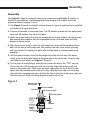
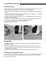
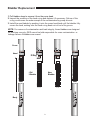
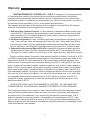
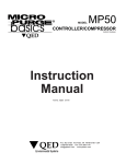
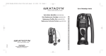
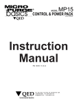
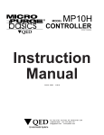
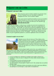
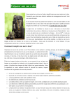
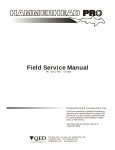
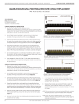
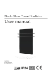
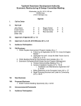
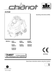
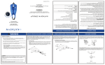
Sample Pro 3/4"
Portable
MicroPurge Pump
Sample
Portable MicroPurge Pumps
R
Instruction
Manual
Part No. 95192 3-9-04
P.O. Box 3726 Ann Arbor, MI 48106-3726 USA
1-800-624-2026 Fax (734) 995-1170
[email protected] www.qedenv.com
Contents
Page
Topic
Introduction
1
Figure 1/Pump Overview
1
D escription
2
Figure 2 / Main Components
3
A ssembly
4
Figure 3 / O-Ring Replacement
4
Attaching Tubing / Disassembly / Cleaning / Decontamination Note
5
Figure 4/ TubingAttachment Tool
5
Figure 5 / Using Needlenose Pliers for Check Ball Stop Assembly/Disassembly
6
Figure 6 / Pump Tubing Fitting Assembly
7
Figure 7 / Pump Head Assembly
8
Bladder Replacement
9
Specifications
10
QED Service Contacts
10
Important Warranty Note
10
QED W arranty
11
Contents
Introduction
Introduction
The Sample Pro 3/4” Portable MicroPurge Pump, (Figure 1) is the first pump designed specifically to meet the practical needs of sampling small diameter wells: easy
to adjust to low-flow purging rates and easy to decontaminate between sampling
points. Decon is made easier by the pump having fewer parts, disassembly without
tools, and quick-change, disposable bladders. The Portable MicroPurge Pump is compact and can pump from a 5-gallon bucket. The pump is operated by compressed gas
and a bladder pump control unit, and is ideally used with the MicroPurge basics
models MP10 and MP15 controllers. The compressed gas is on the outside of the
bladder and the pumped liquid is on the inside of the bladder, so there is no contact
between the sample and the gas.
R
Figure 1
Cover
Cover
Head
Inlet
Bladder
1-800-624-2026
www.micropurge.com
1-800-624-2026
PAT E NT P E NDING
Body
www.micropurge.com
R
ED
PAT E NT P E NDING
Body
R
ED
1
Description
Description
Figure 2 (Page 3) shows the main components of the Portable MicroPur ge Pump and
the assembled pump. The body twists of f for quick change of the disposable polyethylene (PE) bladder . The bladder simply pushes on to provide a leak-tight seal for
most applications without the use of clamps.
The cap of the pump twists off for full disassembly of the inlet and outlet check
valves and the tubing connection components.
The pump uses 1/8” O.D. tubing for compressed gas supply and 1/4” O.D. tubing for
the sample discharge. Tubing connections to the pump are made via push-in fittings
built into the top of the pump.
The push-in connections provide excellent pull out strength when used with QED
tubing, so that use of a support cable is not required. Ho wever a connection eye is
provided on the top of the pump and tubing for use of a cable when preferred. The
connection eye is threaded into the top plate of the pump and can easily be removed
or reinstalled as desired. The push-in fittings on the SamplePro pump are designed
to provide at least 25 lbs. combined pullout strength when used with QED tubing.
QED is not responsible for loss of the pump if non-QED tubing is used.
2
Description
2
14
11
5
12
13
9
7
8
1
7
6
3
6
8
4
Item No. QTY
1
1
2
1
3
1
4
1
5
1
6
3
7
2
8
2
9
1
10
1
1
11
12
1
13
1
14
1
10
3
Part No.
38437EP
38434EP
38439EP
38424
38436
38470
38471
35172
38438EP
38440EP
38435
38677
38676
38833
Description
Head
Cover
Inlet
Bladder PE
Grab Plate 1/4” Tube x 1/8” Tube
O-Ring, Viton
Ball, Teflon
O-Ring, Viton
Ball Stop
Body
Plate 1/4” Tube x 1/8” Tube
Seal Discharge
Seal Air Supply
3/4 Sample Pro Eye Bolt
Assembly
Assembly
Use Figure 2, (Page 3) to identify main pump components and Figure 3, (below) to
identify O-ring locations. Detailed exploded view drawing of the upper end of the
pump are shown on pages 7 and 8.
1. See Figure 3 (below) to identify locations where O-rings and seals are to be installed
and install all O-rings and seals.
2. Connect the bladder to the pump head. The PE bladder pushes onto the pump head
barb until the bladder fully covers the barb.
3. Attach the pump head to the body by engaging the bayonet dimples into the grooves
and twisting them together until the engagement snap is felt and head and body
alignment marks line up.
4. With the pump on its side, insert the inlet check ball (same as the discharge check
ball) into the side of the pump head, then press in the inlet valve seat by pushing
with your thumb. Pre-wetting the parts with distilled water is recommended to aid
assembly
.
5. With the pump vertical, insert the discharge check ball into the top of the pump
head, place the discharge ball stop into place above the check ball, using the supplied needle nose pliers, see Figure 5, (Page 6).
6. For the push-in tubing fittings, place the thin metal lock disk in the "TOP" up position on the top of the pump head, with the lock disk edge slots lined up with the
posts on the pump head. Then place the thick, upper plate on top of the lock disk,
again with the slots and posts lined up. Finally, twist the pump cap onto the pump
head until the engagement snap is felt and the hole in the side of the pump cap lines
with the inlet port. Cover and body alignment marks will line up.
Figure 3
Discharge Seal
1/4 Tube-38677
Ball Stop 38438EP
Ball 38471
Air Tube Seal 38676
Inlet O-Ring 38470
H ead
O-R in gs
3517 2
Blad der
O-Ring
38470
Ball
38471
Inlet
38439EP
Head 38437EP
4
Assembly/Disassembly
Attaching Tubing
A tubing insertion tool is provided to make the small-diameter tubing used on this pump
easier to grip and push into the pump. The tool is shown in Figure 4.
1. Cut both tubes to equal length; cutting the tubes at a slight
angle will make insertion
easier.
2. Grip the ¼” tube ONLY in the large groove in the insertion tool, leaving ¾-1” of tubing
extending from the end of the gripping jaw.
3. Hold the insertion tool at the jaw end of the tool, FORWARD of the tool’s pivot point,
squeezing the jaws together.
4. Push the ¼” tube into the pump while rocking the tool slightly Watch and feel for the
tube to push ¼” past the point of initial resistance into the pump.
5. Pull back on the tube to check that it is inserted firmly.
6. Repeat for the 1/8” air tube.
Figure 4
Disassembly
Use Figure 2, (Page 3) to identify main pump components and Figure 3, (Page 4) to
identify O-ring locations.
1. Reverse assembly sequence, taking care to position pump to retain check balls
during removal of valve seats and stops. A screwdriver can be used if necessary to
remove the inlet valve seat.
2. Pull the PE bladder off of the pump head barb by pulling firmly, then discard.
Cleaning / Decontamination Note
If it is desired to operate the pump outside the well, such as in a pail for decontamination
purposes, the operating pressure of the pump should be reduced to 35 PSI or less to
avoid rupturing the bladder
5
Assembly/Disassembly
Using the Supplied Needlenose Pliers for Assembly/Disassembly
Needlenose pliers are provided to make handling of certain smaller parts easier to
handle during cleaning assembly and disassembly. Figure 5 demonstrates placement
of the check ball stop into the pump head.
Figure 5
6
Figure 6
Figure 6
2
14
11
5
12
13
9
7
8
Item No. QTY Part No.
2
1 38434EP
5
1 38436
7
38471
1
8
35172
1
9
38438EP
1
11
1
38435
12
38677
1
38676
13
1
38833
14
1
Description
Cover
Grab Plate 1/4” Tube x 1/8” Tube
Ball, Teflon
O-Ring, Viton
Ball Stop
Plate
Seal Discharge
Seal Air Supply
3/4 Sample Pro Eye Bolt
7
Figure 7
Figure 7
1
7
6
3
6
Item No. QTY
1
1
1
3
2
6
1
7
Part No.
38437EP
38439EP
38470
38471
8
Description
Head
Inlet
O-Ring, Viton
Ball, Teflon
11
Bladder Replacement
1. Pull bladder down to remove it from the pump head.
2. Inspect the condition of the barb o-ring and replace it if necessary. Failure of this
o-ring could cause the water sample to be contaminated by pump drive air.
3. Install the new bladder by pushing it onto the pump head barb until the bladder fully
covers the barb, making sure the barb o-ring does not roll out of its groove.
NOTE: For reasons of contamination and leak integrity, these bladders are designed
for one-time use only. QED cannot be held responsible for cross contamination or
leakage failures if bladders are reused.
CCover
over
Head
Head
O-Ring
O-R
ing
B arb
Barb
New
New
BBladder
ladder
Old
Old
BBladder
ladder
1-800-624-2026
1-800-624-2026
www.micropurge.com
www.micropurge.com
Body
B ody
PAT E NT P E NDING
PAT E NT P E NDING
R
ED
R
ED
9
Specifications
Specifications
Materials:
Body-303 stainless steel
Inlet & Discharge Housing - 303 Stainless Steel
Bladder - Polyethylene
O-rings - Viton
Fittings:
Push-inType
Air - 1/8" (3.2 mm) O.D.
Discharge - 1/4" (6.4 mm) O.D., 3/16" (4.7 mm)I.D.
Maximum Lift: 200 Feet (61 m)
Pump Volume: .33 Ounces (10 Milliliters )
For additional assistance contact QED Service at:
Phone:1-800-624-2026 1-734-995-2547
Fax:1-734-995-1170
E-mail:[email protected]
24-Hour Service Hot Line:1-800-272-9559
IMPORTANT WARRANTY NOTE
The push-in and compression fittings and tubing on the SamplePro pump are
designed to provide at least 25 lbs. combined pullout strength when used with
QED tubing. QED is not responsible for loss of the pump if non-QED tubing is
used. Re-use of the lock plate or old tube end and/or use of other brands of
tubing may significantly reduce pull-out strength and cause loss of pump in
the well.
10
Warranty
QED ENVIRONMENTAL SYSTEMS, INC. ("Q.E.D.") warrants to the original purchaser
of its products that, subject to the limitations and conditions provided below, the products,
materials and/or workmanship shall reasonably conform to descriptions of the products and
shall be free of defects in materials and workmanship. Any failure of the products to conform to
this warranty will be remedied by Q.E.D. in the manner provided herein.
This warranty shall be limited to the duration and the conditions set forth below. All warranty
durations are calculated from the original date of purchase.
1. Dedicated-Use Systems Products- 10 year warranty on dedicated bladder pumps equipped with Q.E.D. inlet screens, and purge pumps used in periodic, non continuous ground
water sampling (up to 52 sampling events per yearAll other components, equipment and
accessories are warranted for one year.)
2. Portable-Use Systems- Pumps, Controllers and water level meters are warranted for one
year. Hose reels and Caps are warranted for ninety (90) days. Tubing and Purge Mizers
are covered by a ninety (90) day material and workmanship warrantyThere will be no warranty for application on tubing and Purge Mizers when used as part of a Portable System.
3. Separately sold parts and Spare Parts Kits- Separately sold parts and spare parts kits
. Q.E.D. are warranted for ninety
are warranted for ninety (90) days. Repairs performed by
(90) days from date of repair or for the full term of the original warranty, whichever is longer.
Buyers' exclusive remedy for breach of said warranty shall be as follows:if, and only if, Q.E.D.
.
is notified in writing within applicable warranty period of the existence of any such defect in the
said products, and Q.E.D. upon examination of any such defects, shall find the same to be
within the term of and covered by the warranty running from Q.E.D. to BuyerQ.E.D. will, at its
option, as soon as reasonably possible, replace or repair any such product, without charge to
Buyer. If Q.E.D. for any reason, cannot repair a product covered hereby within four (4) weeks
after receipt of the original Purchaser's/Buyer's notification of a warranty claim, then Q.E.D.'s
sole responsibility shall be, at its option, either to replace the defective product with a comparable new unit at no charge to the Buyer, or to refund the full purchase price. In no event shall
such allegedly defective products be returned to Q.E.D. without its consent, and Q.E.D.'s
obligations of repair, replacement or refund are conditioned upon the Buyer's return of the
defective product to Q.E.D.
IN NO EVENT SHALL Q.E.D. ENVIRONMENTAL SYSTEMS, INC. BE LIABLE FOR
CONSEQUENTIAL OR INCIDENTAL DAMAGES FOR BREACH OF SAID WARRANTY.
The foregoing warranty does not apply to major sub-assemblies and other equipment, accessories and parts manufactured by others, and such other parts, accessories, and equipment
are subject only to the warranties, if any, supplied by the respective manufacturers. Q.E.D.
makes no warranty concerning products or accessories not manufactured by Q.E.D. In the
event of failure of any such product accessory, Q.E.D. will give reasonable assistance to the
Buyer in obtaining from the respective manufacturer whatever adjustment is reasonable in light
of the manufacturer's own warranty.
11
Warranty
THE FOREGOING WARRANTY IS IN LIEU OF ALL OTHER WARRANTIES, EXPRESSED,
IMPLIED OR STATUTORY (INCLUDING BUT NOT LIMITED TO THE WARRANTIES OF
MERCHANTABILITY AND FITNESS FOR A PARTICULAR PURPOSE), WHICH OTHER
WARRANTIES ARE EXPRESSLY EXCLUDED HEREBY and of any other obligations or liabilities on the part of Q.E.D.,neither assumes nor authorizes any person to assume for it any
other obligation or liability in connection with said products, materials and/or workmanship.
It is understood and agreed that Q.E.D. shall in no event be liable for incidental or consequential damages resulting from its breach of any of the terms of this agreement, nor for special
damages, nor for improper selection of any product described or referred to for a particular
application.
This warranty will be void in the event of unauthorized disassembly of component assemblies.
Defects in any equipment that result from abuse, operation in any manner outside the recommended procedures, use and applications other than for intended use, or exposure to chemical
or physical environment beyond the designated limits of materials and construction will also
void this warranty. Q.E.D. shall be released from all obligations under all warranties if any product covered hereby is repaired or modified by persons other than Q.E.D.'s service personnel
unless such repair by others is made with the written consent of Q.E.D.
If any product covered hereby is actually defective within the terms of this warranty
Purchaser must contact Q.E.D. for determination of warranty coverage. If the return of a component is determined to be necessary, Q.E.D. will authorize the return of the component, at
owner's expense. If the productproves not to be defective within the terms of this warranty, then
all costs and expenses in connection with the processing of the Purchaser's claim and all costs
for repair, parts and labor as authorized by owner hereunder shall be borne by the purchaser.
RESPONSIBILITY OF THE PURCHASER
The original Purchaser's sole responsibility in the instance of a warranty claim shall be to notify
Q.E.D. of the defect, malfunction, or other manner in which the terms of this warranty are
believed to be violated. You may secure performance of obligations hereunder by contacting
the Customer Service Department of Q.E.D. and:
1. Identifying the product invovled (by model or serial number or other sufficent description
that will allow Q.E.D. to determine which product is defective).
2. Specifying where, when, and from whom the product was purchased.
3. Describing the nature of the defect or malfunction covered by this warranty
4. Sending the malfunctioning component, after authorization by Q.E.D. to:
QED Environmental Systems, Inc.
6155 Jackson Rd.
AnnArbor, Michigan 48103
12
P.O. Box 3726 Ann Arbor, MI 48106-3726 USA
1-800-624-2026 Fax (734) 995-1170
[email protected] www.qedenv.com