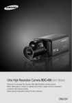
1
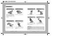
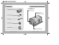
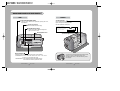
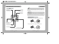
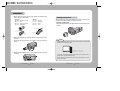
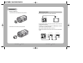
HIGH SENSITIVITY COLOR CAMERA
INSTRUCTION MANUAL
SHC-730N/P
About this manual
Before installing and using the camera, please read this manual carefully. Be sure to keep it handy for later reference.
SALES NETWORK
•
SAMSUNG TECHWIN CO., LTD.
Optics & Digital Imaging Division 145-3, Sangdaewon 1-Dong,
Jungwon-Gu, Sungnam, Kyungki-Do, Korea 462-703
TEL : 82-31-740-8137~41 FAX: 82-31-740-8145
•
SAMSUNG OPTO-ELECTRONICS AMERICA, INC. (SOA)
Closed Circuit Division 40 Seaview Drive, Secaucus N.J 07094,
U.S.A
TEL : (201) 902-0347 FAX: (201) 902-0429
•
SAMSUNG OPTO-ELECTRONICS UK LTD (SOUK)
Samsung House, 1000 Hillswood Drive Hillswood Business
Park Chertsey Surrey KT16 OPS
TEL : 44-(0)1932-45-5308 FAX: 44-(0)1932-45-5325
•
TIANJIN SAMSUNG OPTO-ELECTRONICS CO., LTD (TSOE)
7 Pingchang Rd, Nankai Dist, Tianjin, P.R China
Post Code : 300190
TEL : 86-22-2761-9698 FAX: 86-22-2761-6514
www.samsungtechwin.com
www.samsungcctv.com
P/No. : Z6806-0541-01A
VAN 04. 12
SAMSUNG CCD CAMERA
The lightning flash with an arrowhead symbol, within an equilateral triangle is
intended to alert the user to the presence of uninsulated “dangerous voltage”
within the product's enclosure that may be of sufficient magnitude to
constitute a risk of electric shock to persons.
The exclamation point within an equilateral triangle is intended to alert the user
to the presence of important operating and maintenance (servicing)
instructions in the literature accompanying the appliance.
INFORMATION - This equipment has been tested and found to comply with
limits for a Class A digital device, pursuant to part 15 of the FCC Rules.
These limits are designed to provide reasonable protection against harmful
interference when the equipment is operated in a commercial environment.
This equipment generates, uses, and can radiate radio frequency energy
and, if not installed and used in accordance with the instruction manual, may
cause harmful interference to radio communications.
Operation of this equipment in a residential area is likely to cause harmful
interference in which case the user will be required to correct the interference
at his own expense.
WARNING - Changes or modifications not expressly approved by the
manufacturer could void the user’s authority to operate the equipment.
CAUTION : To prevent electric shock and risk of fire hazards:
Do NOT use power sources other than that specified.
Do NOT expose this appliance to rain or moisture.
This installation should be made by a qualified service person and
should conform to all local codes.
Features
Warning
Fine Picture in Ultra Low
illumination.
Day & Night
SV-III built-in DSP and 1/3 high density
CCD allows bright and high quality
images to be captured in ultra low light
condition.
- 0.13Lux at Color
- 0.001Lux at Sens-Up mode
The camera provides automatic mode
change over by sensing day or night
conditions. It can change color mode in
the day condition for optimal color and
BW mode in night condition for clear
identification.
The camera needs periodic inspection.
Contact an authorized technician for inspection.
Stop using your camera when you find a malfunction.
If you use your camera around smoke or unusual heat for a long time, a
fire may be caused.
Motion Detection
Wide Dynamic Range(WDR)
SV-III DSP has Strong compensation
performance in WDR.
So It always shows obvious, clear and perfect
light contrast picture in any environment.
The camera transmits an alert signal to
the MD Output Terminal when it detects
motion of an object. If you connect an
optional alarm to the camera, you can
get the effective surveillance.
VIDEO/DC Lens Selectable
Unless the surface is suitable, it could cause falling or other hazards.
Do not hold plug with wet hands.
It could cause an electric shock.
SSNR(Samsung Super Noise
Reduction)
The camera accepts 2 types of auto iris
lenses (DC type/VIDEO type) and is set
with the VIDEO/DC selection switch.
SHC-730 has powerful DSP that can
remove image noise efficiently and it
shows clean and obvious image in low
luminance.
Do not disassemble the camera.
Miscellaneous Function
Privacy, Flip(H/V-REV), D-ZOOM, Burst
ON/OFF, SYNC(INT/LL), COLOR, TONE,
SHARPNESS.
High Resolution
Controlled by OSD menu and
RS-232C
The horizontal resolution of 520TV lines
at Color mode and 570TV lines at BW
mode can be achieved by using a high
density CCD having Double Speed
410,000 pixels SONY CCD, which provides
clean, noiseless and reliable pictures.
COLOR CCD CAMERA
Do not Install the camera on a surface that can not support it.
It may result in fire, electric shock or other hazards.
Do not use the camera close to a gas or oil leak.
It may result in fire or other hazards.
You can control the camera using OSD
menu and RS-232C jack at a remote
place.
4
User’s Manual
COLOR CCD CAMERA
5
User’s Manual
Contents
Precautions
8
Composition
10
Name and Function of Each Part
11
11
12
Front
Side
13
14
Bottom
Back
15
15
Connection
Lens
• Installing Auto Iris Lens
• Installing C/CS-Mount Lens
Connecting to Monitor
19
Connecting to Power
20
COLOR CCD CAMERA
6
User’s Manual
21
Operating Your Camera
Configuration of The Menu
21
Setting Up The Menu
• CAMERA ID
• BACKLIGHT
• WHITE BALANCE
• MOTION DETECTION
• LENS SELECTION
• SHUTTER SPEED CONTROL
• AGC
• SENSE UP
• SSNR
• SPECIAL
22
23
26
27
28
30
32
34
35
36
37
Using Reomte Jack / MD Output / D&N Input
40
Troubleshooting
42
Specifications
44
COLOR CCD CAMERA
7
User’s Manual
Precautions
Do not install the camera in
extreme temperature conditions.
Do not install or use the camera in an
environment where the humidity is high.
Only use the camera under conditions
where temperatures are between -10˚C
and +50˚C. Be especially careful to provide
ventilation when operating under high
temperatures.
It can cause the image quality to be poor.
Do not install the camera under
unstable lighting conditions.
Do not drop the camera or subject
them to physical shocks.
It can cause malfunctions to occur.
Never keep the camera face to
strong light directly.
It can damage the CCD.
Do not expose the camera to rain
or spill beverage on it.
Do not expose the camera to
radioactivity.
Do not touch the front lens of the
camera.
If it gets wet, wipe it dry immediately.
Liquids can contain minerals that corrode
the electronic components.
If it is exposed to radioactivity,
For heated CCD, it will be out of order.
Notes
Severe lighting change or flicker can
cause the camera to work improperly.
COLOR CCD CAMERA
8
It is one of the most important parts of
the camera. Be careful not to be stained
by fingerprint.
User’s Manual
• If the camera is exposed to spotlight or object reflecting strong light, smear or
blooming may occur.
• Please check that the power satisfies the normal specification before connecting
the camera.
COLOR CCD CAMERA
9
User’s Manual
Composition
Name and Function of Each Section
Front
1. High Sensitivity Color Camera
C-Mount Lens Adapter
Used to attach C-mount lens.
Tripod Mounting Bracket
Screw Hole
Used to fix the Tripod mounting
bracket on the top of the camera.
2. Auto Iris Lens Plug
3. Remote Plug
4. C-Mount Adapter
5. Instruction Manual
Back Focus Adjustment Lever
Used to adjust back focal length
COLOR CCD CAMERA
10 User’s Manual
COLOR CCD CAMERA
11 User’s Manual
Name and Function of Each Section
Bottom
Side
BACK FOCUS ADJUSTMENT LEVER
When you don’t obtain focused point after adjusting lens focus,
adjust the lever.
Auto Iris Lens Connector
Used to connect Auto Iris Lens plug.
DC/VIDEO Selection Switch
Used to choose DC or VIDEO according to the
type of your Auto Iris Lens.
Menu Setup Buttons Cover
Menu Setup Buttons
• SET Button: Used to access menu mode. Also used to confirm the setting.
• UP/DOWN Button: Used to choose the desired menu item. It also moves
the cursor up or down in the menu screen.
• LEFT/RIGHT Button: Used to change the parameter of the selected menu item.
It also moves the cursor the left or right in the menu screen.
COLOR CCD CAMERA
12 User’s Manual
Tripod Mounting Hole
Used to install the camera on an optional
tripod. The tripod must be equipped with
the screw specified as shown below.
1/4"-20 UNC (20 THREAD)
L:4.5mm±0.2mm (ISO standard),
or 0.197" (ASA standard)
L
Tripod Mounting Bracket
You can remove and install this bracket on the top of the
camera. You must use the supplied screw or the
equivalent (within 4mm). If not, the bracket may not be
fixed properly.
COLOR CCD CAMERA
13 User’s Manual
Name and Function of Each Section
Connection
LENS
Back
Video Output Jack
Used to connect an external
video monitor in jack.
Power LED
The LED turns on
when power is supplied.
The lens is not supplied with this camera. Purchase a lens suitable for your
environment. This camera accepts the auto iris lens and both C-and
CS-mount lens.
Notes
Remote Jack
Used to connect a remoteplug.
If the lens is marked with fingerprints or other marks, the image quality might be poor.
It is recommended to use a high quality lens to improve the image quality under
low illumination.
For using main functions it is recommended to use Auto Iris Lens with DC type.
Installing Auto Iris Lens
1. Peel approximately 8mm from the end of the lens cable outer cover.
approx. 8mm
D&N
Used to input Day & Night
Control Signal
2. Peel approximately 2mm from the end of the cable inner cover.
MD Output Terminal
Used to output motion detection signal.
approx. 2mm
Frame Ground
AC / DC Power Terminal
Used to connect an AC 24V or DC 12V power source.
COLOR CCD CAMERA
14 User’s Manual
COLOR CCD CAMERA
15 User’s Manual
Connection
3. Remove the cover from the iris lens plug supplied, and solder the lens
cable to the plug as shown below.
• Video type :
No. 1 Pin --- Red (Power source)
No. 2 Pin --- N.C
No. 3 Pin --- White (Video signal)
No. 4 Pin --- Black (GND)
• DC type :
No. 1 Pin --- Damping No. 2 Pin --- Damping +
No. 3 Pin --- Drive +
No. 4 Pin --- Drive -
Installing C/CS-Mount lens
Before mounting a lens, please check whether it is a C-mount or CS-mount lens.
The back focus is set for the CS-mount lens at the factory.
• Mounting a CS-Mount lens
After removing the protecting cap, attach the lens into the camera by turning
clockwise.
Lens cable
No. 3 Pin
No. 1 Pin
connector
No. 4 Pin
No. 2 Pin
4. Remove the protective cap, and attach the lens to the camera by turning
clockwise.
5. Connect the lens plug to the auto iris connector on the right side of the
camera.
6. Set the DC/VIDEO selection switch to DC or VIDEO according to the type
of the lens.
Notes
Use the lens under the specification as shown. Otherwise the lens can damage the
camera or abnormal fixing may result.
C-mount lens : 10 mm or less
CS-mount lens : 5 mm or less
A heavy lens may disturb the balance with the camera and possibly result in
damage. Don't use a lens heavier than 450g.
It is recommended to set the lens ALC mode to Av mode (Average). Pk mode can
be occurred hunting.
COLOR CCD CAMERA
16 User’s Manual
COLOR CCD CAMERA
17 User’s Manual
Connection
• Mounting a C-Mount lens
Connecting to Monitor
1. Attach the C-Mount lens adapter by turning clockwise.
Connect the VIDEO Out jack to the monitor VIDEO In jack.
Monitor
CCD Camera
• As the connecting method varies with the instruments, refer to the manual
supplied with the instrument.
2. Attach the lens to the camera by turning clockwise.
• If necessary, you can connect the monitor to the REMOTE jack on the back
of your camera. For details, see page 40.
• Only connect the cable when the power is turned off.
• Set the 75Ω/Hi-Z selection switch as shown below if you have an intermediate
device.
Intermediate
CCD Camera
COLOR CCD CAMERA
18 User’s Manual
COLOR CCD CAMERA
19 User’s Manual
End monitor
Connection
Operating Your Camera
Connecting to Power
Configuration of The Menu
Each model has different power specification. Please check the name of the
model and power specification before connecting to power source.
SETUP MENU
CAMERA ID
• OFF • ON
BACKLIGHT
• WDR • OFF
For AC / DC Power Type
• The wire is polarized. Be sure to connect the wire that white line is on covering
to ‘-’ terminal and connect the other one to ‘+’ terminal.
• Use AC 24V/500mA or DC 12V/500mA power source for SHC-730N/P
WHITE BAL.
• ATW • AWC
• MANUAL
MOTION DET.
• OFF • ON
LENS
• DC / Video • Manual
SHUTTER
• ESC • A.FLK
AGC
• OFF • LOW • MIDDLE • HIGH
Resistance of copper wire [at 20C˚ (68˚F)]
#24(0.22mm2)
#22(0.33mm2)
#20(0.52mm2)
#18(0.83mm2)
Resistance (Ω / m)
0.078
0.050
0.030
0.018
Voltage Drop (V/m)
0.028
0.018
0.011
0.006
Copper wire size (AWG)
• MANUAL
SENSE UP
• OFF • AUTO
• As the voltage drop according to the length of the cable in the above table, a
camera may malfunction if there is an excessively long cable run.
SSNR
• OFF • LOW • MIDDLE • HIGH
* Voltage for camera operation: 12V DC ±10%
* Voltage drops in the above table are variable according to types of cable manufacturer.
SPECIAL
• D-ZOOM • PRIVACY • DAY/NIGHT • SYNC
• IMAGE ADJ • PRESET • RETURN • EXIT
EXIT
COLOR CCD CAMERA
20 User’s Manual
COLOR CCD CAMERA
21 User’s Manual
Operating Your Camera
SETUP
Setting Up The Menu
Use the five Setup Menu buttons on side of the camera.
UP button
LEFT button
SET button
Select the function using
the UP or DOWN button.
CAMERA ID
BACKLIGHT
WHITE BAL.
MOTION DET.
LENS
SHUTTER
AGC
SENSE UP
SSNR
SPECIAL
EXIT
Change the status using
the LEFT or RIGHT button.
OFF
WDR
ATW
OFF
DC
ESC
MIDDLE
AUTO
MIDDLE
3. Change the status of the selected feature using the LEFT or RIGHT button.
4. When completed, move the arrow indicator to 'EXIT' and press the SET button.
DOWN button
RIGHT button
1. Press the SET button to access the setup mode.
Notes
• For the mode with you can access submenu.
• You can access submenu using SET button.
• Setup menu is displayed on the monitor screen.
Camera ID
SETUP
CAMERA ID
BACKLIGHT
WHITE BAL.
MOTION DET.
LENS
SHUTTER
AGC
SENSE UP
SSNR
SPECIAL
EXIT
OFF
WDR
ATW
OFF
DC
ESC
MIDDLE
AUTO
MIDDLE
If you enter a camera ID, the name will be displayed in the screen monitor.
1. Press the SET button to display the setup menu and move the arrow
indicator to 'Camera ID' using the UP or DOWN button.
2. Set 'Camera ID' to 'ON' using the LEFT or RIGHT button.
Notes
• If the camera ID feature is set to 'OFF',
the name will not displayed in the monitor.
2. Select the desired feature using the UP or DOWN button.
• Each time you press the UP or DOWN button, the arrow indicator moves
up or down.
• Move the arrow indicator to the desired feature item.
COLOR CCD CAMERA
22 User’s Manual
COLOR CCD CAMERA
SETUP
CAMERA ID
BACKLIGHT
WHITE BAL.
MOTION DET.
LENS
SHUTTER
AGC
SENSE UP
SSNR
SPECIAL
EXIT
23 User’s Manual
OFF
WDR
ATW
OFF
DC
ESC
MIDDLE
AUTO
MIDDLE
Operating Your Camera
3. Press SET button.
Camera ID
ABCDEFGHIJKLM
NOPQRSTUVWXYZ
abcdefghijklm
nopqrstuvwxyz
-.
123456789
CLR POS END
5. Select the position at which the camera ID will be located on the screen.
Move the cursor to 'Pos' and press SET button.
Camera ID
ABCDEFGHIJKLM
NOPQRSTUVWXYZ
abcdefghijklm
nopqrstuvwxyz
-.
123456789
CLR POS END
4. You can enter up to 15 characters.
Move the cursor to character-enter location by using the LEFT or
RIGHT button.
Select the desired character by using LEFT, RIGHT,UP or DOWN button.
The camera ID is displayed on the top-left of the monitor screen. (Default
position)
FRONT DOOR
Camera ID
ABCDEFGHIJKLM
NOPQRSTUVWXYZ
abcdefghijklm
nopqrstuvwxyz
-.
123456789
CLR POS END
to Locate, then SET
Select the position by using the 4-directional buttons, then press the SET button to
confirm the position.
Press the SET button to confirm the blinking character. The first
character is saved and the cursor in the bottom of the screen moves to
the next position.
Repeats steps and until you create the full name you want.
FRONT DOOR
Notes
• If you make a mistake while entering name
Move the cursor to ‘CLR’ and press ‘SET’ button, all characters will be removed.
If you want to correct each character, locate the cursor on the position that you
desire to erase using the arrow sign. And correct the character.
COLOR CCD CAMERA
24 User’s Manual
to Locate, then SET
6. When completed, move the cursor to 'End' and press SET button.
COLOR CCD CAMERA
25 User’s Manual
Operating Your Camera
Notes
Backlight
SV-III DSP chip built-in provides intelligent light level control to overcome
the severe Backlight conditions.
1. Press the SET button to display the setup menu and move the arrow
indicator to ‘Backlight’ using the UP or DOWN button.
SETUP
CAMERA ID
BACKLIGHT
WHITE BAL.
OFF
WDR
ATW
2. SET ‘Backlight’ to the desired mode using the LEFT or RIGHT button.
WDR: In case that bright and dark parts exist on the screen at the same time,
your camera allows you to see both parts clearly
OFF: Deactivation
• If you select manual in ‘shutter’ menu, you can’t use WDR mode.
• If you select WDR mode, the following phenomenon may appear by lighting
condition. In these cases do not select WDR mode.
Unnatural color change or unnatural phenomenon on the screen
Noise of bright part on the screen
• According to the area of bright part on the screen there may be the difference of
WDR performance so be sure to adjust the degrees of the visual angle when
installing your camera.
• If you change WDR LIMIT, unnatural phenomenon may appear.
• For the optimal WDR performance, in case of observing the object that is in the
place of the changing illumination, recommend to use Auto Iris Lens(Video or
DC type, not manual)
White Balance Control
WDR
OFF
Your camera provides 3 ‘White Bal.’ control modes. You can select the most
suitable one. You can adjust the white balance.
1. Press the SET button to display the setup menu and move the arrow
indicator to 'White Balance' using the UP or DOWN button.
2. Set ‘White Bal.’ to the desired mode using LEFT or RIGHT button.
3. Press the ‘SET’ button.
• When ‘WDR’ is chosen, you can adjust the LIMIT.
WDR SETUP
WDR LIMIT
LOW
Press SET to Return
You can select the level(LOW,MIDDLE,HIGH).
WDR sensitivity is increased or decreased.
4. When completed, press the SET button.
COLOR CCD CAMERA
26 User’s Manual
SETUP
CAMERA ID
BACKLIGHT
WHITE BAL.
MOTION DET.
LENS
OFF
WDR
ATW
OFF
DC
The four white balance control modes are as follows :
ATW(Auto Tracking White Balance): When color temperature is 1800 ~
10500K, select this mode.
COLOR CCD CAMERA
27 User’s Manual
Operating Your Camera
AWC(Auto White balance Control): The white balance is automatically adjusted
in a specific environment. In order to obtain the best result, press the SET button while
the camera focuses on white paper. If the environment including the light source is
changed, you have to adjust the white balance again.
Manual: To fine adjust, select the Manual mode. You can increase or decrease
the red or blue factor while monitoring the difference on the screen. Set to 'Manual'
mode and press the SET button. Increase or decrease the value for red(R-Gain)
and blue(B-Gain), watching the color of the picture, and press the SET button
when you obtain the best color.
2. Set ‘Motion Det.’ to the ON mode using LEFT or RIGHT button.
SETUP
CAMERA ID
BACKLIGHT
WHITE BAL.
MOTION DET.
LENS
SHUTTER
AGC
OFF
WDR
ATW
OFF
DC
ESC
MIDDLE
Press SET button.
Notes
• Proper White Balance may not be obtained under the following conditions, in these
cases select the AWC mode.
When the scene contains mostly high color temperature object, such as a blue
sky or sunset.
When the scene is dim.
If your camera faces fluorescent lamp directly or is installed in the place of the
changing illumination.
Motion Detection
Your camera transmits an alert signal when it detects motion of an object on the
screen. If you connect the camera to an external alarm, you can pay attention to
the screen when the alarm sounds. This feature is useful when you have to
monitor several screens simultaneously.
Select the two kinds of ZONE NUMBER(1 or 2), ZONE 1 covers larger
area than 2.
Turn on ZONE STATE, then MD starts to be activated.
Move the cursor to the desired menu and adjust it. You can increase or
decrease the detection area adjusting TOP, BOTTOM, LEFT, RIGHT values.
You can increase or decrease the detection sensitivity adjusting SENSITIVITY value.
1. Press the SET button to display the setup menu and move the arrow
indicator to 'Motion Det.' using the UP or DOWN button.
COLOR CCD CAMERA
28 User’s Manual
COLOR CCD CAMERA
29 User’s Manual
Operating Your Camera
· When completed, press END button.
DC / Video: When using auto iris lens
Notes
SETUP
CAMERA ID
BACKLIGHT
WHITE BAL.
MOTION DET.
LENS
SHUTTER
Tips on Using the Motion Detection Feature
• After selecting zone and sensitivity, perform a test operation to make sure it
works properly.
• If the lighting flickers, the motion detection feature might not work properly.
• The object should occupy 10% or more of its zone. The bigger the object, the
higher sensitivity.
• If the brightness of an object changes rapidly by sudden lighting change, the
camera may detect it as a motion.
• When this feature is activated, another algorithm may take more time to be operated.
• This system does not guarantee prevention of fires or thefts. The manufacturer
is not responsible for any accident or damage.
• You can use the MD output terminal jack on the rear of the camera to connect
an external alarm device. For details, see page 40.
OFF
WDR
ATW
OFF
DC
ESC
When using Auto Iris Lens with Video type
Adjust ALC volume on the lens properly. Normally ALC volume should be
turned all the way to Av(Average).
According to the type of the lens used, the lens may not perform properly.
In such a case, adjust the volume level on the lens.
For using VIDEO LENS, at first, execute IRIS ADJ(Press ‘SET’ button locating
the cursor on ‘IRIS ADJ’). If operation fails, ‘Err Can’t Close : Turn down’ or
‘Iris Test Err Flicker’ message is displayed. Then you should adjust volume
level. Until ‘Lens Level Adjustment OK’ message is displayed, adjust volume
level repeatly.
Lens Selection
You can set the type of the lens, and control the brightness of the screen.
1. Press the SET button to display the setup menu and move the arrow
indicator to 'Lens' using the UP or DOWN button.
2. Set ‘Lens’ to the desired mode using LEFT or RIGHT button.
• You can select from DC / Video, Manual
COLOR CCD CAMERA
30 User’s Manual
Notes
• When trying to execute IRIS ADJ, do it under as below conditions.
- shoot a white paper or bright wall.
- shoot light resource or bright area. (more than 150lux)
COLOR CCD CAMERA
31 User’s Manual
Operating Your Camera
• You can select speed from ‘1/60’ to ‘1/120,000’sec (NTSC Models), ‘1/50’
to ‘1/120,000’sec (PAL Models).
Manual: When using manual lens
Notes
* It is possible to adjust Sens-Up(x2 ~ x128) mode manually.
• When the auto iris lens is mounted, you have to set the DC/Video selection
switch on the side of the camera properly according to the type of the lens. The
setup window displays DC or Video according to status of this selection switch.
(refer to page 12 picture)
• When the shutter speed is increased or decreased using the LEFT or RIGHT
button, you can find the difference by monitoring the brightness of the screen.
• If you select 'DC'/'Video' mode, you can adjust the desired Brightness.
3. When completed move the arrow indicator to ‘END’ and press the SET button.
Shutter Speed Control
You can control brightness of the screen by the shutter speed.
1. Press the SET button to display the setup menu and move the arrow
indicator to ‘Shutter’ using the UP or DOWN button.
2. Set ‘Shutter’ to the desired mode using the LEFT or RIGHT button.
A.FLK(1/100 for NTSC Model,1/120 for PAL Model)
: Flickerless mode
ESC: When setting the optimal shutter speed automatically
Manual: When setting shutter speed manually
SETUP
CAMERA ID
BACKLIGHT
WHITE BAL.
MOTION DET.
LENS
SHUTTER
AGC
OFF
WDR
ATW
OFF
DC
ESC
MIDDLE
4. When completed, press the SET button.
Notes
• For effective A.FLK mode set WDR mode in Backlight menu to OFF. A.FLK mode is
not effective with WDR mode.
• If the camera directly faces strong fluorescent light with 'ESC' mode, the image
may become unstable.
• If you choose ‘ESC’, you can adjust the brightness of monitor screen using the
LEFT or RIGHT button.
• If you choose Manual mode, you can’t use WDR mode in ‘Backlight’ menu.
• If you select manual or A.FLK mode, Sense up is not operated.
3. If you choose ‘Manual’, select the optimal shutter speed.
COLOR CCD CAMERA
32 User’s Manual
COLOR CCD CAMERA
33 User’s Manual
Operating Your Camera
AGC (Auto Gain Control)
Sense up
To get brighter picture.
1. Press the SET button to display the setup menu and move the arrow
indicator to ‘GAIN’ using the UP or DOWN button.
2. Set ‘gain’ to desired mode using the LEFT or RIGHT mode.
HIGH: Gain is increased or decreased from 0 to 34dB automatically as
following the illumination.
MIDDLE: Gain is increased or decreased from 0 to 27dB automatically as
following the illumination.
You can always get the clear image with this function under night or lowlighting level.
1. Press the SET button to display the setup menu and move the arrow
indicator to 'Sense up' using the UP or DOWN button.
2. Set ‘Sense up’ to the desired mode using the LEFT or RIGHT button.
Auto: When your camera is under night or low-lighting level, select this mode.
OFF: Deactivation
SETUP
LOW: Gain is increased or decreased From 0 to 24dB automatically as
following the illumination.
CAMERA ID
BACKLIGHT
WHITE BAL.
MOTION DET.
LENS
SHUTTER
AGC
SENSE UP
SSNR
SPECIAL
EXIT
OFF: Deactivation
SETUP
CAMERA ID
BACKLIGHT
WHITE BAL.
MOTION DET.
LENS
SHUTTER
AGC
SENSE UP
SSNR
SPECIAL
EXIT
COLOR CCD CAMERA
OFF
WDR
ATW
OFF
DC
ESC
MIDDLE
AUTO
MIDDLE
34 User’s Manual
OFF
WDR
ATW
OFF
DC
ESC
MIDDLE
AUTO
MIDDLE
Notes
• If you press the set button on ‘Auto’ mode. You can adjust brightness by increasing or
decreasing the shutter speed. (EX. x2,...., x32, x64, ...., x128)
• If you increase the number of shutter speed, moving object gets an more afterimage.
• Under Sense up activated noise, sports or a whitish phenomenon may appear in the
picture as the sensitivity of the camera is increased. This is normal phenomenon.
COLOR CCD CAMERA
35 User’s Manual
Operating Your Camera
SSNR(Samsung Super Noise Reduction)
SPECIAL
To reduce the noise on the screen.
1. Press the SET button to display the setup menu and move the arrow indicator
to ‘SSNR’ using the UP or DOWN button.
2. Set ‘SSNR’ to desired mode using the LEFT or RIGHT mode.
LOW: low reduction of the noise
MIDDLE: middle reduction of the noise
HIGH: high reduction of the noise
OFF: Deactivation
SETUP
CAMERA ID
BACKLIGHT
WHITE BAL.
MOTION DET.
LENS
SHUTTER
AGC
SENSE UP
SSNR
SPECIAL
EXIT
OFF
WDR
ATW
OFF
DC
ESC
MIDDLE
AUTO
MIDDLE
Notes
• If you change the ‘AGC’ menu from LOW to HIGH, sensitivity is increased as well
as noise on the screen.
• If AGC is OFF, you can’t select LOW/MIDDLE/HIGH on SSNR menu.
COLOR CCD CAMERA
36 User’s Manual
1. Press the SET button to display the setup menu and move the arrow indicator
to ‘SPECIAL’ using the UP or DOWN button.
2. Press the SET button.
D-ZOOM: You can select an electronic zoom mode among x2, x4,x8
mode.
- After selecting zoom mode you want, adjust PAN and TILT value by
pushing the left or right key to locate the position that you want to see.
COLOR CCD CAMERA
37 User’s Manual
Operating Your Camera
PRIVACY: To mask area which you want to mask
- OFF: Deactivation
- ON: Privacy mode activated
· Press the SET button.
· 4 AREAS are selectable. Select the area you want(AREA1, AREA2, AREA3,
AREA4)
· Set AREA STATE ‘ON’ using LEFT or RIGHT button.
· Make the size of PRIVACY AREA by changing TOP, DOWN, LEFT, RIGHT
values.
DAY/NIGHT: choose color or B/W mode.
- COLOR : color mode
- B/W : B/W mode
- EXT : It enables user to control DAY/NIGHT mode by Inputing external
signal.
- AUTO : Under general condition, D/N filter is fixed at DAY mode, but under
low luminance condition, it change into NIGHT mode
automatically. The case of the opposition is also same.
Notes
• When you use Auto Iris Lens with Video type, do not set the level on the lens to too
low, Color/BW may not change over automatically.
• When Gain in SET UP menu is OFF, Color / BW do not change over automatically.
• If AGC is OFF, you can’t select AUTO mode on DAY/NIGHT menu.
• For the stable operation, whenever the mode is changed over between color and BW
mode, five setup menu buttons on the camera do not operate for about 3 seconds.
• It is possible to turn on or off the burst signal on B/W mode.
• The object may be more out of focus when using a source of near-infrared light
than using the visible light.
SYNC : Two SYNCHRONIZATION modes are available INTERNAL and
EXTERNAL LINE-LOCK. In LINE-LOCK mode, it synchronizes the
video signal between cameras without a synchronous generator. The
line-lock synchronization is only used in the areas of 60Hz (NTSC
Models) / 50Hz (PAL Models).
- INT : Internal synchronization - LL : External line-lock synchronization
· If you choose ‘LL’, you can adjust the desired phase. Press the SET button.
-You can adjust the desired phase from 0 to 359.
Notes
• When the power frequency is 50Hz, you can not use line-lock mode(NTSC Models).
• When the power frequency is 60Hz, you can not use the line-lock mode(PAL Models).
• ‘Sync.’ mode is fixed to ‘INT’ in DC 12V input power.
COLOR CCD CAMERA
38 User’s Manual
COLOR CCD CAMERA
39 User’s Manual
Operating Your Camera
IMAGE ADJ: This includes the factors related to the image quality or special
function.
- H-REV : Set ‘ON’, then each side of image(left and right) is exchanged on
vertical axis.
- V-REV : Set ‘ON’, then image changes upside down.
- TONE : As you increase the value using left or right button the whole level
would be brighter.
- SHARPNESS : As the value goes high, edge of image become strong and
obvious. But if increasing the value too much, some noise
may appears on image and image may looks unnatural.
- COLOR : As you increase or decrease the value, image chroma level
increases or decreases but the burst level doesn’t.
PRESET: To reset your camera to factory default condition
RETURN: To move Top-menu
EXIT: To finish setting menu
1. RS-232C Communication Setting.
• Mode : Serial • Data Bit : 8
• Port : Com1
• Parity : None
2. Setup menu Command.
Setup menu
Set
Up
Down
Right
Left
Command
153
65
66
67
68
+4.0V~+5.0V
There is motion
• the reflected letters on mirror will be seen when activating H-REV or V-REV.
Using Remote Jack / MD Output / D&N Input
If you connect a remote plug to the REMOTE jack on the rear of the camera
as shown below, you can access the menu setup mode from a remote place.
Byte
1
1
1
1
1
3. MD(Motion Detection) output Signal Level(less than 10mA)
0V
There is no motion
Notes
• Bit/sec : 9600bps • Stop Bit : 2
• Flow Control : XON/XOFF
5±0.5sec
4. D&N input Control Signal
If you want to use EXT mode, consist proper system that satisfy below
condition
• For DAY mode, D&N terminal should be open from external signal
• For B/W mode, D&N terminal should be short to ground.
Notes
• You must turn the camera power off when you connect or remove the remote plug.
COLOR CCD CAMERA
40 User’s Manual
COLOR CCD CAMERA
41 User’s Manual
Troubleshooting
If you have trouble operating your camera, refer to the following table. If the
guidelines do not enable you to solve the problem, contact an authorized
technician.
Problem
Solution
Problem
Motion Detection
function is not active.
• Have you set ‘Motion Det.’ menu to OFF?
• Have you set ‘SENSITIVITY’ to too low?
• Have you set ‘MD Area’ properly?
The color of the picture
is not matched.
• Check that you have properly set the ‘White Bal.’
menu.
The image on the screen
flickers.
• Is the camera facing to direct sunlight or fluoresent
lighting? Change the camera position.
• Are you using Auto Iris Lens? Check that you have
properly connected the lens plug to the Auto Iris
connector on the side of the camera.
L/L mode isn’t able to
be selected.
• Have you connected your camera to DC power
source? Connect it to AC power source.
L/L is not operating
properly.
• Check the frequency of power supply.
(60Hz for NTSC, 50Hz for PAL)
Solution
Nothing appears on
the screen.
• Check that the power cord and line connection
between the camera and monitor are fixed properly.
• Check that you have properly connected VIDEO
cable to the camera VIDEO output jack.
• Check that the DC/VIDEO selection switch on the
side of the camera is set to a proper position
according to the type of your auto iris lens.
• Are you using Auto Iris Lens with VIDEO type?
Adjust VR Level properly (refer to page 31)
The image on the
screen is dim.
• Is lens stained with dirt? Clean your lens with soft,
clean cloth.
• Set the monitor to proper condition.
• If the camera is exposed to too strong light, change
the camera position.
• Adjust the lens’ focus properly.
The image on the
screen is dark.
• Adjust the contrast feature of the monitor.
• If you have an intermediate device, set the 75Ω / Hi-z
properly. (refer to page 19)
• Are you using the Auto Iris Lens? Adjust the level
on the lens properly.
The camera is not working
properly, and the surface
of the camera is hot.
• Check that you have properly connected the camera
to an appropriate power source. (refer to page 20)
COLOR CCD CAMERA
42 User’s Manual
COLOR CCD CAMERA
43 User’s Manual
DECLARATION OF CONFORMITY
Specifications
NTSC (SHC-730N)
AC24/DC12(±10%), 4.5W
POWER
C
C
D
S
y
n
c.
PAL (SHC-730P)
Total Pixels
811(H) x 508(V)
795(H) x 596(V)
Effective Pixels
768(H) x 494(V)
752(H) x 582(V)
89 / 336 / EEC
Manufacturer's Name
SAMSUNG TECHWIN CO., LTD
Manufacturer's Address
Scanning System
2:1 Interlace
Synchronization
Internal/Line Lock
Frequency
Horizontal:15.734KHz, Vertical :59.94Hz
Resolution
520TV Lines(Min.);Color, 570TV Lines(Min.);B/W 520TV Lines(Min.);Color, 570TV Lines(Min.);B/W
Horizontal: 15.625KHz, Vertical : 50.00Hz
Video Output
1.0Vp-p/75Ω(Video 0.714Vp-p, Sync 0.286Vp-p)
1.0Vp-p/75Ω(Video 0.7Vp-p, Sync 0.3Vp-p)
52dB (AGC Off,Weight ON)
Min. Illumination
0.13Lux/F1.2 at Color(50IRE), 0.01Lux/F1.2 at BW(50IRE)
WDR
52dB
COLOR / BW/AUTO (Filter Auto Change) / EXT
Day & Night
(External Day/Night mode control capability via terminal at the back panel)
Gain Control
Low,Middle,High,OFF Selectable
White Balance
KYUNGNAM, KOREA, 641-120
European Representative Name
European Representative Address
Equipment Type/Environment
AUTO/MANUAL (1/60 ~ 1/120,000sec)
Sens-Up
SHC-730P
Beginning Serial NO.
S4120001
Year of Manufacture
2004. 12. 01
Conformance to
EN 50081-1 : 1992
EMC-Directive 89/336 EEC and 92/31/EEC
AUTO/MANUAL (1/50 ~ 1/120,000sec)
EN 50130-4 : 1996
ON/OFF (selectable limit~X128)
O.S.D
CCTV Camera
Model Name
ATW/AWC/Manual (1800˚K ~10,500˚K)
Electronic shutter speed
SAMSUNG TECHWIN CO., LTD
42, SUNGJU-DONG CHANGWON-CITY,
1/3 inch, Vertical double density interline CCD
Size
S/N (Y signal)
E
L
E
C
T
R
I
C
A
L
Application of Council Directive(s)
Built-in
Motion Detection
ON/OFF (Built-in Alarm output connector)
RS-232C
Built-in
SSNR
Low, Middle, High, OFF Selectable
FLIP
Built-in (Up/Down, Left/Right)
D. ZOOM
We, the undersigned, hereby declare that the equipment specified above conforms
to the above Directive(s).
Built-in (~x8, Pan Tilt)
Privacy Function
ON/OFF (4 Programmable Zone)
IRIS Control
DC / Video
CS Mount (Easy Focus type)
Lens Mount
(C-Mount is mountable by using adaptor)
Dimension
70(W) X 56(H) X 130(D)mm
Operating temperature
-10˚C ~ +50˚C [14˚F ~ 122˚F]
Operating Humidity
Legal Representative in Europe
Full Name
YOUNG TAEK SON
Full Name
Signature
Signature
Position
QUALITY CONTROL MANAGER
Position
Max 90% RH
Place
CHANGWON, KOREA
Place
480g
Date
2004. 12. 01
Date
Weight
COLOR CCD CAMERA
SAMSUNG TECHWIN CO., LTD
Manufacturer
44 User’s Manual
MEMO
MEMO