1
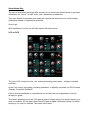
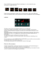
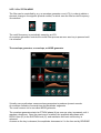
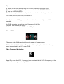
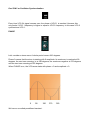
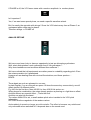
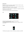
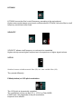
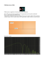
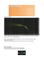
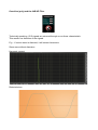
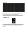
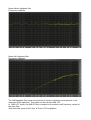
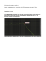
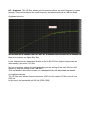
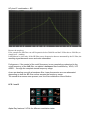
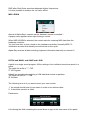
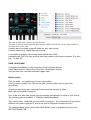
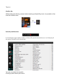
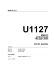
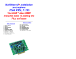
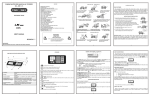
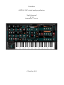
TubeOhm
ALPHA- RAY virtual analog synthesizer
English manual
V 1.0
Translation : Xavier
© TubeOhm 2012
About Alpha-Ray:
The idea of Alpha-Ray emerged after several of our users have asked where to get basic
information on „virtual“ as well as on „real“ (hardware) synthesizers.
This user manual is therefore also meant as a tutorial on the basics of a virtual analog
synthesizer based on subtractive synthesis.
So let’s go ..
With clarification in mind, we will first explain the basic terms.
VCO or DCO
The term VCO comes from the „old“ analog technology and means „voltage controlled
oscillator“.
In the 21st century everything, including oscillators, is digitally controlled, so DCO means
„Digitally Controlled Oscillator“
One or several oscillators in a synthesizer are actually the sound generators, like the
strings of a guitar.
Thus when pressing a key, the VCO gets a control voltage telling it at which frequency (or
note) to oscillate. On the other hand, the DCO gets a digital information telling it at which
frequency (or note) to oscillate. The result is the same.
Each VCO/DCO can generate different waveshapes, ie. sinus, sawtooth, ramp,
squarewave, triangle and noise.
Each of these waveshapes contains more or less harmonics, and sounds differently.
A VCF can influence more or less the harmonic content and shape the sound accordingly.
VCF/DCF
The filter is one of the most important component of a synthesizer.
VCF means „voltage controlled filter“, DCF is therefore a „digitally controlled filter“ .
Whether voltage controlled or digitally controlled, the control refers to the filter’s cutoff
frequency.
The cutoff frequency is the frequency at which a filter begins to attenuate. We’re talking
here about a LP filter, ie. a lowpass filter, meaning that the higher frequencies are
attenuated.
The specification given in dB refers to the slope of the filter.
The slope is a measure of the filter’s attenuation when frequency is doubling, ie per
octave.
We are dealing here with SUBSTRACTIVE SYNTHESIS, since the filter can be controlled
to attenuate more or less certain frequencies.
The filter attenuates part of the total harmonic content of the signal.
Filter Q or filter resonance
If a filter is looped back, meaning its resonance is increased, it will eventually begin to
oscillate, and then as such it can be used as a sound generator.
The filter’s tone becomes harsher when its gain at cutoff frequency is increased. As soon
as Q=1 is reached, the filter begins to self-oscillate.
VCF / VCA / PITCH ADSR
The filter can be controlled by e.g. an envelope generator or an LFO, in order to obtain a
dynamic change in the signal’s spectral content, in which case the filter’s cutoff frequency
is controlled.
The cutoff frequency is periodically swept by an LFO.
An envelope generator controls the overall filter process as soon as a key is pressed until
it is released.
The envelope generator, or envelope, or ADSR generator
Virtually every synthesizer uses envelope generators to produce dynamic sounds.
An envelope consists of several time and amplitude -segments.
The most common ist he so-called ADSR generator.
The envelope generator starts its ATTACK phase (A) as soon as a key is pressed, until it
reaches a maximum. Once the maximum is reached, the amplitude decreases with
DECAY time (D) to the SUSTAIN level (S), and maintains this level until the key is
released.
As soon as the key is released, the amplitude decreases to 0 in the time set by RELEASE
(R).
'A' stands for the time required to go fro 0 to the envelope’s maximum level.
'D' is the time required to go from the maximum level to the SUSTAIN LEVEL.
'S' sets the SUSTAIN LEVEL
'R' is the time required by the envelope to decrease to 0 when the key is released.
>>ATTACK, DECAY, SUSTAIN, RELEASE<<
A synthesizer uses ADSR generators for several tasks, and usually several of them are
available.
An ADSR generator controls the cutoff frequency of the filter
A second one controls the volume
Another one can control the PWM or the VCO pitch.
PW and PWM
PW means Pulse Width, and sets the pulse shape of a square wave.
PWM is Pulse Width Modulation. The pulse width, or pulse phase behavior of a square
wave, is modulated by an LFO or an ADSR.
FM or Frequency Modulation
Alpha-Ray allows the VCO 1 frequency to be modulated by the VCO 2 frequency, so that
new harmonics are generated by VCO 1.
Osc SYNC or Oscillator Synchronization.
Every time VCO 2’s signal crosses zero, the phase of VCO 1 is resetted. However this
only works if VCO 1 frequency is higher or equal to VCO 2 frequency. In this case VCO 2
synchronizes VCO 1.
PHASE
Let’s consider a sinus wave. A whole period covers 360 degrees.
Phase 0 means that the sinus is starting with 0 amplitude. Its maximum is reached at 90
degrees, the next zero crossing is at 180 degrees, the maximum negative at 270 degrees
and the next zero crossing at 360 degrees.
When PHASE is on, the VCO wave starts with phase = 0 and amplitude = 0.
We have a so-called predefined transient.
If PHASE is off, the VCO wave starts with a random amplitude i.e. random phase.
Is it important ?
Yes, if we want some punchy bass, we need a specific waveform attack.
But it’s exactly the opposite with strings ! Since the VCO starts every time at Phase 0, an
unpleasant spike noise may be heard.
Therefore strings >> PHASE off
ANALOG DETUNE
We have once been lucky to have an opportunity to test an old analog synthesizer.
Well, what distinguishes a real synthesizer from a VA synthesizer ?
Why does hardware sound somehow different than software ?
We have noticed that old equipments are rather prone to unstability regarding pitch. Even
the octave precision isn’t guaranteed.
However we are dealing here with minimal flucutuations, and these produce …
BEATS.
These beats as such are pleasant to our ears.
In plain English: if on an old synth we press 10 times the same key consecutively, we will
obtain indeed 10 different pitchs.
E.g. 440 Hz the first time, then 440.02 Hz, then 439.99 Hz and so on..
When played in combination, the notes already produce a phasing or a light chorus effect.
And this without any special effect.. „That’s the trick“
And this can also be simulated..
Thus when ANALOG is set, a small random pitch value is added to the VCO pitch
information.
DETUNE sets the magnitude of the random values.
And suddenly it sounds no longer so cold or sterile. The effect is however very subtle and
only noticeable when switched off. It depends also on the sound used.
MODULATION
Modulation is the influence of frequency, amplitude or harmonic content of a sound
generator buy another component such an LFO
We talk about VIBRATO when the frequency of an oscillator is modulated, and about
TREMOLO when its amplitue ie. its volume is modulated.
Depending on the oscillator waveform, e.g. a squarewave, it is possible to dynamically
modulate the pulse width by a LFO.
In which case we talk about PWM or Pulse Width Modulation.
LFO
An LFO is a low frequency oscillator, ie. a slow beating oscillator.
Its frequency range is typically 0.01... 40 Hz.
An LFO is used typically to modulate components such as VCO/DCO, VCF/DCF
and VCA/DCA
F-ADSR
F-ADSR sets the magnitude of the filter cutoff frequency modulation by the ADSR.
K-TRACK
K-TRACK moves the filter’s cutoff frequency according to the note played.
Higher notes would always sound more muffled without K-TRACK, since the filter’s cutoff
frequency would have been fixed.
VELOCITY
VELOCITY allows cutoff frequency or volume to be controlled.
Higher velocity means higher frequencies in the spectrum or higher signal volume.
VCF I/II
Switches between a ladder-network filter (LP) or a state variable filter (LP).
They sound differently.
P-Mod (ulation) or VCO pitch modulation
The VCO pitch is dynamically controlled.
The modulation source can be LFO 1, LFO 2 or Pitch ADSR.
P-MOD sets the magnitude of the pith modulation.
Keyword: siren effects !
PWM Modulation (PWM)
PWM sets the magnitude oft he the pulse width modulation !
All 3 VCOs can generate a squarewave. The squarewave can be pulse-modulated.
First in a static way by the PWM control.
Technically it changes the harmonic content of the sound. A pulse width of 50% produces
a rather „bassy“ sound. A pulse width of 90% generates a nasal, medium-coloured sound.
Harmonic content
Harmonic content
Thanks to PWM (Pulse Width Modulation), it is possible to dynamically control the pulse width
ratio with LFO 1, LFO 2 or pitch envelope.
LFO 1 / 2 periodically change the harmonic content of the signal according to their
respective frequencies.
The pitch envelope changes the harmonic content of the VCOs accordingly..
PW= Pulse Width
Sets a predefined pulse width ratio of a squarewave.
This pulse width ratio can be modulated with PWM
Overdrive (poly) and the 6dB HP Filter
Technically speaking, VCO signals are mirrored through a non-linear characteristic.
This results is a distortion of the signals
E.g. : if a sinus wave is distorted, it will contain harmonics
Sinus wave without distorsion
Harmonic content
Distorted sinus
Harmonic content
The signal includes more or less harmonics according to the level of distorsion.
A sawtooth is perceived more clearly with some added harmonics.
The optimal DRIVE setting is 30..70 %. Too much DRIVE can significantly distort the
signal which then can be perceived as „unpleasant“ distorsion. In contrast to a light
„crunchy“ distortion which slightly roughen the sound.
The 6dB highpass filter
attenuates low frequencies and is clearly a benefit to the sound. Extreme settings remove
the complete lower spectrum, and the instrument gains a strong medium tone colour.
While working with Alpha-Ray’s main filter, we noticed that lower frequencies remain
stable in amplitude. Setting the cutoff frequency only affects more or less higher
frequencies.
Noise without highpass filter
Frequency response
Noise with highpass filter
Frequency response
The 6dB highpass filter has a second mode in order to introduce more dynamic in the
lower part of the spectrum. This mode can be set with LINK VCF.
In ’LINK-VCF' mode, the 6dB HP filter is coupled to the actual cutoff frequency control of
the main filter.
With actual we mean cutoff, Velo, K-Track, LFO modulation.
What does this coupling excatly do ?
A smal consideration here..Actually the 6dB HP filter is before the main LP filter .
Explanation of terms:
(LP = lowpass filter. A lowpass filter allows all frequencies below the cutoff frequency to
pass through. Frequencies above the cutoff frequency are attenuated with a 12..24
dB/octave (frequency doubling) slope.
HP = highpass. This HP filter allows only frequencies above the cutoff frequency to pass
through. Frequencies below the cutoff frequency are attenuated with a 6 dB/oct slope.
Highpass behavior
Now let’s consider our Alpha-Ray filter.
Lower frequencies are attenuated thanks to the 6 dB HP filter. Higher frequencies are
attenuated by the main (LP) filter.
We get a narrower frequency band depending on the setting of the main filter’s cutoff
frequency and the setting of the 6 dB filter !
This combination allows the creation of a bandpass filter with adjustable bandwidth.
A simplified example:
The HP filter only allows frequencies above 1000 Hz, the master LP filter cuts off over
5000 Hz.
In this case, the bandwidth is 4000 Hz (5000-1000).
HP plus LP combination = BP
Beware the trap here:
If for example the HP filter cuts off frequencies below 5000 Hz and the LP filter above 5000 Hz,we
simply hear .. nothing.
It should now be clear why. If the HP filter passes frequencies that are attenuated by the LP filter, the
resulting signal becomes more and more attenuated.
Furthermore, if the control of the cutoff frequency is now completly synchonized to the
cutoff frequency of the 6dB filter, we obtain a bandpass filter controlled by VELO, VCF
ADSR … through the complete sound frequency range.
As we are dealing now with a bandpass filter, lower frequencies are now attenuated
depending on how the BP filter moves accross the frequency range.
The sound thus seems more present, and the filter modulation more effective.
LFO 1 and 2
Alpha-Ray features 2 LFOs for different modulation tasks.
LFO 1 and 2 feature 11 different waveforms.
Thanks to the SYNC button, both can be synchronized to the keyboard to start with an
initial 0 Phase.
Each time a key is pressed, the LFOs begin to oscillate starting withe phase = 0.
If the BPM button is set, then the frequencies of the LFOs are synchronized to the VST
Host program.
E.g. if set to 120 BPM, the frequencies of the LFOs can be adjusted to 1/16,1/8,1/4,1/2,
1,2,4 of the host clock frequency.
The M-LFO2 control allows the modulation of LFO 1 frequency by LFO 2.
LFO 2 controls the frequency of LFO 1 in this case.
LFO 2’s Random function generates a random value evolving according to the frequency
set.
This random value can be routed to all destination modules.
WAVE sets the desired waveform.
PITCH and MODULATIONS joystick
There are more control and modulation functions with a modulation-joystick in order to
modulate and play the instrument in real time with added flexibility.
The X direction controls the pitch, ie. the frequencies of the VCOs.
The Y direction controls the modulation.
Pitch modulation includes its own LFO which frequency is set by FRQ.
The magnitude of the pitch modulation of the LFO is controlled by the Y direction and by
M-W. M-W sets the maximum modulation that can be reached at Y end stop.
FIX sets the magnitude of the basic modulation.
The modulation of the VCOs by the LFOs can also by set by AFTER TOUCH.
P-W means Pitch-Wheel and sets in X direction the maximum number of semitones transposed by
the VCOs when moving the joystick.
The VCF control sets the cutoff frequency by AFTERTOUCH.
When MF is set, the cutoff frequency is modulated by the LFO and AFTERTOUCH..
Portamento has 2 functions as well.
When Portamento is set, the pitch glides to the next key pressed.
The 2nd mode is called AUTO-PORTA, and is operating only when Alpha-Ray is set to
mono
AUTO PORTA is set by the switch just left to the Porta control.
In AUTO-PORTAMENTO mode, each individual note is generated without portamento.
When a further note is played while the current is still active (key still pressed), the
portamento kicks in and the pitch then glides from note 1 to note 2.
The MONO-POLY switch sets Alpha-Ray in 10 voices mode or in monophonic (1 voice)
mode.
The effect section
The effect section includes 4 different effects which are connected in serie at the output of
the synthesizer.
OVERDRIVE>> CHORUS>>DELAY>>REVERB
The overall signal first passes through a 2-stage, monophonic overdrive.
Its effect is similar to a guitar distorsion box. Drive 1 generates moderate distorsion, Drive
2 harder distorsion. MIX sets the distorsion factor.
The 3-stage chorus „phattens“ the sound. Chorus is set to the 3rd mode when both
buttons CHORUS 1 and CHORUS 2 are ON..
FREQ controls chorus modulation, and MIX mixes original and chorused signals.
Delay can operate either in R-L mode (stereo delay) or in normal mode.
Delay times are set to the host sync clock with BPM-SYNC.
DELAY an FEEDBACK set the delay time and feedback.
MIX mixes original and delayed signals.
The final sound is polished by a REVERB.
In order to extend the sound capabilities, it is possible to use the reverb as a kind of echo,
where individual reflections can be clearly distinguished. This depends on the settings.
SIZE sets the Predelay, the reverbed signal being actually delayed. This is called
PREDELAY.
ROOM changes the room size, DECAY the overall time for the reverbed signal to fade
away.
FEEDBACK and DIFFUSION affect reverb density.
PRE_DMP and DMP are 2 lowpass filters. PRE_DMP is located before the actual reverb,
DMP after. Both filetrs somehow attenuate higher frequencies.
It is thus possible to achieve the «oil tank» effect.
MIDI LEARN
Almost all Alpha-Ray’s controls can be hardware remote-controlled !
A popup menu appears when right-clicking a control.
When MIDI-LEARN is selected, the control waits for incoming MIDI data from the
hardware controller.
You just have then to turn a knob on the hardware controller. Normally MIDI CC
information are sent that actually move the knob on the synth.
Alpha-Ray receives all data including keyboard information basically on channel 1!
PATCH and BANK, and SAVE and LOAD
A patch is a single sound program. All the settings of an individual sound are saved in a
patch.
The patch file suffix is ***. FXP
'P' for Program
A bank is a soundbank consisting of 128 individual sounds or patches.
The bank file suffix is ***.FXB
'B' for Bank
The following is to do if you want to save your own sounds:
1: the sound should have its own name in order to be retrieved later.
2: it should be saved in a folder
Patchname :
Left-clicking the field containing the name allows to type in the new name of the patch.
The name should always first be typed in the field.
The name is directly transfered to the data browser with SAVE PATCH, and it is then possible to
save the pactch in one click.
It makes sense to create a specific folder for your own sounds.
It can be named e.g. 'Alpha-Ray own sounds'
It is possible to retrieve a prevouisly saved sound with LOAD.
It possible with COPY to copy a sound from one position in the bank to another. E.g. from
pos. 1 to pos. 35.
SAVE LOAD BANK
A complete soundbank is a file consisting of 128 individual sounds.
A new bank loaded in Alpha-Ray, offers new 128 available sounds.
You can save your own bank and load it again later.
Bank creation.
First you need …soundpatches. As many as possible !
Once you have created your 128 own sounds, you can collect them in your own
soundbank.
All patches have their own, meaningful names and are saved in a folder.
Now a bit of handwork is required.
First, to be on a safe side, please copy the existing soundbank in a folder of your choice.
The following path is available: c:\TubeOhm\Alpha-Ray\Bank\
Then select patch 1 and load your own patch in position 1, then select patch 2 and load a
different own patch in position 2, and so on until all 128 patch locations are full !
The complete bank is then saved with SAVE BANK, under a dedicated name such as :
MY-FIRST BANK.FXB
That’s it..
Another tip:
While holding the Ctrl key pressed when tweaking an Alpha-Ray knob, it is possible to fine
tune the selected knob.
Internal patchbrowser
Left-clicking the upper display window (red dot) will open the internal browser. It will display all
the patches included in the current bank.
You can now easily find a patch.
Clicking a patch directly will load it.
That’s all, enjoy Alpha-Ray !
Final word:
Only Alpha-Ray, the synthesizer itself, is freeware. You can use the sounds without
restriction.
However, the cost to unlock the effects section is 4.95€.
We think it’s a very fair price for a fine instrument.
Hey, we live from the sale of our instruments and it's not that easy…
4.95€ is your support so that we can continue our work, and we consider it as a „Thank
you“
With this mind, we wish you much fun with this instrument !
TubeOhm
09.01.2012