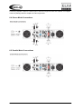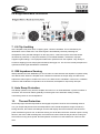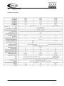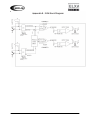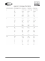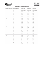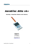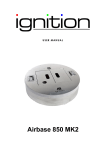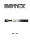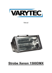
1
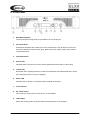
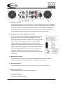
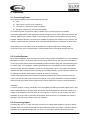
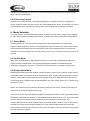
User manual
Table of content
1.
Safety instructions ........................................................................................................................... 3
1.1.
2.
FOR SAFE AND EFFICIENT OPERATION ............................................................................ 3
Front View........................................................................................................................................ 4
2.1.
3.
Rear & Side Views ................................................................................................................... 4
Introduction ...................................................................................................................................... 5
3.1.
Unpacking ................................................................................................................................ 5
3.2.
Installation and Mounting ......................................................................................................... 5
4.
Front Panel ...................................................................................................................................... 6
4.1.
5.
Rear Side ................................................................................................................................. 7
Operation ......................................................................................................................................... 8
5.1.
Connecting Power ................................................................................................................... 8
5.2.
Cooling System ....................................................................................................................... 8
5.3.
Connecting Inputs .................................................................................................................... 8
5.4.
Connecting Outputs ................................................................................................................. 9
6.
Mode Selection ................................................................................................................................ 9
6.1.
Stereo Mode ............................................................................................................................ 9
6.2.
Parallel Mode ........................................................................................................................... 9
6.3.
Bridged Mono Mode ................................................................................................................ 9
6.4.
Stereo Mode Connections ..................................................................................................... 10
6.5.
Parallel Mode Connections .................................................................................................... 10
6.6.
Bridged Mono Mode Connections ......................................................................................... 11
7.
LX Clip Limitting ............................................................................................................................. 11
8.
IGM Impedance Sensing ............................................................................................................... 11
9.
Auto Ramp Protection ................................................................................................................... 11
10.
Thermal Protection .................................................................................................................... 11
11.
LRS Short Circuit Protection...................................................................................................... 12
12.
DC Voltage Protection ............................................................................................................... 12
13.
Subsonic Frequencies ............................................................................................................... 12
14.
Appendices ................................................................................................................................ 13
2 / 17
1. Safety instructions
This device is suitable for indoor use only.
All modifications to the device will void the warranty.
Repairs are to carry out by skilled personnel only.
Use only fuses of the same type and original parts as spare parts.
Protect the unit from rain and humidity to avoid fire and electric shocks.
Make sure to unplug the power supply before opening the housing.
1.1. FOR SAFE AND EFFICIENT OPERATION
Be careful with heat and extreme temperature
Avoid exposing it to direct rays of the sun or near a heating appliance.
Not put it in a temperature bellow 23°F /-5°C, or exceeding 95°F /35°C.
Keep away from humidity, water and dust
Do not place the set in a location with high humidity or lots of dust.
Containers with water should not be placed on the set.
Keep away from sources of hum and noise
Such as transformer motor, tuner, TV set and amplifier.
To avoid placing on un-stable location
Select a level and stable location to avoid vibration.
Do not use chemicals or volatile liquids for cleaning
Use a clean dry cloth to wipe off the dust, or a wet soft cloth for stubborn dirt.
If out of work, contact sales agency immediately
Any troubles arose, remove the power plug soon, and contact with an engineer for repairing,
do not open the cabinet by yourself, it might result a danger of electric shock.
Take care with the power cable
Never pull the power cable to remove the plug from the receptacle, be sure to hold the plug.
When not using the device for an extended period of time, be sure to disconnect the plug
from the receptacle.
3 / 17
Important:
Damages caused by the disregard of this user manual are not subject to
warranty. The dealer will not accept liability for any resulting defects or
problems. Make sure the electrical connection is carried out by qualified
personnel. All electrical and mechanical connections have to be carried
out according to the European safety standards.
2. Front View
2.1. Rear & Side Views
4 / 17
3. Introduction
Congratulations on your purchase of a new ELXA Series professional power amplifier, and thank you
for your confidence in
who have made
products. You are among the growing number of audio professionals
one of the world’s leading suppliers of professional and
commercial/industrial audio systems.
For your safety, please read the manual before installing and operating the amplifier. The
ELXA Series is based on the same advanced circuit topologies that have made
amplifiers
the choice of touring professionals worldwide. ELXA Series amplifiers are designed for high operating
efficiency and accurate sonic performance across the full audio bandwidth, even under stressful
conditions. In order to maintain strict quality assurance standards, all ELXA Series amplifiers are built
in
’s state-of-the-art CHINA manufacturing facility. Inner components are the finest available
and key sub assemblies are pretested before final assembly. Finally, each amplifier is “burned in” and
thoroughly tested (using precision audio test equipment) before shipping.
In addition, all ELXA Series amplifiers in corporate
exclusive Tour Class protection feature
to safeguard both internal circuitry and connected loudspeakers. This proven combination of advanced
design, quality construction and comprehensive circuit protectors is your guarantee of fail-safe
reliability. You can depend on consistent, stable performance.
3.1. Unpacking
Please inspect the amplifier carefully immediately after unpacking. If you find any damage, notify your
supplier/dealer immediately. Be sure to save the carton and all packing materials. If you ever need to
ship the unit back to
or an authorized service center, you should use only the original factory
packing.
3.2. Installation and Mounting
ELXA Series amplifiers ELXA400 are 2-rack-space high. All mount in standard 19“ racks. Four frontpanel mounting holes are provided on each amplifier. Rear mounting ears give additional support, and
use of rear supports is highly recommended in all mobile and touring sound systems.
5 / 17
4. Front Panel
1. Rack Mounting Ears
Two front panel mounting holes are provided on each mounting ear.
2. Fan Outlet Grills
ELXA Series amplifiers are cooled by two rear-mounted fans. Cool air flows over the heat
sinks and exhausts through the back grills. Make sure these outlets remain clean to allow
unrestricted air flow.
3. Input Attenuators
4. Protect LED
Indicates that the channel is in Protect mode (speakers disconnected by output relay).
5. Limiter LED
Illuminates at the clipping threshold. Continuous illumination also indicates that ACL (Active
Clip Limiting) protection circuitry is engaged.
6. Power LED
Indicates that AC power is connected and the amplifier is turned on.
7. Level Indicator
8. AC Power Switch
This is the main power switch. Press to turn on the amplifier.
9. LCD Display
Shows the working mode, protection status and temperature of the modules.
6 / 17
4.1. Rear Side
10. Output Connectors
These have two functions, on is binding post, the other is speakon. Connection to the binding
post can be made with bare wire, banana plugs, or spade lug terminations. Make connections
to both the channel A and channel B terminals for Stereo or Parallel Mode. Using speakontype speaker cables, make connections to both the channel A and channel B connectors for
Stereo of Parallel mode. See the section on mode selection for more information.
12.-13. Balanced ¼“ (TRS) & XLR Input Connectors
These connectors accept input signals on balanced TRS and XLR
input plugs. See the figure at the left for information on polarity.
Connectors for each channel are in parallel. The unused connectors
may be used for “loop through” connect ion to other amplifiers.
NOTE: Unbalanced TIP/SLEEVE plugs may be used with the
balanced TRS „Tip/Ring/Sleeve“ connectors. The RING terminal or
negative input will be connected to ground internally. When using
three-pole (STEREO) TRS connectors, makes sure that the ring
connection is made either to the cold (-) output of the source
equipment, or the ground. Incorrect connections may cause a 6 dB
loss in level!
14. Mode Selection Switch
This recessed three-position switch configures the amplifier for either Stereo, Bridge or
Parallel mode operation. Amplifiers are factory configured at Stereo mode.
15. Grounding Selector
You may have hum or noise in your speaker, put the selector in „Ground“ position.
16. Air cooling windows
This part is the air cooling window. Do not obstruct it.
17. 120Hz Filter Auswahl
Subwoofer, Full Range, Satellite.
7 / 17
5. Operation
5.1. Connecting Power
ELXA Series amplifier power requirements are rated at:
a) „idle“
b) 1/8th power („typical“ music conditions)
c) 1/3rd power („continuous“ music conditions)
d) Maximum rated power (circuit breaker limited)
The maximum power current draw rating is limited only by the front panel circuit breaker.
Consult the specification in the Appendices section for figures on the current that each amplifier will
demand. Make sure the mains voltage is correct and is the same as that printed on the rear of the
amplifier. Damage caused by connecting the amplifier to improper AC voltage is not covered by any
warranty. Unless otherwise specified when ordered ELXA amplifiers are configured as 230V/ 50Hz.
Note: Always turn off and disconnect the amplifier from mains voltage before making audio
connections. Also, as an extra precaution, have the attenuators turned down during power-up.
5.2. Cooling System
ELXA Series amplifiers use a twin-tunnel forced air cooling system to maintain a low, even operating
temperature. Drawn in by dual 45 cubic feet-per-minute (CFM) fans on the rear panel, air flows the
cooling fans of the channel heat sinks (dissipating power transistor heat), then exhausts through the
front panel slots. The “intelligent” variable-speed DC fans are controlled by heat sink temperaturesensing circuits. When the amplifier is turned on, the fans briefly “rev up”, then slow to an idle; this
indicates that the temperature sensing circuits are operating normally. The fan speed increases only
as required by heat sink temperatures, keeping fan noise to a minimum.
If either heat sink surpasses the maximum allowed temperature, the sensing circuit will open the
output relay, disconnecting the load from that channel. If the power transformer overheats, another
sensing circuit opens both channel output relays until the transformer cools to a safe temperature.
Important!
To ensure optimum cooling, periodically clean the amplifier fan filters (removable without tools). Also
make certain that there is enough space around the front of the amplifier to allow the cooling air to
escape. If the amplifier is rack mounted, do not use doors or covers on the front of the rack. If the
amplifiers are to be used in racks with closed backs, allow at least one (1) standard rack space of
opening in the front of the rack for every four amplifiers.
5.3. Connecting Inputs
Use either the XLR or ¼“ input connectors on the rear to supply audio signals to your ELXA Series
amplifier. Both connectors accept balanced and unbalanced audio connections. (The ELXA Series
amplifiers are configured standard with „Pin 2 hot“ on XLR inputs. Please note that some other
8 / 17
amplifiers are configured with “Pin 3 hot”). The unused connector can be used to jumper the audio
input to another amplifier input.
5.4. Connecting Outputs
Speakers are connected using 5-way Output Binding Post or Speakon connector, depending on
version supplied. Please note that on the 5-way Output Binding Post version of the ELXA, two pairs of
5-way binding posts are provided for each channel, so that paralleling of speakers is possible.
6. Mode Selection
The three-position, recessed Mode Select switch (located on the rear panel) configures the amplifier
for either Stereo, Parallel or Bridged Mono Mode. Amplifiers are factory configured for Stereo Mode.
6.1. Stereo Mode
In Stereo Mode, both channels operate independently, with their attenuators controlling their
respective levels. Signals at Channel A’s input produces output at Channel A’s output, while signal at
Channel B’s input produces output at Channel B’s output. Recommended minimum nominal load
impedance for stereo operation is 4 ohm per channel. Either the ¼“ (TRS) input or the XLR input may
be used.
6.2. Parallel Mode
When set to Parallel Mode, a signal applied to Channel A’s input will be amplified and appear at
outputs for both Channels A&B. wird das Eingangssignal des Kanals A verstärkt auf beiden
Ausgängen ausgegeben. Either the ¼“ (TRS) input or the XLR input on Channel A may be used.
6.3. Bridged Mono Mode
Bridged Mono Mode straps both amplifier channels together to make a very powerful, single-channel
monaural amplifier. One channel “pushes” and the other „pulls“ equally, doubling the power over that
of either channel alone. Signal is applied to the Channel A input only. Both attenuators are used to
control signal level; in addition both must be adjusted to the same setting. Either the ¼” (TRS) or XLR
input may be used.
NOTE: The channel B input connectors (XLR and/or TRS) may be used to „loop thru“ the channel A
signal when in parallel or bridged mono mode.
Use extreme caution when operating the amplifier in Bridged Mono Mode. Never ground either side of
the speaker cable when the amplifier is in Bridged Mono Mode; both sides are “hot”. If an output patch
Panel is used, all connections must be isolated from each other and from the panel. The
recommended minimum nominal load impedance in the Bridged Mono Mode is 8 ohms, which is the
equivalent to driving both channels separately at 4 ohms. Driving bridged loads of less than the
recommended minimums will activate the LRS circuitry, resulting in a loss of power and may also lead
to a thermal protect condition.
9 / 17
Connecting amplifier outputs to oscilloscopes or other test equipment while the amplifier is in bridged
mode may damage both the amplifier and test equipment!!!
6.4. Stereo Mode Connections
6.5. Parallel Mode Connections
10 / 17
6.6. Bridged Mono Mode Connections
7. LX Clip Limitting
At the amplifier’s full power limit, or clipping point, LX will be activated. This is indicated by an
illumination of the Limiter LED. The channel gain is automatically reduced, protecting the
loudspeakers from potential damage from the high power, continuous square waves that would
otherwise be produced. LX may be activated by uncontrolled feedback, oscillations, improper
equipment gain settings, or an equipment malfunction upstream from the amplifier. Only steady or
excessive clipping (not normal program transients) will trigger LX. The circuit is virtually transparent in
operation and full signal bandwidth is maintained.
8. IGM Impedance Sensing
IGM (Instantaneous Gain Modulation) is an innovative circuit that allows the amplifier to operate safley
into difficult loads. When the amplifier sees a load that overstress the output stage, the IGM circuit
adjusts the channel gain to a safe level. Like LX, the IGM circuit is inaudible in normal use. In addition,
if extreme and sustained low impedance is encountered, the amplifier’s output relay will open.
9. Auto Ramp Protection
Auto Ramp operates every time the amplifier is turned on or is reactivated after a protect condition is
corrected. This exclusive feature gradually increases gain to the attenuator setting avoiding
unnecessary stress on the loudspeakers.
10.
Thermal Protection
Abnormally high heat sink temperatures will engage the protect circuit for the overheating channel
only. (An output relay disconnects the loudspeakers until nominal temperature range is restored.)
During this time, the Protect LED will light and the LCD display will show Protection and Fault if the
power transformer gets too hot, its thermal sensing circuit will disconnect both channel outputs. During
this time, the Active LED will extinguish, the Protect and Limiter LEDs will stay lit and the cooling fan
will continue running at low speed. Normal operation resumes once the transformer cools to a safe
level.
11 / 17
11.
LRS Short Circuit Protection
If an output is shorted (i.e. defective speakers or crossed speaker wires) the LRS will automatically
protect the amplifier. The load will be disconnected by the thermal protection circuitry (output relay
opens) and the amplifier will be shut down. Please remove the short circuit and switch on the amplifier
again to restart the amplifier.
12.
DC Voltage Protection
If an amplifier channel detects DC voltage at its output terminals, the output relay will immediately
open to prevent loudspeaker from damage. The Protect LEDs will light up and the LCD display will
show DC Protection and Fault.
13.
Subsonic Frequencies
Built-in high pass filtering provides subsonic frequency protection for each channel. In addition a relay
will open if excessive subsonic energy appears at the output.
12 / 17
14.
Appendices
Amplifier specifications
13 / 17
14 / 17
15 / 17
16 / 17
Importeur:
B & K Braun GmbH
Industriestraße 1
D-76307 Karlsbad
www.bkbraun.com
[email protected]
17 / 17