1
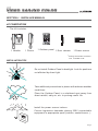
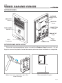
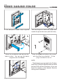
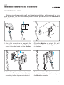
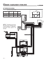
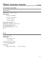
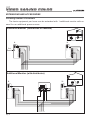
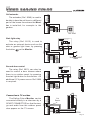
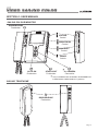
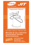
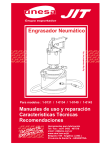
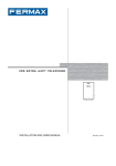
KIT
VIDEO SAILING COLOR
INDEX
SECTION I - INSTALLER MANUAL ............................................................. 4
Installation tips ..... ...................................................................... 4
Power source installation ..................................................................... 5
Outdoor panel installation ..................................................................... 6
Monitor installation ............................................................................... 8
Kit wiring diagram ................................................................................. 9
Kit technical features ............................................................................ 10
Extensions and accessories ................................................................ 11
Troubleshooting table .............. ........................................... ......... 13
SECTION II - USER MANUAL ....................................................................... 14
Controls ................................................................................................. 14
Telephone operation .............................................................................. 15
COD. 94876 V02/04
Pag 2
KIT
VIDEO SAILING COLOR
«VIDEO SAILING COLOUR KIT MANUAL Ref. 5300»
Code 94876 February 2004 edition.
This informative technical document is issued by FERMAX ELECTRONICA S.A.E.
FERMAX ELECTRONICA S.A.E., in a policy of ongoing improvement, reserves the right to
modify any of the product features referred to herein at any time without prior notice. Said
changes will be reflected in subsequent editions of the same.
ENGLISH
Pag 3
KIT
VIDEO SAILING COLOR
SECTION I : INSTALLER MANUAL
KIT COMPOSITION
The Kit includes:
+ - + -
HIGH RESOLUTION
FLAT MONITOR
PRIM 220V
HIGH PERFORMANCE
MULTIPLEXED DIGITAL SYSTEM
1
SEC. 18 Vdc
2
STOP
1 Monitor
1 Phone
1 Outdoor panel 1 Door release
*
INSTALLATION TIPS
1 Power source
Fitting accesories and flush
box included in Kit.
Do not install Outdoor Panel in backlight. Look for positions
not affected by direct light.
Take additional precautions in places with adverse weather
conditions.
Place the Outdoor Panel in a sheltered spot away from
direct rainfall, salty air, etc. to prolong useful life.
Install the power source indoors.
Current legislation demands placing 230V connectable
equipment in appropriate spots (indoors, sealed boxes...).
Pag 4
KIT
VIDEO SAILING COLOR
POWER SOURCE INSTALLATION
The Power Source must be fitted in a dry and sheltered place. Its DIN 10 format lets
you install it in any junction box or directly onto the wall using the raw plugs and
screws supplied.
DIN rail installation
Assembly
Fitting with screws
Dismantling
MA
DE
IN
50-6
0H
+1
1
A MAX
.
1.5
A
1A
FUEN
TE
AL
KIT IMEN
VID TACION
EO
12 V
VERY IMPORTANT NOTE
9
Pag 5
The Power Source must always be installed indoors. It may be fitted inside a
DIN electrical switch box.
Current legislation demands that it must be installed with a magnetothermal
switch at the power point.
KIT
VIDEO SAILING COLOR
OUTDOOR PANEL
OUTDOOR
PANEL Volume
AMPLIFIER
Grid
EX
T.
- INT.
-
TELECAMERA
Module
+
+
VM
HIG
H
CCDRESO
CAM LUTIO
ERA N
PAN
&T
ILT
CALL
Pushbutton
0°
±1
Tilt T
n & TES
Pa
MONITOR
Volume
CONNECTION
Terminals
PAN & TILT
Adjust
CT
+-
TEST
Connector
PUSHBUTTON
OUTDOOR PANEL INSTALLATION
Follow the recommendations below to install the Outdoor Panel correctly. Do not
forget to remove the plastic frontal telecamera protector when installation is completed.
1.7m
Make the holes needed to pass the
wires through
Recommended height
Pag 6
KIT
VIDEO SAILING COLOR
T.
EX
- INT.
-
+
T
EX.
+
- IN.T
-
+
+
VM
VM
TE
ST
CT
+-
Pa
°
±T 10
n ilt& TEST
CT
+-
Fit the waterproof rubber strips supplied.
Use the hinges to fasten the cables and
handle the panel with ease (with flush box).
VM
0°
±1
Tilt T
n & TES
Pa
CT
+-
AIRA
M
ACRO
L
HIG
H
CC RESO
D C LU
AM TIO
ERA N
PAN
&
TILT
Raise the pushbutton tab and put the
label in place. You can use the labels
supplied with the Panel.
Close the Panel and tighten the screws
with the Allen key supplied. Fit the
plugs included in the kit.
NOTE:
VM
0°
±1
Tilt T
n & TE S
Pa
+-
Pag 7
CT
T e telecamera incorporated in t e Outdoor
Panel as a Pan&Tilt adjust t at lets ou move
t e lens 10° in all four directions, so ou can
focus t e camera in t e desired direction
during panel installation
KIT
VIDEO SAILING COLOR
MONITOR INSTALLATION
Sailing monitors enable swift and simple installation, with no need for any
type of works. Do not remove the plastic screen protector until the Monitor is
completely installed.
3
2
90º
0m
1.6IGHT
E
H
1
1. Use a flat screwdriver to separate the
metallic support from the Monitor.
Insert it, turn and slide out the Monitor.
3
2. Place the Monitor on a rigid, flat wall.
Mark and drill the wall through the holes
in the base.
2
ION
LUT
SO
H RE NITOR
HIG
T MO
FLA
1
2
N
TIO
OLU
H RES NITOR
HIG
T MO
FLA
1
1
2
90º
3. After fixing the cables, plug in the
connectors and place the Monitor
according to the sequence indicated.
4. To take out the Monitor, insert the
screwdriver in the notch, turn and push
the Monitor upwards.
Pag 8
KIT
VIDEO SAILING COLOR
KIT WIRING DIAGRAM
WIRE SECTION AREA TABLE
LENGHT
(meters)
Thin lines
on shematics
Thick lines
on schematics
less than 300
0,5 mm2
1 mm2
75 Ohm
1 mm2
75 Ohm
1,5 mm2
75 Ohm
300 - 500
500 - 1.000
1
mm2
1 mm2
COAXIAL
RG59
A
B
C
I
P1
P2
P3
P4
CAM1
CAM2
LE
HIGH RESOLUTION
FLAT MONITOR
1
2
HIGH RESOLUTION
CCD CAMERA
PAN &TILT
M
V
V
M
NOTE: The power source may
be placed at a halfway point
in the installation. Maximum
distance from panel: 30
metres.
123 4 6
+
CT
1
2
3
4
6
7
E
+S
HIGH RESOLUTION
FLAT MONITOR
1
2
VAC
+ - + PRIM 220V
2
8 x 0,5 mm + COAX
SEC. 18 Vdc
up to 300 m.
POWER
SUPPLY UNIT
EXT.
AMPLIFIER
KIT
Ab Ab
Ab
Ab 1
+
HIGH PERFORMANCE
MULTIPLEXED DIGITAL SYSTEM
STOP
Pag 9
- CT
INT.
2 36
..........
....
..............
V M
KIT
VIDEO SAILING COLOR
KIT TECHNICAL FEATURES
Outdoor panel
Power source: 12 Vac + 18 Vdc.
Consumption:
• 40 mA. (on standby)
• 250 mA. (audio active)
• 300 mA. (camera)
• 70 mA. (lighting)
Audio power outbound: 1 W
Audio power inbound: Limited 0.25 W
Two-way adjustable volume
Operating temperature: 0 ÷ 60 ºC
IP: 34
Monitor
Power source: 18 Vdc
Consumption:
• on standby: 18 mA
• active: 400 mA
Operating temperature, Damp:
[0 , +60 °C], [0,95%]
Dimensions:
Height x Width x Depth:
210 x 79 x 42 (mm)
Pag 10
KIT
VIDEO SAILING COLOR
EXTENSIONS AND ACCESSORIES
Inreasing number of terminals
The basic equipment per home can be extended with 1 additional monitor with no
need for an additional power source.
Additional Monitor (connection in cascade)
HIGH RESOLUTION
FLAT MONITOR
1
2
HIGH RESOLUTION
FLAT MONITOR
1
2
HIGH RESOLUTION
CCD CAMERA
PAN &TILT
M1
Cut
Resist.
M2
M
V
V
M
M
V
V
M
+
CT
1
2
3
4
6
7
E
+S
+
CT
1
2
3
4
6
7
E
+S
6 3 2 1 4 + - CT
Additional Monitor (with distributor)
HIGH RESOLUTION
FLAT MONITOR
1
2
M1
REF.2448 2D IOSUT TRPI BUUT ISD OV IRD EV OI D DE OI S T2 RSI AB LUITDOARS
M
V
V
M
+
1
+
CT
1
2
3
4
6
7
E
+S
5
2
V M V M +18 4 3 V M V M
R1
75
6 3 2 1 4 + - CT
Pag 11
6
M2
HIGH RESOLUTION
FLAT MONITOR
1
2
HIGH RESOLUTION
CCD CAMERA
PAN &TILT
M
V
V
M
REF.2448
+
1
5
2
6
V M V M +18 4 3 V M V M
R1
75
+
CT
1
2
3
4
6
7
E
+S
KIT
VIDEO SAILING COLOR
Call extender
The extender (Ref. 2040) is used to
be able to hear the call tone in a different
part of the house from where the Monitor is installed, for example in the
garden.
A
B
C
I
P1
P2
P3
P4
CAM1
CAM2
LE
M
V
V
M
+
CT
1
2
3
4
6
7
E
+S
Stair light relay
The relay (Ref. 2013) is used to
activate an external device such as the
stair or garden light timer, by pressing
the button
on the Monitor.
REF. 2040
Ref. 2040
RELE LUZ DE ESCALERA
STAIRS LIGHT RELAY
REF. 2013
A
B
C
I
P1
P2
P3
P4
CAM1
CAM2
LE
LE
+18V 3
+
4
C No Nc
M
V
V
M
+
CT
1
2
3
4
6
7
E
+S
TO STAIR LIGHT
TIMER
Second door control
The relay (Ref. 2013) can also be
used to control a door release where
there is no outdoor panel, by pressing
the stair light button on the monitor. An
additional 12 V power source Ref. 2986
is required.
Connection to TV or video
The Sailing Colour Monitor can be
connected directly to a television by a
SCART CONNECTOR, so that the image and audio from the outdoor panel
also appear on the TV screen.
220 V AC
RELE LUZ DE ESCALERA
STAIRS LIGHT RELAY
REF. 2013
A
B
C
I
P1
P2
P3
P4
CAM1
CAM2
LE
PRIM 220V
LE
+18V 3
+
4
C No Nc
REF.2986
SEC. 12Vac
M
V
V
M
+
CT
1
2
3
4
6
7
E
+S
A
B
C
I
P1
P2
P3
P4
CAM1
CAM2
LE
M
V
V
M
19
17
Cut
Resist.
15
13
11
9
7
5
+
CT
1
2
3
4
6
7
E
+S
3
1
20
18
16
14
12
10
8
6
4
2
EUROCONNECTOR
Pag 12
KIT
VIDEO SAILING COLOR
TROUBLESHOOTING TABLE
SYMPTOM
POINTS TO CHECK
- Monitor on (switch on/off).
• No image appears on Monitor
- Video power source: 18Vdc between terminals «+»
and «-».
- After making a call: Voltage between ternminals «-» and
«CT» must be 10 Vdc.
- There is no short circuit between live (V) and shield (M).
- Terminal «1» connection (door release does not work
either).
• Not heard at Outdoor Panel but - Terminal «2» connection.
heard on Monitor/Telephone
- Check there is no short circuit between wires «1» and
«2».
- Check there is no short circuit between terminals «1»
and «3» (door release always active).
- Check that terminal «6» is properly connected.
• Not heard on Monitor/Phone but
heard at Outdoor Panel
- Check the terminal «3» connection (call and door release
will not work).
- Check there is no short circuit between wires «3» and
«6».
- Check that terminal «4» is properly connected.
• Call is not heard
• Feedback noise at panel and on
the Monitor/Phone
• Door release always active
• Door release activates when
phone is picked up
Pag 13
- Check the terminal «3» connection (panel-apartment
audio will not work ).
- Check there is no short circuit between wires «2» and
«6».
- Lower the Outdoor Panel volume.
- Check there is no short circuit between terminals «1»
and «3».
- Check there is no short circuit between terminals «2»
and «3».
- Check there is no short circuit between terminals «1»
and «6».
KIT
VIDEO SAILING COLOR
SECTION II : USER MANUAL
SAILING COLOUR MONITOR
DOOR RELEASE
Pushbutton
COLOUR
Control
BRIGHTNESS
Control
HIGH RESOLUTION
FLAT MONITOR
1
CONTRAST
Control
2
ON/OFF
Switch
1
AUTO-ON
Pushbutton
SAILING TELEPHONE
STAIR LIGHT
Pushbutton
*
*
2
2nd CAMERA
Connection
Only in installations with AUXILIARY TELECAMERA KIT
or ADDITIONAL VIDEO PANEL KIT (optional).
DOOR RELEASE
Pushbutton
Pag 14
KIT
VIDEO SAILING COLOR
MONITOR / TELEPHONE OPERATION
TION
OLU
H RES ITOR
HIG
T MON
FLA
1
2
Call
* When the call button on the Outdoor Panel is pressed,
a call tone is heard both at the outdoor panel and on
the monitor, the screen lights up and the ON-OFF
indicator goes off.
If there are any additional sets in the house, they will
also sound. If the call is not answered the equipment
disconnects automatically after 90 seconds.
Answer the call
* Pick up the phone handset to speak to the visitor.
TION
OLU
H RES ITOR
HIG
T MON
FLA
1
2
Duration of communication is not limited. Although the
image disappears after 90 seconds, it is possible to
continue the conversation indefinitely until the handset
is replaced.
Open the door for the visitor
* You can open the door by pressing the
TION
OLU
H RES ITOR
HIG
T MON
FLA
1
2
button at
any time.
Manual monitor activation (auto-on)
* You can switch the monitor on manually at any time
simply by pressing
.
The screen stays lit for 90 seconds before switching
off automatically.
1
TION
OLU
H RES ITOR
HIG
T MON
FLA
1
2
Pick up the phone handset to talk to the person at the
Outdoor Panel and open the door for them in the same
way as if they had called.
NOTE: T e ON/OFF s itc
must be ON. For prolonged
periods of absence, s itc off t e Monitor.
Pag 15