1
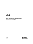
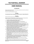
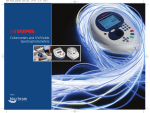
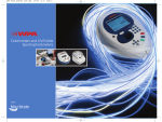
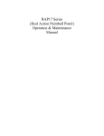
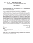
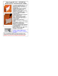
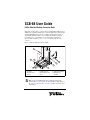
SCB-68 User Guide
68-Pin Shielded Desktop Connector Block
This guide describes how to connect and use the NI SCB-68 with 68-pin or
100-pin data acquisition (DAQ) devices and other NI products with a 68-pin
SCSI or VHDCI I/O connector. For a complete list of supported devices
and available SCB-68 features, refer to the KnowledgeBase document,
Compatible Devices and Cabling for the NI SCB-68 Terminal Block.
To access this document, go to ni.com/info and enter the info code
scb68dev.
Figure 1 shows the SCB-68 connector block.
1
2
5
3
10
8
4
5
6
9
8
1 Quick Reference Label
2 Top Cover
3 68-Pin Connector
Screws
7
4
5
6
7
Lock Washers
Shielding Screws
68-Pin I/O Connector
Base
8 Strain-Relief Screws
9 Strain-Relief Hardware
10 SCB-68 Board
Assembly
Figure 1. SCB-68 Parts Locator Diagram
Note To use the SCB-68 with devices without analog input
functionality, you must change the default switch setting. Refer to
the Using the SCB-68 in Direct Feedthrough Mode section for more
information.
What You Need to Get Started
To set up and use your SCB-68, you need the following:
❑
❑
❑
❑
❑
❑
❑
❑
SCB-68 68-pin shielded connector block kit(s)1, containing the SCB-68,
SCB-68 quick reference label, and SCB-68 User Guide
Compatible 68-pin or 100-pin DAQ device, and device documentation
The correct cable(s) for your device, as listed in the KnowledgeBase
document, Compatible Devices and Cabling for the NI SCB-68 Terminal
Block. To access this document, go to ni.com/info and enter the
info code scb68dev.
Phillips #1 and #2 screwdrivers
0.125 in. flathead screwdriver
14–30 AWG wire
Wire cutters
Wire insulation stripper
Getting Started with the SCB-68
The following cautions contain important safety information concerning
hazardous voltages and connector blocks.
Cautions To avoid electrical shock, do not remove equipment
covers or shields unless you are qualified to do so. Before removing
the cover, disconnect any live circuit from the connector block.
The chassis ground terminals on your SCB-68 are for grounding
high-impedance sources, such as a floating source (1 mA
maximum). Do not use these terminals as safety earth grounds.
Do not connect hazardous voltages (≥42 Vpk/60 VDC).
1
You can use up to two SCB-68 accessories with AO/M Series devices with two connectors and
E Series 100-pin devices.
You can use up to four SCB-68 accessories with R Series devices with four connectors, and
up to three SCB-68 accessories with R Series devices with three connectors.
SCB-68 User Guide
2
ni.com
Figure 2 shows the SCB-68 board parts locator diagram.
1
R7(G)
RC15(D)
R26(A)
RC16(B)
R27(C)
R8(F)
RC6(E)
R9(G)
RC17(D)
R28(A)
RC18(B)
R29(C)
R11(G)
C3
8
RC7(E)
C5
RC19(D)
R10(F)
R38
R30(A)
RC20(B)
R31(C)
R12(F)
RC8(E)
R13(G)
RC21(D)
R32(A)
RC22(B)
R14(F)
RC9(E)
R33(C)
7
R15(G)
RC23(D)
R34(A)
R16(F)
RC10(E)
R35(C)
R17(G)
RC25(D)
R36(A)
RC26(B)
R18(F)
RC11(E)
R37(C)
RC27(D)
R19(G)
RC2
R2
RC3
R10
RC1
RC24(B)
12
46
13
47
14
48
15
49
16
50
17
51
18
52
19
53
20
54
21
55
22
56
R3
1
35
2
36
3
37
4
38
5
39
6
40
7
41
8
42
9
43
10
44
11
45
6
S/N
SCB-681993
©COPYRIGHT
6
1
2
3
4
5
S2
ASSY182470-01 REV.B
R6(F)
RC5(E)
C1
R5(G)
C2
7
1
3
RC14(B)
R25(C)
4
S1
68
34
67
33
66
32
65
31
64
30
63
29
62
28
61
27
60
26
59
25
58
24
57
23
RC4(E)
RC13(D)
R24(A)
J1
33
34
S5 S4 S3
R4(F)
R22(A)
3
XF1
C6
R20
R21
C4
RC12(B)
R23(C)
2
3
Switches S3, S4, and S5
68-Pin I/O Connector
Breadboard Area
Fuse (800 mA, 250 V, 5 · 20 mm)
6
5
6
7
8
7
Switches S1 and S2
Screw Terminals
Signal Conditioning Areas
Temperature Sensor
Figure 2. SCB-68 Printed Circuit Board Diagram
To get started with the SCB-68, complete the following steps while referring
to Figures 1 and 2. If you have not already installed your DAQ device, refer
to the DAQ Getting Started Guide for instructions.
1. Disconnect the cable from the SCB-68, remove the shielding screws with
a Phillips #1 screwdriver, and open the top cover.
2. Attach the quick reference label to the inside of the top cover as shown
in Figure 1. For quick reference label PDFs for most compatible devices,
refer to the KnowledgeBase document, Where Can I Find
© National Instruments Corporation
3
SCB-68 User Guide
3.
4.
5.
6.
7.
SCB-68/SCB-100 Quick Reference Labels?. To access this
KnowledgeBase, go to ni.com/info and enter the info code rdwpdf.
Configure switches for the signal types you are using, as explained in the
Using the SCB-68 in Direct Feedthrough Mode section or the Using the
SCB-68 with MIO DAQ Devices section.
Adjust the strain-relief hardware by loosening the strain-relief screws
with a Phillips #2 screwdriver and sliding the signal wires through the
front panel strain-relief opening. If you are connecting multiple signals,
remove the top strain-relief bar and add insulation or padding if
necessary.
Connect the wires to the screw terminals by stripping 6.35 mm (0.25 in.)
of insulation, inserting the wires into the screw terminals, and securely
tightening the screws with the flathead screwdriver to a torque of
0.5–0.6 N ⋅ m (4.43–5.31 lb ⋅ in.).
Reinstall the strain-relief (if removed) and tighten the strain-relief
screws.
Close the top cover and reinsert the shielding screws to ensure proper
shielding.
Do not connect input voltages ≥42.4 Vpk/60 VDC to
the SCB-68. The SCB-68 is not designed for any input voltages
≥42.4 Vpk/60 VDC, even if a user-installed voltage divider reduces
the voltage to within the input range of the DAQ device. Input
voltages ≥42.4 Vpk/60 VDC can damage the SCB-68, all devices
connected to it, and the host computer.
Caution
8. Connect the SCB-68(s) to the DAQ device using the appropriate cable(s)
for your device. For a complete list of cabling options for supported
devices, refer to the KnowledgeBase document, Compatible Devices and
Cabling for the NI SCB-68 Terminal Block. To access this document,
go to ni.com/info and enter the info code scb68dev.
9. Launch Measurement & Automation Explorer (MAX), confirm that your
DAQ device is recognized, and configure your device settings. Refer to
the DAQ Getting Started Guide for more information.
10. (Optional) If you are going to take measurements with an MIO DAQ
device, configure the SCB-68 as an accessory for a DAQ device using
MAX by completing the following steps.
a. Navigate to MAX by selecting Start»Programs»National
Instruments»Measurement & Automation.
b. In the left pane of MAX, expand Devices and Interfaces, then
right-click on your DAQ device and select Properties from the
pull-down menu.
c. Select the Accessory tab from the dialog box, select SCB-68 from
the pull-down menu, then select Configure.
SCB-68 User Guide
4
ni.com
For more information about configuring the SCB-68 for a DAQ device,
refer to the Measurement & Automation Explorer Help for NI-DAQmx.
11. Test specific device functionality. Refer to the DAQ Getting Started
Guide for detailed information about running test panels in MAX.
When you have finished using the SCB-68, power off any external signals
connected to the SCB-68 before you power off your computer.
Using the SCB-68 in Direct Feedthrough Mode
High-Speed Digital I/O (DIO), NI Switch, R Series, AO Series, and
TIO Series devices, and devices without analog input functionality must use
direct feedthrough mode. Move the switches to the direct feedthrough mode
switch setting shown in Table 1.
Table 1. Direct Feedthrough Switch Setting
Switch Setting
Description
Direct feedthrough mode—Move switches S1, S2,
S1 S3, S4, and S5 to the positions shown at left. In this
S2 mode:
• All 68 signals from the device connect directly to
screw terminals.
Refer to Figure 3 for a detailed diagram.
S5 S4 S3
Device
Cable
Screw
Terminal
1
SCB-68
1
Refer to
Your Device
Documentation
for Device
Signal
Information
2
2
67
67
68
68
Temperature
Sensor
NC
Signal
Conditioning
NC
S1
S2
S5 S4 S3
Figure 3. Direct Feedthrough Mode Switch Setting
© National Instruments Corporation
5
SCB-68 User Guide
Using the SCB-68 with MIO DAQ Devices
You can take measurements with the SCB-68 and multifunction I/O (MIO)
DAQ devices, such as E/M/S Series devices, in a number of ways. Switches
S1 and S2 provide power to the signal conditioning area of the accessory.
The SCB-68 has a temperature sensor for cold-junction compensation (CJC)
to accommodate thermocouples; switches S3, S4, and S5 configure the
temperature sensor for different analog input settings. Table 2 shows the
different switch settings for MIO DAQ devices.
Table 2. MIO DAQ Device Switch Settings
Switch Setting
S5 S4 S3
S5 S4 S3
S5 S4 S3
SCB-68 User Guide
Description
MIO with disabled temperature sensor mode
(default configuration)*—Move switches S1, S2,
S1 S3, S4, and S5 to the positions shown at left. In this
mode:
S2
• The temperature sensor is not used.
• AI 0 and AI 8 are available on screw terminals.
• +5 V power provided to signal conditioning area of
the accessory.
Refer to Figure 4 for a detailed diagram.
MIO with single-ended temperature sensor
mode*,†—Move switches S1, S2, S3, S4, and S5 to
the positions shown at left. In this mode:
S1 • The temperature sensor can be read using AI 0 in
S2
referenced single-ended (RSE) mode.
• AI 8 is available on a screw terminal.
• +5 V power provided to signal conditioning area of
the accessory.
Refer to Figure 4 for a detailed diagram.
MIO with differential temperature sensor
mode*—Move switches S1, S2, S3, S4, and S5 to
S1 the positions shown at left. In this mode:
S2 • The temperature sensor can be read using AI 0 and
AI 8 in differential mode.
• +5 V power provided to signal conditioning area of
the accessory.
Refer to Figure 4 for a detailed diagram.
6
ni.com
Table 2. MIO DAQ Device Switch Settings (Continued)
Switch Setting
Description
Direct feedthrough mode—Move switches S1, S2,
S1 S3, S4, and S5 to the positions shown at left. In this
S2 mode:
• All 68 signals from the device connect directly to
screw terminals.
Refer to Figure 3 for a detailed diagram.
S5 S4 S3
*
†
Not available on Connector 1 of NI 6225/6255 devices.
Not available on S Series devices.
MIO DAQ Device
Cable
SCB-68
8
+5 V
Refer to
Your Device
Documentation
for Device AI 0 68
Signal
Information
34
AI 8
Screw
Terminal
8
Signal
Conditioning
S5
Temperature
Sensor
68
S4
34
1
2
3
1
2
3
Other
Pins
66
67
66
67
S1
S2
S3
Figure 4. MIO DAQ Device Modes Switch Settings
© National Instruments Corporation
7
SCB-68 User Guide
Connecting Signal Sources to Analog Inputs
For detailed information about connections from floating or
ground-referenced signal sources to analog inputs, refer to your device
documentation.
Refer to the SCB-68 User Manual for Advanced Functions for more
information about using the temperature sensor, taking thermocouple
measurements, and adding bias resistors and signal conditioning components
to the SCB-68.
Fuse and Power Information
Some DAQ devices provide +5 V power on pin 8 and pin 14. Pin 8 from the
DAQ device is protected by an 800 mA, 250 V, 5 · 20 mm fuse on the SCB-68,
shown in Figure 2. Shorting pin 8 to ground blows the fuse on the SCB-68.
Pin 14 is not fuse-protected on the SCB-68. Shorting pin 14 will cause the
fuse on the DAQ device to open.
If the SCB-68 does not work when you power on the DAQ device, check the
switch settings, then check the fuse on the SCB-68, shown in Figure 2, and
the output fuse (if any) on the DAQ device. Littelfuse part number 235.800
(www.littelfuse.com) is a suitable replacement fuse. Before replacing
any fuses, check for short circuits from power to ground.
Refer to the SCB-68 User Manual for Advanced Functions for information
about filtering the power on the SCB-68.
Where to Go from Here
Refer to the SCB-68 User Manual for Advanced Functions, available from
ni.com/manuals, for information about the temperature sensor,
thermocouple measurements, bias resistors, soldering components on the
SCB-68, filtering, current input measurements, and accessory specifications.
National Instruments, NI, ni.com, and LabVIEW are trademarks of National Instruments Corporation. Refer to the Terms of Use section
on ni.com/legal for more information about National Instruments trademarks. Other product and company names mentioned
herein are trademarks or trade names of their respective companies. For patents covering National Instruments products/technology,
refer to the appropriate location: Help»Patents in your software, the patents.txt file on your media, or the National Instruments
Patent Notice at ni.com/patents.
© 1994–2009 National Instruments Corp. All rights reserved.
371745C-01
Mar09