1
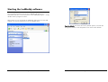
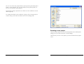
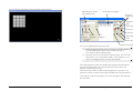
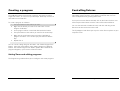
Ledbuddy Setup User Manual
©2009 Abstract AVR and Sabre Technology
Tel: 0116 278 8078
http://www.abstractavr.com
Page 24
LedBuddy Setup Software
Page 2
Page 23
Upgrading LedBuddy panel software
The LedBuddy panel software can be easily upgraded to the latest
version, which may add additional features or fix problems. The software
upgrade file is available from the AbstractAVR website.
1. Connect the LedBuddy panel to a PC by USB. Remove the RJ45
connection to the LED installation or switch off the power to the
LED installation so that the panel is powered only by USB.
2. Copy the UPGRADE.HEX file to the LedBuddy’s removable drive
(the root folder).
3. Disconnect the USB cable, then reconnect it.
4. The LedBuddy panel should show a pattern of sequencing lights
on the 1-8 buttons. When the Up/Down arrow buttons flash, the
upgrade is finished. The PC may pop up a warning of a problem
with a USB device; this may be safely ignored.
Ensure that the power to the panel is not disconnected during the
upgrade.
5. At the end of the upgrade, disconnect the USB cable again, then
reconnect it.
6. When you reconnect the power, the LedBuddy will delete the
upgrade.hex file from its disk and restart with the new software.
If the upgrade does not complete successfully, the LedBuddy will go back
to its previous version of software, however it will not delete the
upgrade.hex file. This means that it will try to carry out the upgrade every
time you connect the power. To get out of this, hold down the on/off
button while you connect the panel. The LedBuddy panel will then start
normally and you can manually delete the upgrade.hex file using
Windows.
Page 22
Introduction
This booklet guides you through how to program the AVR LedBuddy
controller.
The LedBuddy is a simple yet powerful wallpanel controller for LED
lighting. All programming and configuration is carried out using a PC
application, connected to the LedBuddy panel by USB.
Connecting the LedBuddy panel
The LedBuddy panel is connected to your PC using a mini-USB cable. The
panel will draw power from the USB port. No drivers are needed to
operate the panel.
If you also connect the panel to your LED lighting installation, the lights
will follow your programming on the PC. This is very useful to check the
actual colours you are programming, as the colours represented on the
PC monitor will vary between different monitors and may not match the
actual LED colours. While the PC is operating the lights, you may notice
some “steppiness” as the lights fade in and out. This is normal during
programming and will not occur once the panel is programmed and
installed.
Connect the LedBuddy panel to your lighting installation using a standard
RJ45 cable. If you are connecting to an AbstractAVR system, most of the
drivers can provide a power feed for the LedBuddy panel. If not, you can
connect any DC power supply from 7-48V to pins 6 (positive) and 8
(negative) of the RJ45 cable.
Page 3
Starting the LedBuddy software
The LedBuddy application is stored on the LedBuddy device itself. When
you connect the panel to your PC, the LedBuddy will appear as a
removable disk drive. On the disk drive is the LedBuddy program – simply
double click the program to start it.
Alternatively you can download the LedBuddy application from the AVR
website or it may be supplied on a CD or USB pen drive.
Reset to defaults will restore the factory default options, and will also
change the colours on the Properties screen back to the defaults.
Page 4
Page 21
other panel acts a Slave and just sends commands to the Master. The
Slave panel does not require any programming.
Allow user to change colour/speed enables the user to modify the colour
of a (static) program by holding the program button while pressing the
up/down buttons. If used on a changing program, the program will stop
at the most recent step. The user can modify the speed of a changing
program by pressing both up & down together (buttons flash) then press
up or down to change the speed. Changes to colour and speed are
temporary and are forgotten as soon as a new program is selected.
External control inputs sets the functions of the external input terminals on
the LedBuddy panel.
• Infrared remote, with the addition of an IR sensor module, allows
control using a TV-style remote control.
• Remote on/off switch allows you to connect a standard light
switch to operate the Ledbuddy blackout control in the style of a
2-way switch.
• Remote Dimmer knob allows you to connect a potentiometer to
act as a dimmer. A 0-10V signal may also be connected, with
the addition of a 0-10V interface module (or a resistor divider to
make the signal 0-5V).
• PIR sensor allows you to connect a PIR module which will
automatically switch on a program for a set time. The PIR Setup
button allows you to configure this – you select which program
will be activated, and for how long it will stay on. If the PIR is
retriggered, the timer will start again. If “Manual Programs
Disable PIR” is checked, any program you manually select will
prevent the PIR program from activating – this can be useful if
you only want the PIR to activate when nothing is turned on.
Note that the blackout button on the Ledbuddy panel does not
affect the PIR program – the program will activate even if the
blackout button is selected.
Loading a project
The programming and configuration of the LedBuddy panel is stored in a
LedBuddy project. You can store as many different projects as you want.
When your project is
complete and you are ready
to copy it to the LedBuddy
panel, you use the “Upload
to LedBuddy” button. You
can also load a project from
a LedBuddy panel back to
the computer for editing, for
which you use the
“Download from LedBuddy”
button. There are also
options on the File menu for
these functions.
Download
from LedBuddy
When you Upload a project to the LedBuddy, you will be asked if you
want to backup the project currently stored on the LedBuddy. If you say
No, the project on the LedBuddy will be overwritten.
Loading a project from disk
LedBuddy projects are stored on your disk with the file extension .lbp. The
normal Windows interface is used to load a project.
The “Trigger” indicator will light when the PIR is triggered if the
LedBuddy panel is connected by USB (there is a slight delay).
Page 20
Upload
to LedBuddy
Page 5
Setting LedBuddy options
Click the Tools menu, then select Options.
Saving a project to disk
The “Save” option, or disk button on the toolbar, will save the current
project using its current name.
If you wish to modify an existing project and save it under a different
name, use the “Save As…” option and enter a new name.
The top options set how the program works.
Panel 8, 16, and 8x8 button options set the type of LedBuddy panel you
are programming for. 8 Button is the single-pattress panel. 16 and 8x8
are both for the double pattress panel, and allow 16 individual programs
or 8 pages of 8 programs (64 in all) to be configured. In 8x8 mode the 8
leftmost buttons are the page buttons.
Show Key Legends will display the names of programs next to the keys on
the simulated panel.
Autosave changes will cause the project to be automatically saved (to its
current project name) every 5 minutes.
The bottom options set how the LedBuddy panel works.
Blackout Fade time lets you set a fade in and fade out time for the
blackout button (the red button). This can be from 0 to 10 seconds in 0.1
second steps.
Key Glow turns on a faint background glow on the LedBuddy keys. This
can help you to find the panel in a dark environment.
Slave panel mode sets this panel to be a Slave. This is used in a “2-way
switching” situation where you might want two control positions in a
room. One of the panels contains the programs and is a Master, the
Page 6
Page 19
You can now select the grouped fixtures just by pressing the hotkey (the 2
button, in this example). You can record steps just by pressing Enter, so
you can very quickly create programs.
To set further groups, repeat from 2. A fixture can be included in several
different groups.
To modify which fixtures are included in a group, click on the group you
want to change, select the new fixtures and click “modify group”.
Creating a new project
The New Project option will clear all settings back to the default (after
asking you if you want to save the current settings).
The first time you save a new project, you will be asked for the project
name.
Page 18
Page 7
Setting up fixture groups for speedy programming
Guide to the controls
Programming window:
Sets program steps,
timings and names
Control editor: Allocates
programs to the buttons
When programming a complicated pattern it can take quite a while to
select and deselect fixtures to make the pattern.
LedBuddy allows you to group fixtures together and allocate them to a
“hotkey” so that you can select a set of fixtures at the press of a button.
This can save a lot of mouse clicking.
1. Right click in the simulator window and select “Set Fixture
Groups/Hotkeys”
2. Select the fixtures you wish to group.
3. Click “Create group”
4. If you wish to change the name, type a new name in the Group
Name box.
5. To set a hotkey, press the key or combination of keys you want to
use (which is shown in the “Current Hotkey” box).
Properties window:
controls colours and
fixture settings
Simulator window: shows
a simulation of the LED
fixtures
Page 8
6. Click “Assign hotkey”
Page 17
SuperPrograms
Setting up fixtures (patching)
You can create a program which runs a sequence of other programs. This
can be useful for unattended operation, or just for some variety. The
Insert Program button will create a step which runs another program. The
Wait Time sets how long this program will run for, before the next step of
the superprogram becomes active.
Insert program
LedBuddy should come with a sample fixture setup, and you can also
download LedBuddy projects from the AVR website. However it is also
very easy to set up your own fixture patch.
1. From the File menu select “New Project”
2. A blank project is created for you.
3. Right-click on the simulator window and select “Add multiple
fixtures”. (Or left click on the simulator window and use the
option on the Edit menu)
1. Click Insert Program button.
2. Select the Program you wish to run. You can’t use an existing
SuperProgram. The program name will be shown in the step list.
3. Enter the time you want the program to run for in the Wait time
box. You can enter times from 0 to 3200 seconds (just over 50
minutes) in 0.1 second steps.
The subprogram will run with its own fade, wait and loop settings as
programmed.
If a program is called from a Superprogram, you can’t make that
program into a superprogram itself. In other words, only one level of subprogram is possible, you can’t have a subprogram calling another
subprogram.
Page 16
4. Select the fixture type as RGBW, RGB or RGBD, depending on
what control channels your fixtures require.
5. Set the DMX start address for the first fixture. The others will be
set automatically.
6. Set a name for the fixtures. In this example they will be named
Fixt1 to Fixt16.
7. Set the number of fixtures to add.
8. Set the visual appearance the fixtures will have in the simulator
window.
9. Set the visual arrangement of the fixtures in the simulator
window. In this example we are adding 16 fixtures in a 4x4 grid.
10. Click Add Fixtures.
Page 9
The new fixtures will appear in the simulator window like this:
Select program to edit
and change name
List of steps in program
Timing for
current step
Update/save current
step
(overwrites step)
Insert new step
Copy
program
New
Delete
program
program
Insert program
Test
program
Move step down
in list
Move step up in list
You can set individual times for each step.
Delete current step
1. Select the step to change. You can change a number of steps at
once by holding down Shift+Click to select a group, or
Ctrl+Click to select individual steps.
2. Enter the new times in the Fade or Wait time box. You can enter
times from 0.1 sec up to about 1h30m. Use the letters “h” “m”
and “s” to designate hours, minutes and seconds.
The “Loop program” button sets whether the program will loop back to
the start when it finishes. If not, the last step will remain until a new
program is selected by the user.
The “Sound Trig” button enables sound triggering for a program. You
should set a short or zero time for Fade and Wait when using sound trig.
To change the name of a program, click in the “Program” box and type
the new name.
Page 10
Page 15
Creating a program
The LedBuddy buttons each activate a program. A program may be a
single static colour, or may have up to 255 steps. Each step can have its
own fade time and wait time.
To create a program on a button:
1. Set up the fixtures to the colours you want.
2. Right click the button you want to use and select “Create
Program On Button”.
3. A new program will be created and allocated to the button.
4. Set up the fixtures to the colours you want for the second step.
5. Right click the same button again and select “Add step to
program on button”. You can also just press Enter to add the
step.
Controlling fixtures
To control fixtures, you can either select them using the mouse by
individually clicking on them, or by drawing a selection box. You can
select multiple fixtures by pressing Shift+Click.
Once you have some fixtures selected, click on the Colour Picker or one
of the sample colour boxes to set the colour of the selected fixtures.
You can also select the “Paintbrush” tool, and click and drag across
fixtures to set them to the last colour used.
The “Eyedropper” tool allows you to pick a colour from anywhere on your
computer screen.
6. Repeat from 4.
You can use the “Assign Program to button” and “Delete Program from
button” right-click commands to assign existing programs to different
buttons. The “Delete Program from button” option does not delete the
program altogether, it just removes it from the button.
Setting Times and editing programs
The Programming window allows you to configure and create programs.
Page 14
Page 11
you can lock the fixtures in position by right clicking in the simulator
window and selecting “Lock Fixture Positions”.
Fixture settings
If you want to control the individual DMX channels of the installation
rather than picking colours, you can open the DMX slider window by
clicking the Sliders button to the right of the colour picker.
The Sliders window always stays on top and can be positioned anywhere
on your computer screen.
Selection tool
Paintbrush tool
Eyedropper tool
Colour picker control
Show DMX sliders
Dimmer control
Recently used colours
Last colour used
Preset colours (top row)
Favourite colours (bottom row)
You can edit the settings of a fixture at any time by selecting the fixture,
then changing its settings in the boxes at the top of the Properties window.
You can change the “Favourite colours” by selecting the new colour on
the colour picker, then right-click the favourite colour you want to change
(only the bottom row of colours can be changed).
Use the mouse to change the slider values.
Hold down Shift to change all slider values simultaneously.
The cursor up/down buttons will also change the last slider you clicked
on.
The cursor left/right buttons will change which slider is selected.
Home button will set a slider to zero, End button will set it to full.
Only the sliders which are applicable to the current fixtures will be
enabled.
Exact DMX values may be entered into the boxes at the bottom.
You can move the fixtures around in the Simulator window to help
visualise your installation. If you find you are moving fixtures accidentally,
Page 12
Page 13