1
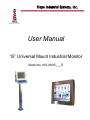
Hope Industrial Systems, Inc. User Manual 15” Universal Mount Industrial Monitor Model No. HIS-UM15-___E TABLE OF CONTENTS Safety and Regulatory Information ............................................................. 3 Warning ..................................................................................................... 3 FCC Notice ................................................................................................ 3 Factory Preset Timing................................................................................ 4 Setting the Timing Mode .............................................................................. 5 OSD and Power Lock Settings .................................................................... 5 Adjusting the Screen Image......................................................................... 6 Main Menu Controls ..................................................................................... 8 Installation Instructions ............................................................................. 11 Preparing for Installation .......................................................................... 11 Installation using VESA mounting............................................................ 12 Installation using the bench top mounting option.....................................12 Installation using yoke and pedestal mounting option .............................13 Installation using fixed pedestal mounting option ....................................15 Cleaning ....................................................................................................... 16 Resistive Touchscreen model ................................................................. 16 Tempered Anti-Reflective Glass Window ................................................16 Acrylic Window ........................................................................................ 16 Troubleshooting ......................................................................................... 17 Drawings ...................................................................................................... 18 Front View (all models) ............................................................................ 18 Side and Rear View of Standard Models .................................................18 Bottom, Side and Rear View of Extended Rear Cover Models ...............19 Specifications.............................................................................................. 19 Display ..................................................................................................... 19 Video ........................................................................................................ 20 Electrical .................................................................................................. 20 Environmental .......................................................................................... 20 Functional ................................................................................................ 21 Compliance .............................................................................................. 21 Enclosure ................................................................................................. 21 Physical.................................................................................................... 21 VGA Pin assignment................................................................................ 21 Warranty Statement .................................................................................... 23 2 Safety and Regulatory Information Warning To prevent fire or shock hazard, do not expose the unit to rain or moisture. Dangerously high voltages are present inside the unit. Do not disassemble the unit. Refer servicing to qualified personnel only. This equipment is not intended for use in critical applications where its failure to operate would create immediate life threatening circumstances. Applications including, but not limited to, nuclear reactor control, aerospace navigation systems and life support systems are not appropriate for this product. This product is a UL Listed Component and must be used with a listed computer. A readily accessible disconnect device shall be incorporated in the building installation wiring. Installation shall be in accordance with the National Electric Code and authorities having jurisdiction. FCC Notice This equipment has been tested and found to comply with the limits for a Class A digital device, pursuant to Part 15 of the FCC Rules. These limits are designed to provide reasonable protection against harmful interference when the equipment is operated in a commercial environment. This equipment generates, uses and can radiate radio frequency energy and, if not installed and used in accordance with the instruction manual, may cause harmful interference to radio communications. Operation of this equipment in a residential area is likely to cause harmful interference in which case the user will be required to correct the interference at his own expense. Any changes or modifications not expressly approved by the grantee of this device could void the user’s authority to operate the device. 3 Factory Preset Timing Resolution Horizontal Frequency (KHz) Vertical Frequency (Hz) Pixel Clock (MHz) IBM, 640 x 350 31.469 70.086 25.175 +/- IBM, 640 x 480 31.469 59.940 25.175 -/- IBM, 720 x 400 31.469 70.087 28.322 -/+ VESA, 640 x 480 37.500 75.000 31.500 -/- VESA, 640 x 480 37.861 72.809 31.500 -/- VESA, 800 x 600 35.156 56.250 36.000 -/- VESA, 800 x 600 37.879 60.317 40.000 +/+ VESA, 800 x 600 46.875 75.000 49.500 +/+ VESA, 800 x 600 48.077 72.188 50.000 +/+ *VESA, 1024 x 768 48.363 60.004 65.000 -/- *VESA, 1024 x 768 56.476 70.069 75.000 -/- *VESA, 1024 x 768 60.023 75.029 78.750 +/+ * 4 Factory recommended timings for best picture quality Sync Polarity (H/V) Setting the Timing Mode Setting the computer’s timing mode is important for maximizing the quality of the screen image and minimizing eye strain. The timing mode consists of the screen resolution (ex. 1024 x 768) and the refresh rate (ex. 60 Hz or vertical frequency). After setting the computer’s timing mode, use the OSD (On Screen Display) controls to adjust the screen image. For the best picture quality set your LCD display timing mode to: 1024 x 768 @ 60Hz. To set the timing mode on a computer running Microsoft Windows: Set the resolution: Right-click on the Windows desktop > Properties > Settings > adjust the resolution. Set the refresh rate: See your graphic card’s user guide for instructions. Warning: Do not set the graphics card in your computer to exceed the maximum refresh rate of 75 Hz; doing so may result in permanent damage to your LCD display. OSD and Power Lock Settings OSD Lock: Press and hold the up arrow for 10 seconds. Locking the OSD disables the OSD buttons. If any buttons are pressed, the message OSD Locked will display for 5 seconds. OSD Unlock: Press and hold the up arrow again for 10 seconds. for 10 seconds. Locking the power Power Button Lock: Press and hold the down arrow button disables it. If the power button is pressed, the message Power Button Locked will display for 5 seconds. With or without this setting, after a power failure, your LCD display’s power will automatically turn ON when power is restored. Power Button Unlock: Press and hold the down arrow again for 10 seconds. 5 Adjusting the Screen Image Use the buttons on the rear control panel to display and adjust the OSD controls which display on the screen. Main Menu With OSD Controls • Power Light: o Green = On o Orange = Power Saving • Standby Power • Contrast Adjustment • Scrolls through menu options and adjusts the displayed control 6 • Displays the Main Menu or exists the control screen, saving adjustments • Auto Image Adjust • Displays the control screen for the highlighted control 1. To display the Main Menu, press button [1]. Note: All OSD menus and adjustment screens disappear automatically after about 15 seconds. This is adjustable through the OSD timeout setting in the setup menu. 2. To select a control to adjust, press or to scroll up or down in the Main Menu. 3. After the desired control is selected, press button [2]. A control screen like the one shown below appears. The area at the bottom of the screen shows the current functions of buttons 1 and 2. 4. To adjust the setting, press the up or down buttons. 5. To save the adjustments and exit the menu, press button [1] twice. The following tips may help optimize your display: Adjust the computer’s graphics card so that it outputs a 1024 x 768 @ 60 Hz video signal to the LCD display. (Look for instructions on “changing the refresh rate” in the graphics card’s user guide.) If necessary, make small adjustments using H. POSITION and V. POSITION until the screen image is completely visible. (The black border around the edge of the screen should barely touch the illuminated “active area” of the LCD display.) 7 Main Menu Controls Adjust the menu items shown below by using the up Control and down buttons. Explanation Auto Image Adjust automatically sizes, centers, and fine tunes the video signal to eliminate waviness and distortion. Press the [2] button to execute Auto Image Adjust. Note: Auto Image Adjust works with most common video cards. If this function does not work on your LCD display, lower the video refresh rate to 60 Hz and set the resolution to its pre-set value. Contrast adjusts the difference between the image background (black level) and the foreground (white level). Brightness adjusts background black level of the screen image. Color Adjust provides several color adjustment modes, including preset color temperatures and a User Color mode which allows independent adjustment of red (R), green (G), and blue (B). The factory setting for this product is 6500K (6500 Kelvin). sRGB – This is quickly becoming the industry standard for color manage8 ment, with support included in many of the latest applications. Enabling this setting allows the LCD display to more accurately display colors the way they were originally intended. Enabling the sRGB setting will cause the Contract and Brightness adjustment to be disabled. 9300K – Adds blue to the screen image for cooler white (used in most office settings with fluorescent lighting). 6500K – Adds red to the screen image for warmer white and richer red. 5400K – Adds green to the screen image for a darker color. User Color – Individual adjustments for red (R), green (G), and blue (B). To select color (R, G, or B) press button [2]. or . To adjust selected color, press When all color adjustments are complete, press button [1] twice. Information displays the timing mode (video signal input) coming from the graphics card in the computer, the LCD model number, and the serial number. See your graphics card’s user guide for instruction on changing the resolution and refresh rate (vertical frequency). Note: VESA 1024 x 768 @ 60 Hz (recommended) means that the resolution is 1024 x 768 and the refresh rate is 60 Hertz. H./V. Position (Horizontal/Vertical Position) moves the screen image left or right and up or down. Press button [[2] to toggle between Horizontal and Vertical. The Horizontal setting moves the screen image to the left or to the right. The Vertical setting moves the screen image up and down. H. Size (Horizontal Size) adjusts the width of the screen image. 9 Fine Tune sharpens the focus by aligning text and/or graphics with pixel boundaries. Note: Try the Auto Adjust function before using the Fine Tune control. Sharpness adjusts the clarity and focus of the screen image. Setup menu displays the menu shown below: Language Select allows the user to choose the language used in the menus and control screens. Resolution Notice advises the optimal resolution to use. OSD Position allows the user to move the on-screen display menus and control screens. 10 OSD Timeout sets the length of time the on-screen display screen is displayed. For example, with a “15 second” setting, if a control is not pushed within 15 seconds, the display screen disappears. OSD Background allows the user to turn the On-Screen Display background On or Off. Memory Recall returns the adjustments back to factor settings if the display is operating in a factory Preset Timing Mode listed in the Specifications of this manual. Installation Instructions Preparing for Installation Important! Perform the following steps BEFORE Installation of the monitor. 1. Ensure that sufficient power is available. 2. Ensure that sufficient space is available to allow for proper airflow around the enclosure. 3. Ensure that the air temperature around the unit (top and bottom) will not exceed the rated specifications of the unit. The maximum rated temperature of the HIS-UM15 is 45°C (113°F). Also, remember that even though this product is designed to operate at 45°C , the life span of any electronic device is shortened when it is consistently operated at high temperatures. Therefore it is wise to take steps to keep the temperature of the ambient air around the unit as low as possible. 4. Ensure that the ambient humidity of the air around the unit does not exceed the rated specifications for the unit The maximum rated humidity for the HIS-WL15 is 90% non-condensing 11 Installation using VESA mounting All units come standard with a 100mm square VESA mounting pattern with M4 threads (75mm VESA pattern is also available on the NEMA 12 version). If this mounting method is used, consider the following: M4 screws should not protrude into the rear cover by more than 1/4”. The capacity of the arm or mounting plate selected should take into account the total weight of the monitor and its center of gravity. For NEMA 4/4X applications, the mounting interface should be properly sealed to prevent egress of water. Sealing washers are provided for this purpose. Installation using the bench top mounting option 1. Prepare the mounting surface for installation of the bench mounting plate referring to the illustration above. 2. Free the bench mounting plate from the assembly by removing the cotter pin, yoke locking nut and stainless steel washer. 3. Install the bench mounting plate into the mounting surface using the ¼ - 20 screws provided or longer screws as required. 12 4. Reassemble the yoke to the bench mounting plate per the illustration above. For NEMA 4/4X applications, replace the cotter pin with a 6-32 x ¾” long screw and sealing washer. Also insure that the bench mounting plate is sealed between itself and the mounting surface. Installation using yoke and pedestal mounting option 1. Prepare the mounting surface for installation of the pedestal by referring to the illustration above. 2. Install the pedestal using appropriate hardware and methods for the mounting surface selected taking strength, cable routing and sealing into consideration. 3. Free the pedestal top plate from the assembly by removing the retaining screw, yoke locking nut, stainless steel washer and 4 ¼-20 screws. 4. Position and support the monitor and yoke assembly so that cables exiting from the monitor can be easily routed into the top of the pedestal. 5. Install the pedestal top plate and polyethylene friction plate using the four ¼-20 screws insuring all cabling inside the pedestal has been fed through the top of the pedestal top plate. 6. Connect all communication and power cables to the monitor insuring all remaining hardware has been threaded onto the cables in their proper order per the illustration 13 above. Connectors that do not have a locking mechanism should be sheathed in heat shrink tubing to insure that they do not come loose inside the pedestal. Note: The ¾” conduit and other sealing hardware are not required for NEMA 12 monitors or NEMA 4/4X monitors with the 4-cable gland. 14 7. Install the monitor and yoke assembly onto the top of the pedestal with the stainless steel washer, the yoke locking nut and the retaining screw. Insure that there is a sealing washer underneath the retaining screw. 8. Feed all connectors and excess cabling inside the top of the pedestal. 9. Screw conduit elbow onto top of pedestal taking care to position the direction of the conduit to allow free tilting of the monitor without interference. Installation using fixed pedestal mounting option 15 Cleaning Resistive Touchscreen model Any standard glass cleaner can be used to clean the touchscreen. Always spray the glass cleaner on the cloth or towel and then clean the touchscreen. Glass cleaner sprayed directly on the monitor could possibly leak inside a non-sealed unit and cause damage. Vinegar or ammonia will not hurt the touchscreen. Again, spray the cloth and then clean the touchscreen. Tempered Anti-Reflective Glass Window Use any standard glass cleaner as long as there is no abrasive or oily content. The antireflective coatings are physically part of the surface of the glass and resist degradation to the Military Specifications. Acrylic Window The acrylic front bezel can be cleaned in the same manner as the touchscreen or glass window. 16 Troubleshooting Note: For troubleshooting with a KVM extender installed, please refer to the Installer/User Guide that comes with that equipment. Blank Screen After installing the power adapter and connecting I/O cable to a PC, the monitor displays a blank screen. • Press the power button and check to see if the power LED is lit. • If the LED turns green, make sure the PC is powered on. Make sure all cables are connected. • If the LED turns orange, check to see if the PC is in the power saving mode by pressing any keys on the keyboard. Rolling Screen • • • • • Change PC display resolution to 1280x1024 at 60 Hz refresh. Unplug the power adapter to monitor and then plug it in again. Press monitor power button again. Reset the monitor to the original factory setting. Press “Auto” button. • • Press the “Auto” button. Make sure the PC display resolution is not set greater than 1280x1024 at 75hz. Make sure the PC display resolution matches one of the factory preset timings in this manual. Change the PC display resolution to 1024x768 at 60hz. Reset the monitor to the factory setting. Press the “Auto” button. Unstable Screen • • • • Screen is not perfect • • • Make sure the PC display resolution matches one the factory preset timings shown in this manual. Recall factory setting. Refer to panel controls and OSD functions in this manual. Fine tune the picture by performing the following adjustments in this order – pitch, phase, and position. Refer to OSD functions in this manual. Auto Adjustment Locked • To unlock press the MENU and AUTO buttons simultaneously for at least 5 seconds. (see page 7) 17 Drawings Front View (all models) Side and Rear View of Standard Models 18 Bottom, Side and Rear View of Extended Rear Cover Models Specifications Display Type Size Image size Native resolution Plug and Play Minimum resolution Pixel pitch Number of colors Thin-film transistor (TFT) Active Matrix Liquid Crystal 15” diagonal 12.0” (304mm) x 9.0” (228mm) XGA (1024 x 768) DDC1/2B compatible` VGA (640 x 480) 0.297mm x 0.297mm 16 million 19 Viewing Angle (Hori/Vert) Brightness (white) Contrast ratio Back light Screen protector (when not shipped with touchscreen) 150° / 125°, typical 2 250 nits (cd/m ) max 400:1 (typical) Two CCFTs (Cold Cathode Fluorescent Tube); 35,000 hours brightness half-life; replaceable Tempered glass to ANSI-Z97.1 SPEC; AR coated on both sides; 98% Transmission of light; 99% Reduction of glare; 53% UV blocking; 30% NIR Blocking; proprietary hydrophobic coating on outside reduces fingerprint smears, repels liquid spills and makes glass easy to clean. Video Input connector Input signal format HD-15 (optional BNC input) Horizontal scan 30kHz – 62kHz Supported Video Standards Std VGA – 640x480 @ 60Hz SVGA – 800x600 @ 60Hz XGA – 1024x768 @ 60Hz (Native) Vertical scan 50Hz – 85Hz Response rate (typical) 16ms RGB Analog video 0 – 0.7V p-p – sep V and H sync Electrical Monitor input 100VAC – 240VAC, 50/60Hz (+/- 3Hz) Power consumption Less than 30W Power management DPMS/energy star, < 1W Environmental Temperature 0-45°C Humidity 20% to 90% non-condensing Shock 30g (1/2 sine, 11 msec.) Vibration 0.006 inch p-p 15-57Hz, 1.0g 57-640Hz sine Altitude Operating: up to 10,000 feet; Non-operating: up to 40,000 feet 20 Functional Panel controls (rear access) Power, 1, down, up, 2 OSD (On Screen Display) controls Auto image adjust, contrast, brightness, color adjust (9300, 6500K default, 5400K, user color), information (mode, model number, serial number), manual image adjust (H size, H position, V position, fine tune, sharpness), setup menu (language, resolution notice, OSD position, OSD timeout), memory recall Touch screen option 5-wire resistive system; emulates a mouse; Serial RS-232 or USB interface to host computer Compliance Electrical UL 60950 3rd Edition, cUL recognized component; FCC Class A RoHS Environmental Enclosure Type Self-contained; black powder coated steel or stainless steel Panel rating NEMA 2, 12, 4 or 4X; (NEMA 4 built to IP65 standards) Physical Depth 3.3” (84mm) for NEMA 2 and 5.7” (145mm) for NEMA 4X Dimensions – Height, Width 16.4” (417mm) W x 13.0” (330mm) H Depth Standard Model - 2.8” (71mm) Extended Rear Cover Model - 5.5” (138mm) Net weight Standard Model, Black Carbon Steel – 12.55 lbs Standard Model, Stainless Steel – 14.85 lbs Extended Rear Cover Model – 19.00 lbs. Shipping weight Standard Model, Black Carbon Steel – 15 lbs Standard Model, Stainless Steel – 18 lbs Extended Rear Cover Model – 30 lbs. VGA Pin assignment Pin No. Signal Pin No. Signal 21 1 2 3 4 5 6 7 8 22 Red Green Blue Ground Ground Ground Ground Ground 9 10 11 12 13 14 15 No pin Ground Ground SDA H. sync V. sync SCL Warranty Statement Who is Covered? This warranty covers the purchaser of this product only and is not transferable without our written consent. What Does This Warranty Cover and What is the Period of Coverage? The warranty remains in force for a three year period beginning on the date we invoice you for the product unless it is a keyboard, for which the warranty period is one year. If HIS repairs or replaces a product under warranty, its warranty term is not extended. What Will We Do to Correct Problems and How Do You Get Service? We will repair or replace (at our sole option) any part of the unit which proves to be defective. Replacement parts may be new or refurbished and will meet the same specifications of the original parts or unit. We will return the product to you, by the shipping method we choose in the U.S.A. at our expense. You must pay for shipments to locations outside of the U.S.A. In order to receive warranty service you must get prior approval from HIS. To request warranty service you can telephone us at 678-762-9790 or send an email to [email protected]. If we determine that warranty service is needed we will give you a Return Material Authorization (RMA) number. This RMA number must be conspicuously marked on the outside of the shipping box. HIS will not accept shipments not accompanied by the RMA number. You must ship or deliver the product to HIS Freight prepaid. Pixel Faults Permanently dark or bright pixels can happen to TFT displays. Five or less permanently dead pixels (out of 1.3 million) do not make a good case for exchanging the unit. Please contact our Customer Service Department if the number of pixel faults exceeds the above-mentioned figure. What Does This Warranty Not Cover? This warranty does not cover equipment which has been damaged due to misuse, abuse or accident such as: operating the equipment outside of published specifications; exposure to chemicals or gasses not covered by specified NEMA standards; displaying fixed images for long periods of time resulting in afterimage effects; improper or unauthorized repair by anyone other than HIS or a service agency authorized by HIS to perform such repairs; fire, flood, “acts of God”, or other contingencies beyond the control of HIS. HIS’ RESPONSIBILITY FOR MALFUNCTIONS AND DEFECTS IN HARDWARE IS LIMITED TO REPAIR AND REPLACEMENT AS SET FORTH IN THIS WARRANTY STATEMENT. HIS SHALL NOT BE LIABLE FOR DIRECT, INDIRECT, INCIDENTAL, CONSEQUENTIAL, OR OTHER TYPES OF DAMAGES RESULTING FROM THE USE OF ANY HIS PRODUCT OTHER THAN THE LIABILITY STATED ABOVE. THESE WARRANTIES ARE IN LIEU OF ALL OTHER WARRANTIES EXPRESS OR IMPLIED, INCLUDING, BUT NOT LIMITED TO, THE IMPLIED WARRANTIES OF MERCHANTABILITY OR FITNESS FOR A PARTICULAR PURPOSE. SOME STATES DO NOT ALLOW THE EXCLUSION OF IMPLIED WARRANTIES OR THE LIMITATION OR EXCLUSION OF LIABILITY FOR INCIDENTAL OR CONSEQUENTIAL DAMAGES SO THE ABOVE EXCLUSIONS OR LIMITATIONS MAY NOT APPLY TO YOU. YOU ARE CAUTIONED THAT THE PERFORMANCE OF THIS PRODUCT CAN BE AFFECTED BY MANY FACTORS, SUCH AS SYSTEM CONFIGURATION, SOFTWARE, APPLICATION, AND OPERATOR CONTROL OF THE SYSTEM. IT IS YOUR RESPONSIBILITY TO DETERMINE SUITABILITY OF THIS PRODUCT FOR YOUR PURPOSE AND APPLICATION. 23 Hope Industrial Systems, Inc. 1325 Northmeadow Parkway Suite 100 Roswell, GA 30076 www.HISmonitors.com Publication UM15 Rev E September, 2006 24 2006 Hope Industrial Systems, Inc.