1
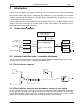
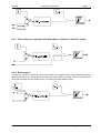
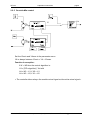
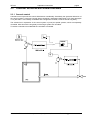
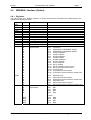
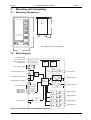
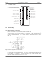
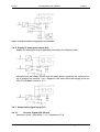
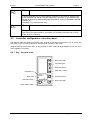
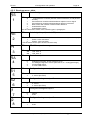
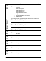
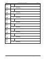
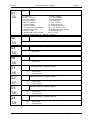
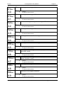
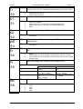
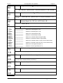
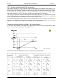
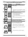
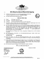
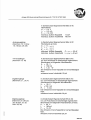
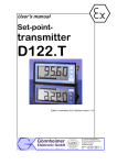
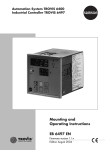
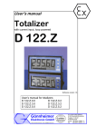
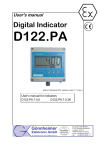
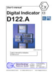
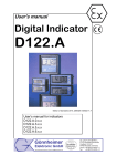
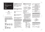
User's manual
E Ex i - controller
PR130
ATEX manual_p130r_v2.1.2
PR130
1 Introduction
Page 2
Contents
1
Operation instruction explosion proofed devices.......................................................................3
2
Introduction .....................................................................................................................................4
2.1
Control block diagram ................................................................................................................4
2.2
Internal controller types – controller structures..........................................................................4
2.2.1
Fixed reference controller...................................................................................................4
2.2.2
Fixed reference controller with disturbance rejection in error signal..................................4
2.2.3
Fixed reference controller with disturbance rejection in actuator signal ...........................5
2.2.4
Ratio control........................................................................................................................5
2.2.5
Override-Min-control ...........................................................................................................6
2.2.6
Override-Max-control ..........................................................................................................7
2.3
Controller structures with several controllers.............................................................................8
2.3.1
Cascade control..................................................................................................................8
2.4
MODBUS- Interface (Option) .....................................................................................................9
2.4.1
Registers.............................................................................................................................9
2.4.2
Hardware ..........................................................................................................................10
2.4.3
Functions ..........................................................................................................................10
3
Mounting and Connecting............................................................................................................11
3.1
Mounting, Dimensions .............................................................................................................11
3.2
Block diagram ..........................................................................................................................11
3.3
Terminal chart ..........................................................................................................................12
3.4
Connecting ...............................................................................................................................12
3.4.1
Power supply / Transmitter ...............................................................................................12
3.4.2
Supply of analogous output (AO) .....................................................................................13
3.4.3
Actual value signal input (X1) ...........................................................................................13
3.4.4
Actual value signal 2 / disturbance input (X2) ..................................................................14
3.4.5
External reference input (external desired value, WE).....................................................14
3.4.6
Manipulated variable on analogous output.......................................................................14
3.4.7
Digital inputs .....................................................................................................................14
3.4.8
Digital outputs ...................................................................................................................14
3.4.9
MODBUS ..........................................................................................................................14
4
Configuration and operation........................................................................................................15
4.1
Controller in operation..............................................................................................................15
4.2
Controller configuration: structure menu..................................................................................17
4.2.1
Key - function chart...........................................................................................................17
4.2.2
Structure menu - table ......................................................................................................18
4.3
Parameter menu ......................................................................................................................26
4.3.1
Key function chart .............................................................................................................26
4.3.2
Parameter menu - table ....................................................................................................26
4.3.3
How to determinate the PID- parameters .........................................................................30
5
Annex .............................................................................................................................................32
5.1
Technical details ......................................................................................................................32
5.2
Problems and solutions............................................................................................................33
5.3
Type code ................................................................................................................................33
5.4
Structure- and parameter menu table......................................................................................33
Gönnheimer Elektronic GmbH
phone: +49(6321)49919-0, fax: -41
Email: [email protected]
WT158
1
1 Operation instructions
page 3
Operation instruction explosion proofed devices
Application and Standards
This instruction manual applies to explosion protected control panels of type of protection
types below. This apparatus is only to be used as defined and meets requirements of EN 60
079 particularly EN60 079-14 "electrical apparatus for potentiality explosive atmospheres". It
can be used in hazardous locations which are hazardous due to gases and vapours according
to the explosion group and temperature class as stipulated on the type label. When installing
and operating the explosion protected device the respective nationally valid regulations and
requirements are to be observed.
General Instructions
Operation of this device should only be implemented by authorised persons and in strict accordance with local safety standards. The electrical data on the type label and if applicable,
the "special conditions" of the test certificate TÜV 02 ATEX 1863 are to be observed.
For outdoor installation it is recommended to protect the explosion protected device against
direct climatic influence, e.g. with a protective roof. The maximum ambient temperature is
40°C, if not stipulated otherwise.
Intrinsically Safe Circuits
Erection instructions in the testing certificates of intrinsically safe apparatus are to be observed. The electrical safety values stipulated on the type label must not be exceeded in the
intrinsically safe circuit. When interconnecting intrinsically safe circuits it is to be tested,
whether a voltage and/or current addition occurs. The intrinsic safety of interconnected circuits
is to be ensured. (EN 60079-14, section 12)
Safety Measures: to read and to comply
Work on electrical installations and apparatus in operation is generally forbidden in hazardous
locations, with the exception of intrinsically safe circuits. In special cases work can be done on
non-intrinsically safe circuits, on the condition that during the duration of such work no explosive atmosphere exists.
!
Gönnheimer Elektronic GmbH
phone: +49(6321)49919-0, fax: -41
Email: [email protected]
WT158
2
1 Operation instructions
page 4
Introduction
The PR130 is an electronic all purpose controller for use in hazardous area. Its wide programmability
offers uses in many applications.
The protection class of the PR130 is intrinsically safe, therefore any circuit connected to the controller
must be intrinsically safe. The analogous output provides an active intrinsically safe signal (0/4..20 mA) to
a control positioner or servo actuator.
The four digital inputs are programmable and can fulfil several functions (e.g. to toggle closed loop feedback control and open loop control, to select the actual reference, ...). The four digital output ports can be
used to monitor the actual value, the actuator signal, to alarm certain failures or as actuator signal in
PWM control mode (Pulse Width Modulation).
2.1
Control block diagram
Display scaled with
P1, Q1, D1
X1, X2, W, Xd ..
Actual
value 1 (X1)
Normalize
Actual
value 2 (X2)
Normalize
External
reference (WE)
Normalize
2.2
0 ..100% X1
control algorithm
0 ..100 %
0 ..100% X2
0 ..100% WE
Controller mode, Parameters,
limits
Analogousoutput 1
13
Analogousoutput 2
25
PWMoutputs
27
14
26
34
Internal controller types – controller structures
The use of the PR130 is not limited as an usual fixed reference controller. With the PR130 you can realise a wide area of controller types. The types are presented below:
2.2.1 Fixed reference controller
2.2.2 Fixed reference controller with disturbance rejection in error signal
In some cases the impact of a disturbance is more or less predictable: Take a heater door for example,
the opening of the door leads to a certain temperature loss of 30 K. Instead of waiting until the controller
reacts to the disturbance a direct reaction can be started to minimise the deviation. In this case you could
locate a switch at the door and when the door is opened the heating will be increased.
Gönnheimer Elektronic GmbH
phone: +49(6321)49919-0, fax: -41
Email: [email protected]
WT158
1 Operation instructions
page 5
2.2.3 Fixed reference controller with disturbance rejection in actuator signal
Y+C3*C3+C4
2.2.4 Ratio control
This type of controller contains two actual value inputs. The regulated value is the relationship between
these actual values. The control algorithm builds the quotient of the two signals, compares to the desired
value and calculates the new actuator value, according to the block diagram below:
X2*WE+X5
Gönnheimer Elektronic GmbH
phone: +49(6321)49919-0, fax: -41
Email: [email protected]
WT158
1 Operation instructions
page 6
2.2.5 Override-Min-control
Y1
YA
Y2
Set the YAmin and YAmax in the parameter menu.
YA is always between YAmin < YA < YAmax.
Function in exception:
if W = W2 then the control algorithm is:
YA = [PID- algorithm] * Xd with
Xd = W2 – X1, if X2 > X1
Xd = W2 – X2, if X1 > X2
» The controller takes always the smaller actual signal as the active actual signal «
Gönnheimer Elektronic GmbH
phone: +49(6321)49919-0, fax: -41
Email: [email protected]
WT158
1 Operation instructions
page 7
2.2.6 Override-Max-control
Y1
YA
Y2
Set the YAmin and YAmax in the parameter menu.
YA is always between YAmin < YA < YAmax.
Function in exception:
if W = W2 then the control algorithm is:
YA = [PID- algorithm] * Xd with
Xd = W2 – X1, if X2 < X1
Xd = W2 – X2, if X1 < X2
» The controller takes always the bigger actual signal as the active actual signal «
Gönnheimer Elektronic GmbH
phone: +49(6321)49919-0, fax: -41
Email: [email protected]
WT158
2.3
1 Operation instructions
page 8
Controller structures with several controllers
2.3.1 Cascade control
Cascade control improves the control effectiveness considerably. Particularly the dynamical behaviour of
the control system is improved. Control plants containing a parameter relationship Tg/Tu (see paragraph
3.3.2) less than 2..3 are hardly controllable with a single PID-controller, because of their long delay.
The solution lies in separation of the control system in (most) two partial systems, which are separately
controlled. With this trick the long delays of the single system are cancelled.
To realise a cascade control two PR130 controllers are needed.
Gönnheimer Elektronic GmbH
phone: +49(6321)49919-0, fax: -41
Email: [email protected]
PR130
2.4
3 Configuration and operation
Page 9
MODBUS- Interface (Option)
2.4.1 Registers
The PR130 uses only “Holding registers” to receive and transmit commands and measurements. The
registers are defined as below:
Register
(Hex)
40001
40002
40003
40004
40005
40006
40007
40008
40009
4000A
4000B
4000C
4000D
Access
Function
R
Floating point
Actual value 1 (X1)
R
Floating point
Actual value 2 (X2)
R
Floating point
External reference {desired value} (WE)
R
Floating point
Manipulated variable (Y)
R/W
Floating point
Internal reference (W1)
R/W
Floating point
Internal reference (W2)
Bit field
Digital outputs
Info – Flags:
Bit 0: no function
Bit 1: PWM signal 1 manipulated variable
Bit 2: PWM signal 2 manipulated variable
Bit 3: limit X1 underflow
Bit 4: limit X1 overflow
Bit 5: limit X2 underflow
Bit 6: limit X2 overflow
Bit 7: limit WE underflow
Bit 8: limit We overflow
Bit 9: limit Y underflow
Bit 10: limit Y overflow
Bit 11: limit XD underflow {control error}
Bit 12: limit XD overflow {control error}
Bit 13: X1 broken wire
Bit 14: X1 physical current overflow
Bit 15: X1 physical current overflow or broken wire
R
R
R
R
R
R
R
R
R
R
R
R
R
R
R
R
4000E
Data format
R
R
R
R
R
R
4000F
R
R
R
R
Bit field
Digital inputs
R/W
R/W
R/W
R/W
Gönnheimer Elektronic GmbH
Bit 0: X2 broken wire
Bit 1: X2 physical current overflow
Bit 2: X2 physical current overflow or broken wire
Bit 3: WE broken wire
Bit 4: WE physical current overflow
Bit 5: WE physical current overflow or broken wire
Info – Flags:
Bit 0: DE1
Bit 1: DE2
Bit 2: DE3
Bit 3: DE4
Control
Bit 4:
Bit 5:
Bit 6:
Bit 7:
DE5
DE6
DE7
DE8
phone: +49(6321)49919-0, fax: -41
Email: [email protected]
PR130
3 Configuration and operation
Remarks
•
•
Page 10
The bits in Registers assigned with (R) are “read only”, that means that only read access is
possible
Writing to registers with floating point content must be done with function 16 “Preset multiple
register” . Write register 40009 and 4000A simultaneously otherwise the controller will ignore
the value.
2.4.2 Hardware
The PR130 uses Modbus RTU, Baud rate selectable, via TTY. The parity can be set to even, odd or
none.
2.4.3 Functions
The PR130 supports the following functions:
Function number
Function
3
Read holding register
6
Preset single register
16
Preset multiple register
Gönnheimer Elektronic GmbH
phone: +49(6321)49919-0, fax: -41
Email: [email protected]
PR130
3 Configuration and operation
Mounting and Connecting
3.1
Mounting, Dimensions
11
144
84
5
3
Page 11
01
front panel cut out: 136,5 x 66 mm
72
3.2
Block diagram
Feeding terminal
for analog output
Feeding terminal for
transductor
Ex-i- power supply
1
2
LCD
Keys
3
6
4
5
TTYSender
7
Process variable 1 (X1)
15
TTY- Sender
16
A
8
9
D
A
Process variable 2 (X2)
10
11
Microcontroller
External set point (WE)
12
19
Pt100- Terminals 7
20
8
PT100
Digital input 1
Digital input 2
Digital input 3
Digital input 4
Digital
inputs
21
22
23
24
13
Analog output1
14
D
A
25
26 Analog output 2
D
+
+
-
17
TTY- Receiver
18
TTYReceiver
+
+
-
27
28
29
30
31
32
Digital output 1
Digital output 2
Digital output 3
33
34
Digital output 4
Please use shielded cables to prevent measuring noise.
Gönnheimer Elektronic GmbH
phone: +49(6321)49919-0, fax: -41
Email: [email protected]
PR130
3.3
3 Configuration and operation
Terminal chart
Feeding terminal 4 analogous output +
Feeding terminal 4 transductor +
+
Ex i- power supply +
+
Process variable X1 +
Process variable X2
+
+
Analog output 1
+
TTY- Sender +
TTY- Receivver
-
External reference WE
Pt100- terminals
3.4
Page 12
1
21
2
22
23
3
4
5
24
25
6
26
7
27
28
8
9
10
11
12
13
14
29
30
31
32
33
34
Digital input 1
Digital input 2
Digital input 3
Digital input 4
+
Analog output 2
+ Digital output 1
+ Digital output 2
+ Digital output 3
+ Digital output 4
-
15
16
17
18
19
20
Connecting
3.4.1 Power supply / Transmitter
Please connect the Ex i power supply to the terminals 3,4 .
For the controller only, it will be sufficient to use a power supply which provides 20
mA by an voltage of at least 15 V. Connect an active transducer directly to terminals 7/8.
Figure 1: Power supply with active transductor
If a transmitter should be supplied too, you need a power supply providing 40 mA
by an voltage of at least 15 V. Connect the power supply to the terminals 3,4 in
this case and the transmitter to terminal 2 and 7.
Gönnheimer Elektronic GmbH
phone: +49(6321)49919-0, fax: -41
Email: [email protected]
PR130
3 Configuration and operation
Page 13
Figure 2: Terminal chart for supplying of a transmitter
3.4.2 Supply of analogous output (AO)
Supply the analogous output separately according the following chart:
otherwise you can supply the AO with the same power supply as the controller using a bridge from terminal 1 to 6. Regard in this case the power supply must deliver 20 mA more current at 15 V.
3.4.3 Actual value signal input (X1)
3.4.3.1
Current- Signal (0/4..20 mA)
Analogous input 1 (terminals 7+, 8-), Impedance 15 Ω
Gönnheimer Elektronic GmbH
phone: +49(6321)49919-0, fax: -41
Email: [email protected]
PR130
3 Configuration and operation
Page 14
3.4.3.2
Pt100-Connection
Analogous input 1 (terminals 7, 8), and additional Pt100-Terminals (terminals
19,20)
4-wire-connection:
3- wire-connection:
2- wire-connection:
Adjust the wire impedance in 2 wire-connection by software in structure menu step
9 (KA).
3.4.4 Actual value signal 2 / disturbance input (X2)
Analogous input 2 (terminals 9+, 10-)
3.4.5 External reference input (external desired value, WE)
Analogous input 3 (terminals 11+, 12-)
3.4.6 Manipulated variable on analogous output
Analogous output 1 (terminals 13+, 14-)
Configure the analogous output of the controller in structure menu step 5 .. 6 as 0
..20, 4 ..20, 20 ..0 or as 20 ..4 mA output. The maximum impedance depends on
the used power supply.
3.4.7 Digital inputs
The four digital input terminals (terminal 21 ..24) are programmable for different
functions and different working modes (normally open connection or normally
closed connection). See also structure menu steps 16 up to 18.
The PR130 with MODBUS option has four additional virtual digital inputs. These
inputs are only available via MODBUS. (See also chapter 2.4)
3.4.8 Digital outputs
The four digital outputs are programmable for different functions (limit monitoring
min or max, external signal exceeding and PWM manipulated variable signal).
3.4.9 MODBUS
The Modbus interface works via TTY terminals 15 –18.
Gönnheimer Elektronic GmbH
phone: +49(6321)49919-0, fax: -41
Email: [email protected]
PR130
4
4 Configuration and operation
Page 15
Configuration and operation
The PR130 starts always in operation mode. Press the menu- button several times
to reach the main menu entering the right EC- Code. In this state you can enter
into the structure (Stru) or parameter (PArA) menu or begin regulation operation
(Betr). Enter all structure data and parameters before starting regulation operation.
Consider that the parameter menu also can be entered while regulation operation
(on-line) is active in contrast to the structure menu, this can only be entered offline.
Controller status survey:
4.1
Controller in operation
Before starting, all structure data and parameters should be entered. The controller starts operation with Ys (safety actuator value) and in manual mode.
Gönnheimer Elektronic GmbH
phone: +49(6321)49919-0, fax: -41
Email: [email protected]
PR130
4 Configuration and operation
Page 16
Menu: adjust internal reference
Bargraph shows control error XD
Select displayed value: W, X, ...
Symbol for the display contents
(e.g.. X1 = actual value)
Display field
Manipulated variable Y (%)
X1 AUTO
10.00
31
Decreases Y -
Blinking [SET] symbol, while menu
inputs are expected
toggles: MANUAL/AUTO; reference
Current mode: MANUAL/AUTO
increases Y +
REMARK: The priority of the digital inputs is higher than the priority of the front keys; i.e. you are not able
to manipulate certain settings with the front keys, if functions like “TOGGLE MANU/AUTO” or
“SELECT EXTERNAL REFERENCE SIGNAL” are active via a digital input.
G- Menu (Call with G- Key, possibly protected with G- Code)
Identity
selected:
M
Operation mode
Choices:
MANU
AUTO
Identity
selected:
W
Manual control of the actuator output signal
Automatic control of the actuator output signal with PID- algorithm
Select Reference
Choices:
Int1
Int2
Etrn
SAVE
Internal reference value 1
Internal reference value 2
External reference signal
Internal safety reference value
Reference- Menu (Call with MENU- key, possibly protected with B- Code)
Identity
selected:
W1
Internal Reference 1
Choices:
Set the internal reference value 1
Identity
selected:
W2
Internal Reference 2
Choices:
Set the internal reference value 2. Applying override control W2 is used as reference of
the limit controller. By all other controller types W1 and W2 are valid as internal reference sources (selectable via G-menu or digital inputs)
Gönnheimer Elektronic GmbH
phone: +49(6321)49919-0, fax: -41
Email: [email protected]
PR130
Identity
4 Configuration and operation
selected:
PC
Page 17
Parameter menu online call (controller is still working)
Choices:
To call the parameter menu in auto operation mode the P-code must be entered. Passing this code allows to view and set each parameter in this menu. In the meantime the
controller is still working. Manipulated parameters will be confirmed with MENU, ENTER
or left/right key.
The ENTER - key terminates the menu.
Identity
selected:
EC
Terminate online operation (e.g. to call structure menu)
Choices:
Passing through the E-code terminates the online operation immediately. Additionally all
digital outputs are getting inactive. In this state you are able to structure and to configure the device in a new way.
4.2
Controller configuration: structure menu
The following table describes the structure menu in detail. In this table is space left for you to record your
selections, or you can use the structure and parameter summary in the annex.
Stepping through the structure menu is only possible in offline mode (all digital outputs are low, the automatic regulation is inactive).
4.2.1 Key - function chart
Next menu step
Increase figure
Decrease figure
Start edit / confirm
Parameter id
Input field
Step menu back
RS
3
31
End (quit menu)
Next menu step
Menu step number
Gönnheimer Elektronic GmbH
phone: +49(6321)49919-0, fax: -41
Email: [email protected]
PR130
4 Configuration and operation
Page 18
4.2.2 Structure menu - table
Identity
selected:
Controller type
RS
1
Step
Identity
Choices:
a)
fixed reference controller (internal / external reference, 2 PID parameter sets)
1
fixed reference controller with disturbance rejection in error signal
2
fixed reference controller with disturbance rejection in actuator
3
Ratio control with internal or external ratio reference
4
Override-Min-control
5
Override-Max-control
See also the function charts of the controller types in paragraph 2.
selected:
RE
2
Choices:
Identity
selected:
Step
0
Pt100 2-wire connection (calibration of the measure system in step 7)
1
Pt100 3- wire connection
2
Pt100 4- wire connection
A PR130 without Pt100 option doesn’t show this step
Pt
3
Choices:
Identity
selected:
RA
4
Choices:
Identity
selected:
Step
Step
S1
5
S2
6
I1
7
I2
8
Step
Actual signal input (terminal 7,8)
PT 100 temperature range
250
850
-250 ..250 °C
-250 ..850 °C
Controller output
0
1
2
3
Analogous signal 0/4..20 mA (terminal 13,14)
2 x analogous signal 0/4..20 mA (terminal 13,14 + 25,26) [split range]
2-Point PWM control
3- Point PWM control
Configure Analogous output 1
Choices:
0
4
Identity
selected:
Step
Choices:
0 ..20 mA
4 ..20 mA (live Zero)
Configure Analogous output 2
0
4
Identity
selected:
Step
Choices:
0 ..20 mA
4 ..20 mA (live Zero)
Configure Analogous output 1
0
1
Identity
selected:
Step
Choices:
normal
invert
Configure Analogous output 2
0
1
Gönnheimer Elektronic GmbH
normal
invert
phone: +49(6321)49919-0, fax: -41
Email: [email protected]
PR130
4 Configuration and operation
Identity
selected:
KA
9
Choices:
Identity
selected:
Step
B1
10
B2
11
B3
12
D1
13
Step
Configure Analogous input 1
Choices:
0
4
selected:
Step
Choices:
normal
4 ..20 mA (live Zero)
Configure Analogous input 2
0
4
Identity
selected:
Step
Choices:
normal
4 ..20 mA (live Zero)
Configure Analogous input 3
0
4
Identity
selected:
Step
Choices:
normal
4 ..20 mA (live Zero)
Set global decimal point
0
1
2
3
Identity
selected:
P1
14
Choices:
Identity
selected:
Q1
15
Choices:
Step
Call calibration menu (Pt100- 2 wire connection)
0
pass calibration menu
1
call calibration menu
terminate your wire at the end of the wire with a 100 Ω resistor, then press “Enter”, the
calibration is done in one second
Identity
Step
Page 19
no decimal point
decimal point on position 1
decimal point on position 2
decimal point on position 3
0000
000,0
00,00
0,000
Displayed value at 0% input current
-9999..9999
Caution: |Q-P| must be less than 4000
Displayed value at 100% input current
-9999..9999
Gönnheimer Elektronic GmbH
phone: +49(6321)49919-0, fax: -41
Email: [email protected]
PR130
4 Configuration and operation
Identity
selected:
E1
16
Choices:
Step
Page 20
Function of Digital Input 1 (te. 21)
0
1
2
3
4
6
7
8
9
10
11
12
no function
select AUTO- operation
select MANU- operation
toggle MANU/AUTO
select internal reference 1
select internal reference 2
select internal safety reference
toggle internal reference 1 / internal reference 2
toggle internal reference / external reference
toggle PID parameter set 1 / PID parameter set 2
set manipulated value to safety set point
disable front keys
The input with the lowest number has the highest priority, if an input conflict occurs.
Identity
E2
17
E3
18
E4
19
E5
20
E6
21
E7
22
E8
23
Step
selected:
Function of Digital Input 2
Choices:
like step 16
Identity
selected:
Step
Choices:
Function of Digital Input 3
like step 16
Identity
selected:
Step
Choices:
Function of Digital Input 4
like step 16
Identity
selected:
Step
Choices:
Function of Digital Input 5 (only modbus option)
like step 16
Identity
selected:
Step
Choices:
Function of Digital Input 6 (only modbus option)
like step 16
Identity
selected:
Step
Choices:
Function of Digital Input 7 (only modbus option)
like step 16
Identity
selected:
Step
Choices:
Function of Digital Input 8 (only modbus option)
Gönnheimer Elektronic GmbH
like step 16
phone: +49(6321)49919-0, fax: -41
Email: [email protected]
PR130
Identity
C1
24
C2
25
C3
26
C4
27
C5
28
C6
29
C7
30
C8
31
Step
4 Configuration and operation
selected:
Page 21
Working mode of Digital Input 1
Choices:
no:
nc:
Identity
selected:
Step
Choices:
normal open
normal closed
Working mode of Digital Input 2
no:
nc:
Identity
selected:
Step
Choices:
normal open
normal closed
Working mode of Digital Input 3
no:
nc:
Identity
selected:
Step
Choices:
normal open
normal closed
Working mode of Digital Input 4
no:
nc:
Identity
selected:
Step
Choices:
normal open
normal closed
Working mode of Digital Input 5 (only modbus option)
no:
nc:
Identity
selected:
Step
Choices:
normal open
normal closed
Working mode of Digital Input 6 (only modbus option)
no:
nc:
Identity
selected:
Step
Choices:
normal open
normal closed
Working mode of Digital Input 7 (only modbus option)
no:
nc:
Identity
selected:
Step
Choices:
normal open
normal closed
Working mode of Digital Input 8 (only modbus option)
no:
nc:
Gönnheimer Elektronic GmbH
normal open
normal closed
phone: +49(6321)49919-0, fax: -41
Email: [email protected]
PR130
4 Configuration and operation
Identity
selected:
A1
32
Choices:
Identity
selected:
Step
A2
33
A3
34
A4
35
O1
36
O2
37
O3
38
O4
39
Step
Page 22
Function of Digital output 1
0: no function
1: PWM - control 1
2: PWM – control 2
3: X1 min underflow
4: X1 max overflow
5: X2min underflow
6 X2 max overflow
7 WE underflow
8: WE max overflow
9: Y min under run
10: Y max overflow
11: XD min under run
12: XD max overflow
13: X1 broken wire (bw.)
14: X1 physical current overflow
(pco.) 15: X1 pco. or bw.
16: X2 broken wire (bw.)
17: X2 physical current overflow
18: X2 pco. or bw.
19: WE broken wire
20: WE physical current overflow
21: pco. or bw.
22: Manual / Auto Indicator (0 = Manual, 1 = Auto)
Function of Digital output 1
Choices:
like step 24
Identity
selected:
Step
Choices:
Function of Digital output 3
like step 24
Identity
selected:
Step
Choices:
Function of Digital output 4
like step 24
Identity
selected:
Step
Choices:
Working mode of Digital output 1
no:
nc:
Identity
selected:
Step
Choices:
normal open
normal closed
Working mode of Digital output 2
no:
nc:
Identity
selected:
Step
Choices:
normal open
normal closed
Working mode of Digital output 3
no:
nc:
Identity
selected:
Step
Choices:
normal open
normal closed
Working mode of Digital output 4
no:
nc:
Gönnheimer Elektronic GmbH
normal open
normal closed
phone: +49(6321)49919-0, fax: -41
Email: [email protected]
PR130
Identity
X1Min
40
X1Max
41
X2Min
42
X2Max
43
WEMin
44
WEMax
45
YAMin
46
YAMax
47
XdMin
48
XdMax
49
Step
4 Configuration and operation
selected:
Page 23
Limiting of actual signal X1 minimum
Choices:
0
1
Identity
selected:
Step
Choices:
ignore
fit signal to internal limit
Limiting of actual signal X1 maximum
0
1
Identity
selected:
Step
Choices:
ignore
fit signal to internal limit
Limit monitoring / limiting of actual signal X2 minimum
0
1
Identity
selected:
Step
Choices:
ignore
fit signal to internal limit
Limiting of actual signal X2 maximum
0
1
Identity
selected:
Step
Choices:
ignore
fit signal to internal limit
Limiting of external reference signal minimum
0
1
Identity
selected:
Step
Choices:
ignore
fit signal to internal limit
Limiting of external reference signal maximum
0
1
Identity
selected:
Step
Choices:
ignore
fit signal to internal limit
Limiting of actuator signal minimum (only enabled in automatic
controller mode)
0
1
Identity
selected:
Step
Choices:
ignore
fit signal to internal limit
Limiting of actuator signal maximum (only enabled in automatic controller mode)
0
1
Identity
selected:
Step
Choices:
ignore
fit signal to internal limit
Limiting of error signal minimum
0
1
Identity
selected:
Step
Choices:
ignore
fit signal to internal limit
Limiting of error signal maximum
0
1
Gönnheimer Elektronic GmbH
ignore
fit signal to internal limit
phone: +49(6321)49919-0, fax: -41
Email: [email protected]
PR130
Identity
Tr
50
X1
51
Step
4 Configuration and operation
selected:
Choices:
0
1
selected:
Step
Choices:
X2
52
WE
53
Er
54
Step
disable tracking function
enable tracking function
Validation of actual signal X1 (detecting physical disturbances)
0
1
2
3
selected:
ignore (no validation)
signal is too less (< 0,5 mA resp. Pt100-Min-Malfunction)
signal is too big (> 22,5 mA resp. Pt100-Max-Malfunction)
both
Validation of actual signal X2 (detecting physical disturbances)
Choices:
see step 44
Identity
selected:
Step
Choices:
Validation of external reference signal WE (detecting physical
disturbances)
see step 44
Identity
selected:
Step
Choices:
Reaction by physical disturbances (related to step 44, 45 or
46)
0
1
2
Identity
selected:
Pr
55
Choices:
Step
Enable tracking function for internal reference values
(W will be set to X, when controller mode is switching to automatic mode)
Identity
Identity
ignore
sets controller to manual operation mode; actuator value is constant
sets controller to manual operation mode; actuator value is set to safety
actuator value
Start up settings, after sudden power supply failure
previous setting
manual control
Automatic control
Set to manual control, Y =
continues previous operaYsafety
tion,
continues previous operacontinues previous operation, Ystart = Ysafety
tion, W = Wsafety
continues previous operaswitches to manual control
tion
Y = Ysafety
Ystart = Ysafety
0
1
2
Identity
selected:
Mb
56
Choices:
Step
Page 24
Set Baud rate of MODBUS interface
0
1
2
3
4
Gönnheimer Elektronic GmbH
600
1200
2400
4800
9600
phone: +49(6321)49919-0, fax: -41
Email: [email protected]
PR130
4 Configuration and operation
Identity
selected:
MP
57
Choices:
Identity
selected:
Step
MA
58
MF
59
EC
60
PC
61
BC
62
GC
63
Step
Page 25
Set parity of MODBUS interface
0
1
2
none
even
odd
Set slave address of MODBUS interface
Choices:
1 .. 247
Identity
selected:
Step
Choices:
Set swap float setting of MODBUS interface
0
1
Identity
selected:
Step
Choices:
normal
swap float
Set E-Code (to leave operation mode)
-9999..9999
Identity
selected:
Step
Choices:
Set P-Code (to enter parameter menu in operation mode)
-9999..9999
Identity
selected:
Step
Choices:
Set B-Code (to enter operation menu e.g. to set internal reference values)
-9999..9999
Identity
selected:
Step
Choices:
Remark:
“0000” disables B-code
Set G-Code (to enter G-menu e.g. to set auto/manual operation mode, select reference)
Gönnheimer Elektronic GmbH
-9999..9999
Remark:
“0000” disables G-code
phone: +49(6321)49919-0, fax: -41
Email: [email protected]
PR130
4.3
4 Configuration and operation
Page 26
Parameter menu
4.3.1 Key function chart
Next menu item
Increase figure
decrease figure
Start edit / confirm
Parameter id
Input field
Step menu back
RS
3
31
End (quit menu)
Next menu step
Menu step number
4.3.2 Parameter menu - table
Identity
selected:
PID - parameter Kp of PID parameter set 1
P1
1
Choices:
Identity
selected:
Step
N1
2
V1
3
A1
4
P2
5
Step
00,01..99,99
Integral action time TN of PID parameter set 1
Choices:
0001..4999 sec. (Remark: 5000: I- component disabled, P- or PD- controller )
Identity
selected:
Step
Choices:
Derivative-action time TV of PID parameter set 1
000,0..999,9 sec. (Remark: 000,0: D- component disabled, P- or PI controller)
Identity
selected:
Step
Choices:
Operating point for P- or PD- controller of PID parameter set 1
Actuator signal YA = P1* Xd + V1*P1*∆Xd + A1
000,0..100,0 %
Identity
selected:
Step
Choices:
PID - parameter Kp of PID parameter set 2
00,01..99,99
Gönnheimer Elektronic GmbH
phone: +49(6321)49919-0, fax: -41
Email: [email protected]
PR130
Identity
N2
6
V2
7
A2
8
Step
4 Configuration and operation
selected:
Page 27
Integral action time TN of PID parameter set 2
Choices:
0001..4999 sec. (Remark: 5000: I- component disabled, P- or PD- controller )
Identity
selected:
Step
Choices:
Derivative-action time TV of PID parameter set 2
000,0..999,9 sec. (Remark: 000,0: D- component disabled, P- or PI
controller)
Identity
selected:
Step
Choices:
Operating point for P- or PD- controller of PID parameter set 2
Actuator signal YA = P2* Xd + V2*P2*∆Xd + A2
000,0..100,0 %
Identity
Set signal limits (if enabled in structure menu)
Choices:
X1Min
X1Max
X2Min
X2Max
WEMin
WEMax
YAMin
YAMax
XdMin
XdMax
_________
_________
_________
_________
_________
_________
_________
_________
_________
_________
Identity
selected:
Hy
19
Wr
20
WS
21
YS
22
Step
Minimum of actual signal 1 (X1)
Maximum of actual signal 1 (X1)
Minimum of actual signal 2 (X2)
Maximum of actual signal 2 (X2)
Minimum of external reference signal (WE)
Maximum of external reference signal (WE)
Minimum of actuator value YA (only in auto mode active)
Maximum of actuator value YA (only in auto mode active)
Minimum of error signal Xd (unit % )
Maximum of error signal Xd (unit % )
Hysteresis of signal limits
Choices:
Unit % (concerned to |P-Q| step 18,19 structure menu)
Identity
selected:
Step
Choices:
Slew rate limit of reference signals / values
Enter the approximate rising (0 to 100%) time of any reference. Unit is seconds.
The value 000,0 disables the slew rate limiting.
Identity
selected:
Step
Choices:
Internal safety reference value
Value in range of P1 – Q1
Identity
selected:
Step
Choices:
Safety actuator value
0..100,0 %
Gönnheimer Elektronic GmbH
phone: +49(6321)49919-0, fax: -41
Email: [email protected]
PR130
Identity
4 Configuration and operation
selected:
Mb
Step
C1
24
C2
25
C3
26
C4
27
C5
28
V0
29
VE
30
Y1
Step
0,1 .. 15 Hz
selected:
-9,999 .. 9,999
selected:
Step
Choices:
selected:
Step
Choices:
Coefficient C3 (related to disturbance cancellation on output)
-9,999 .. 9,999
Identity
selected:
Step
Choices:
Additive Constant C4 (related to disturbance cancellation on
output)
-100,0..100,0
Identity
selected:
Step
Choices:
Additive Constant C5 (related to ratio control )
-100,0..100,0
Identity
selected:
Step
Choices:
Lowest ratio of external ratio reference (only by using ratio
control, see block diagram in paragraph 2.2.4)
0,000..9,999
Identity
selected:
Step
Choices:
selected:
(at 0/4 mA input current)
Highest ratio of external ratio reference (only by using ratio
control, see block diagram in paragraph 2.2.4)
0,000..9,999
(at 20 mA input current)
Actuator threshold for “heat up” (3- Point PWM and split range control only) Controller pulses only on PWM output 1, while actuator value is
above Y1
Choices:
000,0..100,0 %
31
Y2
selected:
Step
Choices:
Identity
Additive Constant C2 (related to disturbance cancellation on
input)
-200,0..200,0
Identity
Step
Coefficient C1 (related to disturbance cancellation on input)
Choices:
Identity
Identity
Adjust cut-off-frequency of low-pass filter for signal X1, X2,
WE
Choices:
23
Identity
Page 28
Actuator threshold for “cool down” (only using 3- Point PWM and
split range control) Controller pulses only on PWM output 2, while actuator
value is below Y2
32
Gönnheimer Elektronic GmbH
000,0..100,0 %
phone: +49(6321)49919-0, fax: -41
Email: [email protected]
PR130
4 Configuration and operation
Identity
selected:
MI
33
Choices:
Identity
selected:
MP
34
Choices:
Identity
selected:
T1
35
Choices:
Identity
selected:
T2
36
Choices:
Step
Step
Step
Step
Page 29
Minimum pulse time using PWM control
000,0..MI + MP < T1
tpulse = T1* YA%,
if T1 * YA% ≥ MI
else
MI ,
Minimum pause time using PWM control
000,0..MI + MP < T1
tPause = T1* (100-YA%),
if T1 * (100*YA%) ≥ MP
else
MP ,
Periodic time using 2- Point PWM control respectively
Periodic time for “heat up” using 3- Point PWM control
000,1..999,9 sec.
Duty cycle (using 3- point PWM control ) TVheat up = (YA [%] – Y1 [%] ) / (100 – Y1 [%] )
Periodic time for “cool down” using 3- Point PWM control
000,1..999,9 sec.
Duty cycle: TVcool down = YA [%] / Y2 [%]
Gönnheimer Elektronic GmbH
phone: +49(6321)49919-0, fax: -41
Email: [email protected]
PR130
4 Configuration and operation
Page 30
4.3.3 How to determinate the PID- parameters
The dynamic behaviour of a PID- controller can be characterised by some general rules: integer P- controllers have a remaining control deviation, this can be cancelled by introducing an integral contribution.
But this integral part increases controller oscillation tendency and the control loses speed. Plants containing a dead time are only adjustable with an integral contribution, because a pure P- controller leads to
permanent oscillations. A pure I- controller is unsuitable for plants without compensation.
A D- component gives the controller a fast response, but pulsating signals, e.g. in pressure control, leads
to instabilities. Controllers containing a D- component are suitable for slow plants, e.g. in temperature
control. To achieve zero error conversation a PID- controller must be used.
Some further relationships between plant order and controller structure: a PI- controller is sufficient for 1st
order plants. 2nd order plants requires a PID- controller, for very high claims a cascade control is required.
Plants in 3rd and higher order are often only controllable with a cascade control.
Parameter determination according to the step response
To utilise the step response of the plant the controller must be off line. Points of interest are the delay
time Tu, recovery time Tg and the plant amplification Ks.
Ks = ∆x/∆y
Next determinate the PID parameters according the following table:
Gönnheimer Elektronic GmbH
phone: +49(6321)49919-0, fax: -41
Email: [email protected]
PR130
4 Configuration and operation
Page 31
Example: We are looking for Tn, Tv, and Kp in a temperature control system. The working range of the
system is about 200°C. The heating power is continuos adjustable; the total power is 4 kW. First, the heat
will be adjusted to achieve 180°C by 60 % power. Now increase abrupt the heating power to 80 %. The
temperature course will be recorded. Next, determinate Tu and Tg by applying the turning tangent: Tu is
60 sec. and Tg is 600 sec.
The plant amplification is given by:
with Tu and Tg die PID- parameters are:
Gönnheimer Elektronic GmbH
phone: +49(6321)49919-0, fax: -41
Email: [email protected]
PR130
4 Annex
5
Annex
5.1
Technical details
Page 32
Prozess controller PR130
General
Ex- Protection
E Ex ib IIC T6
Device group
II 2 G
EC- Certificate
TÜV 02 ATEX 1863
LCD
LC-Display with Bargraph; figure height 10 mm
Display Range
-9999 bis + 9999
Displayed variables
Control error XD (Bargraph), actual value (X1) or desired
value (W) selectable and manipulated variable Y
Keyboard
Keys
on Foil with 7 keys
Montage
Zone
Hazardous area, Zone1
Ambient temperature
-20°C ...+65°C T4, -20°C ...+40°C T6
Indication
Housing
Acc. DIN 43700
Dimensions W x H x D
72 mm x 144 mm x 85 mm
Material
Noryl
Weight
ca. 500 g
Front Protection
Standard: IP40,
Option front window door: IP54
Option pasted Foil: IP65
Electrical
Specifications
Supply controller: te. 3,4
U ≥ 15 V, I = 20 mA
Supply analogous output
te. 1,5
U ≥ 15 V, 20 mA per each output
e.g. 2 Analogous outputs + TTY output:
20 mA + 20 mA + 20 mA = 60 mA
Sample time:
Cycle time of the controller: 33 ms
Analogous inputs: A1..3
0/4 ..20 mA, load: 15 Ohm
The power supply circuit and the three measurement circuits
are gavanically connected (common ground = 4, 8, 10, 12
are internal connected).
Error in measurement
0,2%
Temperature error
Digital inputs
0,01 % / K
0-Signal < 1,5 Volt
1-Signal > 3,5 Volt
input resistance: min. 6 kΩ
Analogous output
Current signal 0/4 ..20 mA, error max. 0,2% range
Digital outputs
TTY- interface
TK < 0,01 % /K
Inquiry through intrinsically safe control circuit, Galvanically
separated up to a voltage of 60 volts.
Residual voltage driven: 1..2 volts
600 .. 9600 Baud, 8 Data bits, 1 Stop bit,
(Modbus)
See certificate TÜV 02 ATEX 1863 for more information
Gönnheimer Elektronic GmbH
phone: +49(6321)49919-0, fax: -41
Email: [email protected]
PR130
5.2
4 Annex
Page 33
Problems and solutions
Code forgotten
- turn the device off (e.g. disconnect from power supply)
- press G- key, turn the device on
- hold the key, until "REST" appears
- all data is set to ex work defaults
Display remains dark
Check, the supply circuit for a minimum current of 20 mA
Appliance runs, however no measurement value or false measurements:
- check wiring and polarity of each signal
- check parameter B1, B2, B2, P1, Q1
Appliance turns sometimes off / behaves chaotic:
- Power supply is too weak
5.3
Type code
PR130 .x .x .x
Inputs:
3 x 0/4-20mA .................................................................................... .0
2 x 0/4-20mA + x actuator feedback ................................................. .5
2 x 0/4-20mA + 1 x PT100 .............................................................
.8
Serial interface:
Without TTY.............................................................................................. .0
TTY-Sender and Receiver ....................................................................
.4
Analogous output:
Without analogous output 0/4-20mA ................................................................ .0
One analogous output 0/4-20mA ..................................................................... .4
Two analogous outputs 0/4-20mA
.5
....................................................................
5.4
Structure- and parameter menu table
Gönnheimer Elektronic GmbH
phone: +49(6321)49919-0, fax: -41
Email: [email protected]
PR130
4 Annex
Page 36
How to use the PID-Controller PR130
Buttom
G
Display
Auto
Description
To toggle closed loop feedback control to
open loop control
↓
Done.
Enter
Press the right- or left- arrow button to increase
or decrease the regulator quantity, in open loop
control
↔
G
Auto
To choose the reference source
G
Int1
Int1 = W1: internal reference 1
↓
Save
PR130 has 4 different reference sources:
Int2 = W2: internal reference 2
Etrn = WE: external reference source (on channel 3)
Save = WS: internal safety reference
Done.
Enter
To toggle the indication while operating:
actual signal or chosen reference
↓
Menu
To enter the references W1 and W2
W1
E.g. : W1 = 50 [°C], W2 = 100 [°C]
0000
↑
0050
Menu
W2
Press ‘menu button’, W1 for setting is chosen.
Press ‘arrow up button’ until 0050 is adjusted.
Press ‘menu button’ a second time to select W2
for setting.
0000
↑
0100
Enter
Gönnheimer Elektronic GmbH
Press ‘arrow up button’ until 0100 is adjusted.
Done.
phone: +49(6321)49919-0, fax: -41
Email: [email protected]
PR130
4 Annex
PR130 structure
Step
ID
1
RS
Menu Point
Structure of controller
2
RE
3
4
Pt
RA
Actual value input (Con. 7, 8)
(only by PT100 option)
Measure range of Pt100
Controller output
5
6
7
8
9
10
11
12
13
14
15
16
S1
S2
I1
I2
KA
B1
B2
B3
D1
P1
Q1
E1
Configure analogous outp. 1 (13/14)
Configure analogous outp. 2 (25/26)
Configure analogous outp. 1 (13/14)
Configure analogous outp. 2 (25/26)
Calibration menu
Configure Analogous input 1 (X1)
Configure Analogous input 1 (X2)
Configure Analogous input 2 (WE)
Decimal point for measured value
0% of physical value
100% of physical value
Function digital input 1
17
E2
Function digital input 2
18
E3
Function digital input 3
19
E4
Function digital input 4
24
22
23
24
32
33
34
35
C1
C2
C3
C4
A1
A2
A3
A4
Working mode of Digital Input 1
Working mode of Digital Input 2
Working mode of Digital Input 3
Working mode of Digital Input 4
Function digital output 1
Function digital output 2
Function digital output 3
Function digital output 4
36
37
38
39
40
41
42
43
44
45
46
47
48
49
50
51
52
53
54
O1
O2
O3
O4
X1 Min
X1 Max
X2 Min
X2 Max
WE Min
WE Max
YA Min
YA Max
Xd Min
Xd Max
Tr
X1
X2
WE
Er
Working mode of Digital output 1
Working mode of Digital output 2
Working mode of Digital output 3
Working mode of Digital output 4
Limits for actual value (X1)
55
Pr
Power up status
60
61
62
63
EC
PC
BC
GC
Operation mode code
Parameter code
Operation menu code
G-Menu code
Page 34
Plant:
Choices
0: Fixed set point controller
1: Fixed set point controller with disturbance at input
2: Fixed set point controller with disturbance at output
3: Ratio controller with internal or external ratio
4: Override-Minimum-Controller
5: Override-Maximum-Controller
0: Pt100 2-wires
1: Pt100 3-wires
2: Pt100 4-wires
250: -250 ..+250°C
850: -250 .. + 850°C
0: Analogous 0/4..20mA
2: 2-point- PWM controller
1: 2 x Analogous 0/4..20mA
3: 3 point PWM controller
0: 0 .. 20 mA
4: 4 .. 20 mA
0: 0 .. 20 mA
4: 4 .. 20 mA
0: normal
1: invert
0: normal
1: invert
Calibration for measuring resistors e.g. Pt100 2-wire
0: 0 .. 20 mA
4: 4 .. 20 mA
0: 0 .. 20 mA
4: 4 .. 20 mA
0: 0 .. 20 mA
4: 4 .. 20 mA
Position of fixed decimal point for set point and actual value display
e.g. 0..100%: 0000
-20..200°C: -020.0
e.g. 0..100%: 1000
-20..200°C: 200.0
7: Select safety set point
0: No function
8: Toggle int. reference 1/2
1: Switch to automatic
9: Toggle int./ext. reference
2: Switch to manual
10: Toggle PID-parameter set1/2
3: Toggle automatic/manual
11: Select safety output value
4: Select external reference
12: Lock keyboard
5: Select internal set point 1
6: Select internal set point 2
If a conflict between two inputs arises (due to the programming of the inputs) the
input with the lowest number has priority
no: normal open
nc: normal closed
no: normal open
nc: normal closed
no: normal open
nc: normal closed
no: normal open
nc: normal closed
0: no function
1: PWM - control 1
2: PWM – control 2
3: X1 min under run
4: X1 max overflow
5: X2min under run
6 X2 max overflow
7 WE under run
8: WE max overflow
9: Y min under run
10: Y max overflow
11: XD min under run
12: XD max overflow
13: X1 broken wire (bw.)
14: X1 physical current overflow (pco.)
15: X1 pco. or bw.
16: X2 broken wire
17: X2 physical current overflow
18: X2 pco. or bw.
19: WE broken wire
20: WE physical current overflow
21: pco. or bw.
22: Manual / Auto Indicator
no: normal open
nc: normal closed
no: normal open
nc: normal closed
no: normal open
nc: normal closed
no: normal open
nc: normal closed
0: Ingnore
1: Fit signal to internal limit
Choosen
Limits for actual value 2 (X2)
Limits for external reference (WE)
Limits for manipulated variable
Limits for control error XD
Use W-tracking-function ?
Circuit break and short circuit
detection
Reaction by malfunction
Gönnheimer Elektronic GmbH
0: Don´t use
1: Use W-tracking-function
0: No detection
1: Circuit break detection (I < 0.5mA)
2: Short circuit detection (I > 22.5mA)
3: Both (0.5mA < I < 22.5mA)
0: No reaction
1: Manual operation mode (hold last actuator value)
2: Manual operation mode (switch to safety manipulated value, YSafety)
0: Continue with last settings, YStart=YSafety
1: Continue with last settings, YStart= YSafety res. WStart= WSafety
2: Switch to manual operation mode, YStart=YSafety
Code number to leave operation mode
Code number to change parameters
Code number to change internal reference values
Code number to change auto/manual, reference 1/2/ external
phone: +49(6321)49919-0, fax: -41
Email: [email protected]
PR130
4 Annex
PR130-Parameters
Step ID
Menu Point
1
P1
Controller constant KP for set 1
2
N1
Integral action time TN for set 1
3
V1
Derivative-action time for set 1
4
A1
Working point for P- or PD-controller set 1
5
6
P2
N2
Controller constant KP for set 2
Integral action time TN for set 2
7
V2
Derivative-action time for set 2
8
A2
Working point for P- or PD-controller set 2
9
10
11
12
13
14
15
16
17
18
19
20
X1 Min
X1 Max
X2 Min
X2 Max
WE Min
WE Max
Y Min
Y Max
XD Min
XD Max
Hy
Wr
21
22
23
24
25
26
27
28
29
WS
YS
Mb
C1
C2
C3
C4
C5
V0
30
VE
31
Y1
32
Y2
33
34
35
MI
MP
T1
36
T2
Limit (if enabled)
Limit (if enabled)
Limit (if enabled)
Limit (if enabled)
Limit (if enabled)
Limit (if enabled)
Limit (if enabled)
Limit (if enabled)
Limit (if enabled)
Limit (if enabled)
Hysteresis for limit actions
Reference value ramp, minimum time to change set-point from 0 to
100% (ratio controller: 0 to 16.384)
Internal safety reference value
Safety actuator value
Adjust cut-off-frequency of low-pass filter for signal X1
Coefficient C1 (related to disturbance cancellation on input)
Additive Constant C2 (related to disturbance cancellation on input)
Coefficient C3 (related to disturbance cancellation on output)
Additive Constant C3 (rel. to disturbance cancellation on output)
Additive Constant C5 (related to ratio control )
Ratio-controller only
Start-ratio (0%-Value)
Ratio-controller only
End-ratio (100%-Value)
3- point PWD control only
On value
3- point PWD control only
Off value
Minimum pulse time using PWD control
Maximum pause time using PWD control
Periodic time using PWD control
Periodic time for “heat” using 3- point PWD control
Periodic time for “cool down” using 3- point PWD control
Gönnheimer Elektronic GmbH
Page 35
Choices
00.01..99.99
0001..4999 Seconds
5000: Integrator disabled
000.0..999.9 Seconds
000.0: Differentiator disabled
000.0..100.0% only active if integrator is disabled
00.01..99.99
0001..4999 Seconds
5000: Integrator disabled
000.0..999.9 Seconds
000.0: Differentiator disabled
000.0..100.0% only active if integrator is disabled
Range of X1
Range of X1
Range of X1
Range of X1
Range of X1
Range of X1
000,0 ..100,0 %
000,0 ..100,0 %
Range of X1
Range of X1
000.0..100.0%
000.0..999.9 Seconds
Choosen
P1..Q1
000.0..100.0%
0,1 .. 15 Hz
-9.999 ..9.999
-200.0..200.0
-9.999 ..9.999
-100.0..100.0
-100.0..100.0
0.000..9.999
0.000..9.999
000.0..100.0%
000.0..100%
000.1..100.0 Seconds
000.1..100.0 Seconds
000.1..500.0 Seconds
000.1..500.0 Seconds
phone: +49(6321)49919-0, fax: -41
Email: [email protected]