1
Installation and Operation Manual
Vidiem Element
Management System
For Release 6.0.0
Delivering the Moment
Publication Information
© 2014 Imagine Communications Corp. Proprietary and Confidential.
Imagine Communications considers this document and its contents to be proprietary and confidential.
Except for making a reasonable number of copies for your own internal use, you may not reproduce this
publication, or any part thereof, in any form, by any method, for any purpose, or in any language other
than English without the written consent of Imagine Communications. All others uses are illegal.
This publication is designed to assist in the use of the product as it exists on the date of publication of this
manual, and may not reflect the product at the current time or an unknown time in the future. This publication does not in any way warrant description accuracy or guarantee the use for the product to which
it refers. Imagine Communications reserves the right, without notice to make such changes in equipment,
design, specifications, components, or documentation as progress may warrant to improve the performance of the product.
Trademarks
6800+™, ADC™, CCS Navigator™, Channel ONE™, ChannelView™, ClipSync™, Delay™, D Series™, D Series
DSX™, Deliver the Moment™, Delivering the Moment™, FAME™, Farad™, G8™, G Scribe™, HView™, IconMaster™, IconLogo™, IconStation™, IconKey™, InfoCaster™, InfoCaster Creator™, InfoCaster Manager™,
InfoCaster Player™, InstantOnline™, Invenio®, Live Update™, mCAPTURE™, Magellan™, Magellan CCS
Navigator™, Magellan Q SEE™, MultiService SDN™, NetPlus™, NetVX™, NewsForce™, Nexio® G8™, Nexio
AMP® ChannelView™, Nexio® Channel ONE™, Nexio® ClipSync™, Nexio® Delay™, Nexio® Digital Turnaround
Processor™, Nexio® Farad™, Nexio® G Scribe™, Nexio® IconKey™, Nexio® IconLogo™, Nexio® IconMaster™,
Nexio® IconStation™, Nexio® InfoCaster™, Nexio® InfoCaster Creator™, Nexio® InfoCaster Manager™,
Nexio® InfoCaster Player™, Nexio® InfoCaster Traffic™, Nexio® InstantOnline™, Nexio® mCAPTURE™, Nexio®
NewsForce™, Nexio® NXIQ™, Nexio® Playlist™, Nexio® Remote™, Nexio®RTX Net™, Nexio® TitleMotion™,
Nexio® TitleOne™, Nexio® Velocity ESX™, Nexio® Velocity PRX™, Nexio® Velocity XNG™, Nexio® Volt™,
OPTO+™, Panacea™, Platinum™, Playlist™, Predator II GRF™, Predator II GX™, Punctuate™, Remote™, RTX
Net™, QuiC™, Q SEE™, SD STAR™, Selenio™, Selenio 6800+™, SelenioNext™, Selenio X50™, Selenio X85™,
Selenio X100™, TitleMotion™, TitleOne™, Velocity ESX™, Velocity PRX™, Velocity XNG™, Versio™, Videotek®
SD STAR™, X50™, and X85™ are trademarks of Imagine Communications or its subsidiaries.
Altitude Express®, Connectus®, Enabling PersonalizedTV®, ICE® Broadcast System, ICE Illustrate®,
ICE Q® algorithms, ICEPAC®, Imagine ICE®, Inscriber®, Inscriber® Connectus®, Invenio®, NEO®, Nexio®,
Nexio AMP®, PersonalizedTV®, RouterWorks®, Videotek®, Videotek® ASI STAR®, Videotek® GEN STAR®,
and Videotek® HD STAR® are registered trademarks of Imagine Communications or its subsidiaries.
Microsoft® and Windows® are registered trademarks of Microsoft Corporation. HD BNC is a trademark of
Amphenol Corporation. Some products are manufactured under license from Dolby Laboratories. Dolby
and the double D symbol are registered trademarks of Dolby Laboratories. DTS Neural audio products are
manufactured under license from DTS Licensing Limited. DTS and the Symbol are registered trademarks &
the DTS Logos are trademarks of DTS, Inc. © 2008 2010 DTS, Inc. All other trademarks and trade names are
the property of their respective companies.
Contact Information
Imagine Communications has office locations around the world. For locations and contact information see:
http://www.imaginecommunications.com/contact us/
Support Contact Information
For support contact information see:
• Support Contacts: http://www.imaginecommunications.com/services/technical support/
• Customer Portal: http://support.imaginecommunications.com
© 2014 Imagine Communications Corp.
Proprietary and Confidential
Vidiem Element Management System
Return Material Authorization
A Return Material Authorization (RMA) must be obtained prior to returning any equipment. Contact the appropriate call center (listed above) to open a ticket and
obtain an RMA.
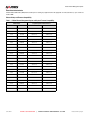
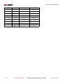
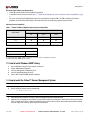
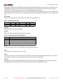
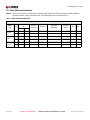
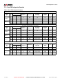
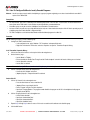
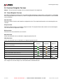
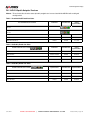
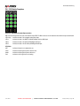
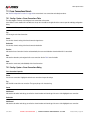
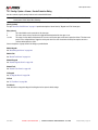
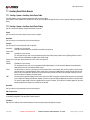
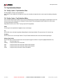
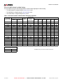
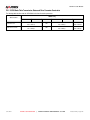
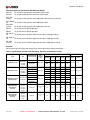
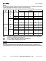
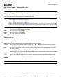
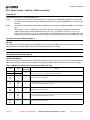
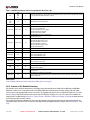
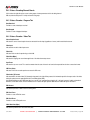
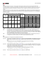
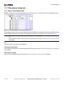
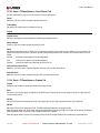
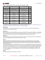
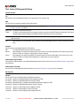
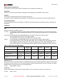
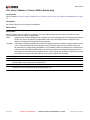
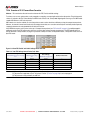
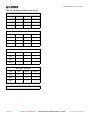
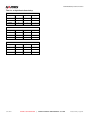
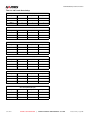
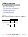
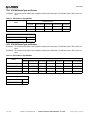
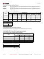
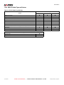
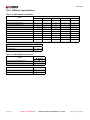
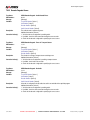
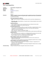
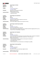
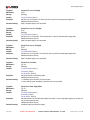
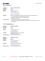
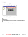
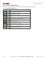
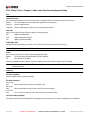
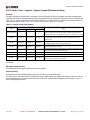
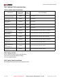
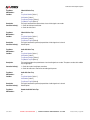
Release History and Firmware Compatibility
Table 1-1 Vidiem Element Management System and System Firmware Compatibility
Vidiem Release
Compatible System Firmware Releases
Release Number
Release Date
NetVX Firmware
FlexiCoder DVS Firmware
6.0.0
06-28-12
8.6.0 to 1.0
4.1.10 to 3.7.0
5.6.0
03-16-12
8.6.0 to 1.0
4.1.10 to 3.7.0
5.3.0
12-11-09
8.3.0 to 1.0
4.1.8 to 3.7.0
5.1.0
07-01-09
8.1.0 to 1.0
4.1.8 to 3.7.0
5.0.0
04-10-09
8.0.0 to 1.0
4.1.8 to 3.7.0
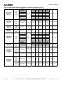
4.8.0
02-06-09
7.8.0 to 1.0
4.1.8 to 3.7.0
4.7.1
12-09-08
7.8.0 to 1.0
4.1.8 to 3.7.0
4.7.0
11-04-08
7.7.0 to 1.0
4.1.8 to 3.7.0
4.6.0
07-29-08
7.6.0 to 1.0
4.1.8 to 3.7.0
4.5.0
04-28-08
7.5.0 to 1.0
4.1.8 to 3.7.0
4.4.0
03-07-08
7.4.0 to 1.0
4.1.8 to 3.7.0
4.3.0
01-09-08
7.3.0 to 1.0
4.1.8 to 3.7.0
4.2.0
09-27-07
7.2.0 to 1.0
4.1.8 to 3.7.0
4.0.0
05-14-07
7.0.0 to 1.0
4.1.8 to 3.7.0
4.0.0
10-03-06
6.7.0 to 1.0
4.1.6 to 3.7.0
3.9.0
05-30-06
6.6.0 to 1.0
4.1.6 to 3.7.0
3.8.0
01-13-06
6.5.1 to 1.0
4.1.6 to 3.7.0
3.7.0
11-04-05
6.5.0 to 1.0
4.1.6 to 3.7.0
3.6.1
08-11-05
6.1.0 to 1.0
4.1.6 to 3.7.0
3.6.0
06-21-05
6.0.0 to 1.0
4.1.6 to 3.7.0
3.5.0
03-30-05
5.8.0 to 1.0
4.1.6 to 3.7.0
3.4.0
02-09-05
5.7.0 to 1.0
4.1.6 to 3.7.0
3.3.0
08-16-04
5.6.0 to 1.0
4.1.2 to 3.7.0
June 2012
HARRI S CO RPO RATI O N
|
V I D I E M E L E ME N T MA N A G E ME N T S Y S T E M
Release 6.0.0 | Page 3
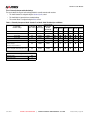
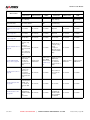
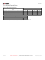
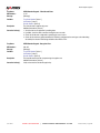
Vidiem Element Management System
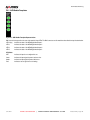
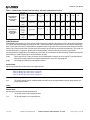
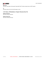
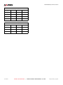
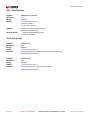
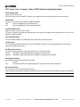
3.2.0
03-22-03
5.5.0 to 1.0
4.1.2 to 3.7.0
3.1.0
12-31-03
5.2.0 to 1.0
4.1.1 to 3.7.0
3.0.0
11-31-03
5.0.0 to 1.0
4.1.0 to 3.7.0
2.3.0
06-09-03
3.1 to 1.0
4.0.1 to 3.7.0
2.2.0
02-11-03
3.0 to 1.0
4.0.1 to 3.7.0
2.1.0
11-15-02
2.0 to 1.0
3.9.2 to 3.7.0
1.3.2
07-16-03
N/A
3.9.2 to 3.7.0
1.3.0
08-28-03
N/A
3.9.0 to 3.7.0
1.2.1
01-24-02
N/A
3.8.1 to 3.7.0
1.2.0
09-06-01
N/A
3.8.0 to 3.7.0
June 2012
HARRI S CO RPO RATI O N
|
V I D I E M E L E ME N T MA N A G E ME N T S Y S T E M
Release 6.0.0 | Page 4
List of Vidiem & NetVX Procedures
TOC
LOF List of Figures ................................................................................................................................................................... 23
Volume 1: Vidiem™ Element Management System .................................................................................................................. 31
1
Getting Started... ............................................................................................................................................................... 33
1.1
1.2
1.3
1.4
1.5
1.6
1.7
1.8
1.9
1.10
1.11
1.12
1.13
June 2012
Installation and Configuration Overview ....................................................................................................................................
Installation Requirements ..........................................................................................................................................................
How to Install Windows SNMP Library ......................................................................................................................................
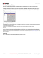
How to Install the Vidiem™ Element Management System.......................................................................................................
How to do a Silent Install of the Vidiem™ Element Management System.................................................................................
How to Start the Vidiem™ Element Management System ........................................................................................................
Vidiem™ User Management Procedures ..................................................................................................................................
1.7.1
Overview of User Profiles and Access Levels.........................................................................................................
1.7.2
How to Add a New User Profile...............................................................................................................................
1.7.3
How to Delete an Existing User Profile ...................................................................................................................
1.7.4
How to Edit a User Profile .......................................................................................................................................
User Management Dialogs ........................................................................................................................................................
1.8.1
Users Dialog............................................................................................................................................................
1.8.2
User Properties Dialog ............................................................................................................................................
1.8.3
Login Dialog ............................................................................................................................................................
FlexiCoder DVS Ethernet IP Address Procedures.....................................................................................................................
1.9.1
How to Set the FlexiCoder DVS Ethernet IP Address.............................................................................................
1.9.2
How to Check the FlexiCoder DVS Ethernet IP Address ........................................................................................
How to Set the NetVX IP Address .............................................................................................................................................
1.10.1
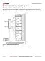
IP Address Configuration Using the Front Panel Interface......................................................................................
1.10.2
IP Address Configuration Using the Craft Port or Telnet Interface..........................................................................
1.10.3
How to Verify the NetVX Ethernet IP Address ........................................................................................................
Vidiem™ Device Management Procedures ...............................................................................................................................
1.11.1
How to Add a Device to the Vidiem™ Device List...................................................................................................
1.11.2
How to Remove a Device from the Device List .......................................................................................................
1.11.3
How to Edit a Device ...............................................................................................................................................
1.11.4
How to Read a Device Configuration ......................................................................................................................
1.11.5
How to Write Settings to a Device...........................................................................................................................
1.11.6
How to Create a Device Configuration File Without a Device .................................................................................
Device Management Dialogs .....................................................................................................................................................
1.12.1
Devices Dialog ........................................................................................................................................................
1.12.2
Device Selection Dialog ..........................................................................................................................................
1.12.3
Device Snapshot Dialog ..........................................................................................................................................
1.12.4
Device Properties > Identification Dialog ................................................................................................................
1.12.5
Device Properties > SNMP Dialog ..........................................................................................................................
1.12.6
Device Properties > Members.................................................................................................................................
How to Access the NetVX Using Telnet.....................................................................................................................................
1.13.1
Prerequisites ...........................................................................................................................................................
1.13.2
Telnet Access Using a Windows PC .......................................................................................................................
1.13.3
Telnet Access Using a UNIX Terminal or Workstation............................................................................................
HARRI S CO RPO RATI O N
|
V I D I E M E L E ME N T MA N A G E ME N T S Y S T E M
33
33
34
34
35
35
35
35
36
36
36
36
36
37
37
37
37
38
38
38
38
39
39
39
40
40
40
41
41
41
41
42
42
42
43
43
43
43
43
44
Release 6.0.0 | Page 5
List of Vidiem & NetVX Procedures
1.14
1.15
1.16
2
1.13.4
If Vidiem™ Can Not Read a Device... .....................................................................................................................
Configuration File Management Procedures .............................................................................................................................
1.14.1
New File Dialog .......................................................................................................................................................
1.14.2
How to Save a System Configuration to a File........................................................................................................
1.14.3
How to Copy System Configurations Between Files and Devices ..........................................................................
Overview of the SNMP Community String .................................................................................................................................
Reference Procedures ...............................................................................................................................................................
1.16.1
How to Connect to a Device Using Windows HyperTerminal .................................................................................
1.16.2
How to Ping a Device ..............................................................................................................................................
44
44
44
45
45
45
46
46
46
Vidiem™ Overview ............................................................................................................................................................ 49
2.1
2.2
2.3
2.4
2.5
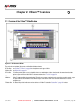
Overview of the Vidiem™ Main Window....................................................................................................................................
2.1.1
Vidiem™ Title Bars..................................................................................................................................................
2.1.2
Menu Bar.................................................................................................................................................................
2.1.3
Vidiem™ Document Windows.................................................................................................................................
2.1.4
Tool Bar...................................................................................................................................................................
2.1.5
Status Bar................................................................................................................................................................
Preferences Dialogs...................................................................................................................................................................
2.2.1
Tools > Preferences > Default SNMP Communication Values Dialog ....................................................................
2.2.2
Tools > Preferences > File Properties for Trap Logging Dialog ..............................................................................
Overview of BISS Scrambling....................................................................................................................................................
BISS Scrambling Dialogs...........................................................................................................................................................
2.4.1
Tools > BISS Keys Dialog .......................................................................................................................................
2.4.2
Tools > BISS Keys > New (button) > BISS Descrambler Dialog.............................................................................
2.4.3
Tools > Carousel > Carousel Builder ......................................................................................................................
2.4.4
Tools > Carousel > Carousel Loader ......................................................................................................................
Vidiem™ Trap Log and SNMP Communication.........................................................................................................................
2.5.1
Trap Log Dialog.......................................................................................................................................................
2.5.2
Trap Log Filter Dialog..............................................................................................................................................
2.5.3
Help > About Vidiem™............................................................................................................................................
2.5.4
Vidiem™ > References ...........................................................................................................................................
49
50
51
53
54
54
55
55
55
56
56
56
57
58
58
58
58
59
59
60
Volume 2: NetVX Video Networking System .............................................................................................................................. 61
3
NetVX Configuration Procedures .................................................................................................................................... 63
3.1
3.2
3.3
3.4
June 2012
Introduction ................................................................................................................................................................................
Basic Configuration Procedures ................................................................................................................................................
3.2.1
How to Add a Module to a System Configuration....................................................................................................
3.2.2
How to Encode Material Using MPEG-2 .................................................................................................................
3.2.3
How to Decode MPEG-2 Material ...........................................................................................................................
ENC: Closed Captions and Related Procedures .......................................................................................................................
3.3.1
Overview of NetVX Closed Caption Inputs..............................................................................................................
3.3.2
Overview of NetVX Closed Caption Protocol ..........................................................................................................
3.3.3
How to Use UDP to Insert Closed Captions Into an MPEG-2 Program ..................................................................
3.3.4
How to Insert Closed Captions Into an MPEG-2 Program Using VBI .....................................................................
ENC: VANC, Embedded Data and Splice Point-Related Procedures .......................................................................................
3.4.1
How to Configure HD Encoder Vertical Ancillary Data (VANC) Services................................................................
3.4.2
How to Filter Data Channels From a Program Stream............................................................................................
3.4.3
How to Configure an Encoder to Receive GPI-Triggered Splice Points..................................................................
3.4.4
How To Configure an Encoder to Receive IP-Triggered Splice Points ...................................................................
HARRI S CO RPO RATI O N
|
V I D I E M E L E ME N T MA N A G E ME N T S Y S T E M
63
64
64
64
65
66
66
66
68
69
70
70
71
71
72
Release 6.0.0 | Page 6
List of Vidiem & NetVX Procedures
3.5
3.6
3.7
3.8
3.9
3.10
3.11
3.12
3.13
June 2012
AUD: Associated and Standalone Audio Configuration Procedures..........................................................................................
3.5.1
Overview of AUD-D14 Associated Audio ................................................................................................................
3.5.2
How to Configure a Standalone Audio Encoding Channel......................................................................................
3.5.3
How to Configure a Standalone Audio Decoding Channel......................................................................................
3.5.4
How to Associate Audio Channels with an Encoding Program ...............................................................................
3.5.5
How to Decode Associated Audio Channels...........................................................................................................
3.5.6
How to Filter Audio Channels From a Program Stream ..........................................................................................
ATM: Video Over ATM Procedures ...........................................................................................................................................
3.6.1
How to Send Video Over an ATM Connection ........................................................................................................
3.6.2
How to Receive Video from an ATM Connection ....................................................................................................
GBE/ATM: IP on ATM Procedures ............................................................................................................................................
3.7.1
How to Configure IP on ATM Networks (Generalized)............................................................................................
3.7.2
Blank IPOA Network Worksheet .............................................................................................................................
3.7.3
How to Configure the NetVX to Support IP on ATM Bridging .................................................................................
3.7.4
IP on ATM Configuration Worksheet.......................................................................................................................
3.7.5
How to Configure an IPOA Ring Network ...............................................................................................................
3.7.6
IPOA Ring Network Worksheet ...............................................................................................................................
3.7.7
Overview of NetVX Inverse ATM ARP Functionality ...............................................................................................
TMX: ASI and 310M Mux Demux Procedures ...........................................................................................................................
3.8.1
How to Route an ASI or 310M Input to a Demux VC (Pass Through) ....................................................................
3.8.2
How to Demultiplex an ASI or 310M MPTS ............................................................................................................
3.8.3
How to Demultiplex an Internal MPTS ....................................................................................................................
3.8.4
How to Loopback ASI or 310M Input.......................................................................................................................
3.8.5
How to Route an Internal Transport Stream to an ASI or 310M Output (Pass Through) ........................................
3.8.6
How to Multiplex VCs into an MPTS for Tx Output .................................................................................................
3.8.7
Telnet PasswordHow to Multiplex VCs into an MPTS for Internal Use ...................................................................
TMX: Statistical Multiplexing Procedures...................................................................................................................................
3.9.1
Overview of NetVX Statistical Multiplexing..............................................................................................................
3.9.2
Overview of the StatMux Priority Control ................................................................................................................
3.9.3
Overview of Methods for NetVX StatMux................................................................................................................
3.9.4
How To Configure StatMux for Locally-Encoded Programs....................................................................................
3.9.5
How To Configure StatMux For Distributed Programs Received over ASI .............................................................
3.9.6
How To Configure StatMux For Distributed Programs Received over GBE ...........................................................
3.9.7
How To Configure StatMux For Distributed Programs Received over ATM ...........................................................
3.9.8
How to Configure Default PID Values .....................................................................................................................
3.9.9
How to Manually Map VC PID Values on a Mux Interface ......................................................................................
3.9.10
How to Configure the NetVX to Use Conditional Access ........................................................................................
3.9.11
How to Add BISS Conditional Access to a Transport Stream .................................................................................
3.9.12
How to Drop Conditional Access from a Program Stream ......................................................................................
TMX: Opportunistic Data Overview and Procedure ...................................................................................................................
3.10.1
Overview of Opportunistic Data...............................................................................................................................
3.10.2
How to Configure Opportunistic Data Insertion .......................................................................................................
TMX: PSIP and Data Carousel Procedures...............................................................................................................................
3.11.1
How to Use the Carousel Builder to Create Carousel Files ....................................................................................
3.11.2
How to Use the Carousel Loader to Load Carousel Files .......................................................................................
3.11.3
How to Multiplex PSIP Data into a Transport Stream .............................................................................................
3.11.4
How to Configure Carousel Directories and Files ...................................................................................................
3.11.5
How to Enable the Data Carousel for Operation .....................................................................................................
TMX: ISDB-Tb-Related Procedures...........................................................................................................................................
3.12.1
How to Configure the TMX to Support ISDB-Tb......................................................................................................
3.12.2
How to Add Entries to the ISDB-Tb Event Table.....................................................................................................
TMX: Mobile/Handheld (M/H) Procedures .................................................................................................................................
3.13.1
How to Configure Mobile/Handheld (M/H) on an ATSC Broadcast Configuration ..................................................
HARRI S CO RPO RATI O N
|
V I D I E M E L E ME N T MA N A G E ME N T S Y S T E M
73
73
75
76
77
79
81
82
82
82
83
83
84
85
87
88
89
90
91
91
92
93
94
95
97
99
100
100
101
103
104
106
109
112
114
115
116
118
118
119
119
120
122
122
122
124
125
127
128
128
131
132
132
Release 6.0.0 | Page 7
List of Vidiem & NetVX Procedures
3.14
3.15
3.16
3.17
3.18
3.19
3.20
3.21
3.22
3.23
June 2012
VC: Virtual Channel Procedures ................................................................................................................................................
3.14.1
How to Create an ATM Virtual Channel ..................................................................................................................
3.14.2
How to Create a ‘Copy’ ATM Virtual Channel .........................................................................................................
3.14.3
How to Create an IP Virtual Channel ......................................................................................................................
3.14.4
How to Configure an IP VC for VLAN Support ........................................................................................................
3.14.5
How Configure an IP VC to Receive a Source-Specific Multicast...........................................................................
3.14.6
How to Configure an IP VC to Transmit a Source-Specific Multicast......................................................................
3.14.7
How to Modify a Virtual Channel .............................................................................................................................
3.14.8
How to Delete a Virtual Channel .............................................................................................................................
3.14.9
How to Route ATM Traffic According to VPI ...........................................................................................................
Cross Connection Procedures ...................................................................................................................................................
3.15.1
How to Create a Cross Connection.........................................................................................................................
3.15.2
How to Configure a Backup Cross Connection .......................................................................................................
3.15.3
How to Modify a Cross Connection .........................................................................................................................
3.15.4
How to Delete a Cross Connection .........................................................................................................................
GBE & SYS: IP Module Procedures ..........................................................................................................................................
3.16.1
How to Manually Configure the IP Routing Table ...................................................................................................
3.16.2
How to Carry LAN Traffic over a Transport Stream Connection (IP on TS)............................................................
GBE & SYS: LAN Extension and VLAN Procedures .................................................................................................................
3.17.1
How to Configure VLAN and LAN Extension ..........................................................................................................
3.17.2
How to Link VLANs Over ATM ................................................................................................................................
NetVX System Configuration Procedures..................................................................................................................................
3.18.1
Overview of NetVX System Configurations.............................................................................................................
3.18.2
How to Save a NetVX System Configuration ..........................................................................................................
3.18.3
How to Simultaneously Save Several NetVX System Configurations (Snapshot Feature).....................................
3.18.4
How to Load a NetVX System Configuration ..........................................................................................................
3.18.5
How to Delete a NetVX System Configuration ........................................................................................................
Module Profile Management Procedures...................................................................................................................................
3.19.1
Overview of Module Profiles....................................................................................................................................
3.19.2
How to Save a Profile from a Branch ......................................................................................................................
3.19.3
How to List All Encoder and Decoder Profiles.........................................................................................................
3.19.4
How to Load a Profile into a Branch........................................................................................................................
3.19.5
How to Delete a Profile............................................................................................................................................
Status Monitoring Procedures....................................................................................................................................................
3.20.1
How to Monitor NetVX Status..................................................................................................................................
3.20.2
How to Save Status Parameters to a File ...............................................................................................................
3.20.3
How to Clear Module Status and Counter Values...................................................................................................
Trap Log Procedures .................................................................................................................................................................
3.21.1
How to View the Vidiem™ Trap Log .......................................................................................................................
3.21.2
How to Save Trap Log Entries to a File...................................................................................................................
3.21.3
How to Acknowledge All Traps in the ‘Current Log’ Display ...................................................................................
3.21.4
How to Delete Traps from the ‘History Log’ Display................................................................................................
How to Configure Modules for BISS Scrambling and Descrambling .........................................................................................
3.22.1
How to Configure Encoders for BISS Scrambling ...................................................................................................
3.22.2
How to Configure a TMX Transmit Stream for BISS Scrambling ............................................................................
3.22.3
How to Configure Decoders for BISS Descrambling...............................................................................................
3.22.4
How to Use the BISS Keys Dialog to View Encrypted Session Words ...................................................................
System Branch Procedures .......................................................................................................................................................
3.23.1
How to Set the Network Time Server IP Address ...................................................................................................
3.23.2
How to Configure the Logical IP Subnet (LIS) Table Entries ..................................................................................
3.23.3
How to Enable Router Information Protocol (RIP)...................................................................................................
HARRI S CO RPO RATI O N
|
V I D I E M E L E ME N T MA N A G E ME N T S Y S T E M
136
136
138
139
140
141
142
143
144
145
146
146
147
148
149
150
150
151
152
152
154
155
155
155
155
157
157
158
158
158
158
158
159
160
160
160
160
161
161
161
161
161
162
162
163
164
165
166
166
166
167
Release 6.0.0 | Page 8
List of Vidiem & NetVX Procedures
3.24
3.25
3.26
3.27
3.28
3.29
4
Overview ....................................................................................................................................................................................
NetVX Navigation Tree ..............................................................................................................................................................
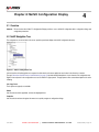
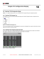
Overview of the Configuration Display.......................................................................................................................................
Configuration Table Display.......................................................................................................................................................
Overview of NetVX Interfaces and Addressing..........................................................................................................................
Overview of Navigation Tree Icons ............................................................................................................................................
4.6.1
General Navigation Tree Icons................................................................................................................................
4.6.2
AUD-D14-Specific Navigation Tree Icons ...............................................................................................................
177
177
178
178
179
180
180
181
NetVX Virtual Channels & Cross Connections ............................................................................................................... 183
5.1
5.2
6
168
168
168
169
169
169
170
170
170
171
171
171
172
172
173
174
174
175
NetVX Configuration Display ........................................................................................................................................... 177
4.1
4.2
4.3
4.4
4.5
4.6
5
Additional Serial Port Configuration Procedures........................................................................................................................
3.24.1
How to Use Telnet to Communicate with a Serial Port ...........................................................................................
3.24.2
How to Use UDP to Communicate with a Serial Port..............................................................................................
Key Configuration Procedures ...................................................................................................................................................
3.25.1
How to Set the System Chassis Key.......................................................................................................................
3.25.2
How to Set a Module Key........................................................................................................................................
System Password Procedures...................................................................................................................................................
3.26.1
The Default Telnet Password ..................................................................................................................................
3.26.2
How to Change the NetVX System Password ........................................................................................................
System and Module Reset Procedures .....................................................................................................................................
3.27.1
How to Reset the System........................................................................................................................................
3.27.2
How to Reset Individual Modules ............................................................................................................................
System Date and Time Procedures ...........................................................................................................................................
3.28.1
How to Change the System Date and Time ............................................................................................................
3.28.2
How to Configure the NetVX for Daylight Saving Time Transitions ........................................................................
Miscellaneous ............................................................................................................................................................................
3.29.1
General Principles of Operation ..............................................................................................................................
3.29.2
Windows Event Viewer............................................................................................................................................
Overview of Virtual Channels.....................................................................................................................................................
5.1.1
Encoders and Decoders Operate Like Virtual Channels.........................................................................................
5.1.2
System Controller Virtual Channels ........................................................................................................................
5.1.3
GBE-C11 Network Interface Virtual Channels ........................................................................................................
5.1.4
ATM-x11 Network Interface Virtual Channels .........................................................................................................
5.1.5
TMX-M12 Transport Stream Virtual Channels ........................................................................................................
Overview of Cross Connections.................................................................................................................................................
183
183
183
184
184
184
185
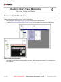
NetVX Status Monitoring .................................................................................................................................................. 187
6.1
6.2
6.3
6.4
June 2012
Overview of NetVX Status Monitoring........................................................................................................................................
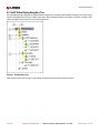
NetVX Status Display Navigation Tree ......................................................................................................................................
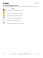
NetVX Status Navigation Tree Icons .........................................................................................................................................
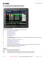
Overview of the NetVX Status Display in Vidiem.......................................................................................................................
6.4.1
Fan Icons.................................................................................................................................................................
HARRI S CO RPO RATI O N
|
V I D I E M E L E ME N T MA N A G E ME N T S Y S T E M
187
188
189
190
191
Release 6.0.0 | Page 9
List of Vidiem & NetVX Procedures
6.5
6.6
7
Overview of Slot Redundancy Labels ........................................................................................................................................
Module Status Images ...............................................................................................................................................................
6.6.1
ATM Module Faceplates .........................................................................................................................................
6.6.2
ENC-Module Faceplates .........................................................................................................................................
6.6.3
AUD-Module Faceplates .........................................................................................................................................
6.6.4
ENC-Module Faceplates .........................................................................................................................................
6.6.5
DEC-S11 Faceplates...............................................................................................................................................
6.6.6
SYS-A12 SYS-A22 Faceplates ...............................................................................................................................
6.6.7
TMX-M12 Faceplate................................................................................................................................................
6.6.8
TMX-M14 Faceplate................................................................................................................................................
6.6.9
GBE-C11 Faceplate ................................................................................................................................................
6.6.10
Power Module Faceplate.........................................................................................................................................
6.6.11
GPI/GPO State........................................................................................................................................................
6.6.12
System Controller Data Ports..................................................................................................................................
6.6.13
NetVX Module State Icons ......................................................................................................................................
192
193
193
194
195
196
197
197
198
199
200
200
200
200
201
NetVX System Branch ...................................................................................................................................................... 203
7.1
7.2
7.3
7.4
7.5
7.6
7.7
7.8
June 2012
System Branch...........................................................................................................................................................................
7.1.1
Config > System > Fundamentals Tab....................................................................................................................
7.1.2
Config > System > Fundamentals Dialog................................................................................................................
7.1.3
Config > System > Fundamentals > Network Dialog ..............................................................................................
7.1.4
Config > System > Fundamentals > Program Dialog..............................................................................................
7.1.5
Config > System > Fundamentals > Daylight Saving Time Dialog..........................................................................
7.1.6
Config > System > Controls Dialog .........................................................................................................................
Cross Connections Branch ........................................................................................................................................................
7.2.1
Config > System > Cross Connections Table .........................................................................................................
7.2.2
Config > System > Cross Connections Dialog ........................................................................................................
Alarms Branch ...........................................................................................................................................................................
7.3.1
Overview of NetVX Alarms......................................................................................................................................
7.3.2
Config > System > Alarms Table.............................................................................................................................
7.3.3
Config > System > General Alarms Dialog..............................................................................................................
7.3.4
Config > System > Alarms > Coding Alarms Dialog................................................................................................
7.3.5
Config > System > Alarms > Service Protection Dialog ..........................................................................................
GPI Contacts Branch .................................................................................................................................................................
7.4.1
GPI Contacts Overview ...........................................................................................................................................
7.4.2
Config > System > GPI Contacts Table ..................................................................................................................
7.4.3
Config > System > GPI Contacts Dialog .................................................................................................................
GPO Relays Branch...................................................................................................................................................................
7.5.1
GPO Relays Overview ............................................................................................................................................
7.5.2
Config > System > GPO Relays Table....................................................................................................................
7.5.3
Config > System > GPO Relays Dialog...................................................................................................................
Logical IP Subnets Branch.........................................................................................................................................................
7.6.1
Config > System > Logical IP Subnet Table............................................................................................................
7.6.2
Config > System > Logical IP Subnets Dialog.........................................................................................................
Auxiliary Serial Ports Branch .....................................................................................................................................................
7.7.1
Config > System > Auxiliary Serial Ports Table.......................................................................................................
7.7.2
Config > System > Auxiliary Serial Ports Dialog .....................................................................................................
Trap Destinations Branch ..........................................................................................................................................................
7.8.1
Config > System > Trap Destinations Table............................................................................................................
7.8.2
Config > System > Trap Destinations Dialog ..........................................................................................................
HARRI S CO RPO RATI O N
|
V I D I E M E L E ME N T MA N A G E ME N T S Y S T E M
203
203
205
207
208
209
210
212
212
212
214
214
215
215
216
217
218
218
218
218
219
219
219
219
221
221
221
222
222
222
224
224
224
Release 6.0.0 | Page 10
List of Vidiem & NetVX Procedures
7.9
7.10
7.11
7.12
7.13
8
NetVX Modules Branch ..................................................................................................................................................... 237
8.1
8.2
9
Config > System > CA Scrambling Control Groups Branch....................................................................................................... 225
7.9.1
Config > System > CA Scrambling Control Groups > CA SCG # Branch ............................................................... 225
7.9.2
Config > System > CA Scrambling Control Groups > CA SCG # > CA SCG Tab .................................................. 225
7.9.3
Config > System > CA Scrambling Control Groups > CA SCG # > ECM Tab ........................................................ 225
Config > System > CA Properties Dialogs ................................................................................................................................. 225
7.10.1
Config > System > CA SCGs (or) CA Systems > CA SCG # > CA Properties > CA SCG Dialog .......................... 225
7.10.2
Config > System > CA SCGs (or) CA Systems > CA SCG # > CA Properties > CA SCG > ECM Dialog .............. 226
7.10.3
Config > System > CA SCGs (or) CA Systems > CA SCG # > CA Properties > CA System Dialog ...................... 227
7.10.4
Config > System > CA SCGs (or) CA Systems > CA SCG # > CA Properties > CA System > Access Criteria Dialog
227
7.10.5
Config > System > CA SCGs (or) CA Systems > CA SCG # > CA Properties > CA System > ECMG Dialog ....... 228
7.10.6
Config > System > CA SCGs (or) CA Systems > CA SCG # > CA Properties > CA System > EMMG Dialog....... 228
Config > System > CA Systems Branch .................................................................................................................................... 230
7.11.1
Config > System > CA Systems > CA System # > ECM Generators > CA System Tab......................................... 230
7.11.2
Config > System > CA Systems > CA System # > ECM Generators > ECMG Tab................................................ 230
7.11.3
Config > System > CA Systems > CA System # > ECM Generators > EMMG Tab ............................................... 230
System Status Branch ............................................................................................................................................................... 232
7.12.1
Status > System > General Tab .............................................................................................................................. 232
7.12.2
Status > System > GPI Tab..................................................................................................................................... 232
7.12.3
Status > System > GPO Tab................................................................................................................................... 233
7.12.4
Status > System > Mechanical Tab......................................................................................................................... 233
7.12.5
Status > System > Serial Tab.................................................................................................................................. 233
7.12.6
Status > System > CA SCG .................................................................................................................................... 234
7.12.7
Status > System > ECM .......................................................................................................................................... 234
7.12.8
Status > System > CA System ................................................................................................................................ 234
7.12.9
Status > System > ECMG ....................................................................................................................................... 234
7.12.10
Status > System > EMMG....................................................................................................................................... 235
Alarms Status Branch ................................................................................................................................................................ 236
7.13.1
Status > Alarms > Current Tab................................................................................................................................ 236
7.13.2
Status > Alarms > History Tab ................................................................................................................................ 236
Module Configuration Tables and Dialogs .................................................................................................................................
8.1.1
Config > Modules Table ..........................................................................................................................................
8.1.2
Config > Module Properties Dialog .........................................................................................................................
Module Status ............................................................................................................................................................................
8.2.1
Status > Modules Table ..........................................................................................................................................
237
237
238
239
239
NetVX Encoder Module ..................................................................................................................................................... 241
9.1
9.2
June 2012
Encoder Configuration ...............................................................................................................................................................
9.1.1
Config > Encoders Table.........................................................................................................................................
Encoding Branch........................................................................................................................................................................
9.2.1
Config > Encoder > Program Tab ...........................................................................................................................
9.2.2
Config > Encoder > Video Tab ................................................................................................................................
9.2.3
Config > Encoder > Audio Tab ................................................................................................................................
9.2.4
Config > Encoder > Control Tab..............................................................................................................................
9.2.5
Config > Encoder > Events Tab ..............................................................................................................................
9.2.6
Config > Encoder > VANC Data Tab.......................................................................................................................
9.2.7
Config > Encoder > VBI Lines Tab..........................................................................................................................
9.2.8
Config > Encoder > VBI Teletext Tab......................................................................................................................
HARRI S CO RPO RATI O N
|
V I D I E M E L E ME N T MA N A G E ME N T S Y S T E M
241
241
242
242
244
245
255
255
256
256
256
Release 6.0.0 | Page 11
List of Vidiem & NetVX Procedures
9.3
9.4
10
Encoder Dialogs.........................................................................................................................................................................
9.3.1
Config > Encoder > Program Dialog .......................................................................................................................
9.3.2
SI/PSI Mode Table Transmission Rates and Other Parameter Constraints ...........................................................
9.3.3
Config > Encoder > Program > Scrambling Dialog .................................................................................................
9.3.4
Config > Encoder > Program > Services Dialog .....................................................................................................
9.3.5
Config > Encoder > Video Dialog ............................................................................................................................
9.3.6
Config > Encoder > Video > Video Picture Dialog ..................................................................................................
9.3.7
Config > Encoder > Video > Video Control Dialog ..................................................................................................
9.3.8
Config > Encoder > Audio Properties Dialog...........................................................................................................
9.3.9
Config > Encoder > Audio Properties > Advanced Dialog ......................................................................................
9.3.10
Config > Encoder > Audio Properties > Advanced AAC Dialog ..............................................................................
9.3.11
Config > Encoder > Video > Audio Channel Dialog ................................................................................................
9.3.12
Config > Encoder > Events Dialog ..........................................................................................................................
9.3.13
Config > Encoder > Events > Event Content Dialog ...............................................................................................
9.3.14
Config > Encoder > VANC Data Dialog...................................................................................................................
9.3.15
Config > Encoder > VANC Data > VANC Services Dialog......................................................................................
9.3.16
Overview of KLV Metadata Processing...................................................................................................................
9.3.17
Config > Encoder > VBI Lines Dialog......................................................................................................................
9.3.18
Config > Encoder > VBI Teletext Dialog..................................................................................................................
Encoder Status ..........................................................................................................................................................................
9.4.1
Status > Encoders Table.........................................................................................................................................
9.4.2
Status > Encoding Channel Branch ........................................................................................................................
9.4.3
Status > Encoder > Program Tab............................................................................................................................
9.4.4
Status > Encoder > Video Tab ................................................................................................................................
9.4.5
Status > Encoder > Audio Tab ................................................................................................................................
9.4.6
Status > Encoder > Splice Log Tab.........................................................................................................................
9.4.7
Status > Encoder > VANC Data Tab.......................................................................................................................
9.4.8
Status > Encoder > VBI Lines Tab ..........................................................................................................................
257
257
259
261
262
265
270
274
275
278
279
281
282
282
283
285
286
288
291
292
292
293
293
293
294
295
295
295
NetVX Decoder Module ..................................................................................................................................................... 297
10.1
10.2
10.3
10.4
June 2012
Decoder Configuration ...............................................................................................................................................................
10.1.1
Config > Decoders Table ........................................................................................................................................
Decoding Channel Branch .........................................................................................................................................................
10.2.1
Config > Decoder > Program Tab ...........................................................................................................................
10.2.2
Config > Decoder > Video Tab................................................................................................................................
10.2.3
Config > Decoder > Audio Tab................................................................................................................................
10.2.4
Config > Decoder > Control Tab .............................................................................................................................
10.2.5
Config > Decoder > VBI Lines Tab..........................................................................................................................
Decoder Dialogs ........................................................................................................................................................................
10.3.1
Config > Decoder > Program Dialog .......................................................................................................................
10.3.2
Config > Decoder > Program > Control Monitoring Dialog......................................................................................
10.3.3
Config > Decoder > Program > Descrambling Dialog .............................................................................................
10.3.4
Config > Decoder > Program > Descrambling Injected Identifier Dialog.................................................................
10.3.5
Config > Decoder > Video Dialog............................................................................................................................
10.3.6
Config > Decoder > Audio Properties Dialog ..........................................................................................................
10.3.7
Config > Decoder > VBI Lines Dialog......................................................................................................................
Decoder Status ..........................................................................................................................................................................
10.4.1
Status > Decoders Table.........................................................................................................................................
10.4.2
Status > Decoding Channel Branch ........................................................................................................................
10.4.3
Status > Decoder > Program Tab ...........................................................................................................................
10.4.4
Status > Decoder > Video Tab ................................................................................................................................
10.4.5
Status > Decoder > Audio Tab ................................................................................................................................
10.4.6
Status > Decoder > VBI Lines Tab..........................................................................................................................
HARRI S CO RPO RATI O N
|
V I D I E M E L E ME N T MA N A G E ME N T S Y S T E M
297
297
298
298
298
299
300
300
301
301
301
302
303
304
306
307
308
308
308
308
309
309
309
Release 6.0.0 | Page 12
List of Vidiem & NetVX Procedures
11
NetVX TMX Module ........................................................................................................................................................... 311
11.1
TS Receivers Configuration .......................................................................................................................................................
11.1.1
Config > TS Receivers Table ..................................................................................................................................
11.2 TS Receivers Branch .................................................................................................................................................................
11.2.1
Config > TS Receivers > Interface Tab ...................................................................................................................
11.2.2
Config > TS Receivers > Demultiplexer VC Tab .....................................................................................................
11.3 TS Receivers Dialogs ................................................................................................................................................................
11.3.1
Config > TS Receivers > Interface Dialog ...............................................................................................................
11.3.2
Config > TS Receivers > VC Control Dialog ...........................................................................................................
11.4 TS Receiver Status ....................................................................................................................................................................
11.4.1
Status > TS Receivers Table ..................................................................................................................................
11.4.2
Status > TS Receivers > Interface Tab ...................................................................................................................
11.4.3
Status > TS Receivers > Virtual Channel Tab.........................................................................................................
11.4.4
Status > TS Receivers > Program Tab ...................................................................................................................
11.4.5
Status > TS Receivers > Program> Elementary Stream Tab .................................................................................
11.5 TS Transmitter Configuration.....................................................................................................................................................
11.5.1
Config > TS Transmitters Table ..............................................................................................................................
11.6 TS Transmitter Branch...............................................................................................................................................................
11.6.1
Config > TS Transmitter > Interface Tab.................................................................................................................
11.6.2
Config > TS Transmitter > Multiplexer VC Tab .......................................................................................................
11.6.3
Config > TS Transmitter > Interface Dialog.............................................................................................................
11.6.4
Config > TS Transmitter > Demultiplexer VC Tab...................................................................................................
11.6.5
Config > TS Transmitter > Interface > Transport Stream Dialog.............................................................................
11.6.6
Config > TS Transmitter > Interface > Transport Stream, Network Dialog .............................................................
11.6.7
Config > TS Transmitter > Interface > Cable Delivery System Dialog ....................................................................
11.6.8
Config > TS Transmitter > Interface > Satellite Delivery System Dialog.................................................................
11.6.9
Config > TS Transmitter > Interface > Terrestrial Delivery System Dialog..............................................................
11.6.10
Config > TS Transmitter > Interface > ISDB-Tb Modulation Dialog ........................................................................
11.6.11
Config > TS Transmitter > Interface > ISDB-Tb Hierarchies Dialog........................................................................
11.6.12
Config > TS Transmitter > Interface > ISDB-Tb Localization Dialog.......................................................................
11.6.13
Config > TS Transmitter > Interface > ISDB, Time Dialog ......................................................................................
11.6.14
Config > TS Transmitter > Interface > PmtRef Table..............................................................................................
11.6.15
Config > TS Rx and Tx > Router Dialog..................................................................................................................
11.7 TS Transmitter > VC Control Branch .........................................................................................................................................
11.7.1
Config > TS Transmitter > VC Control Dialog .........................................................................................................
11.7.2
Config > TS Transmitter > VC Control > Program, ISDB Dialog.............................................................................
11.7.3
Config > TS Transmitter > VC Control > M/H Ensemble Dialog .............................................................................
11.7.4
Config > TS Transmitter > VC Control > Program, Scrambling Dialog ...................................................................
11.7.5
Config > TS Transmitter > VC Control > Opportunistic Data Dialog .......................................................................
11.8 TS Transmitter Status ................................................................................................................................................................
11.8.1
Status > TS Transmitters Table ..............................................................................................................................
11.8.2
Status > TS Transmitters > Interface Tab ...............................................................................................................
11.8.3
Status > TS Transmitters > Demultiplexer VC Tab .................................................................................................
11.8.4
Status > TS Transmitters > Program Tab ...............................................................................................................
11.8.5
Status > TS Transmitters > Program > Elementary Stream Tab ............................................................................
11.9 TS Demultiplexer Configuration .................................................................................................................................................
11.9.1
Config > TS Demultiplexers Table ..........................................................................................................................
11.9.2
Config > TS Demultiplexers > Interface Tab ...........................................................................................................
11.9.3
Config > TS Demultiplexers > Virtual Channel Tab.................................................................................................
11.10 Config TS Demultiplexer Dialog.................................................................................................................................................
11.10.1
Config > TS Demultiplexers > Interface Dialog .......................................................................................................
June 2012
HARRI S CO RPO RATI O N
|
V I D I E M E L E ME N T MA N A G E ME N T S Y S T E M
311
311
313
313
314
315
315
317
318
318
318
319
319
320
321
321
322
322
322
322
326
328
330
331
332
333
334
334
335
336
336
337
338
338
340
341
343
344
345
345
345
347
347
348
349
349
350
351
352
352
Release 6.0.0 | Page 13
List of Vidiem & NetVX Procedures
11.11 Config > TS Demultipexers > VC Control Branch......................................................................................................................
11.11.1
Config > TS Demultiplexers > VC Control Dialog....................................................................................................
11.11.2
Config > TS Demultiplexers > VC Control Dialog > Program, Audio Filter Dialog ..................................................
11.11.3
Config > TS Demultiplexers > VC Control Dialog > Program, Data Filter Dialog....................................................
11.12 TS Demultiplexer Status ............................................................................................................................................................
11.12.1
Status > TS Demultiplexers Table...........................................................................................................................
11.12.2
Status > TS Demultiplexers > Interface Tab ...........................................................................................................
11.12.3
Status > TS Demultiplexers > Virtual Channel Tab.................................................................................................
11.12.4
Status > TS Demultiplexers > Program Tab............................................................................................................
11.12.5
Status > TS Demultiplexers > Program> Elementary Stream Tab..........................................................................
11.13 TS Multiplexer Configuration......................................................................................................................................................
11.13.1
Config > TS Multiplexers Table ...............................................................................................................................
11.14 TS Multiplexer Branch................................................................................................................................................................
11.14.1
Config > TS Multiplexers > Interface Tab................................................................................................................
11.14.2
Config > TS Multiplexers > Virtual Channel Tab .....................................................................................................
11.15 TS Multiplexer Dialogs ...............................................................................................................................................................
11.15.1
Config > TS Multiplexers > Interface Dialog............................................................................................................
11.16 Config > TS Multiplexers > VC Control Branch..........................................................................................................................
11.16.1
Config > TS Multiplexers > VC Control Dialog ........................................................................................................
11.16.2
Config > TS Multiplexers > VC Control > Program, Details Dialog .........................................................................
11.16.3
Config > TS Multiplexers > VC Control > Program, Statmux Dialog .......................................................................
11.16.4
Config > TS Multiplexers > VC Control > Program, PID Mapping Dialog ...............................................................
11.16.5
Config > TS Multiplexers > VC Control > PID Insertion Dialog ...............................................................................
11.16.6
Subtitling Descriptor Dialog .....................................................................................................................................
11.17 Scramblers.................................................................................................................................................................................
11.17.1
Config > Scramblers > SCR Properties Dialog .......................................................................................................
11.18 TS Multiplexer Status.................................................................................................................................................................
11.18.1
Status > TS Multiplexers Table ...............................................................................................................................
11.18.2
Status > TS Multiplexers > Interface Tab ................................................................................................................
11.18.3
Status > TS Multiplexers > Multiplexer VC Tab.......................................................................................................
11.18.4
Status > TS Multiplexers > Program Tab ................................................................................................................
11.18.5
Status > TS Multiplexers > Program > Elementary Stream Tab .............................................................................
12
353
353
355
355
356
356
356
357
357
358
359
359
360
360
361
362
362
363
363
364
366
368
371
372
373
373
374
374
376
378
379
379
NetVX ATM Modules ......................................................................................................................................................... 381
12.1
12.2
12.3
12.4
12.5
June 2012
Overview of NetVX ATM Interfaces ...........................................................................................................................................
12.1.1
About NetVX ATM Interfaces ..................................................................................................................................
12.1.2
ATM Interface Configuration Parameters................................................................................................................
Overview of NetVX ATM Interface Rates...................................................................................................................................
ATM Configuration .....................................................................................................................................................................
12.3.1
Config > ATM Interfaces Table ...............................................................................................................................
12.3.2
Config > ATM Interfaces > Interface Tab ................................................................................................................
12.3.3
Config > ATM Interfaces > Virtual Channel Tab......................................................................................................
ATM Configuration Dialogs ........................................................................................................................................................
12.4.1
Config > ATM Properties SONET/SDH Dialog........................................................................................................
12.4.2
Config > ATM Properties PDH Dialog .....................................................................................................................
12.4.3
Config > ATM Interface > Router Dialog .................................................................................................................
Config > ATM Interface > VC Control Branch............................................................................................................................
12.5.1
Config > ATM Interface > VC Control Dialog ..........................................................................................................
12.5.2
Config > ATM Interface > VC Control > VC Processing Dialog ..............................................................................
12.5.3
Config > ATM Interface > VC Control > VC Rates Dialog.......................................................................................
HARRI S CO RPO RATI O N
|
V I D I E M E L E ME N T MA N A G E ME N T S Y S T E M
381
381
381
382
383
383
384
384
384
384
387
388
389
389
392
394
Release 6.0.0 | Page 14
List of Vidiem & NetVX Procedures
12.6
13
395
395
396
398
401
NetVX IP Module ................................................................................................................................................................ 403
13.1
13.2
13.3
13.4
13.5
13.6
14
ATM Status ................................................................................................................................................................................
12.6.1
Status > ATM Interfaces Summary Table ...............................................................................................................
12.6.2
Status > ATM Interfaces > SONET/SDH Interface Tab ..........................................................................................
12.6.3
Status > ATM Interfaces > PDH Interface Tab........................................................................................................
12.6.4
Status > ATM Interfaces > Virtual Channel Tab......................................................................................................
IP Module Configuration ............................................................................................................................................................
13.1.1
Config > IP Modules Table......................................................................................................................................
IP Module Branch ......................................................................................................................................................................
13.2.1
Config > IP Modules > Interface Tab.......................................................................................................................
13.2.2
Config > IP Modules > IP Routing Table Tab..........................................................................................................
13.2.3
Config > IP Modules > Virtual Channel Tab ............................................................................................................
13.2.4
Config > IP Modules > Auxiliary Tab .......................................................................................................................
13.2.5
Config > IP Modules > VLAN Tab ...........................................................................................................................
13.2.6
Config > IP Modules > DHCP Tab ..........................................................................................................................
13.2.7
Config > IP Modules > M/H Services Tab ...............................................................................................................
IP Module Configuration Dialogs ...............................................................................................................................................
13.3.1
Config > IP Modules > Slot#.Interface Dialog .........................................................................................................
13.3.2
Config > IP Modules > IP Routing Table Dialog......................................................................................................
13.3.3
Config > IP Modules > M/H Services ......................................................................................................................
Config > IP Modules > VLAN Dialog..........................................................................................................................................
Config > IP Modules > VC Control Branch ................................................................................................................................
13.5.1
Config > IP Modules > VC Control Dialog ...............................................................................................................
13.5.2
Config > IP Modules > VC Control > Network Dialog..............................................................................................
13.5.3
Config > IP Modules > VC Control > MPEG Rx, Multicast Dialog...........................................................................
13.5.4
Config > IP Modules > VC Control > MPEG Rx Dialog...........................................................................................
13.5.5
Config > IP Modules > VC Control > MPEG Tx, Network Dialog ............................................................................
13.5.6
Config > IP Modules > VC Control > MPEG Tx, Stream Dialog..............................................................................
13.5.7
Overview of VC ‘Function’ and ‘IP Address’ Setting Dependencies........................................................................
13.5.8
Overview of IP VC Forward Error Correction ..........................................................................................................
13.5.9
Config > IP Modules > DHCP Dialog ......................................................................................................................
IP Module Status........................................................................................................................................................................
13.6.1
Status > IP Modules Table ......................................................................................................................................
13.6.2
Status > IP Modules > Interface Tab.......................................................................................................................
13.6.3
Status > IP Modules > IP Routing Table Tab ..........................................................................................................
13.6.4
Status > IP Modules > Virtual Channel Tab ............................................................................................................
403
403
404
404
404
404
404
404
404
404
405
405
407
408
409
409
409
411
413
414
415
417
419
420
421
422
422
422
425
426
NetVX Redundancy & Service Protection ....................................................................................................................... 429
14.1
14.2
14.3
14.4
June 2012
Overview ....................................................................................................................................................................................
General Module Redundancy Procedures.................................................................................................................................
14.2.1
Overview of Backup Module Compatibility ..............................................................................................................
14.2.2
How to Configure a Main Module ............................................................................................................................
14.2.3
How to Configure a Backup Module........................................................................................................................
14.2.4
How to Configure Distributed Redundant Encoders................................................................................................
14.2.5
How to Identify a Module Failover ...........................................................................................................................
14.2.6
How to Cause a Service to Failover ........................................................................................................................
14.2.7
How to Cause a Service to Failback .......................................................................................................................
Overview of NetVX Multiple-Module Redundancy .....................................................................................................................
Overview of Network Module Redundancy................................................................................................................................
14.4.1
ATM Path Protection: Using Redundant ATM Modules ..........................................................................................
14.4.2
ATM Path Protection: Using an External Optical Switch .........................................................................................
14.4.3
IP Path Protection: Using Redundant IP Modules...................................................................................................
HARRI S CO RPO RATI O N
|
V I D I E M E L E ME N T MA N A G E ME N T S Y S T E M
429
431
431
432
434
435
438
439
440
441
443
443
444
445
Release 6.0.0 | Page 15
List of Vidiem & NetVX Procedures
14.5
14.6
14.7
14.8
Overview of Cross Connection Redundancy .............................................................................................................................
System Controller Redundancy Wiring and Configuration.........................................................................................................
Receive Interface Router Settings .............................................................................................................................................
Receive Interface Redundancy Wiring and Configurations .......................................................................................................
14.8.1
Using an NxN Router with Encoder Module Receive Interfaces .............................................................................
14.8.2
Using an 8x1 Digital Router with Encoder Module Receive Interfaces ...................................................................
14.8.3
Using an 8x1 Analog Router with Encoder Module Receive Interfaces ..................................................................
14.9 Transmit Interface Router Settings ............................................................................................................................................
14.10 Transmit Interface Redundancy Wiring and Configurations ......................................................................................................
14.10.1
Using a NxN Digital or Analog Router with Module Transmit Interfaces .................................................................
15
NetVX Utilities .................................................................................................................................................................... 461
15.1
15.2
15.3
16
446
448
450
451
451
454
456
458
459
459
Utilities Branch ...........................................................................................................................................................................
15.1.1
Config > Utilities > Configuration Tab......................................................................................................................
15.1.2
Config > Utilities > Firmware Tab ............................................................................................................................
15.1.3
Config > Utilities > Profile Tab.................................................................................................................................
Utility Dialogs .............................................................................................................................................................................
15.2.1
Config > Utilities > Clear Status Dialog ...................................................................................................................
15.2.2
Config > Utilities > Configuration Dialog..................................................................................................................
15.2.3
Config > Utilities > Firmware Dialog ........................................................................................................................
15.2.4
Config > Utilities > Key Dialog.................................................................................................................................
15.2.5
Config > Utilities > Profile Dialog.............................................................................................................................
15.2.6
Config > Utilities > Protection Modules Dialog ........................................................................................................
15.2.7
Config > Utilities > Protection Services Dialog ........................................................................................................
15.2.8
Config > Utilities > Reset Dialog..............................................................................................................................
15.2.9
Config > Utilities > Set Time Dialog.........................................................................................................................
System and Module Types and Keyed Features .......................................................................................................................
15.3.1
SYS-200 Chassis Types and Features ...................................................................................................................
15.3.2
SYS-300 Chassis Types and Features ...................................................................................................................
15.3.3
SYS-350 Chassis Types and Features ...................................................................................................................
15.3.4
SYS-1700 Chassis Types and Features .................................................................................................................
15.3.5
System Controller Module Types and Features ......................................................................................................
15.3.6
ATM-M11 ATM-S11 and ATM-L11 Module Types and Features............................................................................
15.3.7
ATM-X11 Module Types and Features ...................................................................................................................
15.3.8
ENC-S11 Module Types and Features ...................................................................................................................
15.3.9
ENC-S21 Module Types and Features ...................................................................................................................
15.3.10
ENC-H11 Module Types and Features ...................................................................................................................
15.3.11
ENC-A11 Module Types and Features ...................................................................................................................
15.3.12
ENC-A21 Module Types and Features ...................................................................................................................
15.3.13
AUD-D14 Module Types and Features ...................................................................................................................
15.3.14
DEC Module Types and Features ...........................................................................................................................
15.3.15
TMX Module Types and Features ...........................................................................................................................
15.3.16
GBE Module Types and Features ...........................................................................................................................
461
461
461
462
463
463
464
465
466
467
468
469
470
471
472
472
473
473
474
474
474
475
476
477
478
478
479
480
480
481
482
NetVX Trap Descriptions .................................................................................................................................................. 483
16.1
June 2012
Overview of NetVX Traps and Alarms ....................................................................................................................................... 483
16.1.1
Coding Alarms......................................................................................................................................................... 483
16.1.2
General Alarms ....................................................................................................................................................... 483
HARRI S CO RPO RATI O N
|
V I D I E M E L E ME N T MA N A G E ME N T S Y S T E M
Release 6.0.0 | Page 16
List of Vidiem & NetVX Procedures
16.2
16.3
17
Trap and Alarm Types ...............................................................................................................................................................
16.2.1
Audio Degrade Alarms ............................................................................................................................................
16.2.2
Audio Fault Alarm....................................................................................................................................................
16.2.3
Decoder Degrade Alarms........................................................................................................................................
16.2.4
Module Degrade Alarms..........................................................................................................................................
16.2.5
Module Fault Alarms ...............................................................................................................................................
16.2.6
Network Degrade Alarms ........................................................................................................................................
16.2.7
Network Fault Alarms ..............................................................................................................................................
16.2.8
Service Degrade Alarms .........................................................................................................................................
16.2.9
Service Fault Alarm .................................................................................................................................................
16.2.10
System Degrade Alarm ...........................................................................................................................................
16.2.11
System Fault Alarms ...............................................................................................................................................
16.2.12
VANC Degrade Alarm .............................................................................................................................................
16.2.13
VBI Degrade Alarm .................................................................................................................................................
16.2.14
VC Degrade Alarms ................................................................................................................................................
16.2.15
VC Fault Alarm ........................................................................................................................................................
16.2.16
Video Degrade Alarms ............................................................................................................................................
16.2.17
Video Fault Alarm....................................................................................................................................................
16.2.18
Start Up Traps .........................................................................................................................................................
NetVX Trap Variable Definitions ................................................................................................................................................
16.3.1
Trap Count Number.................................................................................................................................................
16.3.2
Slot Number ............................................................................................................................................................
16.3.3
From: Slot Number ..................................................................................................................................................
16.3.4
To: Slot Number ......................................................................................................................................................
16.3.5
From Slot State: ......................................................................................................................................................
16.3.6
To Slot State:...........................................................................................................................................................
16.3.7
Reset Description ....................................................................................................................................................
16.3.8
Encoder Number .....................................................................................................................................................
16.3.9
Decoder Number .....................................................................................................................................................
16.3.10
Audio Channel Number ...........................................................................................................................................
16.3.11
Virtual Channel Number ..........................................................................................................................................
16.3.12
Virtual Channel Type...............................................................................................................................................
16.3.13
Cross Connection Number ......................................................................................................................................
16.3.14
Fan Number ............................................................................................................................................................
16.3.15
Interface Number.....................................................................................................................................................
16.3.16
Serial Port Number..................................................................................................................................................
16.3.17
GPO Number...........................................................................................................................................................
16.3.18
Power Supply ..........................................................................................................................................................
484
484
485
486
489
492
493
495
496
497
498
501
503
503
504
509
509
510
510
511
511
511
511
511
511
511
511
511
511
511
511
512
512
512
512
512
512
512
NetVX Bandwidth .............................................................................................................................................................. 513
17.1
June 2012
NetVX Backplane Bandwidth Considerations ............................................................................................................................ 513
HARRI S CO RPO RATI O N
|
V I D I E M E L E ME N T MA N A G E ME N T S Y S T E M
Release 6.0.0 | Page 17
List of Vidiem & NetVX Procedures
17.2
17.3
17.4
17.5
NetVX Module Bandwidth Usage...............................................................................................................................................
Range of NetVX Encoder Rates ................................................................................................................................................
Overview of the Program Transport Stream Rate......................................................................................................................
17.4.1
Program and System Information............................................................................................................................
17.4.2
Separate PID...........................................................................................................................................................
17.4.3
Frame Completion...................................................................................................................................................
17.4.4
4:2:2 Coding ............................................................................................................................................................
17.4.5
Audio Rate...............................................................................................................................................................
17.4.6
VBI lines ..................................................................................................................................................................
17.4.7
Vertical Ancillary Data .............................................................................................................................................
17.4.8
Safety Factor ...........................................................................................................................................................
17.4.9
Transport Stream Overhead....................................................................................................................................
17.4.10
Video Rate...............................................................................................................................................................
17.4.11
StatMux and the Transport Stream Rate.................................................................................................................
ATM Standards and Rate Calculations......................................................................................................................................
514
515
516
516
517
517
517
517
517
517
517
518
518
518
519
Volume 3: FlexiCoder™ Digital Video System ........................................................................................................................... 521
18
Configuration Display ....................................................................................................................................................... 523
18.1
19
523
523
523
524
524
FlexiCoder™ DVS Status Monitoring .............................................................................................................................. 525
19.1
19.2
19.3
19.4
19.5
20
FlexiCoder™ DVS Configuration Display ..................................................................................................................................
18.1.1
FlexiCoder™ DVS Navigation Tree.........................................................................................................................
18.1.2
FlexiCoder™ DVS Composite Configuration Display..............................................................................................
18.1.3
FlexiCoder™ DVS Module State Icons ...................................................................................................................
18.1.4
FlexiCoder™ DVS Configuration Tables.................................................................................................................
Overview of FlexiCoder™ DVS Status Monitoring.....................................................................................................................
Status Monitoring Procedures....................................................................................................................................................
19.2.1
How to Monitor FlexiCoder™ DVS Status...............................................................................................................
19.2.2
How to Save Status Parameters to a File ...............................................................................................................
FlexiCoder™ DVS Status Display Details..................................................................................................................................
19.3.1
FlexiCoder™ DVS Status Navigation Tree .............................................................................................................
19.3.2
FlexiCoder™ DVS Status Navigation Tree Icons....................................................................................................
19.3.3
FlexiCoder™ DVS Status Display ...........................................................................................................................
19.3.4
FlexiCoder™ DVS Module State Icons ...................................................................................................................
Status > Modules .......................................................................................................................................................................
19.4.1
Main Module Type...................................................................................................................................................
19.4.2
Main Module State ..................................................................................................................................................
19.4.3
Alarm State..............................................................................................................................................................
Status > System.........................................................................................................................................................................
19.5.1
Status > System > Summary Tab ...........................................................................................................................
19.5.2
Status > System > PDH Tab ...................................................................................................................................
19.5.3
Status > System > SONET/SDH Tab......................................................................................................................
525
526
526
526
527
527
527
528
529
530
530
530
530
532
532
533
534
FlexiCoder™ DVS Alarms ................................................................................................................................................ 537
20.1
June 2012
Overview of FlexiCoder™ DVS Alarms .....................................................................................................................................
20.1.1
Overview of Alarm Thresholds ................................................................................................................................
20.1.2
Overview of Alarm Severity .....................................................................................................................................
20.1.3
Overview of Alarm Persistence ...............................................................................................................................
HARRI S CO RPO RATI O N
|
V I D I E M E L E ME N T MA N A G E ME N T S Y S T E M
537
537
537
538
Release 6.0.0 | Page 18
List of Vidiem & NetVX Procedures
20.2
21
21.2
22.2
22.3
543
543
543
543
544
544
545
546
547
548
549
549
550
551
553
554
554
555
557
558
559
560
Decoder Module Procedures .....................................................................................................................................................
22.1.1
How to Create a FlexiCoder™ DVS Decoding Session ..........................................................................................
22.1.2
How to Delete a FlexiCoder™ DVS Decoding Session ..........................................................................................
Decoder Configuration Dialogs ..................................................................................................................................................
22.2.1
Config > Decoding > Decoder Input Properties Dialog ...........................................................................................
22.2.2
Config > Decoding > Decoder Audio Properties Dialog ..........................................................................................
22.2.3
Config > Decoding > Decoder Video Properties Dialog ..........................................................................................
22.2.4
Config > Decoding > Decoder Video Router Properties Dialog ..............................................................................
Decoding Configuration Tables..................................................................................................................................................
22.3.1
Decoders Table .......................................................................................................................................................
561
561
561
562
562
563
564
565
566
566
FlexiCoder™ DVS Mini Master Control Module .............................................................................................................. 569
23.1
23.2
24
Encoder Procedures ..................................................................................................................................................................
21.1.1
How to Create a FlexiCoder™ DVS Encoding Session ..........................................................................................
21.1.2
How to Add an Associated FlexiCoder™ DVS Audio Channel to an Encoding Session ........................................
21.1.3
How to Delete a FlexiCoder™ DVS Encoding Session...........................................................................................
Encoder Module Configuration ..................................................................................................................................................
21.2.1
Config > Trunk # > Program # > Video > Video Properties Dialog..........................................................................
21.2.2
Config > Trunk # > Program # > Video > Input Video Processing Properties Dialog..............................................
21.2.3
Config > Trunk # > Program # > Video > MPEG-2 Video Processing Properties Dialog ........................................
21.2.4
Config > Trunk # > Program # > Video > MPEG-2 Structure Properties Dialog .....................................................
21.2.5
Config > Trunk # > Program # > Teletext/Data Properties Dialog...........................................................................
21.2.6
Config > Trunk # > Program # > Teletext/Data >Teletext Lines Dialog...................................................................
21.2.7
Config > Trunk # > Program # > Serial # > Serial Properties Dialog.......................................................................
21.2.8
Config > Trunk # > Program # > Serial # > Serial Application Properties ...............................................................
21.2.9
Config > Trunk # > Program # > Program > Program Output Properties................................................................
21.2.10
Config > Trunk # > Program # > Program > Program PID Assignments Dialog .....................................................
21.2.11
Config > Trunk # > Program # > Program > Program Routing Properties Dialog ...................................................
21.2.12
Config > Trunk # > Program # > Program > Program Setups Dialog......................................................................
21.2.13
Config > Trunk # > Program # > Audio Properties Dialog.......................................................................................
21.2.14
Config > Trunk # > Program # > Audio Bitstream Information Dialog .....................................................................
21.2.15
Config > Trunk # > Program # > Audio Internal/External Encoding Dialog .............................................................
21.2.16
Config > Trunk # > Program # > Audio Preprocessing Properties Dialog...............................................................
21.2.17
Config > Trunk # > Program # > Audio Service Properties Dialog..........................................................................
FlexiCoder™ DVS Decoder Modules ............................................................................................................................... 561
22.1
23
539
539
539
541
542
FlexiCoder™ DVS Encoder Module ................................................................................................................................. 543
21.1
22
Alarm Configuration Dialogs ......................................................................................................................................................
20.2.1
Config > System > Alarm Persistence.....................................................................................................................
20.2.2
Config > System > Alarms > Equipment Error Thresholds .....................................................................................
20.2.3
Config > System > Alarms > Link Error Thresholds ................................................................................................
20.2.4
Config > System > Alarms > Module Errors............................................................................................................
Master Control Dialogs ..............................................................................................................................................................
23.1.1
Config > Master Control Video Properties Dialog ...................................................................................................
23.1.2
Config > Master Control SD and HD Audio Dialog..................................................................................................
Master Control Table .................................................................................................................................................................
569
569
570
571
FlexiCoder™ DVS Transport Stream Importer Module .................................................................................................. 573
24.1
24.2
June 2012
Overview of FlexiCoder™ DVS TSI-100 Services .....................................................................................................................
TSI Configuration Procedures....................................................................................................................................................
24.2.1
How to Create a FlexiCoder™ DVS TSI-100 Service .............................................................................................
24.2.2
How to Use the TSI Service Wizard ........................................................................................................................
HARRI S CO RPO RATI O N
|
V I D I E M E L E ME N T MA N A G E ME N T S Y S T E M
573
573
573
573
Release 6.0.0 | Page 19
List of Vidiem & NetVX Procedures
25
FlexiCoder™ DVS Trunk Configuration .......................................................................................................................... 575
25.1
25.2
25.3
26
26.2
26.3
26.4
26.5
26.6
IP Network Configuration ...........................................................................................................................................................
26.1.1
Config > System > Network > IP Network Interface Properties ..............................................................................
26.1.2
Config > System > Network > IP Services Properties.............................................................................................
Video Network Configuration .....................................................................................................................................................
26.2.1
Config > System > Network > Video Network Properties........................................................................................
ATM Network Configuration.......................................................................................................................................................
26.3.1
Config > System > Network > Video Network > ATM Network Properties..............................................................
26.3.2
Overview of the FlexiCoder™ DVS ATM Routing Table .........................................................................................
ATM Routing Table Procedures.................................................................................................................................................
26.4.1
How to Add One or More ATM Routing Table Entries ............................................................................................
26.4.2
How to Highlight a Range of ATM Routing Table Cells...........................................................................................
26.4.3
How to Edit FlexiCoder™ DVS ATM Routing Table Entries ...................................................................................
Video Transport Stream Network Configuration ........................................................................................................................
26.5.1
Config > System > Network > Video Network > Transport Stream Network Properties .........................................
26.5.2
FlexiCoder™ DVS Interface Data Rates .................................................................................................................
26.5.3
Config > Set Time ...................................................................................................................................................
26.5.4
Config > Reset System Alarms ...............................................................................................................................
26.5.5
Config > System > Slot # Module Properties ..........................................................................................................
ASI I/O Module Procedures .......................................................................................................................................................
26.6.1
How to Create an ASI Encoding Session................................................................................................................
26.6.2
How to Create a FlexiCoder™ DVS ASI Decoding Session ...................................................................................
585
585
586
587
587
588
588
589
590
590
590
590
591
591
592
592
592
593
594
594
594
FlexiCoder™ DVS Module Redundancy ......................................................................................................................... 595
27.1
27.2
28
575
575
576
577
577
577
577
579
580
580
581
582
582
582
583
FlexiCoder™ DVS Network Configuration ...................................................................................................................... 585
26.1
27
StatMux Configuration Procedures ............................................................................................................................................
25.1.1
How to Create a Statmux Group .............................................................................................................................
25.1.2
How to Optimize GOP-Structure Frame Spacing for StatMuxed Programs............................................................
Trunk Configuration ...................................................................................................................................................................
25.2.1
Config > Trunk # > Trunk Properties Dialog............................................................................................................
25.2.2
Config > Trunk # > Load New File Into Data Carousel Dialog ................................................................................
25.2.3
Config > Trunk # > StatMux Properties Dialog........................................................................................................
25.2.4
Config > Trunk # > StatMux > Program # Dialog ....................................................................................................
25.2.5
Config > Trunk # > Transport Stream Input Properties Dialog ................................................................................
25.2.6
Config > Trunk # > Transport Stream Setups .........................................................................................................
25.2.7
Config > Trunk # > Program # > Service # Properties Dialog .................................................................................
Network Output Branch..............................................................................................................................................................
25.3.1
Network Output > Bandwidth Tab ...........................................................................................................................
25.3.2
Network Output > Routing Summary Tab ...............................................................................................................
25.3.3
Network Output > Trunk > Trunk Tab......................................................................................................................
Overview of FlexiCoder™ DVS Module Redundancy................................................................................................................
FlexiCoder™ DVS Module Redundancy Procedures ................................................................................................................
27.2.1
How to Assign a FlexiCoder™ DVS Module to a Backup Group ............................................................................
27.2.2
How to Configure a FlexiCoder™ DVS Module to Serve as a Backup Module ......................................................
27.2.3
How to Recover a FlexiCoder™ DVS NIM from a Failover.....................................................................................
27.2.4
How to Recover a FlexiCoder™ DVS E ..................................................................................................................
27.2.5
How to Transfer Service Between Like Modules.....................................................................................................
595
595
595
595
596
596
596
FlexiCoder™ DVS Utility Operations ............................................................................................................................... 597
28.1
June 2012
FlexiCoder™ DVS System and Module Reset .......................................................................................................................... 597
28.1.1
How to Reset the FlexiCoder™ DVS System ......................................................................................................... 597
28.1.2
How to Reset FlexiCoder™ DVS Modules.............................................................................................................. 597
HARRI S CO RPO RATI O N
|
V I D I E M E L E ME N T MA N A G E ME N T S Y S T E M
Release 6.0.0 | Page 20
List of Vidiem & NetVX Procedures
28.2
29
FlexiCoder™ DVS Program Setups...........................................................................................................................................
28.2.1
Overview of Program Setups ..................................................................................................................................
28.2.2
How to Add an Encoding Program to a Setup.........................................................................................................
28.2.3
How to Add NIM-IO-ASI Input to a Setup................................................................................................................
28.2.4
Config > System > System Fundamentals Dialog...................................................................................................
28.2.5
Config > System > System Fundamentals > Feature Authorization Dialog ............................................................
598
598
598
598
599
599
FlexiCoder™ DVS Trap Descriptions .............................................................................................................................. 601
29.1
29.2
29.3
Overview of FlexiCoder™ DVS Traps .......................................................................................................................................
FlexiCoder™ DVS Trap Variable Definitions .............................................................................................................................
29.2.1
Trap Count Number.................................................................................................................................................
29.2.2
Trap Event Code .....................................................................................................................................................
29.2.3
Module Type............................................................................................................................................................
29.2.4
Slot Number ............................................................................................................................................................
29.2.5
Trap Channel Number.............................................................................................................................................
29.2.6
Trap To Slot Number...............................................................................................................................................
29.2.7
Trap ATM Network Type .........................................................................................................................................
29.2.8
Trap Cleared Trap Counter .....................................................................................................................................
29.2.9
Trap IP Address ......................................................................................................................................................
29.2.10
Trap Time Delta.......................................................................................................................................................
29.2.11
Trap Module Trap ID ...............................................................................................................................................
29.2.12
Trap Cleared Trap ID ..............................................................................................................................................
29.2.13
Trap Port Number....................................................................................................................................................
Trap and Alarm Types ...............................................................................................................................................................
601
601
601
601
601
602
602
602
602
602
602
602
602
602
602
603
Volume 4: Appendices ................................................................................................................................................................. 619
30
Selenio Status Monitoring ................................................................................................................................................ 621
30.1
30.2
30.3
30.4
30.5
A
621
621
622
623
623
628
Appendix A: Release Notes ............................................................................................................................................. 629
A.1
B
Overview of Selenio Status Monitoring ......................................................................................................................................
Configuring a Selenio Device for Status Display in Vidiem........................................................................................................
Status Display Navigation Tree..................................................................................................................................................
Status Navigation Tree Icons.....................................................................................................................................................
Overview of the Selenio Status Display in Vidiem .....................................................................................................................
30.5.1
Selenio Traps ..........................................................................................................................................................
Known Issues.............................................................................................................................................................................
A.1.1
Vidiem™ 2.3.1 Help System ...................................................................................................................................
A.1.2
Issue Regarding the LDV EMS 1.2.0 Uninstaller ....................................................................................................
A.1.3
vnet011179 - PDH and SONET System Errors.......................................................................................................
A.1.4
vnet010731 - Mode Switching TS to ATM; or ATM to TS .......................................................................................
A.1.5
vnet011179 - Erroneous ATM Output Errors and Counts .......................................................................................
629
629
629
630
630
630
Appendix B: NetVX Firmware Upgrade Procedure ........................................................................................................ 631
B.1
B.2
B.3
B.4
B.5
B.6
B.7
June 2012
Purpose......................................................................................................................................................................................
Step I: Clear Space and Use Upgrade.exe to Copy New Firmware ..........................................................................................
Step II: Using Vidiem – Activate the New Firmware on the System Controller..........................................................................
Step III: Using Vidiem – Final Upgrade Steps for Dual-System Controller Systems .................................................................
Step II: Using the Craft Port – Activate the New Firmware ........................................................................................................
Step III: Using the Craft Port – Final Upgrade Steps for Dual-System Controller Systems .......................................................
How to Change the Current Active Firmware ............................................................................................................................
HARRI S CO RPO RATI O N
|
V I D I E M E L E ME N T MA N A G E ME N T S Y S T E M
631
632
634
635
637
637
638
Release 6.0.0 | Page 21
List of Vidiem & NetVX Procedures
June 2012
HARRI S CO RPO RATI O N
|
V I D I E M E L E ME N T MA N A G E ME N T S Y S T E M
Release 6.0.0 | Page 22
LOF
List of Figures
LOF
List of Figures.......................................................................................................................................................................................... 23
1
Getting Started... .....................................................................................................................................................................................
Figure 1-1
Vidiem™ Devices Dialog ..................................................................................................................................................
Figure 1-2
Vidiem™ Device Properties Dialog ..................................................................................................................................
Figure 1-3
Windows ‘Run’ dialog Box ................................................................................................................................................
Figure 1-4
Ping Command.................................................................................................................................................................
Figure 1-5
Successful (left) and Unsuccessful (right) Attempts to Ping a Device..............................................................................
33
39
40
47
47
47
2
Vidiem™ Overview ..................................................................................................................................................................................
Figure 2-1
Main Document Window...................................................................................................................................................
Figure 2-2
Main Application Window Title Bar ...................................................................................................................................
Figure 2-3
Device Document in Window Title Bar .............................................................................................................................
Figure 2-4
Unsaved Configuration File in Document Window Title Bar.............................................................................................
Figure 2-5
Configuration File in Document Window Title Bar ............................................................................................................
Figure 2-6
Device and Saved Configuration in Document Window ...................................................................................................
Figure 2-7
Status Display in Document Window................................................................................................................................
Figure 2-8
Vidiem™ Menu Bar ..........................................................................................................................................................
Figure 2-9
A Typical Vidiem™ Dialog ................................................................................................................................................
Figure 2-10 Vidiem™ Tool Bar ............................................................................................................................................................
Figure 2-11 Vidiem™ Status Bar .........................................................................................................................................................
49
49
50
50
50
50
50
51
51
53
54
54
3
NetVX Configuration Procedures .......................................................................................................................................................... 63
Figure 3-1
AUD-D14 Audio Encode and Decode Modes of Operation.............................................................................................. 73
Figure 3-2
AUD-D14 Performing Mixed Modes of Operation ............................................................................................................ 74
Figure 3-3
Four Channels of Audio Associated with One Encoder.................................................................................................... 77
Figure 3-4
Decoding Four Channels of Associated Audio ................................................................................................................. 79
Figure 3-5
IPOA Bridging Topology ................................................................................................................................................... 85
Figure 3-6
IPOA Ring Network Topology........................................................................................................................................... 88
Figure 3-7
Receiving an External MPTS to Passthrough .................................................................................................................. 91
Figure 3-8
Receiving an External MPTS to Demux ........................................................................................................................... 92
Figure 3-9
Demuxing an Internal MPTS ............................................................................................................................................ 93
Figure 3-10 MPTS Loopback ............................................................................................................................................................... 94
Figure 3-11 Passthrough an Internal MPTS to Transmit ..................................................................................................................... 95
Figure 3-12 Multiplexing Several SPTS to Transmit ............................................................................................................................ 97
Figure 3-13 Multiplexing Several SPTS to Provide Internally to other Modules .................................................................................. 99
Figure 3-14 NetVX StatMux Overview ................................................................................................................................................. 100
Figure 3-15 Multi-Chassis StatMux Configuration Using ASI .............................................................................................................. 106
Figure 3-16 Multi-Chassis StatMux Configuration Using GBE............................................................................................................. 109
Figure 3-17 Multi-Chassis StatMux Configuration Using ATM............................................................................................................. 112
Figure 3-18 NetVX Opportunistic Data Wiring and Connection Configuration..................................................................................... 120
Figure 3-19 ATSC+M/H Configuration................................................................................................................................................. 132
Figure 3-20 Example of the Relationship between a Source and a Copy VC ..................................................................................... 138
Figure 3-21 A NetVX Network Using VLAN and LAN Extension ......................................................................................................... 152
Figure 3-22 NetVX Network Linking Two VLANs Over ATM ............................................................................................................... 154
Figure 3-23 Daylight Saving Transition, Alarm, and Configuration Timeline ....................................................................................... 173
June 2012
HARRI S CO RPO RATI O N
|
V I D I E M E L E ME N T MA N A G E ME N T S Y S T E M
Release 6.0.0 | Page 23
List of Figures
4
NetVX Configuration Display ................................................................................................................................................................. 177
Figure 4-1
Vidiem™ Configuration Tree ............................................................................................................................................ 177
Figure 4-2
NetVX’s Configuration Display ......................................................................................................................................... 178
Figure 4-3
NetVX Configuration Table Display .................................................................................................................................. 178
Figure 4-4
Vidiem™’s Navigation Tree .............................................................................................................................................. 179
5
NetVX Virtual Channels & Cross Connections..................................................................................................................................... 183
Figure 5-1
NetVX Configuration Hierarchy (Overview) ...................................................................................................................... 183
Figure 5-2
NetVX Configuration Hierarchy (Overview) ...................................................................................................................... 185
6
NetVX Status Monitoring ........................................................................................................................................................................ 187
Figure 6-1
NetVX Status Window Displays........................................................................................................................................ 187
Figure 6-2
The NetVX Status Tree .................................................................................................................................................... 188
Figure 6-3
NetVX Status Display ....................................................................................................................................................... 190
Figure 6-4
Vidiem’s Slot Redundancy Labels .................................................................................................................................... 192
Figure 6-5
ATM Module Faceplate Representations ......................................................................................................................... 193
Figure 6-6
ENC-Module Faceplate Representations ......................................................................................................................... 194
Figure 6-7
AUD-Module Faceplate Representations ......................................................................................................................... 195
Figure 6-8
ENC-H11-Module Faceplate Representation ................................................................................................................... 196
Figure 6-9
DEC-S11 Faceplate Representation ................................................................................................................................ 197
Figure 6-10 SYS-A12, and SYS-A22 Faceplate Representations ....................................................................................................... 197
Figure 6-11 TMX-M12 Faceplate Representation................................................................................................................................ 198
Figure 6-12 TMX-M14 Faceplate Representation................................................................................................................................ 199
Figure 6-13 GBE-C11 Faceplate Representation ................................................................................................................................ 200
Figure 6-14 Power Module Representation ......................................................................................................................................... 200
7
NetVX System Branch............................................................................................................................................................................. 203
8
NetVX Modules Branch........................................................................................................................................................................... 237
9
NetVX Encoder Module........................................................................................................................................................................... 241
Figure 9-1
The Encoders Branch of Vidiem™’s Navigation Tree ...................................................................................................... 241
Figure 9-2
Relative Audio Bitrate and Quality Amongst AAC Audio Choices .................................................................................... 248
10
NetVX Decoder Module........................................................................................................................................................................... 297
Figure 10-1 The Decoders Branch of Vidiem™’s Navigation Tree ...................................................................................................... 297
11
NetVX TMX Module.................................................................................................................................................................................. 311
Figure 11-1 The TS Receivers Branch of the Navigation Tree ............................................................................................................ 311
Figure 11-2 The TS Transmitters Branch of the Navigation Tree ........................................................................................................ 321
Figure 11-3 The TS Demultiplexers Branch of the Navigation Tree .................................................................................................... 349
Figure 11-4 The TS Multiplexers Branch of the Navigation Tree......................................................................................................... 359
12
NetVX ATM Modules ............................................................................................................................................................................... 381
Figure 12-1 ATM Interfaces Branch of the Navigation Tree ................................................................................................................ 383
13
NetVX IP Module...................................................................................................................................................................................... 403
Figure 13-1 IP Modules Branch of the Navigation Tree....................................................................................................................... 403
Figure 13-2 How FEC ‘Period’ and ‘Order’ Settings Affect Table Size ................................................................................................ 420
14
NetVX Redundancy & Service Protection ............................................................................................................................................. 429
Figure 14-1 Distributed Redundancy Using Gigabit Ethernet .............................................................................................................. 435
Figure 14-2 Many-to Many Redundancy Configuration ....................................................................................................................... 441
Figure 14-3 ATM Module with Redundant Backup — Normal State.................................................................................................... 443
Figure 14-4 ATM Module with Redundant Backup — Failover State Following A Partial Fiber Break ................................................ 443
Figure 14-5 ATM-S11 and ATM-L11 Redundancy Wiring for the JDS Uniphase LightProtector 530.................................................. 444
Figure 14-6 GBE-C11 Module with Redundant Backup — Normal State............................................................................................ 445
June 2012
HARRI S CO RPO RATI O N
|
V I D I E M E L E ME N T MA N A G E ME N T S Y S T E M
Release 6.0.0 | Page 24
List of Figures
Figure 14-7
Figure 14-8
Figure 14-9
Figure 14-10
Figure 14-11
Figure 14-12
Figure 14-13
GBE-C11 Module with Redundant Backup — Failover State........................................................................................... 445
Example of a Redundant Cross Connection Application.................................................................................................. 446
SYS-A12 Redundancy Wiring .......................................................................................................................................... 448
NxN Digital/Analog Receive Router Wiring ...................................................................................................................... 451
8x1 Digital Router Wiring Configuration ........................................................................................................................... 454
8x1 Analog Router Wiring Configuration .......................................................................................................................... 456
NxN Digital or Analog Router Wiring Configuration.......................................................................................................... 459
15
NetVX Utilities.......................................................................................................................................................................................... 461
16
NetVX Trap Descriptions ........................................................................................................................................................................ 483
17
NetVX Bandwidth .................................................................................................................................................................................... 513
18
Configuration Display ............................................................................................................................................................................. 523
Figure 18-1 FlexiCoder™ DVS Navigation Tree.................................................................................................................................. 523
Figure 18-2 Module Configuration Display........................................................................................................................................... 523
Figure 18-3 A FlexiCoder™ DVS Configuration Table ........................................................................................................................ 524
19
FlexiCoder™ DVS Status Monitoring .................................................................................................................................................... 525
Figure 19-1 FlexiCoder™ DVS Status Window Displays..................................................................................................................... 525
Figure 19-2 The FlexiCoder™ DVS Branch of the Status Tree ........................................................................................................... 527
Figure 19-3 FlexiCoder™ DVS Status Display - WS-5 ........................................................................................................................ 528
20
FlexiCoder™ DVS Alarms....................................................................................................................................................................... 537
Figure 20-1 FlexiCoder™ DVS Alarm Signaling Timeline ................................................................................................................... 537
21
FlexiCoder™ DVS Encoder Module....................................................................................................................................................... 543
22
FlexiCoder™ DVS Decoder Modules..................................................................................................................................................... 561
23
FlexiCoder™ DVS Mini Master Control Module.................................................................................................................................... 569
24
FlexiCoder™ DVS Transport Stream Importer Module........................................................................................................................ 573
25
FlexiCoder™ DVS Trunk Configuration ................................................................................................................................................ 575
26
FlexiCoder™ DVS Network Configuration ............................................................................................................................................ 585
27
FlexiCoder™ DVS Module Redundancy................................................................................................................................................ 595
28
FlexiCoder™ DVS Utility Operations..................................................................................................................................................... 597
29
FlexiCoder™ DVS Trap Descriptions .................................................................................................................................................... 601
30
Selenio Status Monitoring ...................................................................................................................................................................... 621
Figure 30-1 The Selenio Status Tree................................................................................................................................................... 622
Figure 30-2 Selenio Status Display...................................................................................................................................................... 624
A
Appendix A: Release Notes.................................................................................................................................................................... 629
Figure A-1
Recommended Uninstall Procedure for LDV EMS 1.2.0.................................................................................................. 629
B
Appendix B: NetVX Firmware Upgrade Procedure .............................................................................................................................. 631
Figure B-1
Utilities Firmware Dialog................................................................................................................................................... 632
Figure B-2
Upgrade Utility Screen...................................................................................................................................................... 632
Figure B-3
Utilities Firmware Dialog................................................................................................................................................... 634
Figure B-4
Utilities Reset Dialog ........................................................................................................................................................ 635
Figure B-5
Utilities Protection Dialog.................................................................................................................................................. 635
June 2012
HARRI S CO RPO RATI O N
|
V I D I E M E L E ME N T MA N A G E ME N T S Y S T E M
Release 6.0.0 | Page 25
List of Figures
June 2012
HARRI S CO RPO RATI O N
|
V I D I E M E L E ME N T MA N A G E ME N T S Y S T E M
Release 6.0.0 | Page 26
LOT
List of Tables
Table 1-1
Vidiem Element Management System and System Firmware Compatibility...................................................................
3
LOF
List of Figures........................................................................................................................................................................................... 23
1
Getting Started... ...................................................................................................................................................................................... 33
Table 1-1
Vidiem™ SNMP and Windows Operating System Compatibility..................................................................................... 34
Table 1-2
User Access Level and Permitted Vidiem™ Element Management System Activities ................................................... 36
2
Vidiem™ Overview................................................................................................................................................................................... 49
3
NetVX Configuration Procedures .............................................................................................................................................................
Table 3-1
NetVX UDP Frame Format..............................................................................................................................................
‘Protocol’ Byte Values and Their Meaning.......................................................................................................................
Table 3-2
Table 3-3
Blank IPOA Network Worksheet......................................................................................................................................
Table 3-4
IP on ATM Configuration Worksheet .........................................................................................................
Table 3-5
IPOA Ring Network Worksheet .......................................................................................................................................
Table 3-1
External and internal Priority Values ...............................................................................................................................
Table 3-2
StatMux Target Bit Rate Calculation Example ................................................................................................................
Table 3-6
Comparison of Internal and File-System Based Configurations......................................................................................
89
101
102
155
4
NetVX Configuration Display....................................................................................................................................................................
Table 4-1
Associated Audio Encoder Icon States ...........................................................................................................................
Table 4-2
Audio-Only Encoder Icon States .....................................................................................................................................
Table 4-3
Audio-Only Decoder Icon States .....................................................................................................................................
177
181
181
181
5
NetVX Virtual Channels & Cross Connections......................................................................................................................................... 183
6
NetVX Status Monitoring .......................................................................................................................................................................... 187
7
NetVX System Branch.............................................................................................................................................................................. 203
Table 7-1
IP Address Ranges Available for Multicast Addresses.................................................................................................... 211
8
NetVX Modules Branch ............................................................................................................................................................................ 237
9
NetVX Encoder Module............................................................................................................................................................................
Table 9-1
HE-AAC, AAC-LC Audio “Standard” and Audio “Mode” Settings and Bitrates................................................................
Table 9-2
AC-3 Audio “Standard” and Audio “Mode” Relationships and Bitrates............................................................................
Table 9-3
Externally-Compressed Audio “Standard” and Audio “Mode” Relationships and Bitrates...............................................
Table 9-4
MPEG Audio “Standard” and Audio “Mode” Relationships and Bitrates .........................................................................
Table 9-5
SMPTE 302 Sample Size, Bitrate, and Transport Stream Rate ......................................................................................
Table 9-6
Input Resolution, Possible Frame Rate Settings, Standards, and Coded Lines Per Field ..............................................
Table 9-7
Nominal GOP Size Based on ‘Encoder’, ‘Input Signal’, ‘GOP Structure’ and ‘GOP Size’ Setting...................................
Table 9-8
SMPTE 302M Audio Rates as a Function of Sample Size..............................................................................................
Table 9-9
DID/SDID Value Ranges and Passthrough Behavior When Filter is Off .........................................................................
Table 9-10
Active Lines Per Field according to Resolution ...............................................................................................................
Table 9-11
Teletext Descriptor Types Table......................................................................................................................................
10
NetVX Decoder Module............................................................................................................................................................................ 297
Table 10-1
Active Video Lines in NTSC and PAL Formats ............................................................................................................... 304
June 2012
HARRI S CO RPO RATI O N
|
V I D I E M E L E ME N T MA N A G E ME N T S Y S T E M
63
67
67
84
87
241
249
251
252
253
254
266
272
276
285
288
291
Release 6.0.0 | Page 27
List of Tables
11
NetVX TMX Module..................................................................................................................................................................................
Table 11-1
TMX TX Interface ‘Standard’ and ‘Clock’ Setting Dependencies ....................................................................................
Table 11-2
Relationship Between Service Number Options and PMT PID Values for ISDB-Tb Mobile Streams .............................
Table 11-3
VC Descriptor Processing Based on VC Function and Program Number.......................................................................
Table 11-4
Automatic PID Mapping Formula Example Based on ATSC Recommendations............................................................
12
NetVX ATM Modules................................................................................................................................................................................ 381
Table 12-1
Maximum Rates per ATM Interface Type and Standard ................................................................................................. 382
13
NetVX IP Module...................................................................................................................................................................................... 403
Table 13-1
GBE-C11 IP Interface Mode Attributes............................................................................................................................ 406
Table 13-2
How FEC Settings Control ‘Period’ and ‘Order’............................................................................................................... 420
14
NetVX Redundancy & Service Protection ................................................................................................................................................
Table 14-1
NxN Digital/Analog Receive Router Settings...................................................................................................................
Table 14-2
8x1 Digital Receive Router Settings ................................................................................................................................
Table 14-3
4x1 Analog Receive Router Settings...............................................................................................................................
Table 14-4
NxN Transmit Router Settings.........................................................................................................................................
429
452
455
457
460
15
NetVX Utilities ..........................................................................................................................................................................................
Table 15-1
SYS-200 Chassis Type Definitions..................................................................................................................................
Table 15-2
SYS-300 Chassis Type Definitions..................................................................................................................................
Table 15-3
SYS-350 Chassis Type Definitions..................................................................................................................................
Table 15-4
SYS-1700/VR-1700 Chassis Type Definitions ................................................................................................................
Table 15-5
ATM-M11, ATM-S11, and ATM-L11 Module Type Definitions ........................................................................................
Table 15-6
ATM-X11 Module Type Definitions..................................................................................................................................
Table 15-7
ENC-S11 Module Type Definitions..................................................................................................................................
Table 15-8
ENC-S21 Module Type Definitions..................................................................................................................................
Table 15-9
ENC-H11 Module Type Definitions..................................................................................................................................
Table 15-10 ENC-A11 Module Type Definitions..................................................................................................................................
Table 15-11 ENC-A21 Module Type Definitions..................................................................................................................................
Table 15-12 AUD-D14 Module Type Definitions..................................................................................................................................
Table 15-13 DEC-S11 Module Type Definitions..................................................................................................................................
Table 15-14 TMX-M12 Module Type Definitions .................................................................................................................................
Table 15-15 TMX-M14 Module Type Definitions .................................................................................................................................
Table 15-16 GBE-C11 Module Type Definitions..................................................................................................................................
461
472
473
473
474
474
475
476
477
478
478
479
480
480
481
481
482
16
NetVX Trap Descriptions.......................................................................................................................................................................... 483
17
NetVX Bandwidth .....................................................................................................................................................................................
Table 17-1
Parameters Controlling the Rate of Source VC Bandwidth Contribution to the Backplane.............................................
Table 17-2
Module Ingress and Egress Bandwidth ...........................................................................................................................
Table 17-3
Encoder Transport Stream and Video Rate Ranges .......................................................................................................
Table 17-4
Program and System Information Table Rates (SI Bandwidth).......................................................................................
Table 17-5
Maximum ATM Transmits Rates Based on Standard .....................................................................................................
18
Configuration Display ............................................................................................................................................................................... 523
Table 18-1
Vidiem™ Module State Icons .......................................................................................................................................... 524
19
FlexiCoder™ DVS Status Monitoring ....................................................................................................................................................... 525
Table 19-1
WS5 and WS21 Module State Icons ............................................................................................................................... 529
20
FlexiCoder™ DVS Alarms........................................................................................................................................................................ 537
21
FlexiCoder™ DVS Encoder Module......................................................................................................................................................... 543
Table 21-1
Formulas Used for PID Assignments .............................................................................................................................. 553
June 2012
HARRI S CO RPO RATI O N
|
V I D I E M E L E ME N T MA N A G E ME N T S Y S T E M
311
324
340
365
369
513
513
514
515
516
519
Release 6.0.0 | Page 28
List of Tables
22
FlexiCoder™ DVS Decoder Modules....................................................................................................................................................... 561
23
FlexiCoder™ DVS Mini Master Control Module ....................................................................................................................................... 569
24
FlexiCoder™ DVS Transport Stream Importer Module............................................................................................................................ 573
25
FlexiCoder™ DVS Trunk Configuration ................................................................................................................................................... 575
Table 25-1
Recommended Total Rates for 720P and 1080I HD/SD Statmux Programs .................................................................. 575
Table 25-2
Recommended Total Rates for 480P HD/SD Statmux Programs ................................................................................... 575
26
FlexiCoder™ DVS Network Configuration ............................................................................................................................................... 585
Table 26-1
Maximum Trunk and Interface Rates .............................................................................................................................. 592
27
FlexiCoder™ DVS Module Redundancy .................................................................................................................................................. 595
28
FlexiCoder™ DVS Utility Operations........................................................................................................................................................ 597
29
FlexiCoder™ DVS Trap Descriptions....................................................................................................................................................... 601
30
Selenio Status Monitoring ........................................................................................................................................................................ 621
A
Appendix A: Release Notes ..................................................................................................................................................................... 629
B
Appendix B: NetVX Firmware Upgrade Procedure .................................................................................................................................. 631
June 2012
HARRI S CO RPO RATI O N
|
V I D I E M E L E ME N T MA N A G E ME N T S Y S T E M
Release 6.0.0 | Page 29
List of Tables
June 2012
HARRI S CO RPO RATI O N
|
V I D I E M E L E ME N T MA N A G E ME N T S Y S T E M
Release 6.0.0 | Page 30
Volume 1: Vidiem™ Element
Management System
June 2012
HARRI S CO RPO RATI O N
|
V I D I E M E L E ME N T MA N A G E ME N T S Y S T E M
Release 6.0.0 | Page 31
June 2012
HARRI S CO RPO RATI O N
|
V I D I E M E L E ME N T MA N A G E ME N T S Y S T E M
Release 6.0.0 | Page 32
1
Chapter 1: Getting Started...
Installation and Basic Configuration
1.1 Installation and Configuration Overview
This document provides detailed instructions to perform the following basic installation and configuration steps.
1 Install the Vidiem™ Element Management System on your PC. The Vidiem™ Element Management System runs on Windows NT/2000/
XP. An administrative login is required for installation. If you do not have administrative permissions, then ask your system administrator
for help with installation. "How to Install the Vidiem™ Element Management System" on page 34 describes the installation process.
2 Start the Vidiem™ Element Management System.
• See "How to Start the Vidiem™ Element Management System" on page 35.
3 Set, or identify, the IP address of your device. Vidiem™ requires this address to communicate with your device. If you do not know your
system’s IP address, then follow the procedures in the appropriate sections below. TEST
• See "How to Connect to a Device Using Windows HyperTerminal" on page 46.
• See "FlexiCoder DVS Ethernet IP Address Procedures" on page 37.
• See "How to Set the NetVX IP Address" on page 38.
4 Configure the Vidiem™ Element Management System to connect to your device.
• See "How to Add a Device to the Vidiem™ Device List" on page 39.
5 Connect to your device.
• See "How to Read a Device Configuration" on page 40.
1.2 Installation Requirements
Ensure that your PC, network, and NetVX or NetVX (device) meet the following requirements before beginning installation.
Host PC Minimum Requirements
• Windows NT 4.0 with service pack 6 loaded, Windows 2000, WIndows XP.
• 300 MHz Pentium II
• 128 MB ram
• CD-ROM
• 5 GB disk
• Ethernet
• 1024 x 768 display, 16 bits color
• 10/100 BaseT Ethernet Card
Networking Requirements
• 10/100 BaseT Ethernet (IP) connectivity between the PC controller and the device.
NetVX Requirements
• A SYS-G10 controller module must be installed and operational.
• A compatible firmware release as noted in Table 1-1, "Vidiem Element Management System and System Firmware Compatibility" on page
3.
• Be sure to review the NetVX’s Product Release Description (PRD). The PRD is included on the firmware distribution release CD and
provides important, last minute information concerning system operation and performance.
June 2012
HARRI S CO RPO RATI O N
|
V I D I E M E L E ME N T MA N A G E ME N T S Y S T E M
Release 6.0.0 | Page 33
Getting Started...
FlexiCoder Digital Video System Requirements
• A NIM-100 controller module must be installed and operational.
• A compatible firmware release as noted in Table 1-1, "Vidiem Element Management System and System Firmware Compatibility" on page
3.
• Be sure to review the FlexiCoder Digital Video System’s Product Release Description (PRD). The PRD is included on the firmware
distribution release CD and provides important, last minute information concerning system operation and performance.
Operating System Compatibility
Table 1-1 Vidiem™ SNMP and Windows Operating System Compatibility
Windows Operating System
Release Number
NT
XP Service
Pack 1
XP Service
Pack 2
3.4.0 and above
❍
❍
●
3.3.0
●
●
●a
3.2.0 and below
●
❍
●b
Legend
Supported Feature
●
Unsupported Feature
❍
a. Requires Windows’ SNMP ‘Library’ software. See the next section for installation instructions.
b. Requires Windows’ SNMP Library’ software.
1.3 How to Install Windows SNMP Library
1
2
3
4
5
Select ‘Add Remove Programs’ in the windows control panel.
Choose ‘Add Windows Components’.
Check the ‘Management and Monitoring Tools’.
Check the ‘Simple Management Protocol’.
Click on ‘OK’ to install the SNMP windows component.
1.4 How to Install the Vidiem™ Element Management System
Note:
1
2
You must have administrative privileges on your PC to install the Vidiem™ Element Management System.
Close any open programs.
Run the ‘setup.exe’ program from the installation CD.
CD DRIVE:\setup.exe
Note:
3
4
On many systems the setup program will start automatically when the CD is inserted.
Follow the directions provided in the Vidiem™ Element Management System InstallShield wizard.
(Optional) If you are upgrading your installation you may be able to import your existing device entries from the directory in which they
reside. To import device entries, continue the installation until you reach the ‘Select Previous Version Import’ dialog and in that dialog,
select the ‘Import from a Directory’ option and press the ‘Next’ button.
June 2012
HARRI S CO RPO RATI O N
|
V I D I E M E L E ME N T MA N A G E ME N T S Y S T E M
Release 6.0.0 | Page 34
Getting Started...
5
In the ‘Choose Destination Location’ dialog, specify a location such as the following, where #.#.# is the previous version.
C:\Program Files\Harris\Vidiem\#.#.#\Data\
Note:
Special Note for Windows XP Installations:
If the (Windows XP) firewall is enabled, it blocks unsolicited incoming traffic, including SNMP traps. This can be fixed either by turning
off the Windows firewall or by creating an exception, and allowing traffic through UDP port 162.
1.5 How to do a Silent Install of the Vidiem™ Element Management System
Note:
1
2
3
4
5
6
7
You must have administrative privileges on your PC to install the Vidiem™ Element Management System.
Open a command prompt.
Go to the directory that contains the Vidiem setup file.
The following parameters can be used to install silently:
• /S
Silent Install
• /V
Import Version
• /D
Install Location
Type Vidiem-Install-<Version Number>.exe /S /V=<version> /D=<Install Location>
For example: Vidiem-Install-5.5.0.exe /S /V=5.5.0 /D=C:\Program Files\Harris\Vidiem\5.5.0
The installation will start up and complete in a couple of minutes.
When done, you will see the installed software in the specified folder.
For any issues, review the install.log file in the installation folder.
1.6 How to Start the Vidiem™ Element Management System
Abstract: Use the steps in this section to launch the Vidiem™ Element Management System. See the following section for a discussion of user
profiles and access levels.
1
Double-click the Vidiem icon on your desk top or select:
2
Enter the same User Name, Password, and Domain that you use for your NT account to log on to your PC and press the ‘OK’ button.
Start > Programs > Harris > Vidiem #.#.#
1.7 Vidiem™ User Management Procedures
1.7.1 Overview of User Profiles and Access Levels
• A user with Windows NT administrative privileges is provided with the ‘Supervise’ access level by default.
• Only users with the ‘Supervise’ access level can create, modify, and delete user profiles.
• Therefore, if users that do not have Windows NT administrative privileges intend to use the Vidiem™ Element Management System, then a
user with these privileges and ‘Supervise’ access should create a profile for each such user.
• Windows NT administrative privileges are not required for ‘Supervise’ access.
• The following table shows the relationship between access levels and associated Vidiem™ Element Management System activities.
June 2012
HARRI S CO RPO RATI O N
|
V I D I E M E L E ME N T MA N A G E ME N T S Y S T E M
Release 6.0.0 | Page 35
Getting Started...
Table 1-2 User Access Level and Permitted Vidiem™ Element Management System Activities
Vidiem™ Access Level
Activity
View
Edit
Supervise
View Settings
YES
YES
YES
Create and Modify Configurations
NO
YES
YES
Create and Modify User Profiles
NO
NO
YES
Create and Modify Device Profiles
NO
NO
YES
1.7.2 How to Add a New User Profile
1
2
3
4
From the menubar, select ‘Tools > Users…’
Press the ‘New’ button to open the User Properties dialog. See the "User Properties Dialog" on page 37 for details
Fill in the necessary information.
Press the ‘OK’ button.
1.7.3 How to Delete an Existing User Profile
1
2
3
4
From the menubar, select ‘Tools > Users…’
Highlight the user profile you want to delete.
Press the ‘Delete’ button.
Press the ‘OK’ button.
1.7.4 How to Edit a User Profile
1
2
3
4
5
From the menubar, select ‘Tools > Users…’
Highlight the user profile you want to delete.
Press the ‘Properties’ button to open the User Properties dialog.
Edit the details you want to change.
Press the ‘OK’ button.
1.8 User Management Dialogs
1.8.1 Users Dialog
Users List
Lists all the user profiles.
New
Opens the User Properties dialog with a blank user profile.
Properties
Opens the User Properties dialog for the selected user profile.
Delete
Deletes the selected user profile from the user list.
June 2012
HARRI S CO RPO RATI O N
|
V I D I E M E L E ME N T MA N A G E ME N T S Y S T E M
Release 6.0.0 | Page 36
Getting Started...
Close
Closes the Users dialog.
1.8.2 User Properties Dialog
Note:
This dialog requires Supervise access level permissions.
See "Login Dialog" on page 37 for a description of each access level.
Login
If accessed using the Properties button in the Vidiem™ Users dialog, then this field displays the user’s login ID and is not editable.
If accessed using the New button in the Vidiem™ Users dialog, this field is blank and will accept a new user’s login ID.
Full Name
Enter, view, or edit the user’s full name.
Password
Enter or edit the user’s password.
Password Confirmation
Confirm the user’s password
1.8.3 Login Dialog
Abstract: This dialog provides administrative security.
Login
Enter your NT login name here. Use the same login that you use when you log onto your computer.
Password
Enter your NT password here. Use the same password that you use when you reboot your computer.
Domain
Enter the domain that your system is operating in here. This is the same domain that is shown when you log in to your computer.
1.9 FlexiCoder DVS Ethernet IP Address Procedures
1.9.1 How to Set the FlexiCoder DVS Ethernet IP Address
1
Use the following commands at the craft port interface to assign the FlexiCoder DVS an Ethernet IP address, gateway address, and
subnet mask.
ip address ethernet <IP Address>
Note:
The gateway address and subnet masks are required only if the PC running the Vidiem™ Element Management System and the
FlexiCoder DVS are on separate subnets, or if firmware upgrade files shall be loaded from a file server on another subnet.
• Use the following command line to assign the FlexiCoder DVS an gateway IP address.
ip address gateway <IP Gateway Address>
• Use the following command line to assign the FlexiCoder DVS’s subnet mask.
ip address subnet ethernet <IP Subnet Mask>
June 2012
HARRI S CO RPO RATI O N
|
V I D I E M E L E ME N T MA N A G E ME N T S Y S T E M
Release 6.0.0 | Page 37
Getting Started...
2
Save any changes to IP address in the system’s non-volatile memory.
save context
Note:
Be sure that the LAN hub you select and the PC running the Vidiem™ Element Management System software have IP connectivity to
one another.
3
Use the PC’s ping utility to verify Ethernet connectivity to the device. Instructions for using Window’s ping utility are provided in "How to
Ping a Device" on page 46.
1.9.2 How to Check the FlexiCoder DVS Ethernet IP Address
1
2
3
Establish a serial port connection with the NetVX by following the directions in "How to Connect to a Device Using Windows
HyperTerminal" on page 46.
Press the ‘Enter’ key twice to bring up the following ‘>’ command prompt.
Type the following to verify the system’s Ethernet IP address.
ip address ethernet
The system displays its Ethernet IP address. If no address, or ‘0.0.0.0’ is displayed, then set the address as described in the previous section.
1.10 How to Set the NetVX IP Address
Abstract: This procedure explains how to set the NetVX’s IP address using either the Front Panel or the Craft Port interface. The Vidiem™
Element Management system can not be used to set the NetVX’s IP address.
1.10.1 IP Address Configuration Using the Front Panel Interface
1
2
3
Press the ‘HOME’ button.
Highlight ‘Config’ and press the ‘SELECT’ button.
Turn the knob as needed and press the ‘SELECT’ button to highlight each item in the following path.
4
5
Turn the knob as needed and press ‘SELECT’ to set each segment of the IP address.
After values for each segment are set as desired, press the ‘SELECT’ button one final time to register the IP address setting. The
‘<<‘between the words ‘IP address’ and the configured address turn to ‘=’ when the setting is complete.
Repeat the above steps altering only Step 3 to select and set the system’s subnet mask and gateway address.
Turn the knob as needed and press the ‘SELECT’ button to highlight each item in the following path. The new IP address, subnet and
gateway settings go into effect when this step is completed.
cfg sys/ip/eth/ipaddr
6
7
util ip/update
1.10.2 IP Address Configuration Using the Craft Port or Telnet Interface
1
Connect a PC or UNIX terminal to the ‘Craft Port’ connection, or establish a Telnet session. See "How to Connect to a Device Using
Windows HyperTerminal" on page 46 for details.
Note:
2
The second command line, in each of the following instructions, should be used when configuring redundant system controllers.
Type the following and press ‘Enter’ for the system to register this IP address.
cfg slot.1/ip/ifc.1 ipaddr <ip address>
cfg slot.2/ip/ifc.1 ipaddr <ip address>
3
Type the following and press ‘Enter’ for the system to register this IP subnet address.
cfg slot.1/ip/ifc.1 ipmask <ip subnet address>
cfg slot.2/ip/ifc.1 ipmask <ip subnet address>
June 2012
HARRI S CO RPO RATI O N
|
V I D I E M E L E ME N T MA N A G E ME N T S Y S T E M
Release 6.0.0 | Page 38
Getting Started...
4
Type the following and press ‘Enter’ for the system to register this IP gateway address.
cfg slot.1/ip/ifc.1 ipgate <ip gateway address>
cfg slot.1/ip/ifc.2 ipgate <ip gateway address>
Note:
5
If using the Telnet interface, the next step will end your session and cut off communication. You must begin a new Telnet session
using the new IP address to re-establish communication.
Type the following and press ‘Enter’ to make all IP address changes simultaneously take effect.
util ip update
1.10.3 How to Verify the NetVX Ethernet IP Address
1
2
Establish a serial port connection or telnet session on the NetVX.
• See "How to Connect to a Device Using Windows HyperTerminal" on page 46 for details.
• See "How to Access the NetVX Using Telnet" on page 43 for details
Type the following to verify the system’s Ethernet IP address(es)
cfg slot.1/ip/ifc.1 ipaddr <ip address>
cfg slot.2/ip/ifc.1 ipaddr <ip address>
3 (Front Panel) Turn the knob as needed and press the ‘Select’ button to highlight each item shown in the path above.
The system displays its Ethernet IP address. If no address, or ‘0.0.0.0’ is displayed, then set the address as described in the previous section.
1.11 Vidiem™ Device Management Procedures
1.11.1 How to Add a Device to the Vidiem™ Device List
Abstract: Use this dialog to register new devices within the Vidiem™ Management System.
Note:
This procedure requires Supervise access level permissions. See "Overview of User Profiles and Access Levels" on page 35 for a
description of each access level.
Each entry in the device list identifies a specific FlexiCoder Digital Video System or NetVX. You must create a device profile for each device that
you wish to control using the Vidiem™ Element Management System.
1 Open the ‘Devices’ dialog.
• Select ‘Tools > Devices...’ from the menubar.
Figure 1-1 Vidiem™ Devices Dialog
June 2012
HARRI S CO RPO RATI O N
|
V I D I E M E L E ME N T MA N A G E ME N T S Y S T E M
Release 6.0.0 | Page 39
Getting Started...
2
Click the ‘New’ button in the ‘Devices’ dialog to open the ‘Device Properties’ dialog. You can choose to add a device of type NetVX,
FlexiCoder, or Selenio.
Figure 1-2 Vidiem™ Device Properties Dialog
3
4
5
Enter the ‘Name’ and ‘IP Address’ of the new device in the Device Properties dialog. See "How to Set the FlexiCoder DVS Ethernet IP
Address" on page 37 or, "How to Set the NetVX IP Address" on page 38 for details.
Press the ‘OK’ button. You have now registered a device in the system.
Press the ‘Close’ button on the device dialog.
1.11.2 How to Remove a Device from the Device List
Note:
1
2
3
4
5
This dialog requires Supervise access level permissions. See "Overview of User Profiles and Access Levels" on page 35 for a
description of each access level.
Open the ‘Devices’ dialog. Select ‘Tools > Devices...’ from the menubar.
Highlight the row listing the device that you want to delete.
Press the ‘Delete’ button.
Press the ‘Close’ button.
The deleted device will no longer appear in the device list.
1.11.3 How to Edit a Device
Note:
1
2
3
4
5
This dialog requires Supervise access level permissions. See "Overview of User Profiles and Access Levels" on page 35 for a
description of each access level.
From the menubar, select: Tools > Users…
Highlight the row listing the device that you want to edit.
Press the ‘Properties’ button.
Edit the desired properties in the Device Properties Dialog. See the topic "Device Properties > Identification Dialog" on page 42 for
details.
Press the ‘Close’ button.
1.11.4 How to Read a Device Configuration
Use this procedure to read system settings into the Vidiem™ Element Management System.
1 On the menu bar, select:
Device > Open...
2
In the Device Selection dialog, highlight the name of the device that you want to read and press the ‘OK’ button.
June 2012
HARRI S CO RPO RATI O N
|
V I D I E M E L E ME N T MA N A G E ME N T S Y S T E M
Release 6.0.0 | Page 40
Getting Started...
The Vidiem™ Element Management System attempts to connect to the selected device. A successful connection attempt results in a Vidiem™
displaying the device. An error message is provided after an unsuccessful connection attempt.
It may take several seconds to read the NetVX’s settings. Progress meters are provided at the bottom of the Vidiem™ Element Management
System’s window.
1.11.5 How to Write Settings to a Device
After reading device settings into the Vidiem™ Element Management System, select the following from the menu bar to write settings back to the
device.
Device > Write
Note:
Edit or Supervise access level permissions within the Vidiem™ Element Management System are required to perform write
operations.
• If the Vidiem™ Element Management System completes the write to the device without any error messages, then the Vidiem™ Element
Management System software and the device firmware are compatible.
• If the write does not complete, then see "How to Ping a Device" on page 46 for help.
1.11.6 How to Create a Device Configuration File Without a Device
Abstract: Vidiem™ can create a device configuration file even when a device to connect to is not available.
1 Choose ‘File > New’ from the menu bar.
2 In the ‘New’ dialog, choose the type of device for which you want to create a configuration file.
3 Press the ‘OK’ button to create a configuration file.
4 Configure settings as desired.
5 Choose ‘File > Save As’ to select a network location and specify a name for the file.
Later, if you want to write this configuration to an actual system, simply open the file and select ‘Device > Write’.
1.12 Device Management Dialogs
1.12.1 Devices Dialog
Abstract: Use this dialog to add devices and edit device properties.
Device List
Lists all registered devices.
New
Opens a blank Device Properties dialog box. Use this dialog to register new devices.
Properties
Displays the Device Properties dialog box for the selected device.
Delete
Deletes the selected item from the device list.
Close
Closes the Device Selection dialog box.
June 2012
HARRI S CO RPO RATI O N
|
V I D I E M E L E ME N T MA N A G E ME N T S Y S T E M
Release 6.0.0 | Page 41
Getting Started...
1.12.2 Device Selection Dialog
Abstract: This dialog provides a list of all devices added to the Vidiem™ Management System.
To open a device, highlight the desired device and select OK.
Device List
Provides a list of all registered devices.
OK
Opens the selected device in a new window.
Cancel
Dismisses this dialog and returns to the main window.
1.12.3 Device Snapshot Dialog
Abstract: Use this dialog to capture a ‘snapshot’ (file) of the configuration of any number of devices appearing in the device menu.
Devices (list)
Lists each of the devices in the device menu.
Check All/Clear All (buttons)
Selects or deselects all entries in the device list.
Directory
Indicates the current target directory for device files.
Browse
Use this button to specify the target directory for device files.
Related Procedure
See Section 3.18.3, "How to Simultaneously Save Several NetVX System Configurations (Snapshot Feature)" on page 155.
1.12.4 Device Properties > Identification Dialog
Abstract: Use this dialog to set or edit device properties. This dialog requires Supervise Access Level permissions. See *"Login Dialog" on page
37 for a description of each access level.
Identity
Name
Indicates the name of the selected ‘Device’ profile.
IP Address
Assigns an IP address to the selected device profile.
Type
Identifies the system type for this device entry.
June 2012
HARRI S CO RPO RATI O N
|
V I D I E M E L E ME N T MA N A G E ME N T S Y S T E M
Release 6.0.0 | Page 42
Getting Started...
1.12.5 Device Properties > SNMP Dialog
Abstract: Use this dialog to configure SNMP communication settings.
Name
Indicates the name of the selected ‘Device’ profile.
Device Communication
Community String
Use this control to enter the SNMP community string. See "Overview of the SNMP Community String" on page 45 for details.
Retries
Sets the number of times the Vidiem™ Management System will try to reach the selected device following the failure of an initial attempt.
SNMP Timeout
This control sets the timeout (or wait) period before the next SNMP connection attempt.
Status Retrieval
The following selections affect the interval between which Vidiem (using SNMP) polls devices.
System Default Choose this option to set the polling interval to the default specified in "Tools > Preferences > Default SNMP Communication
Values Dialog" on page 55.
Fixed Interval Choose this option to specify a polling interval between 1 and 3600 seconds.
1.12.6 Device Properties > Members
Note:
This dialog pertains to features destined for a future release.
Cluster Membership
Members
This list presents each of the systems listed in the Device Manager.
1.13 How to Access the NetVX Using Telnet
Abstract: The NetVX provides a Telnet interface for basic system configuration. This interface is nearly identical to the craft port interface.
1.13.1 Prerequisites
• The NetVX must be configured with an IP address. See the topic "How to Set the NetVX IP Address" on page 38 for instructions.
• The PC or UNIX terminal/workstation used to run telnet must have IP connectivity (usually over Ethernet) to the NetVX.
• You must know the password of your NetVX. The system is shipped with the default password ‘admin’. See "System Password
Procedures" on page 170 for details.
Note:
Telnet and any other 'state-dependent' TCP connections are closed when a system controller module fails over to its backup module.
Following a failover, the Telnet session may be re-initialized using the same IP address.
1.13.2 Telnet Access Using a Windows PC
1
Press the ‘Start’ button.
June 2012
HARRI S CO RPO RATI O N
|
V I D I E M E L E ME N T MA N A G E ME N T S Y S T E M
Release 6.0.0 | Page 43
Getting Started...
2
3
4
5
6
Select ‘Run…’
In the ‘Open’ box, type ‘telnet <IP address>’. Use the IP address of the NetVX's System Controller module.
Press the ‘OK’ button.
Use ‘Admin’ as the login when prompted.
Enter the case-sensitive password at the prompt and press ‘Enter’.
1.13.3 Telnet Access Using a UNIX Terminal or Workstation
1
2
3
Type ‘telnet <IP address>’ in the ‘Open:’ box provided. <IP address> is the IP address of the NetVX's System Controller module.
Use ‘Admin’ as the login when prompted.
Enter the case-sensitive password at the prompt and press ‘Enter’.
1.13.4 If Vidiem™ Can Not Read a Device...
Use these steps if the Vidiem™ Element Management System does not successfully read from or write to the NetVX then check the following
items.
1 Try to ping the device (described in the next section). If ping fails...
• Check that the system’s IP address is set correctly.
• Verify that the Ethernet linking the system and the PC are in working order.
2 Check that the version of the Vidiem™ Element Management System software you are running is compatible with the system’s firmware
version. The version number is displayed in the ‘About’ box, and is available by selecting...
Help > About
Note:
When incompatible versions of software and firmware cause a read error, it is typically due to a system running a newer version of
firmware than is supported by the Vidiem™ Element Management System.
• To check the NetVX’s firmware version, open a craft port connection to the system and use the ‘ident’ command to display
(among other things) the system’s ‘firmware release level’.
ident
• To check the NetVX Video Networking System’s firmware version, open a craft port connection to the system and use the
‘version’ command.
stat sys/gen version
3
Use "Vidiem Element Management System and System Firmware Compatibility" on page 3 to determine whether the Vidiem™ Element
Management System software and NetVX, or NetVX firmware is compatible.
If the firmware and software versions are not compatible, upgrade the appropriate component as necessary.
1.14 Configuration File Management Procedures
1.14.1 New File Dialog
Abstract: Use this dialog to select the type of configuration file that you want to create.
1
2
Highlight ‘FlexiCoder DVS’ to create FlexiCoder DVS configuration file.
or
Highlight ‘NetVX’ to create a NetVX configuration file.
Press OK to create the file.
Note:
June 2012
Be sure to save the file following any changes. Use ‘File > Save’ to save the file on the file system.
HARRI S CO RPO RATI O N
|
V I D I E M E L E ME N T MA N A G E ME N T S Y S T E M
Release 6.0.0 | Page 44
Getting Started...
1.14.2 How to Save a System Configuration to a File
Abstract: Use this procedure to save a system configuration to a file.
1
2
Choose ‘File > Save As’ to select a network location and specify a name for the file.
or
If the file has already been named, simply choose ‘File > Save’ to save the file.
1.14.3 How to Copy System Configurations Between Files and Devices
Abstract: Use this procedure to copy a configuration from one device or file to another device.
1
2
3
4
5
Make the Vidiem™ Management System display the configuration that you want to copy.
If the configuration you want to copy is in a file, then select ‘File > Open’ and skip to step 5.
or
If the configuration you want to copy is on another device, select ‘Device > Open’ and open that device.
Select ‘File > Save As’. Give the configuration a file name and save it to a location.
Select ‘File > Close’.
Select ‘File > Open’ and open the file you created in Step 2. At this point, the file is no longer associated with a device.
Select ‘Device > Write’ and select the device you wish to target. The Vidiem™ Management System will write the configuration to the
selected device.
1.15 Overview of the SNMP Community String
The community string provides a mild form of security for SNMP communications. The SNMP community string requires identical strings on both
the NetVX and in the respective Vidiem™ Element Management System’s ‘Device Profile’ in order permit SNMP communication.
The community string is configured in the NetVX using the craft port, the telnet, the front panel, or the HTTP interface. The community string that
resides on the NetVX cannot be configured remotely using SNMP interfaces such as the Vidiem™ Element Management System or SNMP-based
machine control.
In the Vidiem™ Element Management System, the community string is configured in the ‘Device Profile’ dialog. If desired, a unique community
string could be configured for each device.
Note:
The community string entered in the ‘Device Profile’ dialog simply associates a string with a device, it does not write or change the
string residing on the device.
Whenever the NetVX receives an SNMP message, it compares it’s community string with the community string contained in the message. If the
two strings match, the message is received and processed. If the two strings do not match, the message is dropped.
Related Topics
"Device Properties > Identification Dialog" on page 42.
June 2012
HARRI S CO RPO RATI O N
|
V I D I E M E L E ME N T MA N A G E ME N T S Y S T E M
Release 6.0.0 | Page 45
Getting Started...
1.16 Reference Procedures
Abstract: This section provides supplementary procedures that may be helpful for carrying out previously mentioned steps.
1.16.1 How to Connect to a Device Using Windows HyperTerminal
A terminal connection is required to assign an IP address to your device. Use this procedure to create a terminal connection to either the NetVX
or the NetVX.
1 Locate the RS-232 connection on the PC. This connection is usually labeled ‘COM1’ or ‘COM2’.
2 Locate the craft port connection on the device.
• On FlexiCoder DVS systems, locate the connection labeled ‘RS-232’ on the NIM-100 controller’s I/O module.
• On NetVX systems, locate the connection labeled ‘Craft Port’ on the rear of the chassis.
3 Connect the PC and the device’s craft port using a standard RS-232 cable. DO NOT use a null modem cable.
4 Open Windows’ HyperTerminal application:
• On Windows NT systems select,
‘Start > Programs > Accessories > HyperTerminal > HyperTerminal’
• On Windows XP and 2000 Systems select,
‘Start > Programs > Accessories > Communications > HyperTerminal’
5 Enter a name for the new connection in the HyperTerminal’s ‘Connection Description’ window.
6 Highlight an icon in the row of icons, and click the ‘OK’ button. The system opens the ‘Phone Number’ pop-up window.
7 From the ‘Connect Using’ drop down, select the number of the PC’s COM port that is connected to the device.
8 Click the ‘OK’ button. The system opens the ‘COM 1 (or 2) Properties’ pop-up window.
9 Set the following in the ‘COM 1 (or 2) Properties’ pop-up window.
• For FlexiCoder DVSs, set the ‘Bits per Second’ to ‘19200’.
• For NetVX systems, set the ‘Bits per Second’ to ‘9600’.
• Set ‘Data Bits’ to ‘8’.
• Set the ‘Parity’ to ‘None’.
• Set ‘Stop Bits’ to ‘1’.
• Set ‘Flow Control’ to ‘None’.
10 Click the ‘OK’ button.
11 Choose ‘File > Save As...’.
12 Enter a name to save the session file (<name>.ht) for future use.
13 Double click the connection icon to start a HyperTerminal connection.
14 (FlexiCoder DVS only) Press the enter key twice to bring up the FlexiCoder DVS ‘>’ command prompt.
1.16.2 How to Ping a Device
Abstract: The Ping utility verifies IP communication. Use the following steps to attempt to ping the device from the PC hosting the Vidiem™
Element Management System.
1
Select the following and press ‘Enter’.
Start > Run...
June 2012
HARRI S CO RPO RATI O N
|
V I D I E M E L E ME N T MA N A G E ME N T S Y S T E M
Release 6.0.0 | Page 46
Getting Started...
2
Type ‘command’ in the ‘Run’ dialog and press the ‘OK’ button to open to the MS-DOS command prompt.
Figure 1-3 Windows ‘Run’ dialog Box
3
Type the following in the MS-DOS dialog:
ping <device ip address>
Figure 1-4 Ping Command
4
Press ‘Enter’. You’ll see a screen similar to the one on the left below if the ping attempt was successful. You’ll see a screen similar to the
one on the right if the ping attempt was unsuccessful.
Figure 1-5 Successful (left) and Unsuccessful (right) Attempts to Ping a Device
5
If the ping attempt was unsuccessful, check all IP addresses, and Ethernet wiring between the PC and the device.
June 2012
HARRI S CO RPO RATI O N
|
V I D I E M E L E ME N T MA N A G E ME N T S Y S T E M
Release 6.0.0 | Page 47
Getting Started...
June 2012
HARRI S CO RPO RATI O N
|
V I D I E M E L E ME N T MA N A G E ME N T S Y S T E M
Release 6.0.0 | Page 48
Chapter 2: Vidiem™ Overview
2
2.1 Overview of the Vidiem™ Main Window
Figure 2-1 Main Document Window
The main document window (A) presents a shell with the following elements.
B Title Bars See "Vidiem™ Title Bars" on page 50 for descriptions of each type of title bar.
C Menu Bar See "Menu Bar" on page 51.
D Tool Bar
A Tool Bar provides quick access to a handful of menu bar combinations and other functions. Use the menu bar and tool bar
options to open and interact with Vidiem™ document windows. See "Tool Bar" on page 54.
E Document
Windows
Vidiem™ supports multiple document windows. Therefore you can open a window for each system that you wish to control, or you
can open more than one window to look at different aspects of the same system. Each document window also has its own
navigation tree.
F Status Bar The Status Bar provides indicators of various devices and Vidiem™ status. See "Status Bar" on page 54 for details.
June 2012
HARRI S CO RPO RATI O N
|
V I D I E M E L E ME N T MA N A G E ME N T S Y S T E M
Release 6.0.0 | Page 49
Vidiem™ Overview
2.1.1 Vidiem™ Title Bars
Vidiem™ Application Window
Figure 2-2 Main Application Window Title Bar
Vidiem™’s application title bar displays the application name followed by a dash and the title bar text of the document window currently with focus.
Device in Document Window
Figure 2-3 Device Document in Window Title Bar
This title bar indicates the document window displays a configuration read from a device. The device name is listed in the title bar. This title bar
text is the result of selecting either ‘Device > Read’, or ‘Device > Open’.
Unsaved Configuration File in Document Window
Figure 2-4 Unsaved Configuration File in Document Window Title Bar
These title bars indicate a document window displaying an unsaved configuration. The ‘VR#’ or ‘FlexiCoder DVS’ on the end of the title bar text
distinguishes the device type. This title bar text is the result of creating a new file by choosing ‘File > New’ from the menu bar, and selecting a
device.
Configuration File Document Window
Figure 2-5 Configuration File in Document Window Title Bar
This title bar indicates the document window displays a configuration file that is not associated with a device. The ‘File > Save As’ operation
prompts for a file name. A ‘vr’ extension indicates a NetVX configuration file. A ‘dvs’ extension indicates a FlexiCoder DVS configuration file.
Device and Configuration File Document Window
Figure 2-6 Device and Saved Configuration in Document Window
June 2012
HARRI S CO RPO RATI O N
|
V I D I E M E L E ME N T MA N A G E ME N T S Y S T E M
Release 6.0.0 | Page 50
Vidiem™ Overview
This title bar indicates the document window displays a device configuration associated with a named configuration file. This title bar text indicates
that either a configuration was read from a configuration file and saved to a device, or read from a device and saved to a configuration file.
Status Document Window
Figure 2-7 Status Display in Document Window
This title bar indicates that the document window contains a status display.
2.1.2 Menu Bar
Figure 2-8 Vidiem™ Menu Bar
File Menu
New*
Opens the ‘New’ dialog. This dialog prompts you to choose the type of system to associate with this file. System type options are
FlexiCoder DVS, and NetVX.
Open
Opens a device configuration file.
Close
Closes the current device configuration file.
Save
Saves the current device configuration file.
Save As
Saves the current device configuration to a file.
Print Setup... Windows printer setup.
Print Preview Presents a print preview.
Print
Prints a snapshot of the pane displayed on the right side of the screen.
(file list)
Lists recent files.
Exit
Exits the program.
Edit Menu
Undo
Redo
Cut
Copy
Paste
Delete
Activate
Deactivate
Remove
Association
Properties
June 2012
Reverts back to before the last action.
Re-performs the last action.
Cuts the selection.
Copies the selection to the Windows clipboard.
Pastes the selection to the Windows clipboard
Deletes the selection (if possible).
Activates the selected AUD-D14 audio encoder or decoder channel.
Deactivates the selected AUD-D14 audio encoder or decoder channel.
Removes the association between an AUD-D14 audio channel and an encoder or decoder.
Open the dialog associated with the selected object.
HARRI S CO RPO RATI O N
|
V I D I E M E L E ME N T MA N A G E ME N T S Y S T E M
Release 6.0.0 | Page 51
Vidiem™ Overview
Device Menu
Open…
Opens a connection to the targeted device and reads the current state.
Snapshot… Opens the Device Snapshot window. See See Section 3.18.3, "How to Simultaneously Save Several NetVX System
Configurations (Snapshot Feature)" on page 155 for instructions on how to use this feature.
Read
Reads configuration and status of the selected device.
Write
Writes the configuration shown in the Document Window to the associated device.
Stop
Halts the read/write device update activity.
Save
Utilities
(FlexiCoder DVS only) Saves the current configuration to the system’s flash memory.
(VR only) Opens the System Utilities window.
View Menu
Toolbar
Status Bar
Collapse All
Expand All
Status
Configuration
Toggles the Tool Bar display.
Toggles the Status Bar display.
Collapses any nested table rows displayed on the right side of the screen.
Expands any nested table rows displayed on the right side of the screen.
Open a status document window.
Indicates a configuration document window is displayed.
Tools Menu
Login
View
Edit
Supervise
Users
Devices
Preferences
BISS Keys
Trap Log
Opens the Login screen to login as a different user.
Changes the current user’s permission level for this session to read only.
Changes the current user’s permission level for this session to edit. If this permission level exceeds the user’s current level,
Vidiem™ prompts the user to login.
Changes the current user’s permission level for this session to supervise. If this permission level exceeds the user’s current level,
Vidiem™ prompts the user to login.
Opens the Users Dialog for user administration. Access to this dialog requires Supervise level login authorization.
Opens the Devices Dialog for device administration. Access to this dialog requires Supervise level login authorization.
Provides access the Vidiem™’s preferences dialogs.
Opens the BISS Keys dialog which is used to manage BISS keys and settings.
Opens the system’s Trap Log.
Window Menu
New Window Opens a duplicate of the current configuration or status window.
Cascade
Cascades all open device configuration windows.
Tile
Tiles all open device configuration windows.
Arrange Icons Arranges icons for all minimized windows across the bottom of the screen.
Help Menu
Topics
About
June 2012
Opens this help system.
Displays the ‘About Vidiem™‘dialog indicating application version number, build number, and hardware and firmware
compatibility.
HARRI S CO RPO RATI O N
|
V I D I E M E L E ME N T MA N A G E ME N T S Y S T E M
Release 6.0.0 | Page 52
Vidiem™ Overview
2.1.3 Vidiem™ Document Windows
Each Vidiem™ document window presents either a configuration display or a status display of a device. Vidiem™ lets you open multiple
document windows simultaneously.
For example, while configuring or monitoring a device, you can choose ‘Window > New Window’ from the menu bar to open another window
containing another display of the same device. Repeat this procedure to open as many windows as desired. Each window display is independent
so you can use each to navigate to a different location in the configuration or the status tree. The example below shows a NetVX configuration
dialog.
Figure 2-9 A Typical Vidiem™ Dialog
The left side (A) of each configuration dialog presents an expandable tree view. This tree is an extension of the main navigation tree and provides
access to individual configuration controls.
The right side (B) of the dialog presents configuration controls. These controls provide the only way to edit device settings.
OK (button)
Press the ‘OK’ button (C) at the bottom each configuration dialog to cause Vidiem™ to save any changes and dismiss the dialog. After making
changes, always be sure to select ‘Device > Write’ from the menu bar or press the ‘Write’ button (icon with a blue pencil and a yellow star) in the
tool bar menu to write changes to the device. When working with a file, choose ‘File > Save’ to save changes. See "Tool Bar" on page 54 for read/
write icon descriptions.
Cancel (button)
Press the ‘Cancel’ button (D) to dismiss the dialog without making changes to the device.
June 2012
HARRI S CO RPO RATI O N
|
V I D I E M E L E ME N T MA N A G E ME N T S Y S T E M
Release 6.0.0 | Page 53
Vidiem™ Overview
2.1.4 Tool Bar
Figure 2-10 Vidiem™ Tool Bar
A New
Document Icon Click this icon to create a new document; same as pressing Ctrl+N, or selecting ‘File > New’ from the menu bar.
B Open File
Icon
Click this icon to open and existing file; same as pressing ‘Ctrl+O’, or selecting ‘File > Open’ from the menu bar.
C Save File
Icon
Click this icon to save a configuration (to a) file; same as pressing ‘Ctrl+S’, or selecting ‘File > Save’ from the menu bar.
D Collapse
Icon
Click this icon to fully collapse any nested table rows displayed on the right side of the screen.
E Expand Icon Click this icon to fully expand any nested table rows displayed on the right side of the screen.
F Read Device
Icon
Click this icon to read settings from a device. You are prompted to select a device to read if you have only a configuration file
open. Vidiem™ overwrites settings displayed in the configuration file with settings read from the device.
G Write Device
Icon
Click this icon to write current settings to a device. Vidiem™ prompts you to select a device to write to if only a configuration file is
open. This button only becomes active when changes made in Vidiem™ have not been written to the system.
H Print Icon Click this icon to print settings displayed in the configuration table.
I Print Preview
Icon
Click this icon to view a print preview.
J Help Icon
Click this icon for help.
2.1.5 Status Bar
Figure 2-11 Vidiem™ Status Bar
The status bar indicates the following.
A
The message display indicates communication status. ‘Job Finished’ indicates a completed communication to or from a device.
B
The ‘Changed’ or ‘Unchanged’ status box indicates if there are any differences between the parameter settings shown in Vidiem™
and those that were last read from the selected device or file.
C
The alarm status box indicates the most severe alarm on any of the systems that Vidiem™ is configured to monitor. ‘Normal’
indicates that none of these systems have reported a current alarm condition.
D
Indicates the current user’s Permission Level.
E
Indicates the name of the current Windows user logged into Vidiem™.
June 2012
HARRI S CO RPO RATI O N
|
V I D I E M E L E ME N T MA N A G E ME N T S Y S T E M
Release 6.0.0 | Page 54
Vidiem™ Overview
2.2 Preferences Dialogs
Abstract: These dialogs are accessed through the menubar by selecting ‘Tools > Preferences’.
2.2.1 Tools > Preferences > Default SNMP Communication Values Dialog
Abstract: Use the controls in this dialog to set the default SNMP values used hen a new device profile is created.
To change these settings in an existing device profile, choose ‘Tools > Devices’, then highlight the desired device, and press the ‘Properties’
button.
Device Communication
Retries
Sets the number of times the Vidiem™ Management System will try to reach the selected device following the failure of an initial attempt.
Timeout (1/100 sec)
Specify the time-out value for each SNMP communication attempt.
Confirm Device Reads
Check this box if you would prefer Vidiem™ to present a confirmation dialog before it reads information from a system.
Confirm Device Writes
Check this box if you would prefer Vidiem™ to present a confirmation dialog before it writes information to a system.
Status Retrieval
Polling Interval (sec)
Use this control to specify a polling interval between 1 and 3600 seconds. The interval specified serves as the default for any new devices that are
created. Devices that are configured to use the ‘System Default’ Status Polling Interval use this value as well.
2.2.2 Tools > Preferences > File Properties for Trap Logging Dialog
Trap Log
Directory
Use this field to specify the location to place trap log files.
Number of Files
Specify the maximum number of trap log files the system should allow in this field. Once this number is reached, and a new file is created and the
oldest file is deleted. You can specify up to 1,000 files.
Individual File Size
Specify the maximum file size for each trap log file in this field. Files can be up to 1000 KB (1 megabyte).
Enable Configuration Log
Place a check in this box to enable configuration logging. If this box is checked, then a device, date, and time-stamped configuration file is created
and written to this directory each time a configuration change is written to a system.
Directory
Use this field to specify the location to place configuration log files.
June 2012
HARRI S CO RPO RATI O N
|
V I D I E M E L E ME N T MA N A G E ME N T S Y S T E M
Release 6.0.0 | Page 55
Vidiem™ Overview
2.3 Overview of BISS Scrambling
Abstract: This section describes the NetVX’s approach to BISS scrambling.
A complete description of BISS and BISS-E is outside the scope of this document. The NetVX supports BISS-E scrambling in accordance with
EBU Technical Specification 3292 rev.2, which can be downloaded from the EBU web site at:
http://www.ebu.ch/CMSimages/en/tec_doc_t3292_tcm6-10493.pdf?display=EN
The Vidiem™ Element Management System provides the following mechanisms to specify parameters related to BISS scrambling.
• The Vidiem™ Element Management System provides a means to specify the BISS Mode, the Session Word (encrypted or otherwise) and
an Injected Identifier on the decoder. These fields are provided in the Descrambling pane of the Decoder Properties dialog. See Section 9
"NetVX Encoder Module" on page 261
• The Vidiem™ Element Management System provides a means to specify the encoder’s BISS Session Word. This fields is provided in the
Scrambling pane of the Encoder Properties dialog. See Section 10 "NetVX Decoder Module" on page 302
• The Vidiem™ Element Management System provides the ‘BISS Keys’ dialog as a mechanism to manage each possible pairing of BISS
‘Session Word’, on the encoder and ‘Injected Identifier’ on the decoder. See Section 2 "Vidiem™ Overview" on page 56
Related Topics
•
•
•
•
•
•
•
"BISS Scrambling Dialogs" on page 56.
"How to Configure Encoders for BISS Scrambling" on page 162.
"How to Configure Decoders for BISS Descrambling" on page 164.
"How to Use the BISS Keys Dialog to View Encrypted Session Words" on page 165.
"Config > Encoder > Program > Scrambling Dialog" on page 261.
"Config > Decoder > Program > Descrambling Dialog" on page 302.
"Config > Decoder > Program > Descrambling Injected Identifier Dialog" on page 303.
2.4 BISS Scrambling Dialogs
2.4.1 Tools > BISS Keys Dialog
Abstract: BISS keys are featured only on the NetVX’s encoder and decode modules. BISS keys are not a feature of the FlexiCoder DVS. Use
this dialog to manage the Encrypted Session word(s) used by each encoder (scrambler) and decoder combination.
Note:
Supervise-level permissions are required to make changes to the entries in this dialog.
Scrambler
Use this drop down to select a ‘Scrambler’. The ‘Scrambler’ selection sets the context for the ‘Descramblers’ table. The ‘Descramblers’ table
displays the ‘Encrypted Session Word’ that it associates with each decoder.
New (button)
Click this button to open the ‘BISS Descrambler’ dialog and to add or edit a ‘Descrambler’ entry.
Properties (button)
Highlight a ‘Descrambler’ entry and click this button to change setting associated with the entry.
Delete (button)
Highlight a ‘Descrambler’ entry and click this button to delete it.
Print (button)
Click this button to print the table of all ‘Descrambler’ settings.
June 2012
HARRI S CO RPO RATI O N
|
V I D I E M E L E ME N T MA N A G E ME N T S Y S T E M
Release 6.0.0 | Page 56
Vidiem™ Overview
Save As (button)
Click this button to save the ‘Device Name’ and ‘Encrypted Session Word’ settings table to a text file.
Close (button)
Dismisses this dialog box.
Related Topics
•
•
•
•
•
•
•
•
"Overview of BISS Scrambling" on page 56.
"BISS Scrambling Dialogs" on page 56.
"How to Configure Encoders for BISS Scrambling" on page 162.
"How to Configure Decoders for BISS Descrambling" on page 164.
"How to Use the BISS Keys Dialog to View Encrypted Session Words" on page 165.
"Config > Encoder > Program > Scrambling Dialog" on page 261.
"Config > Decoder > Program > Descrambling Dialog" on page 302.
"Config > Decoder > Program > Descrambling Injected Identifier Dialog" on page 303.
2.4.2 Tools > BISS Keys > New (button) > BISS Descrambler Dialog
Abstract: Use this dialog to enter, and name, an injected identifier. Once entered, this identifier can easily be applied to a number of decoders.
Name
Use this field to enter a name for this Injected Identifier entry. Note that this name string cannot be altered once the entry is created.
Injected Identifier
Use this field to enter a decoder Injected Identifier.
New (button)
Press this button to cause Vidiem™ to generate a new injected identifier.
Related Topics
•
•
•
•
•
•
•
•
"Overview of BISS Scrambling" on page 56.
"BISS Scrambling Dialogs" on page 56.
"How to Configure Encoders for BISS Scrambling" on page 162.
"How to Configure Decoders for BISS Descrambling" on page 164.
"How to Use the BISS Keys Dialog to View Encrypted Session Words" on page 165.
"Config > Encoder > Program > Scrambling Dialog" on page 261.
"Config > Decoder > Program > Descrambling Dialog" on page 302.
"Config > Decoder > Program > Descrambling Injected Identifier Dialog" on page 303.
June 2012
HARRI S CO RPO RATI O N
|
V I D I E M E L E ME N T MA N A G E ME N T S Y S T E M
Release 6.0.0 | Page 57
Vidiem™ Overview
2.4.3 Tools > Carousel > Carousel Builder
Note:
See the topic "How to Use the Carousel Builder to Create Carousel Files" on page 122 for a complete description on how to use this
dialog.
Related Topics
"How to Use the Carousel Builder to Create Carousel Files" on page 122.
"Tools > Carousel > Carousel Loader" on page 58.
"How to Use the Carousel Loader to Load Carousel Files" on page 122.
"How to Configure Carousel Directories and Files" on page 125.
"How to Enable the Data Carousel for Operation" on page 127.
2.4.4 Tools > Carousel > Carousel Loader
Note:
See the topic "How to Use the Carousel Loader to Load Carousel Files" on page 122 for a complete description on how to use this
dialog.
Related Topics
"Tools > Carousel > Carousel Builder" on page 58.
"How to Use the Carousel Builder to Create Carousel Files" on page 122.
"How to Use the Carousel Loader to Load Carousel Files" on page 122.
"How to Configure Carousel Directories and Files" on page 125.
"How to Enable the Data Carousel for Operation" on page 127
2.5 Vidiem™ Trap Log and SNMP Communication
2.5.1 Trap Log Dialog
Abstract: This screen provides real-time monitoring of FlexiCoder DVS and NetVX SNMP traps.
Click on any trap message displayed in the trap log to open an HTML trap description page in your PC’s default browser. Each trap description
page provides details about a particular trap event and type.
Selection
Current Log (radiobutton)
The trap log displays only current trap events.
History Log (radiobutton)
The trap log displays only acknowledged trap events.
Trap List
Provides a list of traps received.
June 2012
HARRI S CO RPO RATI O N
|
V I D I E M E L E ME N T MA N A G E ME N T S Y S T E M
Release 6.0.0 | Page 58
Vidiem™ Overview
Bottom Buttons
Delete Old (button)
Use with care. Vidiem can be configured to create log files of a user-specified size (See See Section 2.2.2, "Tools > Preferences > File Properties
for Trap Logging Dialog" on page 55 for more information on this feature.) Press this button to delete these log files.
Acknowledge (button)
This button is displayed only in the ‘Current Log’. Press this button to moves highlighted traps to the ‘History Log’.
Delete (button)
This button is displayed only in the ‘History Log’. Press this button to permanently delete highlighted traps from the ‘History Log’.
Save (button)
Save the displayed trap list to a text file.
Print (button)
Prints the trap list.
Close (button)
Closes the trap Log.
2.5.2 Trap Log Filter Dialog
Abstract: Use this dialog to isolate desired Trap Log entries by time and by IP Address.
Start Date Local Time
Check this box to specify a range start time later than “12:00:00 AM 1/1/1970”. If left unchecked, this value is used by default.
End Date, Local Time
Check this box to specify a range end time earlier than the current date and time. If left unchecked, the current date and time is used by default.
IP Address
Check this box to isolate traps by their device or IP origin.
Related Topics
See "Trap Log Procedures" on page 161.
2.5.3 Help > About Vidiem™
Abstract: This dialog lists the release number, and the build number. You may be asked to reference this information when calling technical
support.
The tree in the Supporting Products pane indicates all devices and device firmware versions with which the Vidiem™ is compatible.
June 2012
HARRI S CO RPO RATI O N
|
V I D I E M E L E ME N T MA N A G E ME N T S Y S T E M
Release 6.0.0 | Page 59
Vidiem™ Overview
2.5.4 Vidiem™ > References
General References
• ISO/IEC 13818 Information Technology Generic coding of moving pictures and associated audio information – This document, and ensuing
updates, form the MPEG-2 standard.
• FlexiCoder DVS – Installation and Operation Manual – User manual and Product Release Description (PRD) published by the Harris
Corporation and provided on each FlexiCoder DVS software distribution CD.
• NetVX Video Networking System – User manual and Product Release Description (PRD) published by the Harris Corporation and provided
on each NetVX software distribution CD.
• IPMI Platform Event Trap Format Specification v1.0, December 7, 1998
• EIA-608-A
• SCTE DVS/053
• DVB A038
• ETSI EN 300472
• ETSI EN 301 775 v.1.1.1
• ISO 639-2 Codes for the representation of names of languages-- Part 2: alpha-3 code (http://www.loc.gov/standards/iso639-2)
• BISS Encryption – EBU Technical Specification Tech 3292 (rev. 2, August 2002), BISS-E, Basic Interoperable Scrambling System with
Encrypted Keys
Society of Motion Picture and Television Engineers (SMPTE) Standards – http://www.smpte.org
• SMPTE 12M – Time Code and Control
• SMPTE RP165 – Error Detection Checkwords and Status Flags for Use in Bit-Serial Digital Interfaces for Television
• SMPTE 259M – 10-Bit 4:2:2 Component and 4fsc Composite Digital Signals – Serial Digital Interface
• SMPTE 266M-1994 – 4:2:2 Digital Component Systems -- Digital Vertical Interval Time Code
• SMPTE 291M – Ancillary Data Packet and Space Formatting
• SMPTE 292M – Bit-Serial Digital Interface for High-Definition Television Systems
• SMPTE 302M – Mapping of AES3 Data into an MPEG-2 Transport Stream
SONET Networking
• Understanding SONET/SDH – Standards and Applications; Ming-Chwan Chow, ISBN: 0-9650448-2-3
Advanced Television Systems Committee (ATSC) – http://www.atsc.org
• ATSC A/53 – ATSC Digital Television Standard
• ATSC A/65 – Program and System Information Protocol for Terrestrial Broadcast and Cable
PCI Standards – http://www.picmg.org
These standards are applicable only to the NetVX
• PICMG 2.0, Compact PCI Core Specification R3.0
• PICMG 2.1 Hot Swap Specification R1.0
• PICMG 2.9 System Management Bus, Draft
June 2012
HARRI S CO RPO RATI O N
|
V I D I E M E L E ME N T MA N A G E ME N T S Y S T E M
Release 6.0.0 | Page 60
Volume 2: NetVX Video Networking
System
June 2012
HARRI S CO RPO RATI O N
|
V I D I E M E L E ME N T MA N A G E ME N T S Y S T E M
Release 6.0.0 | Page 61
June 2012
HARRI S CO RPO RATI O N
|
V I D I E M E L E ME N T MA N A G E ME N T S Y S T E M
Release 6.0.0 | Page 62
Chapter 3: NetVX Configuration Procedures
3
3.1 Introduction
Most procedures for configuring the NetVX Video Networking System using the Vidiem™ Element Management System are provided in this
chapter. However two other chapters provide configuration information as well.
• The chapter: "Getting Started..." on page 33 provides information on serial port and basic IP address configuration.
• The chapter: "Appendix B: NetVX Firmware Upgrade Procedure" on page 631 provides information on upgrade-related procedures.
June 2012
HARRI S CO RPO RATI O N
|
V I D I E M E L E ME N T MA N A G E ME N T S Y S T E M
Release 6.0.0 | Page 63
NetVX Configuration Procedures
3.2 Basic Configuration Procedures
3.2.1 How to Add a Module to a System Configuration
Abstract: Use this procedure whenever a module is installed in a system, or needs to be added to a system configuration file.
1
2
3
4
5
6
7
Install the module and use the appropriate step below to update the system configuration in Vidiem™.
• If you are working with a live system, select ‘Device > Read’ to read the system’s current configuration.
• If you are working with a configuration file, then you can begin with the following step.
Click on ‘Modules’ in the configuration tree. Vidiem™ displays a table with a column representing each slot in the system.
Double-click anywhere in the column representing the desired slot. Vidiem™ opens the ‘Module Properties’ dialog.
Choose the appropriate model under ‘Select Module Type’.
Click the ‘Enable for Operation’ checkbox.
Click ‘OK’ to dismiss the dialog.
Save the changes you have made.
• On a live system, select ‘Device > Write…’ to write these changes to the system.
• In a configuration file, select ‘File > Save As...’ to save these changes.
3.2.2 How to Encode Material Using MPEG-2
Abstract: This procedure outlines the basic steps required to configure the NetVX’s MPEG-2 encoders. NetVX encoders offer a wide variety of
broadcast-quality configuration parameters.
Prerequisites
Install the module using the procedure described in "How to Add a Module to a System Configuration" on page 64.
Procedure
1 Expand the ‘Modules’ branch of the configuration tree.
2 Expand the ‘Encoders’ branch.
3 Double-click the desired encoder. Vidiem™ opens the ‘Encoder Properties’ dialog.
4 Configure the properties associated with video input.
• Click on ‘Video’ in the sub-navigation tree.
• Select an ‘Input Source’ from the drop down.
• Select a ‘Resolution’ from the drop down.
• Select a ‘Chroma Format’.
• Specify any other video properties as desired.
5 Configure the properties associated with the encoder’s audio inputs.
• Click on ‘Audio 1’ in the sub-navigation tree.
• Use either the ‘Separate Audio Input’ or the ‘Embedded Audio Input’ to identify the source providing the audio signal to the
MPEG-2 stream’s ‘Audio 1’.
• Specify the audio compression standard (or lack thereof e.g. external Compression, SMPTE-302M).
• Specify the bit rate – if applicable.
• Specify any other audio properties as desired.
• Repeat the above steps for each audio stream in the program.
6 Select ‘Device > Write…’ to write these changes to the system.
June 2012
HARRI S CO RPO RATI O N
|
V I D I E M E L E ME N T MA N A G E ME N T S Y S T E M
Release 6.0.0 | Page 64
NetVX Configuration Procedures
Related Procedures
Once the module is configured and encoding MPEG-2 video, up to 8 copies of its stream can be directed (multicast) to different application
modules. Each multicast stream acts independently and can perform a different function.
Decoding Procedure – A stream can be directed to a decoder in the same NetVX chassis to act as a confidence monitor. See "How to Decode
MPEG-2 Material" on page 65.
Networking Procedure – The stream can be directed to an ATM or IP network interface card for network transmission. See "How to Send Video
Over an ATM Connection" on page 82.
Multiplexing Procedure – The stream can be combined with other MPEG-2 streams into an ASI or 310M multiplex. See "How to Multiplex VCs into
an MPTS for Tx Output" on page 97.
Note:
Statistical multiplexing (below) dynamically modifies the MPEG-2 program’s video bit rate. Therefore an encoder that is part of a statmux group should not be used in any of the above functions.
Statistical Multiplexing – The stream can have it’s rate dynamically controlled, so that when it is combined into a multiplex with streams from other
encoders on the same system, they can share bandwidth. See "How To Configure StatMux for Locally-Encoded Programs" on page 104.
3.2.3 How to Decode MPEG-2 Material
Abstract: Use this procedure to direct a video source to a decoder.
Prerequisites
Install the module using the procedure described in "How to Add a Module to a System Configuration" on page 64.
Procedure
1 Configure a video source. The source may be a local or remote. Local sources are cards, such as encoders, located in the same shelf.
Remote sources are video feeds that originate elsewhere and are brought in to the system through another interface such and a Gigabit
Ethernet, ATM, ASI, or 310M.
2 Install the decoder module.
3 Wire the desired decoder’s output to monitor or video receiving equipment.
4 Configure the video output interface to match the format used in the used in the step above.
5 Configure the audio output format.
6 Create a cross connection from a video source to the decoder. In the configuration tree, simply click and drag the video source to the
decoder and release.
7 Select ‘Device > Write…’ to write these changes to the system.
Related Procedures
"How to Configure a Standalone Audio Decoding Channel" on page 76.
June 2012
HARRI S CO RPO RATI O N
|
V I D I E M E L E ME N T MA N A G E ME N T S Y S T E M
Release 6.0.0 | Page 65
NetVX Configuration Procedures
3.3 ENC: Closed Captions and Related Procedures
Abstract: This section describes the various methods for inserting Closed Captions into program streams generated by the NetVX Video
Networking System.
3.3.1 Overview of NetVX Closed Caption Inputs
Analog Line 21
Traditionally, closed captions have been carried on line 21 of the NTSC analog signal.
VANC
SMPTE 334M-2000, Vertical Ancillary Data Mapping for Bit-Serial Interface, specifies a way to carry closed captions in the vertical ancillary data
of a digital stream. The standard reserves two DID/SDID pairs for closed captions:
• EIA-708-B uses (DID 0x61, SDID 0x01)
• EIA-608 uses (DID 0x61, SDID 0x02)
Serial Port
Additionally, some closed caption generation systems produce data on a serial port (RS-232) for transmission to an encoder. On the NetVX, the
‘Closed Caption Source’ specifies which, if any of these alternative should be used.
An encoder uses the configuration value to select a source, extracts the closed captions, and inserts them into the picture user data of the MPEG
program stream. Closed caption extraction from ancillary data is independent from the module's VANC feature. If a module supports the VANC
feature, one can define a VANC service for closed captions; the caption data would then additionally be passed through as a VANC service. This
can be useful, depending on the intended MPEG stream destination.
Similarly, SCTE-104 provides cueing insertion over VANC. When directed to use VANC as the cueing source, an encoder automatically
processes the appropriate data packets from the stream (DID 0x41, SDID 0x07). Unlike captions, the module must have the VANC feature for
this. It is not necessary to configure a VANC service to enable the processing, but one can be defined. The cueing data would then additionally be
passed through as a VANC service.
SCTE-104 commands can be synchronized to RP-188 ancillary time code from the stream (DID 0x60, SDID 0x60). The system automatically
extracts the ancillary time code in conjunction with the SCTE-104 commands. Unlike captions, the module must have the VANC feature for this. It
is not necessary to configure a VANC service to enable the ancillary time code processing, but one can be defined. The time code data would
then additionally be passed through as a VANC service. Note that ancillary time codes are extracted automatically when the encoder's splice
trigger is {tcp, vanc}.
Related Topic
For HD Encoders: Section 3.4.1, "How to Configure HD Encoder Vertical Ancillary Data (VANC) Services" on page 70
3.3.2 Overview of NetVX Closed Caption Protocol
The Closed Caption Protocol provides a way to transmit EIA-708 closed captions to an encoder. The NTSC standard carries EIA-608 closed
captions on VBI line 21. The ATSC defined EIA-708 as an enhanced closed caption specification for digital television, but its data are not carried
on VBI lines. Instead, an encoder receives data over VANC in the input signal, or through a serial data interface.
This application note specifies the so-called ‘push-mode’ serial interface protocol used for communication of closed caption information between
caption sources and digital encoders. The protocol includes support for both EIA-608 captions and EIA-708 ‘Caption Channel Packets’.
This protocol was originally developed in support of testing the DTVCC system with the ‘Grand Alliance’ prototype hardware; subsequently this
same protocol has achieved a substantial degree of usage in fielded systems. This system differs from SMPTE-333 in that there is no feedback
from the video encoder to the caption generator; rather the caption generator is driven by the timing of its input video and transmits the captions to
the video encoder. Many systems are now migrating towards transmission within the plant of captioning data using VANC data packets in the
SMPTE-292 signal in accordance with SMPTE 334M-2000. The VANC interface resembles this serial protocol, in that neither has a feedback
mechanism from the encoder to the caption server.
The protocol was defined to operate over a standard RS-232 type serial connection at 19,200 baud, 8 bits, one stop, no parity (8-N-1). The NetVX
requires the use of a Lantronix MSS-100 to convert the serial data to UDP packets, but data carried remain the same.
June 2012
HARRI S CO RPO RATI O N
|
V I D I E M E L E ME N T MA N A G E ME N T S Y S T E M
Release 6.0.0 | Page 66
NetVX Configuration Procedures
Caption data are multiplexed into the DTV bitstream in approximate synchronization with the video frames which arrive co-incidentally. It is the
responsibility of the sender to ensure that the amount of captioning data that is sent to the encoder does not exceed the channel capacity
allocated in A/53. The behavior of the encoder in the case of too much captioning data is not specified.
No flow control is used or supported. If there is no data to send, it is most efficient to send no packets to the encoder. In accordance with the A/53
and EIA-708 standards, the encoder will use the cc_valid=0 method to maintain the captioning channel bandwidth in the case of underflow on this
input.
Frame Format
The protocol encapsulates its data in a frame. Bytes are transmitted left to right (8 bits per byte).
Table 3-1 NetVX UDP Frame Format
Start Flag
SOH (0x01)
Protocol
1 byte
Count
1 byte
Data
Check
0 to 250 bytes
1 byte
End Flag
EOT (0x04)
Start Flag
Every frame begins with a flag byte, SOH (0x01).
Protocol
Within a frame, the protocol specifies how to interpret the information.
Table 3-2 ‘Protocol’ Byte Values and Their Meaning
Protocol
Meaning
'1' (0x31)
This value indicates the frame carries EIA-608 data for NTSC field 1.
'2' (0x32)
This value indicates the frame carries EIA-608 data for NTSC field 2.
'A' (0x41)
This value indicates the frame carries EIA-708 data for ATVCC.
Count
The count of all bytes in the frame, including the SOH start flag through the EOT end flag.
Data
Closed caption data. This should contain (count - 5) bytes.
Check
A checksum. This value is set so that the (one-byte) sum of all the bytes in a frame (from the SOH through the EOT) equals zero. The caption
server computes a checksum for each frame and inserts that value into the frame to ensure this property.
End Flag
Every frame terminates with an end byte, EOT (0x04). Each packet contains exactly one EIA-708 packet, or an even number of characters of
NTSC (EIA-608) closed caption data. Both field-1 and field-2 (XDS) 608 caption data are supported by this protocol.
June 2012
HARRI S CO RPO RATI O N
|
V I D I E M E L E ME N T MA N A G E ME N T S Y S T E M
Release 6.0.0 | Page 67
NetVX Configuration Procedures
3.3.3 How to Use UDP to Insert Closed Captions Into an MPEG-2 Program
Abstract: Use this procedure to include UDP-based EIA-708-compliant closed captioning data in the MPEG-2 program multiplex.
Prerequisites
• A configured MPEG-2 program.
• A serial-based source of closed captions to go along with the program.
• A properly configured and installed ‘serial to UDP converter’ such as a Lantronix MSS100.
• TCP/IP connectivity between the Lantronix MSS100 and the NetVX Video Networking System.
Note:
(1) UDP Port Calculation: The Lantronix MSS100 requires both an IP address and a UDP port. Use the NetVX’s IP address. The UDP
port number may be calculated using the formula (65200 + NetVX encoder slot number). The NetVX listens for Closed Captioning
data on this range of port numbers.
(2) Contact Technical Support if you have difficulty and need an Application Note describing how to configure the Lantronix MSS100.
Procedure
1 Configure the MPEG-2 program on an encoder module. See Section 3.2.2, "How to Encode Material Using MPEG-2" on page 64.
2 Wire the serial end of the Lantronix MSS100 to the Closed Caption source.
3 Wire the Ethernet end of the Lantronix MSS100 to a network that provides TCP/IP connectivity to the NetVX.
4 In Vidiem™, click ‘Device > Read’ to read in the system configuration.
5 Expand the ‘Modules’ branch of the configuration tree.
6 Expand the ‘Encoders’ branch.
7 Double-click the desired encoder. Vidiem™ opens the ‘Encoder Properties’ dialog to the ‘Program’ screen.
8 In the ‘Closed Caption Source’ drop down, select ‘UDP’ *.
9 Select ‘Device > Write…’ to write these changes to the system.
Note:
* To stop closed captions from entering the multiplex, set the ‘Closed Caption Source’ control to ‘None’.
Related Topic
"How to Insert Closed Captions Into an MPEG-2 Program Using VBI" on page 69
June 2012
HARRI S CO RPO RATI O N
|
V I D I E M E L E ME N T MA N A G E ME N T S Y S T E M
Release 6.0.0 | Page 68
NetVX Configuration Procedures
3.3.4 How to Insert Closed Captions Into an MPEG-2 Program Using VBI
Abstract: Use this procedure to include VBI-based EIA-608-compliant closed captioning data in the MPEG-2 program multiplex.
Prerequisites
• A configured MPEG-2 program.
• A video source that includes closed captions on line 21.
Procedure
1 Configure the MPEG-2 program on an encoder module. See Section 3.2.2, "How to Encode Material Using MPEG-2" on page 64.
2 In Vidiem™, click ‘Device > Read’ to read in the system configuration.
3 Expand the ‘Modules’ branch of the configuration tree.
4 Expand the ‘Encoders’ branch.
5 Double-click the desired encoder. Vidiem™ opens the ‘Encoder Properties’ dialog to the ‘Program’ screen.
6 In the ‘Closed Caption Source’ drop down, select ‘VBI’ *.
7 Click on ‘VBI Lines’ in the ‘Encoder Properties’ dialog’s sub-navigation tree.
8 Under ‘Entries’ click on ‘Field 1, Line 21’.
9 In the ‘Function’ drop down choose ‘Closed Caption’.
10 Click the ‘OK’ button.
11 Select ‘Device > Write…’ to write these changes to the system.
Note:
* To stop closed captions from entering the multiplex, set the ‘Closed Caption Source’ control to ‘None’.
Related Topic
"How to Use UDP to Insert Closed Captions Into an MPEG-2 Program" on page 68
June 2012
HARRI S CO RPO RATI O N
|
V I D I E M E L E ME N T MA N A G E ME N T S Y S T E M
Release 6.0.0 | Page 69
NetVX Configuration Procedures
3.4 ENC: VANC, Embedded Data and Splice Point-Related Procedures
3.4.1 How to Configure HD Encoder Vertical Ancillary Data (VANC) Services
Abstract: This section describes how to configure the NetVX’s HD encoder to insert VANC data into the MPEG-2 transport stream.
! CAUTION!
Caution: If your source material includes VANC Closed Captions, and you intend to use the following procedure to transport additional VANC
data services, then you must be sure to explicitly add a Closed Captions Service (as described below).
1
2
3
4
5
6
7
8
9
10
11
12
13
Identify each of the various types of VANC services present within your source material.
Calculate the data rate for each of these services. Determine the sum of these rates.
Expand the ‘Modules’ branch of the configuration tree.
Expand the ‘Encoders’ branch.
Double-click the desired encoder. Vidiem™ opens the ‘Encoder Properties’ dialog.
Click on the ‘VANC Data’ branch in the dialog’s sub-navigation tree.
Set the ‘Total VANC Data Rate’ to the value determined in Step 2.
Choose whether or not you want to enable the DID Filter (Section 9.3.15, "Config > Encoder > VANC Data > VANC Services Dialog" on
page 285).
• If you choose not to enable the DID filter, then see the column describing services that will ‘Pass Through with Filter OFF’ in
Table 9-9, "DID/SDID Value Ranges and Passthrough Behavior When Filter is Off" on page 285. Then proceed to Step 13.
• If you choose to enable the DID filter, then continue with the following steps.
Check the ‘Enable DID Filter’ checkbox.
Highlight ‘Service 1’ in the ‘Entries’ list.
Select either the ‘Unrestricted Data Service’ or the ‘Restricted Data Service’ radio button.
• Use ‘Unrestricted Data Service’ if you want to manually specify the Data ID (DID) and the Secondary Data ID (SDID) for the
selected ‘Service’. Both of these fields require HEX values as specified in SMPTE 291M-1998, ‘Ancillary Data Packet and
Space Formatting’. See Table 9-9, "DID/SDID Value Ranges and Passthrough Behavior When Filter is Off" on page 285 for
details on valid values.
• Use ‘Well Known DID/SDID Pair’ if you are confident about the kind of VANC data that is provided in your source, but you are
unsure about which DID and SDID values to use. When you select a drop down option, Vidiem™ populates the DID and SID
values for the selected ‘Service’ accordingly.
For each additional VANC service, go to Step 10 (but select a different service number) and repeat the steps that follow.
Select ‘Device > Write…’ to write these changes to the system.
Note:
Please re-read the ‘Warning’ about Closed Captions at the top of this procedure.
Related Procedure
See Section 3.4.2, "How to Filter Data Channels From a Program Stream" on page 71.
June 2012
HARRI S CO RPO RATI O N
|
V I D I E M E L E ME N T MA N A G E ME N T S Y S T E M
Release 6.0.0 | Page 70
NetVX Configuration Procedures
3.4.2 How to Filter Data Channels From a Program Stream
Abstract: Use this procedure to reduce the number of ancillary data streams carried in a program stream.
1
Configure the system to demultiplex the MPTS as described in: "How to Demultiplex an ASI or 310M MPTS" on page 92.
• Under ‘TS Demultiplexers’ expand the configuration tree and double-click on the VC carrying the desired program.
• Double-click ‘VC Control’ in the sub-navigation tree of the ‘TS Demultiplexer Properties’ dialog.
• Click on ‘Program, Data Filter’ in the ‘TS Demultiplexer Properties’ sub-navigation tree.
• Place a check mark next to each Data service that you want to keep in the stream.
Note:
2
Data services are listed in their respective PMT order.
Select ‘Device > Write…’ to write these changes to the system.
Related Procedures
See Section 3.4.1, "How to Configure HD Encoder Vertical Ancillary Data (VANC) Services" on page 70
See Section 3.5.6, "How to Filter Audio Channels From a Program Stream" on page 81\
3.4.3 How to Configure an Encoder to Receive GPI-Triggered Splice Points
Abstract: The NetVX supports bit stream splicing compliant with SCTE35-2004. This topic explains how to configure the NetVX General
Purpose Inputs (GPIs) to trigger splice point insertions into the MPEG-2 bit stream.
1
2
3
Configure the desired system GPI(s) to support splicing.
1a Expand the ‘System’ branch in the navigation tree.
1b Double-click the ‘GPI Contacts’ branch to open the ‘GPI Contacts’ dialog.
1c In the ‘Entries’ list, highlight the desired GPI.
1d Click the ‘Splice’ radiobutton.
1e Repeat the previous two steps for any other GPIs that you desire to operate as splice triggers.
1f
Click OK,
Configure the encoder to support splicing.
2a Expand the ‘Encoders’ branch in the navigation tree.
2b Double-click the branch corresponding to the encoder generating the stream to receive splice points.
2c In the ‘Program Dialog’s’ sub-navigation tree, expand the ‘Program’ branch.
2d Click on the ‘Splicing’ branch to open the ‘Splicing’ dialog.
2e In the Splicing dialog, specify the amount of pre-roll. (Pre-roll specifies the delay between a splice point trigger and its insertion).
2f
In the ‘Trigger’ drop-down list, select the GPI that shall trigger the insertion of splice points for this encoder.
Select ‘Device > Write…’ to write these changes to the system.
Related Topics
• See Section 3.4.4, "How To Configure an Encoder to Receive IP-Triggered Splice Points" on page 72.
• See Section 7.4.3, "Config > System > GPI Contacts Dialog" on page 218.
• See Section 9.3.4, "Config > Encoder > Program > Services Dialog" on page 262.
June 2012
HARRI S CO RPO RATI O N
|
V I D I E M E L E ME N T MA N A G E ME N T S Y S T E M
Release 6.0.0 | Page 71
NetVX Configuration Procedures
3.4.4 How To Configure an Encoder to Receive IP-Triggered Splice Points
Abstract: The NetVX supports bit stream splicing compliant with SCTE35-2004. This topic explains how to configure the NetVX General
Purpose Inputs (GPIs) to trigger splice point insertions into the MPEG-2 bit stream.
1
2
3
Configure the desired system GPI(s) to support splicing.
1a Expand the ‘System’ branch in the navigation tree.
1b Double-click the ‘GPI Contacts’ branch to open the ‘GPI Contacts’ dialog.
1c In the ‘Entries’ list, highlight the desired GPI.
1d Click the ‘Splice’ radiobutton.
1e Repeat the previous two steps for any other GPIs that you desire to operate as splice triggers.
1f
Click OK,
Configure the encoder to support splicing.
2a Expand the ‘Encoders’ branch in the navigation tree.
2b Double-click the branch corresponding to the encoder generating the stream to receive splice points.
2c In the ‘Program Dialog’s’ sub-navigation tree, expand the ‘Program’ branch.
2d Click on the ‘Splicing’ branch to open the ‘Splicing’ dialog.
2e In the Splicing dialog, specify the amount of pre-roll. (Pre-roll specifies the delay between a splice point trigger and its insertion).
2f
In the ‘Trigger’ drop-down list, select the GPI that shall trigger the insertion of splice points for this encoder.
Select ‘Device > Write…’ to write these changes to the system.
Related Topics
• See Section 3.4.3, "How to Configure an Encoder to Receive GPI-Triggered Splice Points" on page 71.
• See Section 7.4.3, "Config > System > GPI Contacts Dialog" on page 218.
• See Section 9.3.4, "Config > Encoder > Program > Services Dialog" on page 262.
June 2012
HARRI S CO RPO RATI O N
|
V I D I E M E L E ME N T MA N A G E ME N T S Y S T E M
Release 6.0.0 | Page 72
NetVX Configuration Procedures
3.5 AUD: Associated and Standalone Audio Configuration Procedures
3.5.1 Overview of AUD-D14 Associated Audio
The AUD-D14 module can provide up to four additional channels of audio encoding or decoding capacity. The AUD-D14 adheres to the following
principles of operation.
General Principles of Associated Audio
• An encoder/decoder can have associated audio channels from up to four separate auxiliary audio modules. The previous limit of four total
associated channels still exists, but those four channels can reside on one to four separate modules.
• Auxiliary audio channels from a single module can be associated with different encoders or decoders. For example, auxiliary channel 1
could be associated with an encoder in slot 6, and auxiliary channel 2 could be associated with an encoder in slot 7.
• SMPTE-302 encoding imposes some restrictions. First, a module supports no more than two SMPTE-302 channels. Second, when
encoding two SMPTE-302 channels, they must be paired: channels {1, 2} or channels {3, 4}. Any single channel can be configured as
SMPTE-302. Third, if two channels are encoding SMPTE-302 and they are mode {associated}, they must be associated with the same
encoder. When SMPTE-302 encoding is being used, the non-SMPTE-302 channels may be configured, but they must comply with all other
constraints.
• Auxiliary audio channels on a module cannot mix Dolby AC-3 and MPEG audio compression/decompression (SMPTE-302 is compatible
with either compression scheme). This constraint applies across all combinations of all functions and all association modes. For example, if
one channel is encoding MPEG audio, the module cannot use AC-3 audio on any other channel (either encoding or decoding).
• When a Harris APM6800+ module is used to contribute an externally-compressed audio stream to a ENC-A21, both pieces of equipment
must be genlocked.
Applications
The following diagrams illustrate the AUD-D14’s encoding and decoding modes of operation.
Figure 3-1 AUD-D14 Audio Encode and Decode Modes of Operation
June 2012
HARRI S CO RPO RATI O N
|
V I D I E M E L E ME N T MA N A G E ME N T S Y S T E M
Release 6.0.0 | Page 73
NetVX Configuration Procedures
Applications
This diagram illustrates the AUD-D14’s channels operating in mixed (encoding and decoding) modes of operation.
Figure 3-2 AUD-D14 Performing Mixed Modes of Operation
Note:
Each AUD-D14 channel operates either as an encoder or a decoder. Any combination of encoders and decoders is possible across
the four channels provided by each module.
Related Procedures
•
•
•
•
•
•
•
See Section 3.2.2, "How to Encode Material Using MPEG-2" on page 64.
See Section 3.2.3, "How to Decode MPEG-2 Material" on page 65
See Section 3.5.2, "How to Configure a Standalone Audio Encoding Channel" on page 75
See Section 3.5.3, "How to Configure a Standalone Audio Decoding Channel" on page 76
See Section 3.5.4, "How to Associate Audio Channels with an Encoding Program" on page 77
See Section 3.5.5, "How to Decode Associated Audio Channels" on page 79
See Section 3.5.6, "How to Filter Audio Channels From a Program Stream" on page 81
June 2012
HARRI S CO RPO RATI O N
|
V I D I E M E L E ME N T MA N A G E ME N T S Y S T E M
Release 6.0.0 | Page 74
NetVX Configuration Procedures
3.5.2 How to Configure a Standalone Audio Encoding Channel
Abstract: Use this procedure to configure an AUD-D14 channel as a standalone audio encoder.
Procedure
1 Expand the ‘Modules’ branch of the configuration tree.
2 Expand the ‘Encoders’ branch.
3 Double-click the desired AUD-D14 encoding channel. Vidiem™ opens the ‘Encoder Properties’ dialog.
4 Set the various encoder properties as desired and press the ‘OK’ button to dismiss the ‘Encoder Properties’ dialog.
Note:
5
6
Use the ‘Channel Number’ field to specify the number of this audio channel in the PMT.
In the configuration tree, drag the audio channel and to drop it on any of the following receivers.
• An ATM VC for network transmission.
• A GBE VC for network transmission.
• A MUX VC.
• An audio-only decoder.
• An MPEG decoder.
Select ‘Device > Write…’ to write these changes to the system.
Related Procedures
•
•
•
•
•
•
•
See Section 3.2.2, "How to Encode Material Using MPEG-2" on page 64.
See Section 3.2.3, "How to Decode MPEG-2 Material" on page 65
See Section 3.5.1, "Overview of AUD-D14 Associated Audio" on page 73
See Section 3.5.3, "How to Configure a Standalone Audio Decoding Channel" on page 76
See Section 3.5.4, "How to Associate Audio Channels with an Encoding Program" on page 77
See Section 3.5.5, "How to Decode Associated Audio Channels" on page 79
See Section 3.5.6, "How to Filter Audio Channels From a Program Stream" on page 81
June 2012
HARRI S CO RPO RATI O N
|
V I D I E M E L E ME N T MA N A G E ME N T S Y S T E M
Release 6.0.0 | Page 75
NetVX Configuration Procedures
3.5.3 How to Configure a Standalone Audio Decoding Channel
Abstract: Use this procedure to configure an AUD-D14 channel as a standalone audio decoder.
Procedure
1 Expand the ‘Modules’ branch of the configuration tree.
2 Expand the ‘Decoders’ branch.
3 Double-click the desired AUD-D14 decoding channel. Vidiem™ opens the ‘Decoder Properties’ dialog.
4 Set the various decoder properties as desired and press the ‘OK’ button to dismiss the ‘Decoder Properties’ dialog.
5 In the configuration tree, drag the source audio channel from any of the following possible sources and drop it on the audio decoder
configured in the previous steps.
• An ATM VC for network transmission.
• A GBE VC for network transmission.
• A MUX VC.
• An audio-only decoder.
• An MPEG decoder.
6 Select ‘Device > Write…’ to write these changes to the system.
Related Procedures
•
•
•
•
•
•
•
See Section 3.2.2, "How to Encode Material Using MPEG-2" on page 64.
See Section 3.2.3, "How to Decode MPEG-2 Material" on page 65
See Section 3.5.1, "Overview of AUD-D14 Associated Audio" on page 73
See Section 3.5.2, "How to Configure a Standalone Audio Encoding Channel" on page 75
See Section 3.5.4, "How to Associate Audio Channels with an Encoding Program" on page 77
See Section 3.5.5, "How to Decode Associated Audio Channels" on page 79
See Section 3.5.6, "How to Filter Audio Channels From a Program Stream" on page 81
June 2012
HARRI S CO RPO RATI O N
|
V I D I E M E L E ME N T MA N A G E ME N T S Y S T E M
Release 6.0.0 | Page 76
NetVX Configuration Procedures
3.5.4 How to Associate Audio Channels with an Encoding Program
Abstract: Use this procedure to associate one or more AUD-D14 audio channels with a program generated by an MPEG-2 encoder.
Prerequisites
At least one MPEG-2 encoding program must exist in the system, or system configuration, in which you are working. See Section 3.2.2, "How to
Encode Material Using MPEG-2" on page 64.
Figure 3-3 Four Channels of Audio Associated with One Encoder
Procedure
1 Expand the ‘Modules’ branch of the configuration tree.
2 Expand the ‘Encoders’ branch.
3 Double-click the desired AUD-D14 encoding channel. Vidiem™ opens the ‘Encoder Properties’ dialog.
4 Set the various encoder properties as desired and press the ‘OK’ button to dismiss the ‘Encoder Properties’ dialog.
5 In the configuration tree, drag the audio channel and to drop it on an encoder to create an association.
6 Select ‘Device > Write…’ to write these changes to the system.
7 Repeat the above steps to associate up to four audio channels per encoder.
Notes
• Once an audio channel is associated with an encoder, it is disabled as a decoder in the decoders branch.
• Single-click on an associated audio encoder in the configuration tree, and the tag name of the encoder with which it is associated will turn
bold.
• When associated audio is configured to operate in conjunction with an ENC-H11, Vidiem will enforce the use of the ‘Use Separate PCR
PID’ function.
• Auxiliary audio encoding channels (with function set to ‘encode’) of a single module must be paired. Channels 1 and 2 form one pair;
channels 3 and 4 form the other pair. Within each encoding pair, the modes must match: both {associated} or both {standalone}. Moreover,
an associated encoding pair must reference the same base encoder by having identical associated slot values.
• The two pairs are independent, and so channels {1, 2} do not constrain channels {3, 4}. The pairing constraints affect encoding channels
only. Split channel pairs (encode+decode) and decode channel pairs (decode+decode) are not constrained with regard to the mode or
associated slot.
• A module supports no more than one SMPTE-302 channel, defined by the control channel's function set to {encode} and the audio standard
set to {smpte302-*}.
• When encoding one SMPTE-302 channel, the other three (non-SMPTE-302) channels may be configured, but they must comply with all
other constraints. Any single channel can be configured as for SMPTE-302 encoding.
• Auxiliary audio channels on a module cannot mix Dolby AC-3 and MPEG audio compression/decompression (SMPTE-302 is compatible
with either compression scheme). This constraint applies across all combinations of all functions and all association modes. For example, if
one channel is encoding MPEG audio, the module cannot use AC-3 audio on any other channel (either encoding or decoding).
June 2012
HARRI S CO RPO RATI O N
|
V I D I E M E L E ME N T MA N A G E ME N T S Y S T E M
Release 6.0.0 | Page 77
NetVX Configuration Procedures
Related Procedures
•
•
•
•
•
•
•
See Section 3.2.2, "How to Encode Material Using MPEG-2" on page 64.
See Section 3.2.3, "How to Decode MPEG-2 Material" on page 65
See Section 3.5.1, "Overview of AUD-D14 Associated Audio" on page 73
See Section 3.5.2, "How to Configure a Standalone Audio Encoding Channel" on page 75
See Section 3.5.3, "How to Configure a Standalone Audio Decoding Channel" on page 76
See Section 3.5.5, "How to Decode Associated Audio Channels" on page 79
See Section 3.5.6, "How to Filter Audio Channels From a Program Stream" on page 81
June 2012
HARRI S CO RPO RATI O N
|
V I D I E M E L E ME N T MA N A G E ME N T S Y S T E M
Release 6.0.0 | Page 78
NetVX Configuration Procedures
3.5.5 How to Decode Associated Audio Channels
Abstract: This procedure explains how to configure and audio-only decoder to decode additional audio channels associated with an encoder
program.
Prerequisites
At least one MPEG-2 encoding program must exist in the system, or system configuration, in which you are working. See Section 3.2.3, "How to
Decode MPEG-2 Material" on page 65.
Figure 3-4 Decoding Four Channels of Associated Audio
Procedure
1 Expand the ‘Modules’ branch of the configuration tree.
2 Expand the ‘Decoders’ branch.
3 Double-click the desired AUD-D14 decoding channel. Vidiem™ opens the ‘Decoder Properties’ dialog.
4 Set the various decoder properties as desired. Take special care to set the following properties on the ‘Audio Properties’ page.
• Specify the ‘Source’.
• Specify the ‘Program Number’.
5 Press the ‘OK’ button to dismiss the ‘Decoder Properties’ dialog.
6 In the configuration tree, drag the audio channel and to drop it on an decoder to create an association.
7 Select ‘Device > Write…’ to write these changes to the system.
8 Repeat the above steps to decode up to four associated audio channels per encoder.
Notes
• Once an audio channel is associated with an decoder, it is disabled as a encoder in the encoders branch.
• Single-click on an associated audio decoder in the configuration tree, and the tag name of the decoder with which it is associated will turn
bold.
• An encoder/decoder can have associated audio channels from up to four separate auxiliary audio (AUD-D14) modules. The previous limit of
four total associated channels still exists, but those four channels can reside on one to four separate modules.
• A module supports no more than one SMPTE-302 channel, defined by the control channel's function set to {encode} and the audio standard
set to {smpte302-*}.
• When encoding one SMPTE-302 channel, the other three (non-SMPTE-302) channels may be configured, but they must comply with all
other constraints. Any single channel can be configured as for SMPTE-302 encoding.
• Auxiliary audio channels on a module cannot mix Dolby AC-3 and MPEG audio compression/decompression (SMPTE-302 is compatible
with either compression scheme). This constraint applies across all combinations of all functions and all association modes. For example, if
one channel is encoding MPEG audio, the module cannot use AC-3 audio on any other channel (either encoding or decoding).
June 2012
HARRI S CO RPO RATI O N
|
V I D I E M E L E ME N T MA N A G E ME N T S Y S T E M
Release 6.0.0 | Page 79
NetVX Configuration Procedures
Related Procedures
•
•
•
•
•
•
•
See Section 3.2.2, "How to Encode Material Using MPEG-2" on page 64.
See Section 3.2.3, "How to Decode MPEG-2 Material" on page 65
See Section 3.5.1, "Overview of AUD-D14 Associated Audio" on page 73
See Section 3.5.2, "How to Configure a Standalone Audio Encoding Channel" on page 75
See Section 3.5.3, "How to Configure a Standalone Audio Decoding Channel" on page 76
See Section 3.5.4, "How to Associate Audio Channels with an Encoding Program" on page 77
See Section 3.5.6, "How to Filter Audio Channels From a Program Stream" on page 81
June 2012
HARRI S CO RPO RATI O N
|
V I D I E M E L E ME N T MA N A G E ME N T S Y S T E M
Release 6.0.0 | Page 80
NetVX Configuration Procedures
3.5.6 How to Filter Audio Channels From a Program Stream
Abstract: Use this procedure to use a TMX module to reduce the number of audio streams carried in a program stream.
1
2
3
4
5
Configure the system to demultiplex the MPTS as described in: "How to Demultiplex an ASI or 310M MPTS" on page 92.
Under ‘TS Demultiplexers’ expand the configuration tree and double-click on the VC carrying the desired program.
Double-click ‘VC Control’ in the sub-navigation tree of the ‘TS Demultiplexer Properties’ dialog.
Click on ‘Program, Audio Filter’ in the ‘TS Demultiplexer Properties’ sub-navigation tree.
Place a check mark next to each Audio service that you want to keep in the stream.
Note:
6
Audio services are listed in their respective PMT order.
Select ‘Device > Write…’ to write these changes to the system.
Related Procedures
•
•
•
•
•
•
•
See Section 3.2.2, "How to Encode Material Using MPEG-2" on page 64.
See Section 3.2.3, "How to Decode MPEG-2 Material" on page 65
See Section 3.5.1, "Overview of AUD-D14 Associated Audio" on page 73
See Section 3.5.2, "How to Configure a Standalone Audio Encoding Channel" on page 75
See Section 3.5.3, "How to Configure a Standalone Audio Decoding Channel" on page 76
See Section 3.5.4, "How to Associate Audio Channels with an Encoding Program" on page 77
See Section 3.5.5, "How to Decode Associated Audio Channels" on page 79
June 2012
HARRI S CO RPO RATI O N
|
V I D I E M E L E ME N T MA N A G E ME N T S Y S T E M
Release 6.0.0 | Page 81
NetVX Configuration Procedures
3.6 ATM: Video Over ATM Procedures
3.6.1 How to Send Video Over an ATM Connection
Abstract: Use this procedure to route a video stream onto an ATM connection.
1
Configure a video source. Any of the following may be used.
• An encoder.
• A de-multiplexed transport stream.
• An IP stream carrying video.
2 Configure an ATM VC as described in "How to Create an ATM Virtual Channel" on page 136. This VC shall to operate as a cross
connection destination.
3 Create a cross connection linking the source VC created in step 1 to the destination VC created in step 2. The procedure for creating
cross connections is described in "How to Create a Cross Connection" on page 146.
4 Select ‘Device > Write…’ to write these changes to the system.
Once these changes are uploaded to the system, the video created at the source is transmitted to the destination.
3.6.2 How to Receive Video from an ATM Connection
Abstract: Use this procedure to decode video received via an ATM connection.
1
2
3
4
Configure an ATM VC as described in "How to Create an ATM Virtual Channel" on page 136. This VC shall to operate as the cross
connection source.
Configure a video receiver. Any of the following may be used.
• A decoder. The NetVX’s decoders do not require any explicit configuration in order to simply decode video. However you may
want to customize the decoder’s settings.
• A Mux VC.
Create a cross connection linking the source VC created in step 1 to the destination VC created in step 2. The procedure for creating
cross connections is described in "How to Create a Cross Connection" on page 146.
Select ‘Device > Write…’ to write these changes to the system.
June 2012
HARRI S CO RPO RATI O N
|
V I D I E M E L E ME N T MA N A G E ME N T S Y S T E M
Release 6.0.0 | Page 82
NetVX Configuration Procedures
3.7 GBE/ATM: IP on ATM Procedures
Abstract: This section explains various approaches for configuring the NetVX to carry IP over ATM.
3.7.1 How to Configure IP on ATM Networks (Generalized)
Use the following procedure for each NetVX in your network.
1 Study the "How to Configure the NetVX to Support IP on ATM Bridging" on page 85.
2 Create a "IP on ATM Configuration Worksheet" on page 87 for each NetVX in your network. This worksheet consolidates all pertinent
configuration information needed to support IPOA. Technical support may request copies of these worksheets if contacted for help.
3 Assign the NetVX an ATM IP Address and subnet mask. These settings are located in the LIS table.
See the topic "How to Configure the Logical IP Subnet (LIS) Table Entries" on page 166 for detailed instructions.
4 On the System Controller - Create one VC for every other NetVX in the network.
See the topic "How to Create an IP Virtual Channel" on page 139 for details.
5 On the ATM module - Create one VC to correspond to each System Controller VC created in Step 3.
See the topic "How to Create a ‘Copy’ ATM Virtual Channel" on page 138 for details.
6 Create IPOA cross connections linking the System Controller VCs created in Step 3, with the ATM Module VCs created in Step 4.
Vidiem™ automatically creates cross-connections in each direction once the first is created.
See the topic "How to Create an IP Virtual Channel" on page 139 for detailed instructions.
At this point, systems that are connected through IPOA should begin using Inverse ATM ARP to resolve far end IP addresses.
7 Check the Inverse ATM ARP status table on each system. Verify that ARP is successful and that new, far-end IP addresses are added to
the table.
• Go to ‘Status > (select the desired system in the status tree) > Modules > IP Modules > SYS-xxx > IP Inverse ATM ARP tab).
• Read the "IP Module Configuration" on page 403 for details on Inverse ATM ARP.
Note:
8
9
SYS-xxx represents any system controller module: SYS-G10, SYS-A12, SYS-A22.
• Ensure that the Inverse ATM ARP table shows an entry for every other NetVX on the network. If this table is blank, then IPOA
communication between NetVXs was unsuccessful. If a particular ARP table entry is missing, then check connectivity
between systems.
On any NetVX used to bridge connections between other NetVX systems, create VCs with function ‘ATM’ on the bridging ATM modules.
See "How to Configure the NetVX to Support IP on ATM Bridging" on page 85. In this example, the VCs supporting cross connections E
and F serve this function. Four VCs are used rather than two because ATM VCs are unidirectional. Cross connections link these VCs in
both directions.
Enable RIP as described in "How to Enable Router Information Protocol (RIP)" on page 167 or manually create an IP routing table entry
for each host IP address that you want to reach on any other subnet(s) to which the NetVX is attached.
For example, to FTP files to a PC located with a NetVX System Controller on a remote Ethernet subnet, then the IP routing table should
have en entry for that PC's IP address and the address of the next hop used to reach that address. See the topic "How to Manually
Configure the IP Routing Table" on page 150 for detailed instructions.
June 2012
HARRI S CO RPO RATI O N
|
V I D I E M E L E ME N T MA N A G E ME N T S Y S T E M
Release 6.0.0 | Page 83
NetVX Configuration Procedures
3.7.2 Blank IPOA Network Worksheet
Abstract: Print a copy of this topic for each NetVX in your network that shall support IP on ATM. Use this sheet as a guide to gather the
information needed to configure your IPOA systems. Your network topology and your systems may vary.
Table 3-3 Blank IPOA Network Worksheet
Tag = ______________________________; Ethernet IP Address = ______. ______. ______. ______
Module
Type
Slot
Cross Connected
VCs
VC
Uses Cross
Connections
VC Function
VC Logical IP
Subnet (LIS)
VC Payload
TX Rate
VPI
VCI
VC
SYS-G10
ATM-x11
ATM-x11
(if needed)
June 2012
HARRI S CO RPO RATI O N
|
V I D I E M E L E ME N T MA N A G E ME N T S Y S T E M
Release 6.0.0 | Page 84
NetVX Configuration Procedures
3.7.3 How to Configure the NetVX to Support IP on ATM Bridging
Abstract: Use this network topology when one or more NetVXs provide the intermediate link between other NetVXs and in-band control is
required at more than one location.
Figure 3-5 IPOA Bridging Topology
1
2
On each System Controller module, create one VC for every other NetVX in the network.
Configure the function on each of these VCs to ‘IP on ATM’.
On each ATM module, create one VC for every VC created on the System Controller.
Configure the function on each of these VCs to ‘IP on ATM’.
June 2012
HARRI S CO RPO RATI O N
|
V I D I E M E L E ME N T MA N A G E ME N T S Y S T E M
Release 6.0.0 | Page 85
NetVX Configuration Procedures
3
Create bidirectional Cross Connections A, B, C, D, F, an G to link the IPOA VCs created above.
• Cross connection A connects System 1’s controller and its ATM module for communication with System 2.
• Cross connection B connects System 1’s controller and its ATM module for communication with System 3.
• Cross connection C connects System 2’s controller and its ATM module for communication with System 1.
• Cross connection D connects System 2’s controller and its second ATM module for communication with System 3.
• Unidirectional cross connections E and F connect System 2’s two ATM modules, in each direction, for the purpose of bridging
IP traffic between System 1 and System 3. The two VCs supporting these two cross connections are configured with the
function ‘ATM’. It is important to note that NetVX 2's System Controller does not perform the bridging function. This function is
carried by cross connections E and F.
Note:
The number of bridging cross connections (those with function ‘ATM’ linking ATM modules) increases in proportion to the number of
NetVX’s added on each side of the bridge. For example, if in Figure 3-5 another NetVX were added, then NetVX 2 would require
another bridging ATM cross connection to allow an ‘any to any’ connection relationship.
• Cross connection G connects System 3’s controller and its ATM module for communication with System 1.
• Cross connection H connects System 3’s controller and its ATM module for communication with System 2.
4 Assign each ATM VC to a Logical IP Subnet. This assignment associates the VC with a specific ATM IP Address and Subnet Mask
defined, for the specified LIS, in the system's LIS table (System > Logical IP Subnets). When a remote system, connected via IPOA,
sends out an inverse ATM ARP request the local system responds with this address. Thereafter the local system is identified by this
address. More than one ATM VC on the same ATM module, or in the same system, may be assigned to the same LIS.
5 Enable RIP on each NetVX so that each system can discover and exchange IP data with adjacent subnets. See "How to Enable Router
Information Protocol (RIP)" on page 167 for details.
The worksheet below depicts settings corresponding to the diagram in the preceding topic: "How to Configure the NetVX to Support IP on ATM
Bridging" on page 85
June 2012
HARRI S CO RPO RATI O N
|
V I D I E M E L E ME N T MA N A G E ME N T S Y S T E M
Release 6.0.0 | Page 86
NetVX Configuration Procedures
3.7.4 IP on ATM Configuration Worksheet
Table 3-4 IP on ATM Configuration Worksheet
Tag = NetVX 1; Ethernet IP Address = 135.17.61.111
Module
Type
Cross Connected VCs
VC Logical IP
Subnet (LIS)
VC Payload
TX Rate
VPI
VCI
VC
Uses Cross
Connections
VC Function
VC
1
1
4
1, 2
IPOA
NA
NA
NA
NA
1
3
6
3, 4
IPOA
NA
NA
NA
NA
3
4
1
1, 2
IPOA
LIS 1 (137.17.92.1)
1 Mbps
122
210
3
6
3
3, 4
IPOA
LIS 1 (137.17.92.1)
1 Mbps
122
211
Slot
SYS-G10
ATM-x11
Tag = NetVX 2; Ethernet IP Address = 135.17.72.152
Module
Type
Cross Connected VCs
VC
VC
Uses Cross
Connections
1
5
8
1, 2
IPOA
NA
NA
NA
NA
1
7
12
3, 4
IPOA
NA
NA
NA
NA
3
8
5
1, 2
IPOA
LIS 2 (137.17.92.2)
1 Mbps
122
210
3
10
14
5, 6
ATM
LIS 2 (137.17.92.2)
6 Mbps
122
211
4
12
7
3, 4
IPOA
LIS 2 (137.17.92.2)
1 Mbps
122
385
4
14
10
5, 6
ATM
LIS 2 (137.17.92.2)
6 Mbps
122
211
Slot
VC Function
VC Logical IP
Subnet (LIS)
VC Payload
TX Rate
VPI
VCI
SYS-G10
ATM-x11
ATM-x11
Tag = NetVX System 3; Ethernet IP Address = 135.17.83.23
Module
Type
Cross Connected VCs
VC Logical IP
Subnet (LIS)
VC Payload
TX Rate
VPI
VCI
VC
Uses Cross
Connections
VC Function
VC
1
9
16
1, 2
IPOA
NA
NA
NA
NA
1
11
16
3, 4
IPOA
NA
NA
NA
NA
3
16
9
1, 2
IPOA
LIS 3 (137.17.92.3)
1 Mbps
122
385
3
18
11
3, 4
IPOA
LIS 3 (137.17.92.3)
1 Mbps
122
211
Slot
SYS-G10
ATM-x11
June 2012
HARRI S CO RPO RATI O N
|
V I D I E M E L E ME N T MA N A G E ME N T S Y S T E M
Release 6.0.0 | Page 87
NetVX Configuration Procedures
3.7.5 How to Configure an IPOA Ring Network
Abstract: Use this network topology to link NetVXs in a ring network configuration.
This topology has the advantage of providing two possible paths to reach each NetVX. Therefore, in the event of a partial network failure the other
path may be discovered and traffic routed appropriately.
The ring topology is dependent upon Router Information Protocol (RIP) for discovery of paths to adjacent subnets. If the path from one subnet to
another is broken in one direction, RIP will eventually discover the other path.
Figure 3-6 IPOA Ring Network Topology
1
2
3
4
5
Create two VCs on each System Controller module. Configure the function on each of these VCs to ‘IP on ATM’.
Create one VC on each ATM module. Configure the function on each of these VCs to ‘IP on ATM’.
Create a Cross Connection for each ATM VC linking it to a System Controller VC.
Externally, each ATM module is connected to an ATM module on an adjacent NetVX. This connection may or may not be through an ATM
switch.
Enable RIP on each system as described in "How to Enable Router Information Protocol (RIP)" on page 167.
June 2012
HARRI S CO RPO RATI O N
|
V I D I E M E L E ME N T MA N A G E ME N T S Y S T E M
Release 6.0.0 | Page 88
NetVX Configuration Procedures
3.7.6 IPOA Ring Network Worksheet
The worksheet below depicts settings corresponding to the diagram in the preceding topic: "How to Configure an IPOA Ring Network" on page 88.
Table 3-5 IPOA Ring Network Worksheet
Tag = NetVX 1; Ethernet IP Address = 135.17.10.1
Cross Connected VCs
Module
Type
Uses Cross
Connections
VC Function
VC Logical IP
Subnet (LIS)
VC Payload
TX Rate
VPI
VCI
4
1, 2
IPOA
NA
NA
NA
NA
2
6
3, 4
IPOA
NA
NA
NA
NA
2
4
1
1, 2
IPOA
LIS 1 (137.17.91.2)
1 Mbps
1
91
3
4
1
3, 4
IPOA
LIS 1 (137.17.92.1)
1 Mbps
1
92
Slot
‘Source’
‘Dest’
VC
VC
1
1
1
ATM-x11
ATM-x11
SYS-G10
Tag = NetVX 2; Ethernet IP Address = 135.17.20.1
Cross Connected VCs
Module
Type
Uses Cross
Connections
VC Function
VC Logical IP
Subnet (LIS)
VC Payload
TX Rate
VPI
VCI
4
1, 2
IPOA
NA
NA
NA
NA
2
6
3, 4
IPOA
NA
NA
NA
NA
2
4
1
1, 2
IPOA
LIS 1 (137.17.92.2)
1 Mbps
1
92
3
4
1
3, 4
IPOA
LIS 1 (137.17.93.1)
1 Mbps
1
93
Slot
‘Source’
‘Dest’
VC
VC
1
1
1
ATM-x11
ATM-x11
SYS-G10
Tag = NetVX System 3; Ethernet IP Address = 135.17.30.1
Cross Connected VCs
Module
Type
Uses Cross
Connections
VC Function
VC Logical IP
Subnet (LIS)
VC Payload
TX Rate
VPI
VCI
4
1, 2
IPOA
NA
NA
NA
NA
2
6
3, 4
IPOA
NA
NA
NA
NA
2
4
1
1, 2
IPOA
LIS 1 (137.17.93.2)
1 Mbps
1
93
3
4
1
3, 4
IPOA
LIS 1 (137.17.94.1)
1 Mbps
1
94
Slot
‘Source’
‘Dest’
VC
VC
1
1
1
ATM-x11
ATM-x11
SYS-G10
Tag = NetVX System 4; Ethernet IP Address = 135.17.40.1
Cross Connected VCs
Module
Type
Uses Cross
Connections
VC Function
VC Logical IP
Subnet (LIS)
VC Payload
TX Rate
VPI
VCI
4
1, 2
IPOA
NA
NA
NA
NA
2
6
3, 4
IPOA
NA
NA
NA
NA
2
4
1
1, 2
IPOA
LIS 1 (137.17.94.2)
1 Mbps
1
94
3
4
1
3, 4
IPOA
LIS 1 (137.17.91.1)
1 Mbps
1
91
Slot
‘Source’
‘Dest’
VC
VC
1
1
1
ATM-x11
ATM-x11
SYS-G10
June 2012
HARRI S CO RPO RATI O N
|
V I D I E M E L E ME N T MA N A G E ME N T S Y S T E M
Release 6.0.0 | Page 89
NetVX Configuration Procedures
3.7.7 Overview of NetVX Inverse ATM ARP Functionality
On the NetVX, System Controller VCs that are configured with the function ‘IP on ATM’ (IPOA) provide point-to-point links over ATM. To provide
correct IP semantics, a NetVX needs to know the IP address of the host at the far end of each System Controller VC. The far-end IP address may
be configured in two ways.
Inverse ATM ARP Configuration of Far-End IP Address Configuration
The NetVX uses cross connections linking System controller VCs to ATM VCs in each direction to establish IP on ATM (IPOA) connectivity. After
the IPOA configuration is established on an IP module, the module scans its VC table and its Cross-Connection table to identify channels
connected to ATM VCs.
The NetVX can use Inverse ATM Address Resolution Protocol (also known as ‘Inverse ARP’ as described in RFC 2225) to discover this
information. The table in the ‘IP Inverse ATM ARP’ tab presents these results. The IP Inverse ATM ARP table may be dynamically updated, in
which case, each Inverse ATM ARP table entry (column) corresponds directly to a System Controller VC. Although some VCs may not be
configured for IPOA, inverse ATM ARP table entries have a one-to-one correspondence with virtual channel table entries.
If the far end IP address has not been provisioned, then the module sends inverse ATM ARP requests on these channels. The ATM module, in
turn, directs inverse ARP reply messages back to the IP module. The IP module processes these replies, extracts the IP addresses, and updates
the inverse ATM ARP table. As specified in RFC 2225, the system refreshes its entries to keep the inverse ATM ARP table current. Old entries
drop out of the table if the associated host stops replying to the ARP requests.
Manual Configuration of Far-End IP Address Configuration
The NetVX’s craft port interface provides a means to manually specify the far-end IP address for each VC.
! WARNING!
Warning: (1) This approach disables the inverse ATM ARP functionality on each VC on which it is performed.
(2) This approach is strongly discouraged unless you know that your ATM equipment, or your network do not fully (or adequately)
support Inverse ATM ARP.
Use the following command at the NetVX’s craft port interface to set the IPOA VCs far-end IP address. Substitute ###.###.###.### with the
desired IP address.
cfg slot.s/ip/vc.m ipaddr=<###.###.###.###>
June 2012
HARRI S CO RPO RATI O N
|
V I D I E M E L E ME N T MA N A G E ME N T S Y S T E M
Release 6.0.0 | Page 90
NetVX Configuration Procedures
3.8 TMX: ASI and 310M Mux Demux Procedures
3.8.1 How to Route an ASI or 310M Input to a Demux VC (Pass Through)
Abstract: Use this procedure to route an entire multi-program ASI or 310M transport stream from a TMX-M12 module's ASI or 310M input
interface to a Demux VC. The resulting Demux VC makes the entire multi-program transport stream available to other modules as a
cross connection souce.
Figure 3-7 Receiving an External MPTS to Passthrough
1
Configure the TMX Receive Interface
• In Vidiem™’s configuration tree, select ‘Modules > TS Receivers’ and expand this branch.
• Right-click on the desired interface and select ‘Properties’ to open the ‘Interface’ dialog.
• Set the ‘Mode’ to ‘Rx-Only’.
• Check the ‘Enable Pass Through’ control in the ‘Interface’ dialog.
• Click on the ‘VC Control’ branch.
2 Create and Configure a Single Demux VC
• Press the ‘New’ button to create a new Demux VC.
• (Optional) Enter a tag to identify this VC. You may want to use this tag to identify the source of the multi-program transport
stream that is now available on this VC.
• Specify the ‘TS Rate’ for this virtual channel. This is the maximum rate allowed through this connection. Data are dropped if
this rate is exceeded.
3 Select ‘Device > Write…’ to write these changes to the system.
At this point, you can use this Demux VC as a cross connection source.
June 2012
HARRI S CO RPO RATI O N
|
V I D I E M E L E ME N T MA N A G E ME N T S Y S T E M
Release 6.0.0 | Page 91
NetVX Configuration Procedures
3.8.2 How to Demultiplex an ASI or 310M MPTS
Abstract: Use this procedure to demultiplex a multi-program ASI or 310M transport stream entering the system from external equipment. The
resulting Single Program Transport Streams (SPTSs) are sent to demux VCs. Each Demux VC can serve as a cross connection
source providing a single-program transport stream.
Figure 3-8 Receiving an External MPTS to Demux
1
Configure the TMX Receive Interface
• In the configuration tree, select ‘Modules > TS Receivers’ and expand this branch.
• Right-click on the desired interface and select ‘Properties’ to open the ‘Interface’ dialog.
• Set the ‘Mode’ to ‘Rx-Only’.
• Verify that the ‘Enable Pass Through’ control in the ‘Interface’ dialog is unchecked; un-check it if it is not.
2 Create and Configure Demux VCs
• Click on the ‘VC Control’ branch.
• Press the ‘New’ button to create a new Demux VC.
• (Optional) Enter a tag to identify this VC. You may want to use this tag to identify the source of the single-program transport
stream that is now available on this VC.
• Enter the ‘Program Number’ of the program in the incoming multi-program transport stream that you want to direct to this
Demux VC.
• Specify the ‘TSRate’ for this virtual channel. This is the maximum rate allowed through this connection. Data are dropped if
this rate is exceeded.
3 Repeat step 2 for any other single program transport streams as desired. Each TMX-M12 module can handle up to 63 Demux VCs.
4 Select ‘Device > Write…’ to write these changes to the system.
At this point each demux VC carries a single-program transport stream and can operate as a cross connection source.
June 2012
HARRI S CO RPO RATI O N
|
V I D I E M E L E ME N T MA N A G E ME N T S Y S T E M
Release 6.0.0 | Page 92
NetVX Configuration Procedures
3.8.3 How to Demultiplex an Internal MPTS
Abstract: Use this procedure to demultiplex a Multi-Program Transport Stream (MPTS) coming from an internal source and create several
Demux VCs each containing a single-program transport stream (SPTS).
Figure 3-9 Demuxing an Internal MPTS
1
2
Route the MPTS to a Demux Interface
• In the configuration tree, drag and drop a MPTS source to a demux interface.
Create and Configure Demux VCs
• Click on the ‘VC Control’ branch.
• Press the ‘New’ button to create a new Demux VC.
• (Optional) Enter a tag to identify this VC. You may want to use this tag to identify the source of the single-program transport
stream that is now available on this VC.
• Enter the ‘Program Number’ of the program in the incoming multi-program transport stream that you want to direct to this
Demux VC.
• Specify the ‘TS Rate’ for this virtual channel. This is the maximum rate allowed through this connection. Data are dropped if
this rate is exceeded.
Note:
Repeat step 2 for other single program transport streams as desired. Each TMX-M12 module can handle up to 63 Demux VCs.
3 Select ‘Device > Write…’ to write these changes to the system.
At this point each Demux VC carries a single-program transport stream and each can operate as a cross connection source.
June 2012
HARRI S CO RPO RATI O N
|
V I D I E M E L E ME N T MA N A G E ME N T S Y S T E M
Release 6.0.0 | Page 93
NetVX Configuration Procedures
3.8.4 How to Loopback ASI or 310M Input
Abstract: Use this procedure to route a multi-program ASI or 310M transport stream from the TMX-M12 module's input interface to the same
module's corresponding output interface.
For example, the interface ‘3.2 TMX-M12’ under ‘TS Transmitters’ corresponds to interface ‘3.2 TMX-M12’ under ‘TS Receivers’. Loopback only
works between input and output interfaces with matching slot and interface numbers.
Figure 3-10 MPTS Loopback
1
2
3
Connect ASI or 310M signal source to one of the TMX-M12's inputs.
In the configuration tree, select ‘Modules > TS Transmitters’ and expand this branch.
Right-click on the *desired* interface and select ‘Properties’ to open the ‘Interface’ dialog.
* The ‘desired’ transmit interface is the one that corresponds (by both slot and interface number) to the receive interface used in step 1
above.
• In the ‘Interface’ dialog, set the ‘Mode’ to ‘Tx-Only’.
• Check the ‘Enable Loopback’ checkbox.
4 Select ‘Device > Write…’ to write these changes to the system.
The signal is now looped in through the Rx interface and back out through the corresponding Tx interface.
June 2012
HARRI S CO RPO RATI O N
|
V I D I E M E L E ME N T MA N A G E ME N T S Y S T E M
Release 6.0.0 | Page 94
NetVX Configuration Procedures
3.8.5 How to Route an Internal Transport Stream to an ASI or 310M Output (Pass Through)
Abstract: Use this procedure to route a transport stream to either an ASI or a 310M output interface.
Figure 3-11 Passthrough an Internal MPTS to Transmit
1
Configure the TMX Transmit Interface
• In the configuration tree, select ‘Modules > TS Transmitters’ and expand this branch.
• Right-click on the desired physical interface (either ‘Out 1’ or ‘Out 2’) and select ‘Properties’ to open the ‘TS Transmitter
Properties’ dialog.
• Click on the ‘VC Control’ branch and ensure that no more than one VC is configured for this interface. If a single VC is
configured for this interface, then skip to step 6 below.
• In the ‘VC Control’ window, press the ‘New’ button to create a Mux VC. This Mux VC serves as the cross connection
destination.
• (Optional) Enter a tag to identify this VC. You may want to use this tag to identify the source of the multi-program transport
stream that is now available on this VC.
Note:
June 2012
The ‘Program Number’ field may be ignored; it is not used in this configuration.
HARRI S CO RPO RATI O N
|
V I D I E M E L E ME N T MA N A G E ME N T S Y S T E M
Release 6.0.0 | Page 95
NetVX Configuration Procedures
2
Click on the ‘Interface <interface tag name>’ branch and set the following parameters as desired.
• Tag (for the output channel)
• SI-PSI Mode
• Transport Stream ID
• Set the ‘Mode’ to ‘TX-Only’. Refer to the "Config > TS Transmitter > Interface Dialog" on page 322 for descriptions of this
control.
• Check the ‘Enable Pass Through’ control.
• Ensure that the ‘Enable Loopback’ control is unchecked.
• Set the ‘Standard’ as desired.
• Set the ‘Rate’ as desired.
3 Click the ‘OK’ button.
4 Select ‘Device > Write…’ to write these changes to the system.
When the Mux VC is used as a cross connection destination, signals routed over the cross connection are presented on the Tx interface selected
in step 2.
June 2012
HARRI S CO RPO RATI O N
|
V I D I E M E L E ME N T MA N A G E ME N T S Y S T E M
Release 6.0.0 | Page 96
NetVX Configuration Procedures
3.8.6 How to Multiplex VCs into an MPTS for Tx Output
Abstract: Use this procedure to multiplex several VCs into a multi-program transport stream (MPTS) and route the output to an ASI or 310M Tx
output port. The resulting Mux VCs operate as destinations for cross connections carrying single-program transport streams.
Figure 3-12 Multiplexing Several SPTS to Transmit
1
2
Configure the TMX Transmit Interface.
• In the configuration tree, select ‘Modules > TS Transmitters’ and expand this branch.
• Right-click on the desired Tx interface and select ‘Properties’ to open the ‘Transmitter Properties’ dialog.
In the ‘Transmitter Properties’ dialog, set the following as desired.
• SI-PSI Mode
• Transport Stream ID
• Set the ‘Mode’ to ‘TX-Only’.
Note:
3
Refer to the "Config > TS Transmitter > Interface Dialog" on page 322 for descriptions of these controls.
Ensure that both the ‘Enable Pass Through’ and the ‘Enable Loopback’ controls in the ‘Interface’ dialog are unchecked.
• Set the ‘Standard’ as desired.
• Set the ‘Rate’ as desired.
June 2012
HARRI S CO RPO RATI O N
|
V I D I E M E L E ME N T MA N A G E ME N T S Y S T E M
Release 6.0.0 | Page 97
NetVX Configuration Procedures
4
Create and Configure Mux VCs
• Click on the ‘VC Control’ branch.
• Press the ‘New’ button to create a new Mux VC.
• (Optional) Enter a tag to identify this VC. You may want to use this tag to identify the source of the multi-program transport
stream that is now available on this VC.
• Enter the ‘Program Number’. The program number identifies the program on this VC in the multiplexed multi-program transport
stream (MPTS). See also "How to Enable Router Information Protocol (RIP)" on page 167.
• Specify the ‘TS Rate’ for this virtual channel. This is the maximum rate allowed through this connection. Data are dropped if
this rate is exceeded.
Note:
Create additional VCs by repeating steps 4 above. Create a VC for each single-program transport (SPTS) that shall be added to the
multiplex.
• Cross-connect a source, such as an encoder, to each Mux VC created above.
5 Click the ‘OK’ button.
6 Select ‘Device > Write…’ to write these changes to the system.
Mux VCs created in this procedure can operate as cross connection destinations. Signals routed over these cross connections are present in the
multiplex on the Tx interface selected in step 2.
June 2012
HARRI S CO RPO RATI O N
|
V I D I E M E L E ME N T MA N A G E ME N T S Y S T E M
Release 6.0.0 | Page 98
NetVX Configuration Procedures
3.8.7 Telnet PasswordHow to Multiplex VCs into an MPTS for Internal Use
Abstract: Use this procedure to multiplex several VCs into a multi-program transport stream (MPTS) and route the output to a Demux VC. One
use for this application may be to combine the output from several encoders into one multi-program transport stream and send that
stream out of the system via a GBE or ATM networking interface.
Figure 3-13 Multiplexing Several SPTS to Provide Internally to other Modules
1
Create and Configure Mux VCs
1a Click on the ‘VC Control’ branch.
1b Press the ‘New’ button to create a new Mux VC.
1c (Optional) Enter a tag to identify this VC. You may want to use this tag to identify the source of the multi-program transport stream
that is now available on this VC.
1d Enter the ‘Program Number’ that shall identify the program on this VC in the multiplexed multi-program transport stream (MPTS).
See also the "How to Enable Router Information Protocol (RIP)" on page 167.
1e Specify the ‘TS Rate’ for this VC. This rate specifies the maximum amount of data allowed through this connection. Data are
dropped if this rate is exceeded.
1f
Create additional VCs by repeating Step 1b through Step 1e above. Be sure to create a VC for each single-program transport
(SPTS) that shall be added to the multiplex.
1g Click the ‘OK’ button.
2 Select ‘Device > Write…’ to write these changes to the system.
3 Create a Cross Connection to use this Interface.
At this point, the Mux interface carries a multi-program transport stream and can operate as cross connection source linked to an ATM VC or a
decoder.
June 2012
HARRI S CO RPO RATI O N
|
V I D I E M E L E ME N T MA N A G E ME N T S Y S T E M
Release 6.0.0 | Page 99
NetVX Configuration Procedures
3.9 TMX: Statistical Multiplexing Procedures
3.9.1 Overview of NetVX Statistical Multiplexing
Abstract: This topic provides an overview of the operational details associated with the NetVX’s StatMux feature.
The NetVX’s statistical multiplexing feature is used to reduce the overall amount of bandwidth required to carry a group of locally encoded
programs. In Stat Mux mode, programs are analyzed in real time and the NetVX determines, on a moment by moment basis, the optimal amount
of bandwidth to apply to each program.
Configuration is straightforward. Cross connections link the various encoder streams to Mux VCs on the TMX module. The TMX module performs
the StatMux function.
Note:
"How To Configure StatMux for Locally-Encoded Programs" on page 104 details each of the prerequisites and restrictions on
encoders and VCs that participate in a Statistical Multiplexing group.
StatMux Group
In the NetVX, a ‘StatMux Group’ is a set of statistically multiplexed programs all of which are located on the same TMX module transmit (TX)
interface.
Bandwidth Calculations for a StatMux Group
The overall bandwidth available for a StatMux Group is composed of the following elements.
• The sum of the ‘TS Rates’ of all programs in the StatMux group.
• Any remaining un-allocated bandwidth on the interface.
For example, an interface with a 70 Mbps bitrate hosting a StatMux group using 60 Mbps would have 10 Mbps, in the form of null packets,
available for use by the StatMux group.
Note:
Bandwidth allocated to fixed-rate programs is always excluded from use by the StatMux group.
Figure 3-14 NetVX StatMux Overview
The following Mux VC parameters control and fine-tune programs in the StatMux group.
June 2012
HARRI S CO RPO RATI O N
|
V I D I E M E L E ME N T MA N A G E ME N T S Y S T E M
Release 6.0.0 | Page 100
NetVX Configuration Procedures
Min. Rate
This Mux VC parameter specifies the minimum rate that the program will be coded at. Use this parameter to ensure a minimum quality level. See
the "Minimum Rate (Mbps)" control on page 366.
Max. Rate
This Mux VC parameter specifies the maximum rate that the program will be coded at. Use this parameter to ensure that bandwidth is not used at
a rate at which it is not needed. See the "Maximum Rate (Mbps)" control on page 366.
Priority
This Mux VC parameter controls the weighting that is applied to each encoder feed. Figure 3-14 shows Programs ‘A’ and ‘D’ as having the same
‘TS Rate’, ‘Min. Rate’, and ‘Max. Rate’. If program ‘A’ were given a ‘Priority’ value higher than the default value of ‘5’, such as ‘2’ for example, then
that encoder would receive more bits. See the "Priority" control on page 366 and also the "Overview of the StatMux Priority Control" on page 101.
Related Procedure
"How To Configure StatMux for Locally-Encoded Programs" on page 104
"Overview of the StatMux Priority Control" on page 101
Related Dialog
"Config > TS Multiplexers > Interface Dialog" on page 362.
3.9.2 Overview of the StatMux Priority Control
Abstract: This topic provides details specific to the StatMux ‘Priority’ control. The ‘Priority’ control governs the bias affecting the number of bits
provided to statmux programs.
The priority setting is available at the following locations:
• In Vidiem™: Config > TS Multiplexers > VC Control > VC Program Details Dialog
• In the NetVX Craft Port:
cfg slot.s/mux/mxvc.m smpriority=<1-10>
The ‘priority’ setting’s user-facing values range from ‘one’ to ‘ten’. A program assigned priority ‘one’ has the highest priority and is given the most
bits. Internally, the system transposes these values for the purposes of calculations.
Table 3-1 External and internal Priority Values
External, User-Specified
Priority Value
Internal Value
Used in Computation
Relative Priority
Highest Priority
1
10
2
9
3
8
4
7
5
6
6
5
7
4
8
3
9
2
10
1
Default Priority
Lowest Priority
Each program is given a priority value. ‘Five’ is the default priority value for programs added to a statmux group.
June 2012
HARRI S CO RPO RATI O N
|
V I D I E M E L E ME N T MA N A G E ME N T S Y S T E M
Release 6.0.0 | Page 101
NetVX Configuration Procedures
How to Priority Settings Affect the ‘Target Bit Rate’ for A Stat Mux Program
Table 3-2 StatMux Target Bit Rate Calculation Example
[2]
[3]
[4]
[5]
Bit Rate
aka: TS Rate
Priority
(Transposed)
Priority Ratio
(Priority/Sum of Priorities)
Target Bit Rate
(Bit Rate * Priority Ratio)
aka: Target TS Rate
Program 1
20.00 Mbps
9
9/27
6.67 Mbps
Program 2
7.00 Mbps
5
5/27
1.30 Mbps
Program 3
12.00 Mbps
3
3/27
1.33 Mbps
Program 4
35.00 Mbps
10
10/27
12.96 Mbps
Total Bit Rate:
74.00 Mbps
Sum of Priorities: 27
[1]
Program
22.26 Mbps
• The ‘Priority’ values for all programs are summed (bottom of [3]). This sum serves as the denominator of the ‘Priority Ratio’ (column [4]).
• The ‘Bit Rate’ (column [2]) is multiplied by the ‘Priority Ratio’ (column [4]) to derive the ‘Target Bit Rate’ (column [5]).
• The ‘Target Bit Rate’ is used as a starting point for further iterative and dynamic calculations that take into account ‘Max. Rate’ and ‘Min.
Rate’ values as well.
June 2012
HARRI S CO RPO RATI O N
|
V I D I E M E L E ME N T MA N A G E ME N T S Y S T E M
Release 6.0.0 | Page 102
NetVX Configuration Procedures
3.9.3 Overview of Methods for NetVX StatMux
Abstract: This topic describes various methods of performing statmux using the NetVX.
The NetVX’s TMX modules can statistically-multiplex encoded programs originating on the same NetVX system or on remote NetVX systems.
See the appropriate procedure below for the kind of statmux you want to perform.
• Locally-Encoded Programs: Programs originating on encoders located in the same NetVX system. This is the ‘traditional’ method for
creating statmux groups. The only shortcoming to this approach is that the statmux group is limited to the number of encoders that can be
placed in the same NetVX system. See Section 3.9.4, "How To Configure StatMux for Locally-Encoded Programs" on page 104.
• Remotely-Encoded Programs transmitted via ASI. Programs originating on encoders located in remote NetVX systems and transmitted to
the NetVX via ASI. See Section 3.9.5, "How To Configure StatMux For Distributed Programs Received over ASI" on page 106.
• Remotely-Encoded Programs transmitted via GBE. Programs originating on encoders located in remote NetVX systems and transmitted to
the NetVX via GBE. See Section 3.9.6, "How To Configure StatMux For Distributed Programs Received over GBE" on page 109.
• Remotely-Encoded Programs transmitted via ATM. Programs originating on encoders located in remote NetVX systems and transmitted to
the NetVX via ATM. See Section 3.9.7, "How To Configure StatMux For Distributed Programs Received over ATM" on page 112
Note:
June 2012
Methods described in the procedures listed above can be combined as needed. For example, a remote-encoded signal can be
statmuxed with a locally-encoded signal. Those signals can be combined with a signal entering the system over ATM and/or GBE.
Any combination is possible.
HARRI S CO RPO RATI O N
|
V I D I E M E L E ME N T MA N A G E ME N T S Y S T E M
Release 6.0.0 | Page 103
NetVX Configuration Procedures
3.9.4 How To Configure StatMux for Locally-Encoded Programs
Abstract: Use this procedure to apply statistical multiplexing to a group of programs originating on encoders located within the same NetVX
system as the TMX module.
Prerequisites
• For this procedure, each source contributing to the Stat Mux group must be a local encoder. ‘Local Encoders’ are those installed in the
same system as the TMX module. Local encoders may be high-definition or standard-definition.
• A Stat Mux group can only be created on a Multiplexer associated with a Transmit Interface.
• A source encoder can multicast to up to eight destinations but only one of those destinations may be a Mux VC that is operating as part of
a StatMux group (has ‘Enable Stat Mux’ configured to ‘ON’).
• The TMX’s multiplexer can include both Stat Muxed and Non-Stat Muxed programs via a Mux VC.
Procedure
Use the following procedure to create a StatMux group.
1 Configure the TMX Transmit Interface
• In the configuration tree, select ‘Modules > TS Transmitters’ and expand this branch.
• Right-click on the desired ‘TX interface’ and select ‘Properties’ to open the ‘Transmitter Properties’ dialog.
In the Transmitter Properties Dialog…
2
3
Click on the name of the interface on the top level of the sub-navigation tree.
On the ‘Interface’ page...
• Set the ‘Mode’ to ‘TX-Only’.
• Ensure that both the ‘Enable Pass Through’ and the ‘Enable Loopback’ controls in the ‘Interface’ dialog are not checked.
• Set the ‘Standard’ as desired.
• Set the ‘Rate’ as desired.
Note:
4
Refer to the "Config > TS Transmitter > Interface Dialog" on page 322 for descriptions of these controls.
Click on ‘Transport Stream’ in the sub-navigation tree.
• Choose the ‘SI-PSI Mode’ as desired.
• (Optional) Specify a ‘Transport Stream ID’ as desired.
Create a Mux VC
5
6
7
8
Click on ‘VC Control’ in the sub-navigation tree.
• Press the ‘New’ button to create a new Mux VC.
• (Optional) Enter a tag to identify this VC.
• Select ‘Program’ using the ‘Function’ drop down.
• Specify the ‘Program Number’. The program number identifies the program on this VC in the multiplexed multi-program
transport stream (MPTS).
Click on ‘Program, Statmux’ in the sub-navigation tree.
• Check ‘Enable Stat Mux’.
• Specify the ‘Statmux Max Rate’.
• Specify the ‘Statmux Min Rate’.
• Specify the ‘StatMux Priority’.
Repeat Step 4 through Step 6 above to create a VC for each encoder that will contribute to the Stat Mux group.
Click the ‘OK’ button.
June 2012
HARRI S CO RPO RATI O N
|
V I D I E M E L E ME N T MA N A G E ME N T S Y S T E M
Release 6.0.0 | Page 104
NetVX Configuration Procedures
9
10
Create a cross-connection to connect each encoder with one of the Mux VCs.
Select ‘Device > Write…’ to write these changes to the system.
Note:
Before going to air, experiment with live feeds that provide an accurate representation of the material you want to use.
Related Topics
• If you would like to send the multiplexed StatMux stream out of the system and over ATM or GBE then use a short coax loop to bring the
Stat Mux stream back in one of the multiplexer’s receive interfaces. Follow the instructions in "How to Route an ASI or 310M Input to a
Demux VC (Pass Through)" on page 91 to get the stream onto the back plane for routing to the desired network interface.
• "Config > TS Multiplexers > Interface Dialog" on page 362.
• "How to Configure Default PID Values" on page 114.
• Section 3.9.3, "Overview of Methods for NetVX StatMux" on page 103.
June 2012
HARRI S CO RPO RATI O N
|
V I D I E M E L E ME N T MA N A G E ME N T S Y S T E M
Release 6.0.0 | Page 105
NetVX Configuration Procedures
3.9.5 How To Configure StatMux For Distributed Programs Received over ASI
Prerequisites
• A Stat Mux group can only be created on a Multiplexer associated with a Transmit Interface.
• A source encoder can multicast to up to eight destinations but only one of those destinations may be a Mux VC that is operating as part of
a StatMux group (has ‘Enable Stat Mux’ configured to ‘ON’).
• The TMX’s multiplexer can include both Stat Muxed and Non-Stat Muxed programs via a Mux VC.
Figure 3-15 Multi-Chassis StatMux Configuration Using ASI
Procedure
Use the following procedure to create a StatMux group of distributed encoders. This procedure can support up to two remote NetVX systems
each providing a multi-program transport stream.
June 2012
HARRI S CO RPO RATI O N
|
V I D I E M E L E ME N T MA N A G E ME N T S Y S T E M
Release 6.0.0 | Page 106
NetVX Configuration Procedures
Configure Encoders
1
2
Configure all encoders, in all NetVX systems, that shall contribute to the statmux group.
Configure each remote system to create a multiplex as directed in Section 3.8.6, "How to Multiplex VCs into an MPTS for Tx Output" on
page 97.
Note:
On remote NetVX systems contributing to a statmux group, the Mux VC carrying the contributing signal must have it’s ‘max rate’ set to
the rate of the entire StatMux group.
3
4
On the TMX performing the statmux operation, configure each receive interface to receive and to demultiplex the desired programs as
described in Section 3.8.2, "How to Demultiplex an ASI or 310M MPTS" on page 92.
On the TMX performing the statmux operation, configure the TMX Transmit Interface.
• In the configuration tree, select ‘Modules > TS Transmitters’ and expand this branch.
• Right-click on the desired ‘TX interface’ and select ‘Properties’ to open the ‘Transmitter Properties’ dialog.
Use the ‘Transmitter Properties Dialog’ to Configure the Transmit Interface
5
6
Click on the name of the transmit interface on the top level of the sub-navigation tree.
On the ‘Interface’ page...
• Set the ‘Mode’ to ‘TX-Only’.
• Ensure that both the ‘Enable Pass Through’ and the ‘Enable Loopback’ controls in the ‘Interface’ dialog are not checked.
• Set the ‘Standard’ as desired.
• Set the ‘Rate’ as desired.
Note:
7
Refer to the "Config > TS Transmitter > Interface Dialog" on page 322 for descriptions of these controls.
Click on ‘Transport Stream’ in the sub-navigation tree.
• Choose the ‘SI-PSI Mode’ as desired.
• (Optional) Specify a ‘Transport Stream ID’ as desired.
Create One Mux VC to Receive Each Encoder’s Stream
8
9
10
Click on ‘VC Control’ in the sub-navigation tree.
• Press the ‘New’ button to create a new Mux VC.
• (Optional) Enter a tag to identify this VC.
• Select ‘Program’ using the ‘Function’ drop down.
• Specify the ‘Program Number’. The program number identifies the program on this VC in the multiplexed multi-program
transport stream (MPTS).
Click on ‘Program, Statmux’ in the sub-navigation tree.
• Check ‘Enable Stat Mux’.
• Specify the ‘StatMux Priority’ that this channel should have.
• Specify the ‘Statmux Max Rate’.
• Specify the ‘Statmux Min Rate’.
• Specify the ‘IP Address’ of the System Controller controlling the NetVX that contains the remote encoder.
• Specify the ‘Slot’ number; the number of the slot containing the encoder in the remote NetVX.
Repeat Step 4 through Step 6 above to create a VC for each encoder that will contribute to the Stat Mux group.
Note:
11
12
A Mux VC must be created for each encoded stream that will become a part of the statmux group. Included in this group are those
streams entering the Mux through it’s receive ports, as well as local encoders in the same NetVX system.
Click the ‘OK’ button.
Create a cross-connection to connect each one of the Demux VCs to one of the Mux VCs.
June 2012
HARRI S CO RPO RATI O N
|
V I D I E M E L E ME N T MA N A G E ME N T S Y S T E M
Release 6.0.0 | Page 107
NetVX Configuration Procedures
13
Select ‘Device > Write…’ to write these changes to the system.
Note:
Before going to air, experiment with live feeds that provide an accurate representation of the material you want to use.
Related Topics
• If you would like to send the multiplexed StatMux stream out of the system and over ATM or GBE then use a short coax loop to bring the
Stat Mux stream back in one of the multiplexer’s receive interfaces. Follow the instructions in "How to Route an ASI or 310M Input to a
Demux VC (Pass Through)" on page 91 to get the stream onto the back plane for routing to the desired network interface.
• "Config > TS Multiplexers > Interface Dialog" on page 362.
• "How to Configure Default PID Values" on page 114.
• See Section 3.9.4, "How To Configure StatMux for Locally-Encoded Programs" on page 104.
June 2012
HARRI S CO RPO RATI O N
|
V I D I E M E L E ME N T MA N A G E ME N T S Y S T E M
Release 6.0.0 | Page 108
NetVX Configuration Procedures
3.9.6 How To Configure StatMux For Distributed Programs Received over GBE
Abstract: Use this procedure to statistically-multiplex program streams originating on encoders located in remote NetVX systems and
transmitted to the NetVX via GBE.
Figure 3-16 Multi-Chassis StatMux Configuration Using GBE
Prerequisites
• A GBE module must be located in each system that has an encoder that shall contribute to the statmux group.
• Each GBE and system controller module must be able to communicate with every other system controller and GBE module.
Configure Each Contributing System
1
2
Configure each encoder that shall contribute to the statmux group.
On each GBE module in a NetVX contributing system, create one VC for each encoder.
June 2012
HARRI S CO RPO RATI O N
|
V I D I E M E L E ME N T MA N A G E ME N T S Y S T E M
Release 6.0.0 | Page 109
NetVX Configuration Procedures
3
In each NetVX contributing system, cross connect each encoder to a VC created in the previous step.
Configure the StatMux Host System
4
5
6
7
8
On the GBE in the NetVX ‘StatMux Host System’ configure one VC to receive each remote encoder providing input to the statmux group.
On the TMX performing the statmux operation, create a Mux VC to receive the signal from each VC created in the preceding step, and
one VC for each (if any) local encoder contributing to the StatMux group.
On the TMX performing the statmux operation, configure the TMX Transmit Interface.
• In the configuration tree, select ‘Modules > TS Transmitters’ and expand this branch.
• Right-click on the desired ‘TX interface’ and select ‘Properties’ to open the ‘Transmitter Properties’ dialog.
Click on the name of the desired transmit interface on the top level of the sub-navigation tree.
On the ‘Interface’ page...
• Set the ‘Mode’ to ‘TX-Only’.
• Ensure that both the ‘Enable Pass Through’ and the ‘Enable Loopback’ controls in the ‘Interface’ dialog are not checked.
• Set the ‘Standard’ as desired.
• Set the ‘Rate’ as desired.
Note:
9
Refer to the "Config > TS Transmitter > Interface Dialog" on page 322 for descriptions of these controls.
Click on ‘Transport Stream’ in the sub-navigation tree.
• Choose the ‘SI-PSI Mode’ as desired.
• (Optional) Specify a ‘Transport Stream ID’ as desired.
Create One Mux VC to Receive Each Encoder’s Stream
10
11
12
Click on ‘VC Control’ in the sub-navigation tree.
• Press the ‘New’ button to create a new Mux VC.
• (Optional) Enter a tag to identify this VC.
• Select ‘Program’ using the ‘Function’ drop down.
• Specify the ‘Program Number’. The program number identifies the program on this VC in the multiplexed multi-program
transport stream (MPTS).
Click on ‘Program, Statmux’ in the sub-navigation tree.
• Check ‘Enable Stat Mux’.
• Specify the ‘StatMux Priority’ that this channel should have.
• Specify the ‘Statmux Max Rate’.
• Specify the ‘Statmux Min. Rate’.
• Specify the ‘IP Address’ of the System Controller in the NetVX Contributing System containing the remote encoder.
• Specify the ‘Slot’ number; the number of the slot containing the encoder in the remote NetVX.
Repeat Step 10 through Step 11 above to create a Mux VC for each encoder that will contribute to the Stat Mux group.
Note:
13
14
15
A Mux VC must be created for each encoded stream that will become a part of the statmux group. Include in this group those streams
entering the Mux through it’s receive ports, as well as any local encoders in the same NetVX system.
Click the ‘OK’ button.
Create cross-connections linking each Demux VCs to a Mux VCs.
Select ‘Device > Write…’ to write these changes to the system.
Note:
June 2012
Before going to air, experiment with live feeds that provide an accurate representation of the material you want to use.
HARRI S CO RPO RATI O N
|
V I D I E M E L E ME N T MA N A G E ME N T S Y S T E M
Release 6.0.0 | Page 110
NetVX Configuration Procedures
Related Topics
• If you would like to send the multiplexed StatMux stream out of the system and over ATM or GBE then use a short coax loop to bring the
Stat Mux stream back in one of the multiplexer’s receive interfaces. Follow the instructions in "How to Route an ASI or 310M Input to a
Demux VC (Pass Through)" on page 91 to get the stream onto the back plane for routing to the desired network interface.
• "Config > TS Multiplexers > Interface Dialog" on page 362.
• "How to Configure Default PID Values" on page 114.
• Section 3.9.4, "How To Configure StatMux for Locally-Encoded Programs" on page 104.
June 2012
HARRI S CO RPO RATI O N
|
V I D I E M E L E ME N T MA N A G E ME N T S Y S T E M
Release 6.0.0 | Page 111
NetVX Configuration Procedures
3.9.7 How To Configure StatMux For Distributed Programs Received over ATM
Abstract: Use this procedure to statistically-multiplex program streams originating on encoders located in remote NetVX systems and
transmitted to the NetVX via ATM.
Figure 3-17 Multi-Chassis StatMux Configuration Using ATM
Configure Encoders
1
Configure each encoder that shall contribute to the statmux group.
On each NetVX Contributing System...
2
3
Create one VC on the ATM module for each encoder.
Create cross-connections linking each encoder to an ATM VC.
June 2012
HARRI S CO RPO RATI O N
|
V I D I E M E L E ME N T MA N A G E ME N T S Y S T E M
Release 6.0.0 | Page 112
NetVX Configuration Procedures
On the NetVX StatMux Host System...
4
5
On the ATM module, create one VC for each contributing encoder.
On the TMX performing the statmux operation, configure the TMX Transmit Interface.
• In the configuration tree, select ‘Modules > TS Transmitters’ and expand this branch.
• Right-click on the desired ‘TX interface’ and select ‘Properties’ to open the ‘Transmitter Properties’ dialog.
Use the ‘Transmitter Properties Dialog’ to Configure the Transmit Interface
6
Click on the name of the transmit interface on the top level of the sub-navigation tree. On the ‘Interface’ page...
• Set the ‘Mode’ to ‘TX-Only’.
• Ensure that both the ‘Enable Pass Through’ and the ‘Enable Loopback’ controls in the ‘Interface’ dialog are not checked.
• Set the ‘Standard’ as desired.
• Set the ‘Rate’ as desired.
Note:
7
Refer to the "Config > TS Transmitter > Interface Dialog" on page 322 for descriptions of these controls.
Click on ‘Transport Stream’ in the sub-navigation tree.
• Choose the ‘SI-PSI Mode’ as desired.
• (Optional) Specify a ‘Transport Stream ID’ as desired.
Create One Mux VC to Receive Each Encoder’s Stream
8
9
10
Click on ‘VC Control’ in the sub-navigation tree.
• Press the ‘New’ button to create a new Mux VC.
• (Optional) Enter a tag to identify this VC.
• Select ‘Program’ using the ‘Function’ drop down.
• Specify the ‘Program Number’. The program number identifies the program on this VC in the multiplexed multi-program
transport stream (MPTS).
Click on ‘Program, Statmux’ in the sub-navigation tree.
• Check ‘Enable Stat Mux’.
• Specify the ‘StatMux Priority’ that this channel should have.
• Specify the ‘Statmux Max Rate’.
• Specify the ‘Statmux Min. Rate’.
• Specify the ‘IP Address’ of the System Controller controlling the NetVX that contains the remote encoder.
• Specify the ‘Slot’ number; the number of the slot containing the encoder in the remote NetVX.
Repeat Step 4 through Step 6 above to create a VC for each encoder that will contribute to the Stat Mux group.
Note:
11
12
13
A Mux VC must be created for each encoded stream that will become a part of the statmux group. Included in this group are those
streams entering the Mux through it’s receive ports, as well as local encoders in the same NetVX system.
Click the ‘OK’ button.
Create one cross-connection to connecting each ATM VC to a Mux VCs.
Select ‘Device > Write…’ to write these changes to the system.
Note:
Before going to air, experiment with live feeds that provide an accurate representation of the material you want to use.
Related Topics
• If you would like to send the multiplexed StatMux stream out of the system and over ATM or GBE then use a short coax loop to bring the
Stat Mux stream back in one of the multiplexer’s receive interfaces. Follow the instructions in "How to Route an ASI or 310M Input to a
Demux VC (Pass Through)" on page 91 to get the stream onto the back plane for routing to the desired network interface.
June 2012
HARRI S CO RPO RATI O N
|
V I D I E M E L E ME N T MA N A G E ME N T S Y S T E M
Release 6.0.0 | Page 113
NetVX Configuration Procedures
3.9.8 How to Configure Default PID Values
Abstract: Use this procedure to configure the default PID values that are applied to encoders and demultiplexes programs.
Default PID values are applied when an interface’s PID Map control is set top ‘Automatic’.
Note:
1
2
3
4
5
6
The NetVX maps PIDS automatically by default. Under normal operating conditions there is no need to alter the automatically
assigned default PID values. However, beginning with release 6.0 a PID mapping facility is provided for expert users who desire
specific program stream elements to always be mapped to specific PIDs.
Right-click on ‘System’ in the configuration tree and select ‘Properties’.
Expand the ‘Fundamentals’ branch of the sub-menu tree and click on ‘Program’.
Check the ‘I acknowledge this notice’ checkbox.
Alter any and all default PID values as desired.
Click ‘OK’ to dismiss the dialog.
Select ‘Device > Write…’ to write these changes to the system.
Related Topics
• The description of the ‘PID Map’ control provides detailed information about how ‘Automatic’ and ‘Manual’ PID mapping are configured. The
PID Map control is described in "Config > TS Multiplexers > VC Control > Program, PID Mapping Dialog" on page 368.
• "How to Manually Map VC PID Values on a Mux Interface" on page 115
• "How to Multiplex VCs into an MPTS for Tx Output" on page 97.
• "Telnet PasswordHow to Multiplex VCs into an MPTS for Internal Use" on page 99.
June 2012
HARRI S CO RPO RATI O N
|
V I D I E M E L E ME N T MA N A G E ME N T S Y S T E M
Release 6.0.0 | Page 114
NetVX Configuration Procedures
3.9.9 How to Manually Map VC PID Values on a Mux Interface
Abstract: Use this procedure to manually configure transport stream PID values on one or more Mux VCs on a TS Transmitter or TS Multiplexer
interface.
Note:
1
2
3
4
5
6
7
8
The NetVX maps PIDS automatically by default. Under normal operating conditions there is no need to manually map PID values.
However, beginning with release 6.0 a PID mapping facility is provided for expert users who desire specific program stream elements
to be placed on specific PIDs.
This procedure requires at least one existing Mux VC.
Expand the desired ‘TS Multiplexer’ or ‘TS Transmitter’ interface branch in the configuration tree.
• Select ‘Modules > (double-click) TS Transmitters’ or...
• Select ‘Modules > (double-click) TS Multiplexers’
Right-click on the desired interface and select ‘Properties’ to open the ‘TS Multiplexer Properties’ dialog.
* The two bulleted steps immediately below apply only to TS Transmitter Interfaces. *
• Set the ‘Mode’ control drop to ‘Tx Only’.
• Disable (uncheck) the ‘Enable Passthrough’ control.
Expand the ‘VC Control’ branch of the sub-navigation tree and click on ‘VC Program’.
Highlight the VC on which you want to manually configure PIDs.
Check the ‘I acknowledge this notice’ checkbox.
Select ‘Manual’ in the ‘PID Map’ drop down. This selection affects other VCs on this interface!
Note:
9
10
11
12
The ‘Manual’ PID Map selection affects all VCs on the selected interface. Therefore once this selection is made, the PID values for
every other VC on the interface must be manually as well.
Specify PID values in the fields provided.
Highlight any other VCs and specify PID values.
Click ‘OK’ to dismiss the dialog.
Select ‘Device > Write…’ to write these changes to the system.
Related Topics
• The description of the ‘PID Map’ control provides detailed information about how ‘Automatic’ and ‘Manual’ PID mapping are configured. The
PID Map control is described in "Config > TS Multiplexers > VC Control > Program, PID Mapping Dialog" on page 368.
• "How to Configure Default PID Values" on page 114
• "How to Multiplex VCs into an MPTS for Tx Output" on page 97.
• "Telnet PasswordHow to Multiplex VCs into an MPTS for Internal Use" on page 99.
June 2012
HARRI S CO RPO RATI O N
|
V I D I E M E L E ME N T MA N A G E ME N T S Y S T E M
Release 6.0.0 | Page 115
NetVX Configuration Procedures
3.9.10 How to Configure the NetVX to Use Conditional Access
Abstract: NetVX firmware version 8.3.0 introduces the Simulcrypt feature. This procedures describes how to configure the NetVX to create one
scrambled service on a single transport stream.
The following diagram indicates the necessary connections and relationships between a NetVX and related conditional access equipment. In
advance of attempting this procudeure, please study this diagram and ensure your system’s environment (wiring, IP subnetting, etc) is similar
what is shown here.
1 Create an entry for a Conditional Access System (CAS)...
1a Click ‘Config > System’ and right-click on ‘CA Systems > Properties’.
1b In the ‘CA System Properties’ dialog, click the ‘New’ button.
• Give CA System a tag name if desired.
• Set the ‘System ID’ to match the CA system server.
1c (optional) Repeat steps 1b through 1d for each conditional access system.
1d Do not click the ‘OK’ button! Go on to the next step intead.
2 On the system created above, configure the connection to the Entitlement Control Message Generator (ECMG).
2a Double-click on the ‘CA Systems’ branch, and double-click the ‘ECM Generators’ sub-branch.
2b In the ‘ECMG Properties’ dialog...
• Use the ‘System’ drop down (if necessary) to select the desired CA System (typically the one created in Step 1 above)
• Click the ‘New’ button to create a new ECMG entry.
• Set the ‘Sub CA System ID’. This number should be unique for a set of ECMGs under a CAS to uniquely ID the ECMG/CAS to
the SCS. This number is combined with the System ID set in step 1.
• Set the ‘Transport Stream ID’ of the stream for which the ECMG will generate ECMs.
• Set the ‘IP Address’ and ‘IP Port’ to match the ECMG configuration on the CAS.
3 Configure the Entitlement Management Message (EMM) source.
3a Double-click on the ‘CA Systems’ branch, and double-click the ‘EMM Generators’ sub-branch.
3b In the ‘EMMG Properties’ dialog...
• Use the ‘System’ drop down (if necessary) to select the desired CA System (typically the one created in Step 1 above)
• Click the ‘New’ button to create a new EMMG entry.
• Assign the EMMG to the desired transport stream where the EMM traffic will play out.
• Assign a maximum data rate to the EMM stream. This value is typically 100-200 Kbit/sec.
• Set the ‘EMM Protocol.’ This protocol must be the same as is configured on CAS.
• Set the ‘IP Address’ where the EMM source is originating (CAS server typically).
• Set the ‘TCP port’ to the port configured for EMMs on the CAS.
• (OPTION) If using UDP data delivery set the ‘UDP port.’
Note:
4
Make sure enough over-head is allocated to the transport interface rate to accommodate the max EMM rate.
Configure the CA Scrambling Control Group (CA SCG).
4a Double-click on the ‘CA Scrambling Control Groups’ branch, then double-click the ‘CA SCG’ sub-branch.
4b In the ‘CA SCG’ dialog...
• Click the ‘New’ button to create a new CS SCG entry.
• Specify a ‘Tag’ for the CA SCG. A good practice is to match the ‘Service Name’ on the CAS.
• Set the ‘Crypto Period’ (seconds) as desired; for example 30 seconds.
• Assign the ‘Transport Stream ID’. Coordinate this value to match that of the TSID of the MUX interface which hosts the VC
referencing the SCG.
June 2012
HARRI S CO RPO RATI O N
|
V I D I E M E L E ME N T MA N A G E ME N T S Y S T E M
Release 6.0.0 | Page 116
NetVX Configuration Procedures
5
6
7
8
9
10
11
12
13
14
Configure Entitlement Control Message (ECM) settings.
5a Double-click on the ‘CA Scrambling Control Groups’ branch, then double-click the ‘CA SCG’ sub-branch.
5b In the ‘CA Properties’ dialog, expand the ‘CA SCG’ branch and click the ‘ECM’ sub-branch.
• Click the ‘New’ button to create a new ECM entry.
• Assign a ‘PID’ to the ECM.
• Assign a ‘Service ID’ to the SCG. This value is typically the program number on the TS but it can be different. It must match
the Service ID on the CAS.
• Specify the ‘System Index’.
On the System Controller (slot 1), create a VC on the IP interface.
6a This VC muxt have the following attributes.
• Set the function of ‘CA-RX’.
• Set the ‘IP Address’ and ‘Port’ must to ‘0.’ The VC does not directly receive data over IP, but is instead used as a crossconnectioon source for the EMM stream from System Controller to the MUX interface.
Create VC on the desired MUX interface where the EMM data will be multiplexed.
• Set this VC’s function to ‘CA’.
Create cross-connection between the System Controller VC and MUX VC created in steps 6 and 7 above.
Create another VC on same MUX interface.
• Set the VC’s function to ‘Program.’
• Set the VC’s encryption-mode to ‘Simulcrypt.’
Configure MUX Interface with the following attributes.
• Set ‘SI Mode’ to ‘DVB’.
• Set ‘Transport Stream ID (TSID)’ to a unique value across all transports being controlled using Simulcrypt. Note: The TSID
must match TSID on the CAS that the service is assigned to.
• Set ‘Network ID’ to match that on the CAS.
• Set the data rate well enough above the program rate to account for allocated bandwidth of the EMM and ECM data.
Create an SCR VC on the Scrambler slot.
Expand the ‘Modules > Scramblers’ branch of the navigation tree. Double-click the ‘Scramblers’ VC.
12a In the ‘SCR Properties’ dialog...
• Specify the ‘Program Number.’
• Specify the ‘Simulcrypt Scrambling Control Group.’
• Set the Encryption Mode to Simulcrypt. No SI mode is present on the SCR VCs. Setting the VC’s encryption mode to
Simulcrypt will pass through the common DVB PIDs for the EIT, NIT, SDT and TDT
Cross connect program source, say an encoder, to the Scrambler VC created in step 12.
Cross connect the Scrambler VC output to the MUX program VC created above.
Related Topics
"Config > System > CA SCGs (or) CA Systems > CA SCG # > CA Properties > CA SCG Dialog" on page 225.
"Config > System > CA SCGs (or) CA Systems > CA SCG # > CA Properties > CA SCG > ECM Dialog" on page 226.
"Config > System > CA SCGs (or) CA Systems > CA SCG # > CA Properties > CA System Dialog" on page 227.
"Config > System > CA SCGs (or) CA Systems > CA SCG # > CA Properties > CA System > ECMG Dialog" on page 228.
"Config > System > CA SCGs (or) CA Systems > CA SCG # > CA Properties > CA System > EMMG Dialog" on page 228.
"Config > Scramblers > SCR Properties Dialog" on page 373.
June 2012
HARRI S CO RPO RATI O N
|
V I D I E M E L E ME N T MA N A G E ME N T S Y S T E M
Release 6.0.0 | Page 117
NetVX Configuration Procedures
3.9.11 How to Add BISS Conditional Access to a Transport Stream
Abstract: Use this procedure to add conditional access to a program stream.
1
2
3
4
5
6
Create multiplex as directed in "How to Multiplex VCs into an MPTS for Tx Output" on page 97.
On the interface carrying the multiplex, expand the TMX interface type (below) in the configuration tree.
• Select ‘Modules > TS Transmitters’ or...
• Select ‘Modules > TS Multiplexers’ or...
Right-click on the desired interface and select ‘Properties’ to open the ‘Interface’ dialog.
Create a new BISS VC.
4a Click on the ‘VC Control’ in the sub-navigation tree.
4b Click the ‘New’ button to create a new VC.
4c Use the ‘Function’ drop down to select ‘Conditional Access’.
4d Expand the ‘VC Control’ branch of the sub-navigation tree and click on ‘Program, Scrambling’.
4e Use the ‘Encryption Mode’ drop-down to select the ‘BISS’ option.
4f
Enter the decoder’s ‘Injected Identifier’ in the text box.
4g Specify the Session Word; a 12-character, hexadecimal string, such as 0a3b5c7d9e1f (upper-case and lower-case letters
allowed), or use the ‘New’ button, described below, to generate this string.
4h (Optional) Check the ‘Include in Global Scrambler List’ to add the TMX and its ‘Session Word’ to the global ‘Scramblers’ list. The
global ‘Scramblers’ list appears in the drop down at the top of the ‘BISS Keys Dialog”.
Click ‘OK’ to dismiss the dialog.
Select ‘Device > Write…’ to write these changes to the system.
Related Topics
"How to Drop Conditional Access from a Program Stream" on page 118.
3.9.12 How to Drop Conditional Access from a Program Stream
Abstract: Use this procedure to drop Conditional Access (CA) from a program stream and avoid sending the CA information to ‘downstream’
equipment.
1
2
3
4
5
6
7
8
Use either of the procedures below to configure either a Mux or Demux VCs to carry a program stream.
• "How to Demultiplex an ASI or 310M MPTS" on page 92.
• "How to Multiplex VCs into an MPTS for Tx Output" on page 97.
Expand the desired TMX interface type (below) in the configuration tree.
• Select ‘Modules > TS Transmitters’ or...
• Select ‘Modules > TS Receivers’ or...
• Select ‘Modules > TS Multiplexers’ or...
• Select ‘Modules > TS Demultiplexers’.
Right-click on the desired interface and select ‘Properties’ to open the ‘Interface’ dialog.
Click on the ‘VC Control’ in the sub-navigation tree.
Highlight the desired VC in the list of VC ‘Entries’.
Place a check mark in the ‘Drop Conditional Access’ checkbox.
Click ‘OK’ to dismiss the dialog.
Select ‘Device > Write…’ to write these changes to the system.
Related Topics
"How to Add BISS Conditional Access to a Transport Stream" on page 118.
June 2012
HARRI S CO RPO RATI O N
|
V I D I E M E L E ME N T MA N A G E ME N T S Y S T E M
Release 6.0.0 | Page 118
NetVX Configuration Procedures
3.10 TMX: Opportunistic Data Overview and Procedure
3.10.1 Overview of Opportunistic Data
TMX modules’ transmit interfaces can produce either ‘variable-bitrate’ or ‘constant-bitrate’ streams, depending on the configured standard.
Constant-bitrate streams normally have null packets inserted to bring the bitrate up to the interface's specified value. The TMX Opportunistic Data
application replaces these null packets with useful data.
The following rules apply to Opportunistic Data insertion:
• Opportunistic Data insertion only operates on TMX transmit interfaces. Although substantially similar, internal multiplex interfaces do not
support opportunistic data.
• Each TMX transmit interface can have only one VC with a ‘function’ set to ‘opportunistic-data’. This VC supplies packets that replace null
packets within the stream. Note: Some null packets may remain in the stream if insufficient opportunistic data is available to replace them.
• Conceptually the opportunistic data stream resembles a program. Except as noted, opportunistic VCs are treated the same as program
channels.
• A TMX VC configured with the ‘function’ of ‘opportunistic data’ can have either a ‘zero’ or a ‘non-zero’ program number. A ‘Program’ of zero
avoids all PID remapping for the VC. When using this setting, the supplier of opportunistic data must ensure that the VC’s PIDs do not
conflict with those of any other VC on the interface.
• A non-zero ‘Program’ value indicates the VC's stream is a complete program. The interface applies its normal program handling – the
channel is given a PAT entry and the VC’s PIDs are remapped.
• An Opportunistic Data VC carries flow control messages following SMPTE 325M-1999, Opportunistic Data Broadcast Flow Control. This
flow control channel carries transport stream and can be connected to any transport stream destination. Often, a server supplies the
opportunistic data stream, and the flow control messages are routed back to that server. A common connection would be an IP channel, but
servers could support other interfaces.
June 2012
HARRI S CO RPO RATI O N
|
V I D I E M E L E ME N T MA N A G E ME N T S Y S T E M
Release 6.0.0 | Page 119
NetVX Configuration Procedures
3.10.2 How to Configure Opportunistic Data Insertion
Abstract: Use this procedure to include a stream of opportunistic data in a transport stream multiplex transmitted through a TMX Tx interface.
Prerequisites
Opportunistic Data insertion requires the following items in addition to the NetVX.
• A TMX Module.
• A GBE Module.
• An Opportunistic Data Server.
• Ethernet Connectivity between the NetVX GBE module and the Opportunistic Data Server.
Procedure
1
Create multiplex as directed in "How to Multiplex VCs into an MPTS for Tx Output" on page 97.
Figure 3-18 NetVX Opportunistic Data Wiring and Connection Configuration
2
3
4
On the GBE module, create a VC with the function ‘TS Tx’. This VC routes flow control data back to the Opportunistic Data Server.
• In the ‘IP Properties’ dialog, click on the ‘MPEG Tx Network’ sub-menu branch.
• In the ‘MPEG Tx, Network’ dialog, enter the ‘IP Address’ and (if required) the ‘UDP Port’ of the Opportunistic Data Server.
• Last configure the ‘Payload Rate’ and (if desired) ‘Type of Service’.
On the GBE module, create a second VC with the function ‘TS Rx’. This VC receives data from the Opportunistic Data Server.
On the TMX module, create a MUX VC with the function ‘Opportunistic Data’. This VC receives data from the GBE VC created in Step 2.
Note:
When a VC is assigned the function ‘Opportunistic Data’, Vidiem automatically creates a correlating DMX VC. This VC is necessary to
route flow control data back to the Opportunistic Data server.
5
Configure the DMX VC created in Step 4.
• Close the ‘TS Transmitters’ dialog.
• Click on the ‘Demultiplexer VC’ tab, then double-click on white row of the table which represents the VC labelled ‘Flow Control’.
June 2012
HARRI S CO RPO RATI O N
|
V I D I E M E L E ME N T MA N A G E ME N T S Y S T E M
Release 6.0.0 | Page 120
NetVX Configuration Procedures
6
7
Create Cross Connections in the Vidiem™ navigation tree.
• Drag and drop the DMX VC created in Step 4 on the GBE Tx VC created in Step 2 to create a cross connection.
• Drag and drop the GBE Rx VC created in Step 3 on the MUX VC created in Step 4 to create a cross connection.
Select ‘Device > Write’ from the menu bar.
June 2012
HARRI S CO RPO RATI O N
|
V I D I E M E L E ME N T MA N A G E ME N T S Y S T E M
Release 6.0.0 | Page 121
NetVX Configuration Procedures
3.11 TMX: PSIP and Data Carousel Procedures
3.11.1 How to Use the Carousel Builder to Create Carousel Files
Abstract: Use this procedure to create carousel files to be manually loaded on the NetVX.
Prerequisites
This procedure requires the following two XML files. Please contact technical support for documentation on the data structure of these files.
• XML File for Fixed SI Tables
• XML File for PSI Tables.
Procedure
1
2
3
From Vidiem™’s menu bar, select ‘Tools > Carousel...’.
In the Carousel Dialog, select ‘Carousel Builder’ from the sub-navigation menu.
In the ‘Carousel Builder’ dialog
3a Paste a path, or click the respective ‘Open’ button to point to the following XML files.
• XML File for Fixed SI Tables
• XML File for PSI Tables.
3b Specifiy the ‘Activation Time’; the time at which the file shoud go into affect.
3c Click the ‘Save As’ button to specify the ‘Output Carousel File’ name and location.
3d Click the ‘Build’ button to create the carousel file. If the build process completes successfully, the files is saved at the spaecified
location. Otherwise the ‘Message Log’ will display parse errors.
3e See the next topic, "How to Use the Carousel Loader to Load Carousel Files" on page 122 for details on loading this file onto the
system.
Related Topics
"Tools > Carousel > Carousel Builder" on page 58.
"Tools > Carousel > Carousel Loader" on page 58.
"How to Use the Carousel Loader to Load Carousel Files" on page 122.
"How to Configure Carousel Directories and Files" on page 125.
"How to Enable the Data Carousel for Operation" on page 127.
3.11.2 How to Use the Carousel Loader to Load Carousel Files
Abstract: Use this procedure to load carousel files onto the NetVX.
Prerequisites
1
2
This procedure requires a system configured to stream ISDB-Tb. See "TMX: ISDB-Tb-Related Procedures" on page 128 for detailed
procedures.
This procedure requires a carousel (.csl) file which can be created by following the procedure "How to Use the Carousel Builder to
Create Carousel Files" on page 122.
Procedure
1
2
3
From Vidiem™’s menu bar, select ‘Tools > Carousel...’.
In the Carousel Dialog, select ‘Carousel Loader’ from the sub-navigation menu.
In the ‘Carousel Loader’ dialog.
June 2012
HARRI S CO RPO RATI O N
|
V I D I E M E L E ME N T MA N A G E ME N T S Y S T E M
Release 6.0.0 | Page 122
NetVX Configuration Procedures
3a
3b
3c
3d
3e
Paste a path, or click the ‘Open’ button to point to a carousel file.
Specifiy the onto which the Carousel file will be loaded.
Specify the slot containing the MUX module which shall stream the carousel file.
Specify the ‘Interface’ which shall stream the carousel file.
• The target interface should be oneof the MUX module’s internal interfaces operating in MPEG mode. These interface have
their own branch named ‘TS Multiplexers’ in Vidiem™’s navigation tree. Note which interface you use and (if it is not already)
be sure to cross connect that interface to a VC on the externally-facing TS Transmitter interface whcih is creating the stream
going to your transmitter.
Click the ‘Upload’ button to upload the file to the system.
Related Topics
"Tools > Carousel > Carousel Builder" on page 58.
"How to Use the Carousel Builder to Create Carousel Files" on page 122.
"Tools > Carousel > Carousel Loader" on page 58.
"How to Configure Carousel Directories and Files" on page 125.
"How to Enable the Data Carousel for Operation" on page 127.
June 2012
HARRI S CO RPO RATI O N
|
V I D I E M E L E ME N T MA N A G E ME N T S Y S T E M
Release 6.0.0 | Page 123
NetVX Configuration Procedures
3.11.3 How to Multiplex PSIP Data into a Transport Stream
Abstract: Use this procedure to multiplex PSIP data into a NetVX transport stream created by the TMX module.
1
2
3
4
5
Configure the PSIP server to stream PSIP data.
• Note the IP address of the PSIP server.
• Note the UDP port that the PSIP server is configured to use.
Create an IP VC on an IP Module (SYS-G10, SYS-A10, or GBE-C11). This VC receives data from the PSIP server via the IP network.
• In the configuration tree, right-click on the IP Module on which you want to create the VC.
• Select ‘Properties’.
• Click on ‘VC Control’ in the sub-tree to open the ‘VC Control’ dialog.
• Click the ‘New’ button.
• Set the VC ‘Function’ to ‘MPEG TS Rx’.
• Set the ‘IP Address’ to that of the PSIP server.
• Set the ‘UDP Port’ to the port configured on the PSIP server.
• Click ‘OK’.
Create a Mux VC on a TS Transmitter. This VC receives PSIP data, via a cross connection, from the IP VC created in the previous step.
This VC is multiplexed with data received from all other Mux VCs on the selected TS Transmitter.
• In the configuration tree, right-click on the ‘TS Transmitters’ interface on which you want to create the VC.
• Select ‘Properties’.
• Click on ‘VC Control’ in the sub-tree to open the ‘VC Control’ dialog.
• Click the ‘New’ button.
• Set the ‘Program Number’ to ‘0’.
• Click ‘OK’.
Configure the TS Transmitter Interface for PSIP. Click on ‘Interface’ in the TS Transmitter properties sub-tree
• In the configuration tree, right-click on the TS Transmitters interface selected in step 3.
• Select ‘Properties’.
• Double-click to expand the ‘Interface…’ branch in the sub-tree.
• Click on the ‘Transport Stream’ branch.
• Set the ‘SI-SPI Mode’ to ‘None’.
• Click ‘OK’.
Select ‘Device > Write’ from the menu bar. Hereafter, the NetVX multiplexes the PSIP data it receives.
Special Note for Some PSIP Applications
Please read the following section if the above configuration does not work.
Problem
The IP processing sub-system in some PSIP generators will verify that the IP address to which SNMP messages are sent matches the IP address
from which SNMP response messages are received. When a PSIP generator transmits SNMP data across an IPOA connection, it targets the
destination system’s system controller module. However, when the system controller sends its SNMP response back through the IPOA
connection, its LIS address - rather than its system controller IP address - appears as the packet source. In this case, when the sending and
receive from IP addresses do not match some PSIP generators fail to successfully transmit PSIP data into the stream.
Workaround
On the PSIP server, change the IP address of the target system controller to the system’s LIS address.
June 2012
HARRI S CO RPO RATI O N
|
V I D I E M E L E ME N T MA N A G E ME N T S Y S T E M
Release 6.0.0 | Page 124
NetVX Configuration Procedures
3.11.4 How to Configure Carousel Directories and Files
Abstract: Use this procedure to configure and prove-out an approach and directory structure for handling carousel files. Once completed, use
the paths specified to configure a PSIP server, FTP server, or an automation control system, to automatically FTP carousel files to the
NetVX.
1
2
3
Select “Modules > (right click) Properties” in the navigation tree.
Install the TMX-M12 module and configure any Mux or Transmit interfaces, Mux VCs, etc. as desired.
Establish an FTP connection to the NetVX.
ftp <ip address>
4
ex:
ftp 10.40.150.101
Log into the system’s carousel directory using the following (fixed) username and password.
login: carousel
password: carousel
5
Note:
Use the ‘mkdir’ command to create directories to receive the carousel files. The created directory structure must have two levels.
• The parent-level directory is named after the slot (see example below) in which the TMX-M12 is located.
• The child-level directory is named after the interface used to stream the PSIP files.
5a Use the MKDIR command with a full path to simultaneously create a directory for the slot in which the TMX-M12 is located, and a
nested directory for the interface.
Note the expression used for each type of interface below and in the following steps.
ftp> mkdir slot<3-17>/mxifc<1-8>
ex:
ftp> mkdir slot5/mxifc7
ftp> mkdir slot<3-17>/txifc<1-2>
ex:
ftp> mkdir slot5/txifc2
6
7
Create one or more PSIP files using a third-party PSIP server.
The carousel file is binary, so before each transfer, be sure to configure the FTP client to operate in binary mode.
ftp> bin
8
For each PSIP file, use the FTP ‘put’ command to manually copy the file(s) to the NetVX directory associated with the desired interface.
ftp> put <localdirname>/<filename> slot<3-17>/mxifc<1-8>/<filename>
ex:
ftp> put c:/carouselfiles/monday.tmp slot5/mxifc7/monday.tmp
ftp> put <localdirname>/<filename> slot<3-17>/txifc<1-2>/<filename>
ex:
ftp> put c:/carouselfiles/monday.tmp slot5/txifc2/monday.tmp
9
Use the “ls” command and the full path to verify file are located in the desired directory.
ftp> ls slot<3-17>/mxifc<1-8>
ex:
ftp> ls slot5/mxifc7
ftp> ls slot<3-17>/txifc<1-2>
ex:
ftp> ls slot5/txifc2
10
Rename the carousel file to ‘update.bin’ to make it active.
ftp> rename slot<3-17>/mxifc<1-8> <filename.bin> update.bin
ex:
ftp> rename slot5/mxifc7/monday.tmp update.bin
ftp> rename slot<3-17>/txifc<1-2> <filename.bin> update.bin
ex:
ftp> rename slot5/txifc2/monday.tmp update.bin
About once a minute, the system checks for any file named ‘update’ in the carousel directory. When such a file is located, the system validates the
file. If the file is valid, it is renamed to ‘next’ and read into memory. Upon reaching the ‘next’ file’s start time, the ‘current’ file is deleted. The ‘next’
file is renamed to ‘current’ and is multiplexed into the transport stream. See the next section for details on configuring the carousel.
Related Topic
"Tools > Carousel > Carousel Builder" on page 58.
"How to Use the Carousel Builder to Create Carousel Files" on page 122.
"Tools > Carousel > Carousel Loader" on page 58.
June 2012
HARRI S CO RPO RATI O N
|
V I D I E M E L E ME N T MA N A G E ME N T S Y S T E M
Release 6.0.0 | Page 125
NetVX Configuration Procedures
"How to Use the Carousel Loader to Load Carousel Files" on page 122.
"How to Configure Carousel Directories and Files" on page 125
"How to Enable the Data Carousel for Operation" on page 127.
June 2012
HARRI S CO RPO RATI O N
|
V I D I E M E L E ME N T MA N A G E ME N T S Y S T E M
Release 6.0.0 | Page 126
NetVX Configuration Procedures
3.11.5 How to Enable the Data Carousel for Operation
Prerequisites
Complete the procedure described above in "How to Configure Carousel Directories and Files" on page 125.
Procedure
1
Open the dialog that is appropriate for the interface that you are using.
• TS Transmitter Properties – In the menu tree, select ‘Modules > TS Transmitters’ and double-click on the desired interface.
• TS Multiplexer Properties – In the menu tree, select ‘Modules > TS Multiplexers’ and double-click on the desired interface.
The rest of this procedure is the same for both interface types.
2 Check the ‘Enable Carousel Streaming’ checkbox.
3 Set the ‘Data Carousel Rate’.
4 Click ‘OK’ to close the dialog.
5 Select ‘Device > Write’ from the menu bar.
Related Topic
"Tools > Carousel > Carousel Builder" on page 58.
"How to Use the Carousel Builder to Create Carousel Files" on page 122.
"Tools > Carousel > Carousel Loader" on page 58.
"How to Use the Carousel Loader to Load Carousel Files" on page 122.
"How to Configure Carousel Directories and Files" on page 125
"How to Enable the Data Carousel for Operation" on page 127.
June 2012
HARRI S CO RPO RATI O N
|
V I D I E M E L E ME N T MA N A G E ME N T S Y S T E M
Release 6.0.0 | Page 127
NetVX Configuration Procedures
3.12 TMX: ISDB-Tb-Related Procedures
3.12.1 How to Configure the TMX to Support ISDB-Tb
Abstract: ISDB-Tb is a transmission standard used in Brazil to simultaneously transmit a video stream to both mobile video-enabled handsets
and to fixed television receivers and set-top boxes. Use this procedure to configure a NetVX system to provide an ISDB-Tb-compliant
signal to a transmitter. This procedure references only those parameters and values that are critical to operate ISDB-Tb; other
parameters may be required to complete the configuration process.
Hardware Requirements
1
2
IMPORTANT! The ISDB-Tb application requires a TMX-M12 multiplexer module.
The ISDB-Tb application also requires two encoders:
• An ENC-A11 to support the ‘ISDB-Tb, Mobile’ SD video stream.
• An ENC-A21 to support the ‘ISDB-Tb, Fixed’ video stream. This module can operate in either SD or HD mode.
Configuration Overview
This is a high-level overview of the configuration procedure.
1 Configure the TMX module’s transmitter interface for ISDB-Tb.
• Configure the modulation scheme and it’s details.
• Configure each hierarchy and determine how much bandwidth is available for each.
2 Create two VCs on the mux module’s transmitter interface.
• Configure one VC for ‘ISBD-Tb, Mobile’.
• Configure the second VC for ‘ISDB-Tb, Fixed’.
3 Configure both encoders for ISDB-Tb allocating only the bandwidth allowed for each hierarchy.
4 Cross connect the encoders to the Mux VCs.
• Create a Cross Connection linking the ‘Mobile’ encoder to the ‘Mobile’ Mux VC.
• Create a Cross Connection linking the ‘Fixed’ encoder to the ‘Fixed’ Mux VC.
Procedure
Enable the Encoders and the TMX
1
Enable the TMX-M12 and encoder modules that will be used for this application.
• Click on the ‘Modules’ branch of the navigation tree.
• In the grid on right-hand side of the screen double-click on the column representing the TMX-M12 module. The ‘Module
Properties’ dialog opens.
• In the ‘Slot #, Module Properties’ dialog, set the ‘Enable for Operation’ checkbox.
• Still in this same dialog, click on the slot in the ‘Categories’ list representing one of the two encoders required to support ISDBTb.
• Set the ‘Enable for Operation’ checkbox.
• Repeat the step above for the second encoder and press the ‘OK’ button to dismiss the ‘Module Properties’ dialog.
TS Transmitter Properties: Interface Dialog
Configure the following settings on the TMX-M12 module.
2 Expand the ‘TS Transmitters’ branch of the navigation tree.
3 Right-click on the desired transmitter and select ‘Properties’ from the floating dialog box.
June 2012
HARRI S CO RPO RATI O N
|
V I D I E M E L E ME N T MA N A G E ME N T S Y S T E M
Release 6.0.0 | Page 128
NetVX Configuration Procedures
4
In the ‘TS Transmitter Properties: Interface’ dialog...
• Set the ‘Mode’ to ‘Tx-Only’
• Uncheck ‘Enable Pass Through’.
• Set the ‘Standard’ to ‘ASI, ISDB-Tb’.
Note:
5
The ‘Standard’ setting above configures the mux’s interface ‘Rate (Mbps)’ to ‘32.507937*’. However due to overhead, the actual
payload rate is less than this value. The ‘ISDB-Tb Modulation’ page (referenced later in this procedure) provides the actual payload
rates for each hierarchy.
Expand the interface sub-navigation tree within the ‘TS Transmitter Properties’ dialog.
TS Transmitter Properties: Transport Stream Dialog
6
Click on the ‘Transport Stream’ sub-menu branch to open the ‘TS Transmitter Properties: Transport Stream’ dialog and set the ‘SI-PSI
Mode’ to ‘ISDB-Tb’
TS Transmitter Properties: ISDB-Tb Modulation Dialog
7
8
Click on the ‘ISBD, Modulation’ sub-menu branch to open the ‘TS Transmitter Properties: ISBD, Modulation’ dialog...
• Set the ‘Transmission Mode’.
• Specify the ‘Carrier Frequency’.
• Select the ‘Guard Interval’.
• If desired, check the ‘Enable Partial Reception’ checkbox. See the "Partial Reception VC" control on page 340 for details.
• Use the ‘Hierarchy Segments’ slider on this page to adjust the ratio between segments allocated to each of the two
hierarchies.
Note the ‘Capacity (Mbps) A, B’ values.
• The left-side ‘A’ indicates the bandwidth available for hierarchy A.
• The right-side ‘B’ indicates the bandwidth available for hierarchy B.
Note:
(1) Hierarchy A carries the mobile signal and is typically the most robust in terms of error correction. Hierarchy B carries the fixed
signal and is less robust. If only one hierarchy is used, then use hierarchy A.
(2) Each setting on this page affect the amount of payload that a given Mux VC can carry. Note these values as they will be needed
later to configure the associated encoders.
TS Transmitter Properties: ISDB-Tb Hierarchies Dialog
9
Click on the ‘ISBD, Hierarchies’ sub-menu branch to open the ‘TS Transmitter Properties: ISBD, Hierarchies’ dialog...
• Use the controls in the top half of this screen to configure settings for ‘Hierarchy A’.
• Use the controls in the bottom half of this screen to configure settings for ‘Hierarchy B’.
TS Transmitter Properties: ISDB-Tb Localization Dialog
10
11
12
Click on the ‘ISBD, Localization’ sub-menu branch to open the ‘TS Transmitter Properties: ISBD, Localization’ dialog...
• Select the ‘Country Code’ option in the drop down.
• Specify the ‘Region’.
• Specify the ‘Remote Control Key’. This field specifies the channel number that consumers will tune to on their set-top box to
receive this signal.
Specify the values composing the ‘Area Code’.
• Select the ‘State’ value.
• Select the ‘Micro-Region’ value.
Enter the ‘Generating Station’ value... OR the ‘Network ID’ and ‘Transport Stream ID’. Typically, the ‘Transport Stream ID’ and the
‘Network ID’ to the same value.
June 2012
HARRI S CO RPO RATI O N
|
V I D I E M E L E ME N T MA N A G E ME N T S Y S T E M
Release 6.0.0 | Page 129
NetVX Configuration Procedures
TS Transmitter Properties: ISDB-Tb Time
13
Set the values in this dialog for the local time in the location where the transport stream will be received. See Section 11.6.13, "Config >
TS Transmitter > Interface > ISDB, Time Dialog" on page 336 for details.
TS Transmitter Properties: VC Control Dialog
14
15
16
Click on the ‘VC Control’ sub-menu branch to open the ‘TS Transmitter Properties: VC Control’ dialog...
Click the ‘New’ button twice to create two new VCs on this Transmitter.
Configure one of the VCs to operate as the ‘Mobile’ VC and the other as the ‘Fixed’ VC.
• Specify a ‘Tag’ for each VC that will help distinguish its purpose from the other (ex; Mobile, Fixed).
• Specify the ‘Program Number’ for each VC.
TS Transmitter Properties: Program, ISDB-Tb Dialog
17
18
19
20
Click on the ‘Program, ISDB-Tb’ sub-menu branch to open the ‘TS Transmitter Properties: Program, ISDB-Tb’.
Click on the ‘Mobile’ VC in the ‘entries’ list.
• Choose ‘A’ as the ‘Hierarchy’ for this VC.
• Set the ‘Service Number’ for this VC
Click on the ‘Fixed’ VC in the ‘entries’ list.
• Choose ‘B’ as the ‘Hierarchy’ for this VC.
• On the ‘Partial Reception VC’, select the ‘Mobile VC’. See the "Partial Reception VC" control on page 340 for details.
• Set the ‘Service Number’ for this VC to ‘0’.
Click the ‘OK’ button to dismiss the ‘TS Transmitter Properties’ dialog.
Fixed-Service Encoder Settings
21
22
23
24
Expand the ‘Encoders’ branch of the navigation tree.
Right-click on the ENC-A21 encoder in the Navigation Tree and select ‘Properties’ to open the ‘Encoder Properties’ dialog.
Click on the ‘Program’ sub-menu branch to open the ‘Encoder Properties: Program’ dialog...
• Fill in the ‘MPEG Name’ with the consumer-facing channel-name for this program.
• Set the ‘SI/PSI Mode’ drop down to ‘ISDB-Tb, Fixed’ for fixed terrestrial receivers such as set-top boxes.
• Set the ‘Network ID’ to the same value used in Step 12 for the mux’s ‘Transport Stream ID’ and the ‘Network ID’.
• Set the ‘TS Rate’ for this program to the value in allocated for Hierarchy A in Step 8 above.
Click ‘OK’ to dismiss the ‘Encoder Properties’ dialog for this module.
Mobile-Service Encoder Settings
25
26
Right-click on the ENC-A11 encoder in the Navigation Tree and select ‘Properties’ to open the ‘Encoder Properties’ dialog.
• Fill in the ‘MPEG Name’ with the consumer-facing channel-name for this program.
• Set the ‘SI/PSI Mode’ drop down to ‘ISDB-Tb, Mobile’ for hand-held mobile receivers.
• Set the ‘Network ID’ to the same value used in Step 12 for the mux’s ‘Transport Stream ID’ and the ‘Network ID’.
• Set the ‘TS Rate’ for this program to the value in allocated for Hierarchy A in Step 8 above.
Click ‘OK’ to dismiss the ‘Encoder Properties’ dialog for this module.
Cross Connections
27
28
In the navigation tree, click and hold the ENC-A11 icon and drag it to the ‘Mobile’ Mux VC.
In the navigation tree, click and hold the ENC-A21 icon and drag it to the ‘Fixed’ Mux VC.
June 2012
HARRI S CO RPO RATI O N
|
V I D I E M E L E ME N T MA N A G E ME N T S Y S T E M
Release 6.0.0 | Page 130
NetVX Configuration Procedures
Write Settings
29
In Vidiem’s menu bar, click ‘Device > Write’ to write these settings to the system.
Related Topics
"How to Add Entries to the ISDB-Tb Event Table" on page 131
"Config > Encoder > Events Dialog" on page 282
"Config > TS Transmitter > Interface > Transport Stream Dialog" on page 328
"Config > TS Transmitter > Interface > ISDB-Tb Modulation Dialog" on page 334
"Config > TS Transmitter > Interface > ISDB-Tb Hierarchies Dialog" on page 334
"Config > TS Transmitter > Interface > ISDB-Tb Localization Dialog" on page 335
"Config > TS Multiplexers > VC Control Dialog" on page 363
3.12.2 How to Add Entries to the ISDB-Tb Event Table
Abstract: Use this procedure to manually add events to the event table.
1
2
3
4
5
Expand the ‘encoders’ branch of the navigation tree.
Double-click on the desired encoder to open the ‘Encoder Properties’ dialog.
Click on the ‘Events’ branch in the sub-navigation tree.
Press the ‘New’ button to create a
Fill in the following fields in the ‘Events dialog.
• UTC Start ‘Date’ and ‘Time’
• The event ‘Name’ and ‘Description’
6 Click the ‘OK’ button to dismiss the ‘Encoder Properties’ dialog.
7 In Vidiem’s menu bar, click ‘Device > Write’ to write these settings to the system.
"How to Configure the TMX to Support ISDB-Tb" on page 128
"Config > Encoder > Events Dialog" on page 282
"Config > TS Transmitter > Interface > Transport Stream Dialog" on page 328
"Config > TS Transmitter > Interface > ISDB-Tb Modulation Dialog" on page 334
"Config > TS Transmitter > Interface > ISDB-Tb Hierarchies Dialog" on page 334
"Config > TS Transmitter > Interface > ISDB-Tb Localization Dialog" on page 335
"Config > TS Multiplexers > VC Control Dialog" on page 363
June 2012
HARRI S CO RPO RATI O N
|
V I D I E M E L E ME N T MA N A G E ME N T S Y S T E M
Release 6.0.0 | Page 131
NetVX Configuration Procedures
3.13 TMX: Mobile/Handheld (M/H) Procedures
3.13.1 How to Configure Mobile/Handheld (M/H) on an ATSC Broadcast Configuration
Abstract: This procedure describes how to add an M/H configuration to an existing ATSC Broadcast Configuration.
Prerequisites
This procedure assumes the system is hosting an existing, operational ATSC configuration.
Figure 3-19 ATSC+M/H Configuration
A. M/H MUX Interface Configuration
1 Expand the ‘TS Transmitters’ branch of the navigation tree.
2 Right-click on ‘TS transmitter Interface 1’ and select ‘Properties’ to open the ‘TS Transmitter Properties Dialog.’
3 Click on the interface name at the top of the sub-navigation tree. In the ‘Interface’ dialog...
• Set the ‘Mode’ to ‘Tx Only”.
• Set the ‘Standard’ to either ‘ASI, M/H’ or ‘SMPTE-M/H’
4 Right-click on ‘TS transmitter Interface 1’ and select ‘Properties’ to open the ‘TS Transmitter Properties Dialog.’
June 2012
HARRI S CO RPO RATI O N
|
V I D I E M E L E ME N T MA N A G E ME N T S Y S T E M
Release 6.0.0 | Page 132
NetVX Configuration Procedures
5
Click on the interface name at the top of the sub-navigation tree. In the ‘Interface’ dialog...
• Set the ‘Mode’ to ‘Link-1”.
• Set the ‘Standard’ to either ‘ASI, M/H’ or ‘SMPTE-M/H’
B. M/H MUX VC Configuration
An M/H broadcast has one or more ‘Parades’ each of which contains a ‘Primary Ensemble’ and an optional ‘Secondary Ensemble.’
For each ‘Ensemble,’ create one new VC:
6 Double-click the ‘VC Control’ branch in the sub-navigation tree to open the ‘VC Control’ dialog.
• Click the ‘New’ button to create a new VC.
• Change the VC’s ‘Function’ to ‘M/H’.
7 Click the ‘Program M/H’ branch of the sub-navigation tree.
• Set each of the values on this page according to both your application’s specifications and those of the modulator vendor.
Press F1 for short descriptions of each of these fields or see Section 11.7.3, "Config > TS Transmitter > VC Control > M/H
Ensemble Dialog" on page 341 for descriptions.
• Note the ‘Parade ID’ specified for each VC created. This value is use d in a later step.
• Configure at least one ‘Ensemble’ as ‘Primary.’ If the ‘Ensemble’ is set to ‘Secondary’, then a ‘Primary’ ensemble with the
same ‘Parade ID’ must exist as well.
Note:
8
After configuring each of the values in the ‘M/H Program’ dialog, note the ‘Total Avail. ATSC Rate’ in the box at the bottom-right. This
value represents the maximum bandwidth available to ATSC programs on this interface. Take care to ensure that the collective
bandwidth usage by all ATSC programs does not exceed this value.
Click ‘OK’ to dismiss this dialog, and choose ‘Device > Write’ from Vidiem’s menu-bar to write these settings to the system.
C. Encoder Configuration
For each encoder contributing a program to the ATSC+M/H multiplex...
9 Expand the ‘Encoders’ branch and double-click on the encoder you plan to use to create the M/H stream. In the ‘Program’ dialog...
9a Set the ‘TS Rate’ to the desired rate for this program.
9b Set the ‘SI/PSI Mode’ to ‘ATSC M/H.’ This setting affects the following.
• The video ‘Input Source’ is set to ‘SDI-525.’
• The video ‘Resolution’ is set to ‘MPH 416.’
• The audio ‘Standard’ is set to ‘HE-AAC.’
10 Click ‘OK’ to dismiss this dialog, and choose ‘Device > Write’ from Vidiem’s menu-bar to write these settings to the system.
D. SYS-A22 Module: RTP TX VC Configuration
Note:
11
12
13
The steps in this sub-section are not necessary if an external signaling table generator is being used in the M/H configuration. In that
case the system providing the stream takes care of this function.
Click the ‘VC Control’ branch in the sub-navigation tree.
Click the ‘New’ button to create a new IP VC. In the ‘VC Control’ dialog...
• Set the function to ‘M/H RTP TX.’
Expand ‘VC Control’ and click on the ‘MPEG Tx, Network’ branch in the sub-navigation tree.
• Specify the ‘Group Address’ that the multicast shall be transmitted on.
E. SYS-A22 Module: RTP RX VC Configuration
The RTP RX VC multiplexes M/H services (programs) into one ensemble. Therefore each ensemble requires an RTP RX VC.
14 Right-click on the SYS-A22 and choose ‘Properties’ to open the ‘IP Properties’ dialog.
15 Click the ‘VC Control’ branch in the sub-navigation tree.
June 2012
HARRI S CO RPO RATI O N
|
V I D I E M E L E ME N T MA N A G E ME N T S Y S T E M
Release 6.0.0 | Page 133
NetVX Configuration Procedures
16
17
Click the ‘New’ button to create a new IP VC.
• Set the function to ‘M/H RTP RX.’
Click the ‘VC Control, Network’ branch. In the ‘Network’ dialog...
• Set the ‘RX Policing Rate’ to the total rate available for the MH VC.
• Set the ‘Ensemble ID’ to the desired value.
(Optional) RTP RX VC Configuration Steps
Note:
18
19
The following steps are necessary only if an external signaling table generator is being used in the M/H configuration.
(Optional) Click the ‘VC Control, MPEG Rx’ branch. In the ‘MPEG Rx’ dialog...
• Check ‘External M/H signalling’ for ‘UDP’.
(Optional) Click the ‘VC Control, MPEG Rx, Multicast’ branch. In the ‘MPEG Rx, Multicast’ dialog...
• Specify the IP Address of the external Signalling Table Generator.
• Specify the multicast ‘Group Address’.
Note:
20
The multi-cast IP address must be between 224.###.###.### and 239.###.###.###.
Click ‘OK’ to dismiss this dialog, and choose ‘Device > Write’ from Vidiem’s menu-bar to write these settings to the system.
F. Define M/H Services
Define services for each ensemble.
21 Expand the ‘IP Modules’ branch of the Navigation tree.
22 Right-click on the SYS-A22 and choose ‘Properties’ to open the ‘IP Properties’ dialog.
23 Click on the ‘M/H Services’ branch in the sub-navigation tree of the ‘IP Properties’ dialog (still on the SYS-A22).
24 Click on the first ‘-- unused --’ entry in the list and click the ‘New’ button.
• Specify a ‘Name’ for this M/H service. The ‘Name’ specified is the string that will appear on mobile handsets.
• Choose the ‘Ensemble Id’ (specified in Step 17) from the drop down list.
• Specify the ‘Major’ and ‘Minor’ channel numbers for this service.
• Specify the ‘Low Destination Port’ for this service. Use this control to specify the starting (IP multicast) port number for
contiguous series of services that shall make up this ensemble.
• Specify the ‘Port Count.’ Use this control to specify how many IP multicast ports shall be used. Ports start with the ‘Low
Destination Port’ value specified above, and increase +1 until the port count (inclusive of the first port) is reached. The ENCA21 uses four ports: 1 for video, 1 for video control, 1 for audio, 1 for audio control.
• Specify the multicast ‘Group Address’ specified in Step 13. Use this control to specify the IP multicast address on which this
ensemble is located.
25 Click ‘OK’ to dismiss this dialog, and choose ‘Device > Write’ from Vidiem’s menu-bar to write these settings to the system.
Note:
26
If the source is not from an ‘internal’ encoder (an encoder located on the NetVX) then the ‘language code’ may be ignored.
Click ‘OK’ to dismiss this dialog, and choose ‘Device > Write’ from Vidiem’s menu-bar to write these settings to the system.
G & H. Create Cross Connections
Create cross connections linking the elements created above.
Note:
Please refer to Figure 3-19, "ATSC+M/H Configuration" on page 132 for details.
27
G. Cross connect the encoders to the SYS-A22’s RX VCs.
• Ref: Encoders configured in section C. Encoder Configuration.
• Ref: RX VCs created in D. SYS-A22 Module: RTP TX VC Configuration.
June 2012
HARRI S CO RPO RATI O N
|
V I D I E M E L E ME N T MA N A G E ME N T S Y S T E M
Release 6.0.0 | Page 134
NetVX Configuration Procedures
28
29
H. Cross connect the SYS-A22 TX VCs to the TMX-M12’s MUX VCs.
• Ref: TX VCs created in D. SYS-A22 Module: RTP TX VC Configuration).
• Ref: MUX VCs created in B. M/H MUX VC Configuration
Choose ‘Device > Write’ from Vidiem’s menu-bar to write these settings to the system.
Related Topics
• Section 11.7.3, "Config > TS Transmitter > VC Control > M/H Ensemble Dialog" on page 341
• Section 13.2.7, "Config > IP Modules > M/H Services Tab" on page 404
• Section 13.3.3, "Config > IP Modules > M/H Services" on page 408
June 2012
HARRI S CO RPO RATI O N
|
V I D I E M E L E ME N T MA N A G E ME N T S Y S T E M
Release 6.0.0 | Page 135
NetVX Configuration Procedures
3.14 VC: Virtual Channel Procedures
3.14.1 How to Create an ATM Virtual Channel
Abstract: Use this procedure to create a VC on a NetVX's ATM module.
1
2
3
4
5
6
7
8
9
10
11
Select ‘Modules > ATM Interfaces’ in the configuration tree.
Locate the ATM module on which you want to create a Virtual Channel (VC).
Double-click the desired ATM interface to open the ‘ATM Properties’ dialog.
• Entries such as ‘#.1’ represent the SONET/SDH optical interface.
• Entries such as ‘#.2’ represent the PDH electrical interface.
Click on ‘VC Control’ in the configuration tree.
Press the ‘New’ button to create a new virtual channel.
(Optional) Enter a tag to label this VC. The tag may be up to 31 characters in length.
Select the desired VC function.
• Select the function ‘IP over ATM’ for ATM VCs that shall connect to IP VCs.
• Select the function ‘MPEG on AAL-1’ or ‘MPEG on AAL-5’ for ATM VCs supporting cross connections to encoders, or a
decoders. Use this option when the cross connection the VC supports begins or terminates a signal.
• Select the function ‘ATM’ for ATM VCs supporting cross connections to other ATM VCs and used to bridge connections
between NetVX systems. The VCs supporting cross connections E and F in on NetVX 2 in "IPOA Ring Network Worksheet"
on page 89 are configured in this way.
• Select the function ‘ATM-VP’ to cause this VC to accept only traffic that shares the same VPI. See "How to Route ATM Traffic
According to VPI" on page 145 for a full procedure.
• Enter the VPI and VCI for this new VC.
Double-click ‘VC Control’ to expand the configuration tree.
Click on the ‘VC Processing’ branch to open the ‘VC Processing Dialog’.
• Select the desired ‘Transmit Priority’. Vidiem™ selects a reasonable default for this setting based on the selected VC function.
• For IPOA VCs only:
- Use the ‘Logical IP Subnet’ drop-down to assign this VC to a LIS.
• For MPEG on AAL-1 or AAL-5 VCs only:
- Choose the type of MPEG ‘Processing’.
- AAL-5 only: Choose an ‘AAL PDU Size’.
Click on ‘VC Rates’ in the configuration tree.
Set the I/O rates for this VC.
• Set the ‘ATM Rx Rate’ to the maximum rate of input for this VC. Data are dropped if the rate of incoming data exceeds the
value specified here.
• Set the ‘Payload Tx Rate’ for the rate of data entering this VC.
Note:
12
For example, the VC payload rate should be 6 Mbps for an encoder producing a 6 Mbps transport stream cross-connected to this
ATM VC.
Select ‘Device > Write…’ to write these changes to the system.
Cross Connection-Related Procedures
•
•
•
•
"How to Create a Cross Connection" on page 146.
"How to Configure a Backup Cross Connection" on page 147.
"How to Modify a Cross Connection" on page 148.
"How to Delete a Cross Connection" on page 149.
June 2012
HARRI S CO RPO RATI O N
|
V I D I E M E L E ME N T MA N A G E ME N T S Y S T E M
Release 6.0.0 | Page 136
NetVX Configuration Procedures
Virtual Channel-Related Procedures
•
•
•
•
•
•
"How to Create an ATM Virtual Channel" on page 136.
"How to Create a ‘Copy’ ATM Virtual Channel" on page 138
"How to Create an IP Virtual Channel" on page 139.
"How to Modify a Virtual Channel" on page 143.
"How to Delete a Virtual Channel" on page 144.
"How to Route ATM Traffic According to VPI" on page 145.
June 2012
HARRI S CO RPO RATI O N
|
V I D I E M E L E ME N T MA N A G E ME N T S Y S T E M
Release 6.0.0 | Page 137
NetVX Configuration Procedures
3.14.2 How to Create a ‘Copy’ ATM Virtual Channel
Abstract: This feature lets one VC (the base) share its data stream with another VC (the copy).
The ‘copy VC’ facility designates a local channel that lets the system extract the MPEG-2 stream for local decoding (or other processing) without
disturbing the original ATM traffic. A typical application for this feature is when a video source is encoded on one NetVX. The resulting MPEG
stream is transported through one or more NetVXs over an ATM network. All intermediate NetVXs must pass the ATM traffic to the next node, but
any or all may also want to decode the stream. To properly deal with MPEG-2 and ATM timing issues, intermediate nodes need to treat the
forwarded stream as ATM traffic. Simultaneously, they need to extract the MPEG-2 stream from the ATM VC to allow local decoding.
Figure 3-20 Example of the Relationship between a Source and a Copy VC
Use this procedure to create a duplicate of an MPEG-2 stream from an incoming ATM virtual channel.The program stream resulting from these
steps may be used for decoding or routing elsewhere via cross connections.
Prerequisites
• The ATM module must be configured with at least one VC.
• The VC must be from an external source.
• The VC must carrying an MPEG-2 transport stream.
Procedure
1 In the configuration tree, select the ATM interface with incoming VC that you want to duplicate.
2 Right-click and choose ‘Properties’.
3 In the ‘ATM Properties’ configuration tree click on ‘VC Control’.
4 Press the ‘New’ button to create a new VC.
• (Optional) Enter a useful tag for this new VC entry.
• Select either ‘MPEG on AAL1’ or ‘MPEG on AAL5’ as the function.
• Select the ‘Copy From VC’ option.
• Select the VC to copy from the drop down list. The list provides only valid, available choices.
• Expand the ‘VC Control’ branch in the configuration tree and select the ‘VC Processing’ branch.
• Choose the desired ‘Processing’ and ‘Function’ from the available choices.
5 Press the ‘OK’ button to complete the creation of this Copy VC.
6 Select ‘Device > Write…’ to write these changes to the system.
General Guidelines for Creating Copy VCs
• A base VC can have only one copy.
• A base VC's ‘Function’ parameter must be set to ‘ATM’ - indicating general ATM traffic
• A copy VC's may only serve as a source of a cross connection.
• A copy VC's ‘Payload Tx Rate’ rate should be set to zero, indicating it transmits no traffic to the network.
Note:
June 2012
Contact technical support if you find you need to use more than eight (8) copy VCs and the sum of the total rate of these VCs exceeds
100 Mbps.
HARRI S CO RPO RATI O N
|
V I D I E M E L E ME N T MA N A G E ME N T S Y S T E M
Release 6.0.0 | Page 138
NetVX Configuration Procedures
Cross Connection-Related Procedures
•
•
•
•
"How to Create a Cross Connection" on page 146.
"How to Configure a Backup Cross Connection" on page 147.
"How to Modify a Cross Connection" on page 148.
"How to Delete a Cross Connection" on page 149.
Virtual Channel-Related Procedures
•
•
•
•
•
"How to Create an ATM Virtual Channel" on page 136.
"How to Create an IP Virtual Channel" on page 139.
"How to Modify a Virtual Channel" on page 143.
"How to Delete a Virtual Channel" on page 144.
"How to Route ATM Traffic According to VPI" on page 145.
3.14.3 How to Create an IP Virtual Channel
The following procedures provided detailed instructions for configuring a few common types of IP VCs. Small variations on these procedures
provide a means to configure VCs for other operations.
• "How to Configure an IP VC for VLAN Support" on page 140.
• "How Configure an IP VC to Receive a Source-Specific Multicast" on page 141.
• "How to Configure an IP VC to Transmit a Source-Specific Multicast" on page 142.
June 2012
HARRI S CO RPO RATI O N
|
V I D I E M E L E ME N T MA N A G E ME N T S Y S T E M
Release 6.0.0 | Page 139
NetVX Configuration Procedures
3.14.4 How to Configure an IP VC for VLAN Support
Abstract: Use this procedure when configuring the NetVX’s IP VCs for use with VLAN-aware switches.
1
2
3
4
5
6
7
Open the ‘IP Properties’ dialog.
• In the configuration tree, select ‘Modules > IP Modules’
• Right-click on the desired ‘GBE-C11’ module and select ‘Properties’.
At the bottom of the ‘GBE-C11’ dialog, select either one of the following for the ‘Mode’ drop down.
• Trunk, Minimal Routing
• Trunk, Full Routing
Highlight ‘VC Control’ in the ‘IP Properties’ dialog.
• In the ‘Entries’ list, highlight the VC that you want to configure.
• Set the VC’s ‘Function’ to ‘LAN’.
Click on ‘Network’ in the sub-navigation tree to open the ‘Network’ dialog.
• Specify the ‘VLAN ID’ for this VC.
• Specify the ‘Policing Rate’ for this VC **.
Repeat the above steps for any other VCs as desired.
Press the ‘OK’ button.
Select ‘Device > Write…’ to write these changes to the system.
Note:
** The ‘Policing Rate’ specifies the maximum rate at which data shall flow through this VC. Data exceeding this rate are dropped. If
this VC is connecting to an ATM VC for LAN extension, then care must be taken to ensure that: (1) This VC’s ‘Policing Rate’ does not
over-run the maximum possible rate available to the ATM VC and, (2) This VC’s ‘Policing Rate’ matches the ATM VC’s ‘Payload
Rate’.
Related Topics
• "GBE & SYS: LAN Extension and VLAN Procedures" on page 152.
• "How to Manually Configure the IP Routing Table" on page 150.
June 2012
HARRI S CO RPO RATI O N
|
V I D I E M E L E ME N T MA N A G E ME N T S Y S T E M
Release 6.0.0 | Page 140
NetVX Configuration Procedures
3.14.5 How Configure an IP VC to Receive a Source-Specific Multicast
Abstract: Use this procedure to configure an IP VC to receive a source-specific multicast. The GBE supports Internet Group Management
Protocols (IGMP) version 1 (RFC 1112), version 2 (RFC 2236), and version 3 (RFC 3376).
1
2
3
4
5
6
Open the ‘IP Properties’ dialog.
• In the configuration tree, expand the ‘Modules’ branch and then expand the ‘IP Modules’ branch.
• Right-click on the desired ‘GBE-C11’ module and select ‘Properties’.
In the ‘IP Properties’ dialog, set the following items (if they are not already set).
• Set the ‘IP Address’.
• Set the ‘IP Subnet Mask’.
Double-click ‘VC Control’ branch in the sub-menu tree to expand the underlying branches.
Click the ‘New’ button in the ‘VC Control’ page.
Choose the ‘MPEG RTP Rx’ function.
Click on the ‘MPEG Rx’ branch and specify the following.
• The ‘UDP Port’ on which the stream is located.
• The type of ‘MPEG Processing’.
• The multicast ‘Group Address’.
• * The IP ‘Source Address’.
Note:
7
8
* If another NetVX is the source the multicast, then the IP ‘Source Address’ should be the IP address of the GBE interface that is
providing the stream.
Press the ‘OK’ button.
Select ‘Device > Write…’ to write these changes to the system.
Related Topics
• "How to Configure an IP VC to Transmit a Source-Specific Multicast" on page 142
June 2012
HARRI S CO RPO RATI O N
|
V I D I E M E L E ME N T MA N A G E ME N T S Y S T E M
Release 6.0.0 | Page 141
NetVX Configuration Procedures
3.14.6 How to Configure an IP VC to Transmit a Source-Specific Multicast
Abstract: Use this procedure to configure an IP VC to transmit a source-specific multicast. The GBE supports Internet Group Management
Protocols (IGMP) version 1 (RFC 1112), version 2 (RFC 2236), and version 3 (RFC 3376).
1
2
3
4
5
6
7
8
9
Open the ‘IP Properties’ dialog.
• In the configuration tree, expand the ‘Modules’ branch and then expand the ‘IP Modules’ branch.
• Right-click on the desired ‘GBE-C11’ module and select ‘Properties’.
In the ‘IP Properties’ dialog, set the following items (if they are not already set).
• Set the ‘IP Address’.
• Set the ‘IP Subnet Mask’.
Double-click ‘VC Control’ branch in the sub-menu tree to expand the underlying branches.
Click the ‘New’ button in the ‘VC Control’ page.
Choose the ‘MPEG RTP Tx’ function.
Click on the ‘MPEG Tx, Network’ branch and specify the following items.
• The ‘IP Address’. This IP address must be a multicast ‘Group Address’.
• The ‘UDP Port’ to associate with this multicast.
• The ‘Payload Tx Rate’.
• The ‘Type of Service’.
• * The IP ‘Source Address’.
Click on the ‘MPEG Tx, Stream’ branch and specify the following items.
• The ‘MPEG Processing’.
• The amount of transport packets that should inserted into each IP packet ‘TS Packets/IP’.
• The level of ‘Forward Error Correction’ that should be used with this stream.
Press the ‘OK’ button.
Select ‘Device > Write…’ to write these changes to the system.
Related Topics
• "How Configure an IP VC to Receive a Source-Specific Multicast" on page 141.
June 2012
HARRI S CO RPO RATI O N
|
V I D I E M E L E ME N T MA N A G E ME N T S Y S T E M
Release 6.0.0 | Page 142
NetVX Configuration Procedures
3.14.7 How to Modify a Virtual Channel
Abstract: Use this procedure to modify any kind of VC.
1
2
3
4
5
Navigate to the VC that you want to modify.
• ATM VCs…
Select ‘Modules > ATM Interfaces’ and expand the branch of the ATM interface hosting the VC that you want to modify.
• IP VCs…
Select ‘Modules > IP Modules’ and expand the branch of the module hosting the VC that you want to modify.
• Mux and Demux VCs…
Select either ‘Modules > TS Receivers’ or ‘Modules > TS Transmitters’ and expand the branch of the TMX-M12 interface
hosting the VC that you want to modify.
In the configuration tree, double click the VC to modify.
Modify any of the VC’s configuration parameters as desired.
Press the ‘OK’ button to complete modifications to this VC.
Select ‘Device > Write…’ to write these changes to the system.
Cross-Connection Related Procedures
•
•
•
•
"How to Create a Cross Connection" on page 146.
"How to Configure a Backup Cross Connection" on page 147.
"How to Modify a Cross Connection" on page 148.
"How to Delete a Cross Connection" on page 149.
Virtual Channel-Related Procedures
•
•
•
•
•
"How to Create an ATM Virtual Channel" on page 136.
"How to Create a ‘Copy’ ATM Virtual Channel" on page 138
"How to Create an IP Virtual Channel" on page 139.
"How to Delete a Virtual Channel" on page 144.
"How to Route ATM Traffic According to VPI" on page 145.
June 2012
HARRI S CO RPO RATI O N
|
V I D I E M E L E ME N T MA N A G E ME N T S Y S T E M
Release 6.0.0 | Page 143
NetVX Configuration Procedures
3.14.8 How to Delete a Virtual Channel
Abstract: Use this procedure to delete any type of VC.
1
2
3
4
5
Navigate to the VC that you want to delete…
• ATM VCs…
Select ‘Modules > ATM Interfaces’ and expand the branch of the ATM interface hosting the VC that you want to delete.
• IP VCs…
Select ‘Modules > IP Modules’ and expand the branch of the SYS-G10 module hosting the VC that you want to delete.
• Mux and Demux VCs…
Select either ‘Modules > TS Receivers’ or ‘Modules > TS Transmitters’ and expand the branch of the TMX-M12 interface
hosting the VC that you want to delete.
In the configuration tree, highlight the VC that you want to delete.
Press the delete button or right-click and select ‘Delete’ from the pop-up menu.
Select ‘Yes’ when prompted to complete deletion of the VC.
Select ‘Device > Write…’ to write these changes to the system.
Cross Connection-Related Procedures
•
•
•
•
"How to Create a Cross Connection" on page 146.
"How to Configure a Backup Cross Connection" on page 147.
"How to Modify a Cross Connection" on page 148.
"How to Delete a Cross Connection" on page 149.
Virtual Channel-Related Procedures
•
•
•
•
•
"How to Create an ATM Virtual Channel" on page 136.
"How to Create a ‘Copy’ ATM Virtual Channel" on page 138
"How to Create an IP Virtual Channel" on page 139.
"How to Modify a Virtual Channel" on page 143.
"How to Route ATM Traffic According to VPI" on page 145.
June 2012
HARRI S CO RPO RATI O N
|
V I D I E M E L E ME N T MA N A G E ME N T S Y S T E M
Release 6.0.0 | Page 144
NetVX Configuration Procedures
3.14.9 How to Route ATM Traffic According to VPI
Abstract: Use this procedure to configure an ATM VC to accept only ATM traffic that shares its VPI.
1
2
Select ‘Modules > ATM Interfaces’ and expand the branch of the ATM interface hosting the VC that you want to modify.
Create a new ATM VC, if necessary.Otherwise skip to the next step. See "How to Create an ATM Virtual Channel" on page 136 for
details.
3 Right-click on an existing VC in the tree and select ‘Properties’ to open the ‘ATM Properties’ dialog.
4 In the ‘ATM Properties’ dialog, click in the ‘VC Control’ branch
5 Set the VC’s ‘Function’ to ‘ATM-VP’.
6 Configure the VC’s VPI parameter as desired.
7 Click ‘OK’.
8 Press the ‘OK’ button to complete modifications to this VC.
9 Select ‘Device > Write…’ to write these changes to the system.
Upon completion of these steps, the selected VC will accept only that ATM traffic which shares the same VPI value as was configured in step 6
above.
On each ATM interface, each VC configured with function ‘ATM-VP’ must be configured with a unique VPI; otherwise an "VC Degrade Configuration Error" on page 506 is raised.
Cross Connection-Related Procedures
•
•
•
•
"How to Create a Cross Connection" on page 146.
"How to Configure a Backup Cross Connection" on page 147.
"How to Modify a Cross Connection" on page 148.
"How to Delete a Cross Connection" on page 149.
Virtual Channel-Related Procedures
•
•
•
•
•
"How to Create an ATM Virtual Channel" on page 136.
"How to Create a ‘Copy’ ATM Virtual Channel" on page 138
"How to Create an IP Virtual Channel" on page 139.
"How to Modify a Virtual Channel" on page 143.
"How to Delete a Virtual Channel" on page 144.
June 2012
HARRI S CO RPO RATI O N
|
V I D I E M E L E ME N T MA N A G E ME N T S Y S T E M
Release 6.0.0 | Page 145
NetVX Configuration Procedures
3.15 Cross Connection Procedures
3.15.1 How to Create a Cross Connection
Abstract: This topic describes how to create various types of cross connections for linking encoders, decoders, and virtual channels.
1
2
3
4
Prepare the source and destination that you plan to connect.
• A source may be either a VC or an encoding module. The NetVX supports several different types of VCs. Minimally you must
create a VC and specify its ‘Function’. Settings for VCs and encoders can be changed later, after the cross connection is
created.
• A destination may be a VC or a decoding module.
Expand branches in the configuration tree as needed to reveal desired source and destination VCs or modules.
Select a source in the configuration tree.
Drag the source to the desired destination and drop.
Note:
5
6
7
8
The wizard presents a dialog when it detects a conflict with other resources. Choices at that point are usually to create a new cross
connection and delete the existing cross connection, create a backup cross connection, or to cease the attempt to create a cross
connection.
Vidiem™ opens the Connection Wizard prompting you to name the cross connection.
In the wizard, enter a tag to name this cross connect.
Click the ‘Finish’ button to close the wizard.
Select ‘Device > Write…’ to write these changes to the system.
Note:
Up to eight cross connections can be created from each source.
Related Topics
Please read these overview topics before proceeding as they provide important background information.
• "Overview of NetVX Interfaces and Addressing" on page 179.
• "Overview of Virtual Channels" on page 183.
• "Cross Connection Procedures" on page 146.
• "Overview of Navigation Tree Icons" on page 180.
Cross Connection-Related Procedures
•
•
•
•
•
"How to Create a Cross Connection" on page 146.
"How to Configure a Backup Cross Connection" on page 147.
"How to Modify a Cross Connection" on page 148.
"How to Delete a Cross Connection" on page 149.
"How to Create an ATM Virtual Channel" on page 136.
Virtual Channel-Related Procedures
•
•
•
•
•
"How to Create a ‘Copy’ ATM Virtual Channel" on page 138
"How to Create an IP Virtual Channel" on page 139.
"How to Modify a Virtual Channel" on page 143.
"How to Delete a Virtual Channel" on page 144.
"How to Route ATM Traffic According to VPI" on page 145.
June 2012
HARRI S CO RPO RATI O N
|
V I D I E M E L E ME N T MA N A G E ME N T S Y S T E M
Release 6.0.0 | Page 146
NetVX Configuration Procedures
3.15.2 How to Configure a Backup Cross Connection
Abstract: User this procedure to create a backup cross connection.
1
2
3
4
Create a cross connection, as normal, by linking (dragging and dropping) a source and a destination in the navigation tree. See "How to
Create a Cross Connection" on page 146 for details.
Create a backup cross connection by linking (dragging and dropping) a different source to the same destination. The ‘Cross Connection
Wizard’ will prompt you to choose whether the backup connection should have a ‘Primary’, ‘Backup’, or ‘Revertive’ role.
Ensure that all modules related to this procedure are enabled.
• Select ‘Modules’ in the configuration tree.
• Scan the row labelled ‘State’ to see the state of each module.
• Double-click on any cell in this row of the table to open the ‘Modules’ dialog.
• Check the ‘Enable for Operation’ checkbox to configure the module to be enabled the next time changes are written to the
system.
Select ‘Device > Write…’ to write these changes to the system.
Cross Connection-Related Procedures
•
•
•
•
"Overview of Cross Connection Redundancy" on page 446
"How to Create a Cross Connection" on page 146.
"How to Modify a Cross Connection" on page 148.
"How to Delete a Cross Connection" on page 149.
Virtual Channel-Related Procedures
•
•
•
•
•
•
"How to Create an ATM Virtual Channel" on page 136.
"How to Create a ‘Copy’ ATM Virtual Channel" on page 138
"How to Create an IP Virtual Channel" on page 139.
"How to Modify a Virtual Channel" on page 143.
"How to Delete a Virtual Channel" on page 144.
"How to Route ATM Traffic According to VPI" on page 145.
June 2012
HARRI S CO RPO RATI O N
|
V I D I E M E L E ME N T MA N A G E ME N T S Y S T E M
Release 6.0.0 | Page 147
NetVX Configuration Procedures
3.15.3 How to Modify a Cross Connection
Abstract: Use this procedure to modify a Cross Connection’s ‘Tag’, or label.
Note:
1
2
3
4
Only the tag may be modified in an existing cross connection. A new cross connection is required to change either the source or the
destination.
Select ‘System > Cross Connections’ and double-click on the cross connection you want to modify.
Edit the Tag field as desired.
Press ‘OK’.
Select ‘Device > Write…’ to write these changes to the system.
Cross Connection-Related Procedures
• "How to Create a Cross Connection" on page 146.
• "How to Configure a Backup Cross Connection" on page 147.
• "How to Delete a Cross Connection" on page 149.
Virtual Channel-Related Procedures
•
•
•
•
•
•
"How to Create an ATM Virtual Channel" on page 136.
"How to Create a ‘Copy’ ATM Virtual Channel" on page 138
"How to Create an IP Virtual Channel" on page 139.
"How to Modify a Virtual Channel" on page 143.
"How to Delete a Virtual Channel" on page 144.
"How to Route ATM Traffic According to VPI" on page 145.
June 2012
HARRI S CO RPO RATI O N
|
V I D I E M E L E ME N T MA N A G E ME N T S Y S T E M
Release 6.0.0 | Page 148
NetVX Configuration Procedures
3.15.4 How to Delete a Cross Connection
Abstract: Use this procedure to delete a Cross Connection.
1
2
3
4
5
6
Expand the ‘System’ branch in the configuration tree.
Click on ‘Cross Connection
Right-click in the row representing the cross connection that you want to delete.
Select ‘Delete’ from the pop-up menu.
Choose ‘Yes’ when prompted.
Select ‘Device > Write…’ to write these changes to the system.
Cross Connection-Related Procedures
• "How to Create a Cross Connection" on page 146.
• "How to Configure a Backup Cross Connection" on page 147.
• "How to Modify a Cross Connection" on page 148.
Virtual Channel-Related Procedures
•
•
•
•
•
•
"How to Create an ATM Virtual Channel" on page 136.
"How to Create a ‘Copy’ ATM Virtual Channel" on page 138
"How to Create an IP Virtual Channel" on page 139.
"How to Modify a Virtual Channel" on page 143.
"How to Delete a Virtual Channel" on page 144.
"How to Route ATM Traffic According to VPI" on page 145.
June 2012
HARRI S CO RPO RATI O N
|
V I D I E M E L E ME N T MA N A G E ME N T S Y S T E M
Release 6.0.0 | Page 149
NetVX Configuration Procedures
3.16 GBE & SYS: IP Module Procedures
3.16.1 How to Manually Configure the IP Routing Table
Abstract: Use this procedure to manually configure the NetVX's IP Routing table.
Each NetVX’s IP Routing Table identifies every IP address that is ‘reachable’ by the system. Some entries simply specify the next hop en route to
a destination address, other specify the destination address itself.
1 Open the ‘IP Routing Table’ dialog.
• Select ‘Modules > IP Modules > SYS-xxx
• Right-click on ‘Properties’ and select ‘IP Routing Table’.
Note:
2
SYS-xxx represents any system controller module: SYS-G10, SYS-A12, SYS-A22.
Configure each IP Routing Table Entry.
• In the ‘IP Routing Table’ dialog, highlight an entry.
• (Optional) Enter a tag identifying this entry. This approach can be helpful if you later need to identify entries associated with
equipment that has been removed from the network.
• Enter the ‘Destination IP Address’. This setting identifies the IP address of the device that you want to reach.
• Enter the ‘Destination IP Subnet’. This setting identifies the subnet on which the device that you are trying to reach is located.
• Enter the ‘Next Hop IP Address’. This setting indicates the next IP address in the network that is en route to the desired subnet
and ultimately, the destination address. Use the IP Inverse ATM ARP Table as needed to identify ATM IP Addresses of remote
systems. Go to: ‘Status > (select the desired system in the status tree) > Modules > IP Modules > SYS-xxx > IP Inverse ATM
ARP’ tab). Read this "Overview of NetVX Inverse ATM ARP Functionality" on page 90 for details on Inverse ATM ARP.
Note:
3
4
Repeat step 2, as needed, for every IP address with which this NetVX will communicate.
Press the ‘OK’ button to dismiss the ‘IP Routing Table’ dialog.
Select ‘Device > Write…’ to write these changes to the system.
Related Dialog
"Config > IP Modules > IP Routing Table Dialog" on page 407
June 2012
HARRI S CO RPO RATI O N
|
V I D I E M E L E ME N T MA N A G E ME N T S Y S T E M
Release 6.0.0 | Page 150
NetVX Configuration Procedures
3.16.2 How to Carry LAN Traffic over a Transport Stream Connection (IP on TS)
Abstract: Use this procedure to configure the NetVX to carry LAN traffic over a point-to-point transport stream connection.
1
2
3
4
5
6
7
Open the ‘IP Properties’ dialog.
• In the configuration tree, select ‘Modules > IP Modules’
• Right-click on the desired ‘GBE-C11’ module and select ‘Properties’.
In the ‘GBE-C11’ dialog, set the interface ‘Mode’ (under ‘LAN Behavior’) to either ‘Trunk Minimal’ or ‘Trunk Full’.
Create a new IP VC.
• Highlight ‘VC Control’ in the ‘IP Properties’ dialog’s menu tree.
• Click the ‘New’ button to create a new VC.
• Configure the new VC’s settings as needed and be sure to set the VC’s ‘Function’ to ‘LAN-TS’.
Press the ‘OK’ button.
Use the either of the following procedures to create passthrough connections in both directions on the TMX.
• "How to Route an ASI or 310M Input to a Demux VC (Pass Through)" on page 91.
• "How to Route an Internal Transport Stream to an ASI or 310M Output (Pass Through)" on page 95.
Create a Cross connection linking the IP VC created in step 3 with the mux VC created in step 5.
Select ‘Device > Write…’ to write these changes to the system.
June 2012
HARRI S CO RPO RATI O N
|
V I D I E M E L E ME N T MA N A G E ME N T S Y S T E M
Release 6.0.0 | Page 151
NetVX Configuration Procedures
3.17 GBE & SYS: LAN Extension and VLAN Procedures
Beginning with firmware release 5.6, the NetVX provides support for high-speed IP data routing over ATM. This feature extends a high-speed
LAN, or several VLANs, across an ATM network.
The NetVX supports Virtual Local Area Network (VLAN) packet tagging as described in IEEE 802.1Q. A unique VLAN ID may be specified for
each IP VC on a GBE-C11 module. Packets emanating from these VCs are tagged with VLAN IDs. VLAN-aware IP switches can then route
packets, based on VLAN ID, to the desired LAN.
3.17.1 How to Configure VLAN and LAN Extension
Figure 3-21 demonstrates how implementing VLAN and LAN extension on a NetVX network can extend high-speed LAN communication between
multiple, distinct LANs over ATM.
The VLAN feature on the GBE-C11 module on (NetVX) System 1 provides cost savings by interfacing with a VLAN-aware switch. The switch
aggregates IP traffic from several LANs (A, B and C) into the system.
In the reverse direction, the switch distributes IP traffic based on VLAN ID. Therefore VLAN support on the GBE-C11 allows the switch to perform
the packet routing that would otherwise require a separate GBE-C11 module for each LAN.
Figure 3-21 A NetVX Network Using VLAN and LAN Extension
The LAN extension feature on the GBE-C11 modules on NetVXs 2, 3 and 4 allows the GBE-C11 to port high-speed LAN traffic between the ATM
interface and external equipment. In each of these examples, that equipment is a hub.
Note:
June 2012
The notes that follow highlight important configuration details of the network configuration shown in Figure 3-21.
HARRI S CO RPO RATI O N
|
V I D I E M E L E ME N T MA N A G E ME N T S Y S T E M
Release 6.0.0 | Page 152
NetVX Configuration Procedures
System 1 Configuration
1
Configure System 1’s GBE-C11’s interface to operate in either ‘Trunk, Full-Routing’ or ‘Trunk, Minimal-Routing’ mode. Use ‘Trunk, FullRouting’ only when control protocols such as Telnet or SNMP are desired for in-band control.
Note:
2
In-band control is not shown in Figure 3-21.
Configure System 1’s GBE-C11 module with an IP VC for each VLAN ID.
• Assign each VC a (unique) VLAN ID. The VC carries only those tagged packets that match the specified ID.
• Assign each VC the ‘LAN’ function.
Note:
On GBE-C11 VCs, the ‘Policing Rate’ specifies the maximum rate at which data shall flow through the VC. Data exceeding this rate
are dropped. If the VC is connecting to an ATM VC for LAN extension, then care must be taken to ensure that: (1) This VC’s ‘Policing
Rate’ does not over-run the maximum possible rate available to the ATM VC and, (2) This VC’s ‘Policing Rate’ matches the ATM VC’s
‘Payload Rate’.
3
Configure System 1’s ATM module with an IPOA VC corresponding to each IP VC on the GBE-C11 module. Assign these VCs the ‘LAN’
function as well.
Create Cross Connections linking the GBE-C11’s VCs with the ATM module’s VCs.
4
Systems 2, 3, and 4 Configuration
1
2
On each system’s ATM module, create a single VC to allow the module to bidirectionally exchange LAN traffic with the GBE module.
Assign the ‘LAN’ function to each of these VCs.
Configure each system’s GBE-C11 module to operate in ‘Access Link’ mode. This mode requires (and allows) only a single IP VC to
carry bidirectional LAN traffic.
Note:
When the ‘Access Link’ mode is selected on the GBE-C11interface, Vidiem™ deletes any existing VCs and creates a single VC
configured to carry LAN traffic.
Related Topics
• "How to Link VLANs Over ATM" on page 154
• "How to Configure an IP VC for VLAN Support" on page 140
June 2012
HARRI S CO RPO RATI O N
|
V I D I E M E L E ME N T MA N A G E ME N T S Y S T E M
Release 6.0.0 | Page 153
NetVX Configuration Procedures
3.17.2 How to Link VLANs Over ATM
Figure 3-22 demonstrates another network configuration using VLAN and LAN extension. In this example two NetVX systems, connected through
an ATM network, each interface with a VLAN-aware switch to extend LANs A, B, and C across the ATM network.
This network configuration may be easily scaled to support additional NetVXs attached to the same ATM network.
Figure 3-22 NetVX Network Linking Two VLANs Over ATM
1
Configure each system’s GBE-C11’s interface to operate in either ‘Trunk, Full-Routing’ or ‘Trunk, Minimal-Routing’ mode. Use ‘Trunk,
Full-Routing’ only when control protocols such as Telnet or SNMP are desired for in-band control.
Note:
2
3
4
In-band control is not shown in Figure 3-22.
Configure System 1’s GBE-C11 module with an IP VC for each VLAN ID.
• Assign each VC a (unique) VLAN ID. The VC carries only those tagged packets that match the specified ID.
• Assign each VC the ‘LAN’ function.
Configure System 1’s ATM module with an IPOA VC corresponding to each IP VC on the GBE-C11 module. Assign these VCs the ‘LAN’
function as well.
Create Cross Connections linking the GBE-C11 VCs with the ATM module VCs.
Related Topics
• "How to Configure VLAN and LAN Extension" on page 152
• "How to Configure an IP VC for VLAN Support" on page 140
June 2012
HARRI S CO RPO RATI O N
|
V I D I E M E L E ME N T MA N A G E ME N T S Y S T E M
Release 6.0.0 | Page 154
NetVX Configuration Procedures
3.18 NetVX System Configuration Procedures
3.18.1 Overview of NetVX System Configurations
NetVX’s System Configurations are numbered 1- 99 and are stored internally by NetVX.
NetVX (and FlexiCoder DVS) configuration files are stored on a PC or local are network file system by the Vidiem™ Management System using the
‘File > Save As’ menu combination. The following table highlights the difference between these two types of configurations.
Table 3-6 Comparison of Internal and File-System Based Configurations
Internal System
Configurations
Configuration Files
Internal (on the NetVX)
PC or Network File System
Up to 99
Unlimited
Load/Save Using Vidiem™
●
●
Load/Save Using Front Panel
●
❍
Load/Save Using Telnet
●
❍
Load/Save Using Craft Port
●
❍
Type of Configuration
Location
Maximum Number of Configurations
3.18.2 How to Save a NetVX System Configuration
1
2
3
4
Configure the system as desired.
Open the ‘Configuration’ dialog.
• Double-click on the ‘Utilities’ branch of the configuration tree.
• Click ‘Configuration’ in the sub-navigation tree.
Choose the ‘Save Configuration’ option.
Select a configuration ‘Index’ number from the drop down.
Note:
If you select an existing configuration, the following steps will overwrite it.
5
Tags simply name the configuration you are about to save. Choose either ‘Use New Tag’ and enter a tag in the space provided, or
choose ‘Preserve Old Tag’ to re-save the configuration with its original name.
6 Press the ‘Configure’ button.
The selected system configuration is saved under the index number you selected in step 4, with the tag you specified in step 5.
Related Dialogs
"Config > Utilities > Configuration Dialog" on page 464
3.18.3 How to Simultaneously Save Several NetVX System Configurations (Snapshot Feature)
Abstract: Vidiem™’s ‘Snapshot’ feature provides a way to read the configuration of several devices at the same time and to save those
configurations to device files.
1
2
3
Select ‘Device > Snapshot’ from the menubar to open the ‘Device Snapshot’ dialog.
Place a check mark in front of each device in the list from which you would like to capture a configuration.
Use the ‘Browse’ button to specify the target directory for device files.
June 2012
HARRI S CO RPO RATI O N
|
V I D I E M E L E ME N T MA N A G E ME N T S Y S T E M
Release 6.0.0 | Page 155
NetVX Configuration Procedures
4
Click the ‘OK’ button…
• Vidiem™ reads settings from every ‘checked’ device (step 2) it can access.
• Vidiem™ creates a configuration file in the target directory for each device it can read.
• Vidiem™ creates a log in the target directory with a name similar to: Snapshot_YYYY-MM-DD_HH-MM-SS.txt.
• Both successful reads and any errors, associated with device(s) Vidiem™ cannot access, are written to the log.
• Vidiem™ closes the ‘Device Snapshot’ dialog.
Related Dialogs
"Device Snapshot Dialog" on page 42
June 2012
HARRI S CO RPO RATI O N
|
V I D I E M E L E ME N T MA N A G E ME N T S Y S T E M
Release 6.0.0 | Page 156
NetVX Configuration Procedures
3.18.4 How to Load a NetVX System Configuration
1
2
3
4
5
6
Select ‘Device > Read’ from the menu bar to read the current system configuration.
Open the ‘Configuration’ dialog.
• Double-click on the ‘Utilities’ branch of the configuration tree.
• Click ‘Configuration’ in the sub-navigation tree.
Choose the ‘Load Configuration’ option.
Select a configuration from the ‘Index’ drop down list.
Press the ‘Configure’ button. The selected system configuration is now loaded onto the system.
Press the ‘Close’ button to close the dialog and cause Vidiem™ to initiate a read of the system configuration.
Related Dialogs
"Config > Utilities > Configuration Dialog" on page 464
3.18.5 How to Delete a NetVX System Configuration
1
2
3
4
5
Select ‘Device > Read’ from the menu bar to read the current system configuration.
Open the ‘Configuration’ dialog.
• Double-click on the ‘Utilities’ branch of the configuration tree.
• Click ‘Configuration’ in the sub-navigation tree.
Choose the ‘Delete Configuration’ option.
Select a configuration from the ‘Index’ drop down list.
Press the ‘Configure’ button to delete the selected system configuration.
Related Dialogs
"Config > Utilities > Configuration Dialog" on page 464
June 2012
HARRI S CO RPO RATI O N
|
V I D I E M E L E ME N T MA N A G E ME N T S Y S T E M
Release 6.0.0 | Page 157
NetVX Configuration Procedures
3.19 Module Profile Management Procedures
3.19.1 Overview of Module Profiles
A NetVX ‘Module Profile’ is a group of settings copied from a specific module and saved in memory.
When a profile is saved, it is automatically assigned to an index number between 1 and 99. A name may be assigned as well.
Using Vidiem™, the NetVX currently saves only encoder and decoder profiles.
Encoder Profiles include parameters of a branch but the following.
• Router Port In, Router Port Out
• Router Level
Decoder Profiles include all but the following command parameters.
• OSD Text
• Router Port In, Router Port Out
• Router Level
3.19.2 How to Save a Profile from a Branch
Abstract: Use this procedure to copy the settings from the selected branch in to a Profile.
1
2
3
4
5
Open the ‘Profile’ dialog.
• Double-click on the ‘Utilities’ branch of the configuration tree.
• Click ‘Profile’ in the sub-navigation tree.
Choose the ‘Save Profile from Branch’ option.
Use the drop down to select the branch from which you would like to save settings.
Choose the ‘Save New Tag’ option and enter a tag name.
or
If a profile name already exists and you want to update it...
Choose the ‘Preserve Old Tag’ option.
Click the ‘Configure’ button to save the profile.
Related Dialog
"Config > Utilities > Profile Dialog" on page 467
3.19.3 How to List All Encoder and Decoder Profiles
Click ‘NetVX > Utilities’, then click the ‘Profile’ tab. The columns in this table indicate the profile index number, tag name, and branch.
3.19.4 How to Load a Profile into a Branch
1
2
3
4
5
Open the ‘Profile’ dialog.
• Double-click on the ‘Utilities’ branch of the configuration tree.
• Click ‘Profile’ in the sub-navigation tree.
Choose the ‘Load Profile into Branch’ option.
Use the drop down to choose the branch into which you would like load a saved profile.
Use the ‘Profile Index’ drop down to choose a saved profile to load into the selected branch.
Click the ‘Configure’ button to load the selected profile.
Related Dialog
"Config > Utilities > Profile Dialog" on page 467
June 2012
HARRI S CO RPO RATI O N
|
V I D I E M E L E ME N T MA N A G E ME N T S Y S T E M
Release 6.0.0 | Page 158
NetVX Configuration Procedures
3.19.5 How to Delete a Profile
1
2
3
4
Open the ‘Profile’ dialog.
• Double-click on the ‘Utilities’ branch of the configuration tree.
• Click ‘Profile’ in the sub-navigation tree.
Choose the ‘Delete Profile’ option.
Use the ‘Profile Index’ drop down to choose a saved profile to delete.
Click the ‘Configure’ button to load the profile.
Related Dialog
"Config > Utilities > Profile Dialog" on page 467
June 2012
HARRI S CO RPO RATI O N
|
V I D I E M E L E ME N T MA N A G E ME N T S Y S T E M
Release 6.0.0 | Page 159
NetVX Configuration Procedures
3.20 Status Monitoring Procedures
3.20.1 How to Monitor NetVX Status
Abstract: Use this procedure to monitor a NetVX using Vidiem™.
1
2
Open the Status Document Window by choosing ‘View > Status’.
In the Navigation Pane (left side) place a check mark in the box next each device you wish to monitor. Actively monitored devices appear
checked with their name in bold letters. Vidiem™ polls these devices for status at a user-specified Status Polling Interval.
3.20.2 How to Save Status Parameters to a File
Abstract: Use this procedure to save NetVX status parameters to a file. The resulting file captures the state of all status parameters on all
NetVXs listed in the status display at the time the file was saved.
1
2
Choose ‘View > Status’ from the menubar to open the status view.
Choose ‘File > Save As’, then...
• Select a file location.
• Enter a filename.
• Press ‘Enter’ to save the file.
3.20.3 How to Clear Module Status and Counter Values
Abstract: Use this procedure to clear the system’s various status counters
1
2
3
4
5
Double-click the ‘Utilities’ branch in the navigation pane to open the ‘Utilities’ dialog.
Click the ‘Clear Status’ branch.
Check one or more check boxes and/or radio buttons representing items to clear.
(With ‘Clear Module Status Counters’ selected)
Highlight any modules for which you want to clear status.
• Click to select a single module.
• Use ‘Ctrl+Click’ to select more than one module.
• Use ‘Shift+Click’ to select a range of modules.
Press the Clear button.
Related Dialogs
"Config > Utilities > Clear Status Dialog" on page 463
June 2012
HARRI S CO RPO RATI O N
|
V I D I E M E L E ME N T MA N A G E ME N T S Y S T E M
Release 6.0.0 | Page 160
NetVX Configuration Procedures
3.21 Trap Log Procedures
3.21.1 How to View the Vidiem™ Trap Log
Select ‘Tools > Trap Log’ from the menu bar.
3.21.2 How to Save Trap Log Entries to a File
1
2
3
4
5
Select ‘Tools > Trap Log’ from the menu bar to open the ‘Trap Log’ dialog.
Click the ‘Save’ button at the bottom of the ‘Trap Log’ dialog. The system opens the ‘Trap Log Filter’.
In the ‘Trap Log Filter’ dialog, use any of the following as needed.
• Check the ‘Start Time’ box and specify range start time later than “12:00:00 AM 1/1/1970”. If left unchecked, this value is used
by default.
• Check the ‘End Time’ box and specify a range end time earlier than the current date and time. If left unchecked, the current
date and time is used by default.
• Check the ‘IP Address’ box to isolate traps by their device name (from the Device List) or IP origin.
Click ‘OK’ to dismiss the dialog.
In the ‘Save As’ dialog, specify a name for the file and click ‘Save’.
3.21.3 How to Acknowledge All Traps in the ‘Current Log’ Display
1
2
3
Open the ‘Trap Log’. Select ‘Tools > Trap Log’ from the menu bar.
Highlight one or more traps.
• Use ‘Alt+Click’ to select individual traps.
• Use ‘Shift+Click’ to select a range of traps.
Press this ‘Acknowledge’ button to move trap entries to the ‘History Log’.
3.21.4 How to Delete Traps from the ‘History Log’ Display
1
2
Open the ‘Trap Log’ to display the ‘History Log’.
• Select ‘Tools > Trap Log’ from the menu bar.
• Click the ‘History Log’ radio button at the top of the display.
Highlight one or more traps.
• Use ‘Alt+Click’ to select individual traps.
• Use ‘Shift+Click’ to select a range of traps.
Note:
3
The following action permanently deletes trap entries!
Press the ‘Delete’ button to delete the selected traps from the history log.
June 2012
HARRI S CO RPO RATI O N
|
V I D I E M E L E ME N T MA N A G E ME N T S Y S T E M
Release 6.0.0 | Page 161
NetVX Configuration Procedures
3.22 How to Configure Modules for BISS Scrambling and Descrambling
BISS Scrambling a Single Encoded Stream to Single Decoder (Backhauling Application)
If you need to scramble a basic, point to point (encoder to decoder) connection, then follow the steps in the following procedures.
• "How to Configure Encoders for BISS Scrambling" on page 162.
• "How to Configure Decoders for BISS Descrambling" on page 164.
BISS Scrambling Multiple Encoded Streams for Multiple Decoders
If you need to scramble connections between more than one encoder and possibly more than one decoder, then follow the steps in the sections
listed above, then see "How to Use the BISS Keys Dialog to View Encrypted Session Words" on page 165. The BISS Keys Dialog helps make
managing multiple scrambled connections easier.
3.22.1 How to Configure Encoders for BISS Scrambling
Abstract: Use this procedure to apply BISS scrambling to one or more connections between modules.
1
2
Open the encoder’s ‘Scrambling’ dialog.
• Select ‘Modules > Encoders’ and expand this branch.
• Right-click on the desired encoder and choose ‘Properties’.
• Click ‘Program > Scrambling’ in the sub-navigation tree in the ‘Encoder Properties’ dialog.
Configure the encoder’s ‘Scrambling’ settings.
• Set the ‘Encryption Mode’ to ‘BISS’.
• Enter a ‘BISS Session Word’ or click the ‘New’ button to generate a valid string for this field.
• Click on the ‘Include in Global Scramblers’ checkbox. Checking this box adds this encoder to the ‘Scrambler’ list which
appears as a drop down at the top of the ‘BISS Keys’ dialog.
Note:
3
The section labelled ‘BISS Encrypted Session Word Tool’ at the bottom of the dialog does not configure anything and may be ignored.
These fields are provided as a mechanism to simply indicate the ‘BISS Encrypted Session Word’ which would result from the
combination of the ‘BISS Session Word’ (which is a setting) and any valid ‘Decoder Injected Identifier’ (not a setting in this dialog)
entered in the space provided. The ‘Decoder Injected Identifier’ setting is configured in the decoder’s ‘Descramblers’ page.
Repeat step 1 and step 2 above for as many encoders as is desired.
Related Topics
•
•
•
•
•
•
•
"Overview of BISS Scrambling" on page 56.
"BISS Scrambling Dialogs" on page 56.
"How to Configure Decoders for BISS Descrambling" on page 164.
"How to Use the BISS Keys Dialog to View Encrypted Session Words" on page 165.
"Config > Encoder > Program > Scrambling Dialog" on page 261.
"Config > Decoder > Program > Descrambling Dialog" on page 302.
"Config > Decoder > Program > Descrambling Injected Identifier Dialog" on page 303.
June 2012
HARRI S CO RPO RATI O N
|
V I D I E M E L E ME N T MA N A G E ME N T S Y S T E M
Release 6.0.0 | Page 162
NetVX Configuration Procedures
3.22.2 How to Configure a TMX Transmit Stream for BISS Scrambling
June 2012
HARRI S CO RPO RATI O N
|
V I D I E M E L E ME N T MA N A G E ME N T S Y S T E M
Release 6.0.0 | Page 163
NetVX Configuration Procedures
3.22.3 How to Configure Decoders for BISS Descrambling
Abstract: Use this procedure to configure a decoder to descramble BISS-scrambled content.
1
2
3
Open the decoder’s ‘Descrambling’ dialog.
• Select ‘Modules > Decoders’ and expand this branch.
• Right-click on the desired decoder and choose ‘Properties’.
• Click ‘Program > Descrambling’ in the sub-navigation tree in the ‘Encoder Properties’ dialog.
Configure the decoder’s ‘Descrambling’ settings. You have a choice of either ‘BISS Mode 1’ or ‘BISS Mode E’. Click on the radio button
for the desired mode of BISS operation.
2a For ‘BISS Mode 1’...
• Enter the ‘Session Word’ in the space provided.
2b For ‘BISS Mode E’...
• Enter the ‘Encrypted Session Word’ in the space provided.
• Click the ‘New’ button to open the ‘Injected Identifier’ dialog.
• Enter a ‘Injected Identifier’ or click the ‘New’ button to generate a valid string for this field.
• Click on the ‘Include in Global Descrambler List’ checkbox. Checking this box adds this decoder to the list of descramblers
appearing in the ‘BISS Keys’ dialog.
• Repeat the steps above for as many decoders as desired.
Select ‘Device > Write…’ to write these changes to the system.
Related Topics
•
•
•
•
•
•
•
"Overview of BISS Scrambling" on page 56.
"BISS Scrambling Dialogs" on page 56.
"How to Configure Encoders for BISS Scrambling" on page 162.
"How to Use the BISS Keys Dialog to View Encrypted Session Words" on page 165.
"Config > Encoder > Program > Scrambling Dialog" on page 261.
"Config > Decoder > Program > Descrambling Dialog" on page 302.
"Config > Decoder > Program > Descrambling Injected Identifier Dialog" on page 303.
June 2012
HARRI S CO RPO RATI O N
|
V I D I E M E L E ME N T MA N A G E ME N T S Y S T E M
Release 6.0.0 | Page 164
NetVX Configuration Procedures
3.22.4 How to Use the BISS Keys Dialog to View Encrypted Session Words
1
2
Open the BISS Keys Dialog. This dialog displays the ‘Encrypted Session Word’ associated with each ‘global’ scrambler/descrambler
(encoder/decoder) combination.
• Select a ‘Scrambler’ (encoder) from the drop down list. The lower ‘Descramblers’ portion of the dialog updates to display the
‘Encrypted Session Word’ that each decoder may use to descramble the signal originating on the selected ‘Scrambler’.
At this point, the ‘Descrambler’ list may be used in a few different ways.
2a Copy an individual ‘Encrypted Session Word’:
• Copy an individual ‘Encrypted Session Word’ entry to the windows clipboard by right-clicking on the desired line and selecting
‘copy’.
2b Save the entire table to a tab-delimited file. This file may, for example, be e-mailed, or posted on an internal network for use by
those responsible for configuring decoders.
• Click ‘Save As’ to choose a file location.
• Specify a filename.
• Click ‘Save’ to save the current table in the display as a comma-delimited list of Device(s), Descrambler(s), and Encrypted
Session Word(s).
Related Topics
•
•
•
•
•
•
•
"Overview of BISS Scrambling" on page 56.
"BISS Scrambling Dialogs" on page 56.
"How to Configure Encoders for BISS Scrambling" on page 162
"How to Configure Decoders for BISS Descrambling" on page 164
"Config > Encoder > Program > Scrambling Dialog" on page 261.
"Config > Decoder > Program > Descrambling Dialog" on page 302.
"Config > Decoder > Program > Descrambling Injected Identifier Dialog" on page 303.
June 2012
HARRI S CO RPO RATI O N
|
V I D I E M E L E ME N T MA N A G E ME N T S Y S T E M
Release 6.0.0 | Page 165
NetVX Configuration Procedures
3.23 System Branch Procedures
3.23.1 How to Set the Network Time Server IP Address
1
Open the ‘Fundamentals’ dialog.
• Select ‘System’ then right-click and select ‘Properties’.
• Choose ‘Fundamentals’ in the sub-navigation tree.
2 Enter the IP address of the network time server.
3 Press ‘OK’.
4 Select ‘Device > Write…’ to write these changes to the system.
The NetVX compares its local time with the time server's every 64 seconds and makes any necessary corrections as specified in the NTP
(Network Time Protocol). If no time server is specified, the time defaults to the system time saved in the NetVX.
Related Dialog
"Config > System > Fundamentals Dialog" on page 205
3.23.2 How to Configure the Logical IP Subnet (LIS) Table Entries
Abstract: Use this procedure to specify the ATM IP Address and Subnet Mask on each Logical IP Subnet (LIS) on which this NetVX presents a
host interface.
The NetVX provides its ATM IP Address in response to Inverse ATM ARP requests from remote systems. Thereafter, remote systems, connected
via IPOA, identify this system by the address specified for their respective Logical IP Subnet (LIS).
1 Select ‘System > Logical IP Subnets + (right-click) Properties’ in the configuration tree.
2 Configure each LIS entry.
• Highlight an entry in the ‘Logical IP Subnets’ dialog.
• (Optional) Enter a tag identifying this entry. This approach can help you to correlate LIS entries with their subnets.
• Enter the ‘IP address’ representing this NetVX on the respective logical IP subnet. This entry is traditionally known as the ‘IP
ATM Address’.
• Enter the ‘IP Subnet Mask’ used for IP devices on the subnet.
• Select the network type. Use ‘Ring’ only if your NetVX is part of an ATM ring installation.
3 Press the ‘OK’ button to dismiss the ‘Module Properties’ dialog.
4 Select ‘Device > Write…’ to write these changes to the system.
Related Dialog
"Config > System > Logical IP Subnets Dialog" on page 221
June 2012
HARRI S CO RPO RATI O N
|
V I D I E M E L E ME N T MA N A G E ME N T S Y S T E M
Release 6.0.0 | Page 166
NetVX Configuration Procedures
3.23.3 How to Enable Router Information Protocol (RIP)
Abstract: Use this procedure to enable RIP on the NetVX.
The NetVX’s Router Information Protocol (RIP) feature allows the system to periodically exchange IP routing information with its direct neighbors.
RIP is described in IETF Drafts 1058 and 1723. When RIP is enabled, it allows the NetVX to function like a router by forwarding IP packets to the
appropriate next hop in the network. When RIP is disabled, the routing table can be configured manually, but the system neither sends nor
responds to RIP queries.
1 Enable RIP on the entire system
• Select ‘System > (right-click) Properties > Fundamentals’.
• Check the box labeled ‘Enable Routing Information Protocol’.
• Click ‘OK’ to close the dialog.
2 Enable RIP on each Logical IP Subnet (LIS) on which the system has an interface. These interfaces are listed in the table in the ‘Logical
IP Subnets’ branch of the configuration tree.
• Select ‘System > Logical IP Subnets > (right-click) Properties’.
• Check the box labelled ‘Enable Routing Information Protocol’.
• Click ‘OK’ to close the dialog.
3 Activate RIP on the System Controller module.
• Select ‘Modules > IP Modules > SYS-G10 > (right-click) Properties’.
• Check the box labeled ‘Enable Routing Information Protocol’.
• Click ‘OK’ to close the dialog.
4 Select ‘Device > Write…’ to write these changes to the system.
Related Topics
• "Config > System > Fundamentals Dialog" on page 205
• "How to Configure the NetVX to Support IP on ATM Bridging" on page 85
• "How to Configure an IPOA Ring Network" on page 88
June 2012
HARRI S CO RPO RATI O N
|
V I D I E M E L E ME N T MA N A G E ME N T S Y S T E M
Release 6.0.0 | Page 167
NetVX Configuration Procedures
3.24 Additional Serial Port Configuration Procedures
3.24.1 How to Use Telnet to Communicate with a Serial Port
Abstract: Use this procedure to use Telnet to remotely access a NetVX serial port, and by extension, any external equipment connected to it.
1
2
3
4
5
6
Open the ‘Auxiliary Serial Ports’ dialog.
• Click ‘System > Auxiliary Serial Ports’.
• Right-click on ‘Auxiliary Serial Ports’ and select ‘Properties’.
Select the desired serial port number from the ‘Entries’ list.
In the ‘Function’ drop down, select ‘Telnet’.
Press ‘OK’.
Select ‘Device > Write…’ to write these changes to the system.
The NetVX serial port configured above may now be accessed via Telnet using one of the following commands.
Use ‘301’ to access serial port 1. Use ‘302’ to access serial port 2.
telnet <system IP address> 301
telnet <system IP address> 302
Related Topics
"Config > System > Auxiliary Serial Ports Dialog" on page 222
3.24.2 How to Use UDP to Communicate with a Serial Port
Abstract: Use this procedure to configure a serial port for UDP communication The serial port may be connected to external equipment thereby
providing remote access via the NetVX.
1
2
3
4
5
6
7
Open the ‘Auxiliary Serial Ports’ dialog.
• Click ‘System > Auxiliary Serial Ports’.
• Right-click on ‘Auxiliary Serial Ports’ and select ‘Properties’.
Select the desired serial port number from the ‘Entries’ list.
In the ‘Function’ drop down, select ‘UDP’.
Specify the ‘IP Address’ and ‘UDP’ port. Data entering the system via this serial port shall be sent, via UDP, to this address and port.
Press ‘OK’.
Select ‘Device > Write…’ to write these changes to the system.
The NetVX serial port configured above may now be accessed using a UDP. The UDP connection must originate at the IP address and
on the port specified above. Responses will be sent back to this same address and port.
Related Dialog
"Config > System > Auxiliary Serial Ports Dialog" on page 222
June 2012
HARRI S CO RPO RATI O N
|
V I D I E M E L E ME N T MA N A G E ME N T S Y S T E M
Release 6.0.0 | Page 168
NetVX Configuration Procedures
3.25 Key Configuration Procedures
3.25.1 How to Set the System Chassis Key
1
2
3
4
Open the ‘Key’ dialog.
• Double-click on the ‘Utilities’ branch of the configuration tree.
• Click ‘Key’ in the sub-navigation tree.
Choose the ‘System Chassis’ option.
Enter the ‘Key String’.
Click the ‘Apply Key’ button to apply the key to the chassis.
Related Dialog
"Config > Utilities > Key Dialog" on page 466
3.25.2 How to Set a Module Key
1
2
3
4
5
Open the ‘Key’ dialog.
• Double-click on the ‘Utilities’ branch of the configuration tree.
• Click ‘Key’ in the sub-navigation tree.
Choose the ‘Individual Module’ option.
Highlight a module in the list.
Enter the ‘Key String’.
Click the ‘Apply Key’ button to apply the key to the chassis.
Related Dialog
"Config > Utilities > Key Dialog" on page 466
June 2012
HARRI S CO RPO RATI O N
|
V I D I E M E L E ME N T MA N A G E ME N T S Y S T E M
Release 6.0.0 | Page 169
NetVX Configuration Procedures
3.26 System Password Procedures
3.26.1 The Default Telnet Password
The NetVX provides password protection for Telnet access and system access using the Upgrade.exe upgrade utility (included on the firmware
disk). The NetVX is shipped with the following default login and password.
Login: admin
Password: admin
Related Procedure
"How to Change the NetVX System Password" on page 170
3.26.2 How to Change the NetVX System Password
You can change the password using either the craft port or the Telnet interface.
1 Open either the Telnet or the craft port interface. See
2 Enter the following to view the current password:
util password
3
Enter the following to change the password:
util password <new password>
Note:
The NetVX's password is case-sensitive.
Related Procedure
"The Default Telnet Password" on page 170
June 2012
HARRI S CO RPO RATI O N
|
V I D I E M E L E ME N T MA N A G E ME N T S Y S T E M
Release 6.0.0 | Page 170
NetVX Configuration Procedures
3.27 System and Module Reset Procedures
3.27.1 How to Reset the System
1
Open the ‘Reset’ dialog.
• Double-click on the ‘Utilities’ branch of the configuration tree.
• Click ‘Reset’ in the sub-navigation tree.
2 Choose the ‘Entire System’ option.
3 Click the ‘Reset Button’.
The system resets immediately.
Related Dialog
"Config > Utilities > Reset Dialog" on page 470
3.27.2 How to Reset Individual Modules
1
Open the ‘Reset’ dialog.
• Double-click on the ‘Utilities’ branch of the configuration tree.
• Click ‘Reset’ in the sub-navigation tree.
2 Choose the ‘Individual Modules’ option.
3 Highlight the desired module(s).
• Click to select a single module.
• Use ‘Ctrl+Click’ to select more than one module.
• Use ‘Shift+Click’ to select a range of modules.
4 Click the ‘Reset Button’.
The selected modules reset immediately.
Related Dialog
"Config > Utilities > Reset Dialog" on page 470
June 2012
HARRI S CO RPO RATI O N
|
V I D I E M E L E ME N T MA N A G E ME N T S Y S T E M
Release 6.0.0 | Page 171
NetVX Configuration Procedures
3.28 System Date and Time Procedures
3.28.1 How to Change the System Date and Time
1
2
3
4
5
Open the ‘Set Time’ dialog.
• Double-click on the ‘Utilities’ branch of the configuration tree.
• Click ‘Set Time’ in the sub-navigation tree.
Choose the ‘Select UTC Date and Time’ option.
Select the current date.
Select the current time.
Press the ‘Set Time’ button to set the NetVX’s clock to the time specified.
Related Dialog
"Config > Utilities > Set Time Dialog" on page 471.
"Config > System > Fundamentals > Daylight Saving Time Dialog" on page 209
Related Procedures
"How to Configure the NetVX for Daylight Saving Time Transitions" on page 173.
June 2012
HARRI S CO RPO RATI O N
|
V I D I E M E L E ME N T MA N A G E ME N T S Y S T E M
Release 6.0.0 | Page 172
NetVX Configuration Procedures
3.28.2 How to Configure the NetVX for Daylight Saving Time Transitions
Abstract: Use this procedure to configure the NetVX for the next transition either in to, or out of Daylight Saving Time.
The NetVX uses its Daylight Saving Time variables to construct MPEG system information tables, such as the ATSC System Time Table (see
ATSC A/65). While the NetVX’s internal clock is in UTC, the DST transition parameters provide the minimum data points needed to construct the
appropriate values for these system information tables.
The date/time should be given in local time (this is convenient for the operator and the system). An example transition out of DST occurred in the
USA on 2003-10-26 02:00:00.
1 Go to the Daylight Saving Time dialog.
• Right-click on ‘System’ in the configuration tree and select the ‘Properties’ option.
• Double-click the ‘Fundamentals’ branch of the sub-navigation tree.
• Click on the ‘Daylight Saving Time’ branch.
2 Choose the appropriate option for the next transition; either ‘Begin Daylight Saving Time’ (A, or G) or ‘End Daylight Saving Time’ (D).
3 Use the drop downs to select the ‘Date’ and the ‘Time’ of the next transition (A, D, and G)
4 Click ‘OK’.
5 Select ‘Device > Write…’ to write these changes to the system.
6 Repeat this procedure once the set transition time has passed. If the transition time is not updated, then the NetVX will raise an Alarm (B
and E) and send out a trap as a reminder about two months after the configured transition time has passed.
Figure 3-23 Daylight Saving Transition, Alarm, and Configuration Timeline
Related Dialog
"Config > System > Fundamentals > Daylight Saving Time Dialog" on page 209.
"Config > Utilities > Set Time Dialog" on page 471
Related Procedures
"How to Change the System Date and Time" on page 172.
June 2012
HARRI S CO RPO RATI O N
|
V I D I E M E L E ME N T MA N A G E ME N T S Y S T E M
Release 6.0.0 | Page 173
NetVX Configuration Procedures
3.29 Miscellaneous
3.29.1 General Principles of Operation
Keep the following principles in mind when operating the Vidiem™ Element Management System.
Notes On Configuration and Status
• Configuration information is only as accurate as when it was last read from the system.
From the menubar, select ‘Device > Read’ to read the current system configuration.
• Configuration changes do not affect the system until they are written to it. After making changes, select
‘Device > Write’ from the menubar to write changes to the system. For example, be sure to write the configuration to the system following
making a series of changes to an encoder’s video settings. This way, if a change is rejected by the system, it is easier to discern what area
of the configuration may have caused the message to be rejected.
• Status information is only as accurate as when it was last read from the system. An exceedingly large status polling interval is generally not
recommended for status monitoring. However, a very short polling interval may generate an undesirable amount of network traffic.
• Be aware of whether you are interacting with a configuration file on a PC or network file system, or real system on your network. See the
topic "Vidiem™ Title Bars" on page 50 for details on how to quickly make this distinction.
• NetVX allows you to pre-configure any slot for a module before the module is actually installed in the system. In the status display, check
the NetVX Module status icons below each slot to ensure a module is actually present before attempting to turn up a live service.
Notes On Multiple Users
• In organizations with multiple Vidiem™ users managing the same set of equipment, be sure to coordinate configuration control and
hardware changes to prevent mis-configuration, or overwriting of configuration changes.
• The FlexiCoder DVS has craft port and SNMP (Vidiem™) control interfaces. NetVX has craft port, SNMP, Telnet, HTTP, and front panel
control interfaces. Be aware of which interfaces are active on each system. Also be aware of when others may have access to these
interfaces as otherwise unexpected changes may result.
• Vidiem™ logs some of its activities to the Windows Event Viewer. This activity log can be helpful in identifying some system-affecting
changes. See "Windows Event Viewer" on page 175.
June 2012
HARRI S CO RPO RATI O N
|
V I D I E M E L E ME N T MA N A G E ME N T S Y S T E M
Release 6.0.0 | Page 174
NetVX Configuration Procedures
3.29.2 Windows Event Viewer
The Vidiem™ Element Management System sends messages logging certain events and activities to the Windows Event Viewer. Items logged
include user access to Vidiem™ and some network interactions between Vidiem™ and the devices it controls.
The Event Viewer maintains a chronological log of each message it receives. These messages are useful for diagnosing the state of a device, and
for tracing events leading up to a system fault, mis-configuration, or communication error. If you contact technical support, the technician may ask
you to open the Event Viewer in order to gather diagnostic information.
Use the following OS-appropriate steps to access the Windows Event Viewer.
1 To open the Windows NT Event Viewer, select ‘Start > Programs > Administrative Tools (Common) > Event Viewer’.
2 To open the Windows 2000 Event Viewer.
• Select ‘Start > Settings > Control Panel’.
• Double-click the ‘Event Viewer’ icon.
• Highlight the ‘Application Log’ entry in the event viewer.
3 To open the Windows XP Event Viewer, select ‘Start > Programs > Administrative Tools > Event Viewer’.
4 In the Event Viewer...
• Note the column labelled ‘Source’. The Event Viewer displays Vidiem™ <release number> for each Vidiem™ entry.
• Double click any Event Viewer entry to view its details.
• The Event Viewer’s own help system provides many details concerning its features.
June 2012
HARRI S CO RPO RATI O N
|
V I D I E M E L E ME N T MA N A G E ME N T S Y S T E M
Release 6.0.0 | Page 175
NetVX Configuration Procedures
June 2012
HARRI S CO RPO RATI O N
|
V I D I E M E L E ME N T MA N A G E ME N T S Y S T E M
Release 6.0.0 | Page 176
Chapter 4: NetVX Configuration Display
4
4.1 Overview
Abstract: This section describes Vidiem™’s Configuration Display provides access to all NetVX configuration tables, configuration dialogs, and
configuration parameters.
4.2 NetVX Navigation Tree
The navigation tree, on the left side of the screen, provides a persistent display of the NetVX configuration hierarchy.
Figure 4-1 Vidiem™ Configuration Tree
Click on branches in the Navigation tree to expand or to hide detail, and to move rapidly from one location in the hierarchy to another.
The topic "Overview of NetVX Interfaces and Addressing" on page 179 provides detailed descriptions of each element of the configuration tree.
Right click on any branch in the configuration tree to access Vidiem™’s pop up menu. The pop-up menu offers context-based options such as the
following.
Cut, Copy, Paste
These options are typically not available.
Delete
Use this selection, where applicable, to delete the highlighted item.
Properties
Use this selection on items throughout the menu tree to quickly navigate to configuration dialogs.
June 2012
HARRI S CO RPO RATI O N
|
V I D I E M E L E ME N T MA N A G E ME N T S Y S T E M
Release 6.0.0 | Page 177
NetVX Configuration Display
4.3 Overview of the Configuration Display
The Composite Configuration Display provides a graphical depiction of the system’s configured state. This view displays the module that each slot
is configured to receive regardless of whether or not the module is physically present in the chassis. Use the Status View (View > Status) to verify
which slots actually contain installed modules. See "NetVX Status Monitoring" on page 187 for complete details about the status view.
Figure 4-2 NetVX’s Configuration Display
4.4 Configuration Table Display
Configuration tables display parameter names and settings. Double-click any row to open the respective Configuration Dialog.
Figure 4-3 NetVX Configuration Table Display
June 2012
HARRI S CO RPO RATI O N
|
V I D I E M E L E ME N T MA N A G E ME N T S Y S T E M
Release 6.0.0 | Page 178
NetVX Configuration Display
4.5 Overview of NetVX Interfaces and Addressing
Vidiem™ groups like-type interfaces under the ‘Modules’ branch in the navigation tree.
Figure 4-4 Vidiem™’s Navigation Tree
Click the plus sign next to each branch to see the NetVX's actual, underlying physical interfaces. Use the links below to learn more about each
type of NetVX interface.
• "Config > ATM Interfaces Table" on page 383.
• "Config > Encoders Table" on page 241.
• "Config > Decoders Table" on page 297.
• "Config > IP Modules Table" on page 403.
• "Config > TS Receivers Table" on page 311.
• "TS Transmitter Configuration" on page 321.
• "TS Demultiplexer Configuration" on page 349.
• "TS Multiplexer Configuration" on page 359.
See Also…
• "Overview of Navigation Tree Icons" on page 180.
• "Overview of Virtual Channels" on page 183.
• "Cross Connection Procedures" on page 146
June 2012
HARRI S CO RPO RATI O N
|
V I D I E M E L E ME N T MA N A G E ME N T S Y S T E M
Release 6.0.0 | Page 179
NetVX Configuration Display
4.6 Overview of Navigation Tree Icons
Abstract: This topic describes the meaning of the icons elements that appear in the navigation tree.
4.6.1 General Navigation Tree Icons
Use Vidiem™’s navigation tree to quickly create cross connections (XC) by dragging source elements (VCs, encoder modules, etc.) and dropping
them on destination elements (VC, decoders, etc.). Vidiem™’s navigation tree icons indicate whether an element operates as a cross connection
source or destination.
Green Icon Center
Indicates the channel, its interface, and its module are configured to be active. The end-point should transmit or receive data through the cross
connection.
Orange Icon Center
Indicates the channel, its interface, or its module is configured as inactive. The end point will not be able to transmit or receive data through the
cross connection until the configuration is changed.
White Icon Center
Indicates the VC is not associated with a cross connection.
Black Arrow Center
A black arrow indicates this source or destination is configured to operate with an XC.
White Arrow Center
A white arrow indicates this source or destination is not configured to operate with an XC.
Arrow Descriptions
Arrows on the left or the right of the icons in the configuration tree indicate the role this VC
plays in a cross connection (XC).
Green Center
Orange Center
White Center
XC source-only icons.
XC destination-only icons.
The VC is not a XC destination, but is an XC source.
–
The VC is an XC destination, and also an XC source.
–
The VC is an XC destination, but is not an XC source.
–
The VC is neither an XC destination nor an XC source.
–
–
Vidiem™ ensures that cross connections link only sensible source and destination combinations. You may find that you need to alter a VC’s bit
rate or change a VC’s ‘Function’ setting to cross connect desired source and destination items.
June 2012
HARRI S CO RPO RATI O N
|
V I D I E M E L E ME N T MA N A G E ME N T S Y S T E M
Release 6.0.0 | Page 180
NetVX Configuration Display
4.6.2 AUD-D14-Specific Navigation Tree Icons
Abstract: This section describes the various states depicted by navigation tree icons associated with the AUD-D14 audio encoding and
decoding module.
Table 4-1 Associated Audio Encoder Icon States
Module State
Activation State
Channel
Operational Mode
White Interlocked Circles
Enabled
Deactivated
Associated
Amber Interlocked Circles
Disabled
Activated
Associated
Green Interlocked Circles
Enabled
Activated
Associated
Module State
Activation State
Channel
Operational Mode
White without Arrow
Enabled or Disabled
Deactivated
Standalone
White with Arrow
Enabled or Disabled
Activated
Standalone
Amber with Arrow
Disabled
Activated
Standalone
Green with Arrow
Enabled
Activated
Standalone
Module
Operational State
Channel
Activation State
Channel
Operational Mode
White without Arrow
Enabled or Disabled
Deactivated
Standalone
White with Arrow
Enabled or Disabled
Activated
Standalone
Amber with Arrow
Disabled
Activated
Standalone
Green with Arrow
Enabled
Activated
Standalone
Associated Audio Encoder Icon States
These icons indicate states of an audio-only decoder that is associated with an audio/video
decoder.
These icons indicate states of an audio-only encoder that is associated with an audio/video
encoder.
Table 4-2 Audio-Only Encoder Icon States
Stand-Alone Audio Encoder Icon States
Table 4-3 Audio-Only Decoder Icon States
Stand-Alone Audio Decoder Icon States
June 2012
HARRI S CO RPO RATI O N
|
V I D I E M E L E ME N T MA N A G E ME N T S Y S T E M
Release 6.0.0 | Page 181
NetVX Configuration Display
June 2012
HARRI S CO RPO RATI O N
|
V I D I E M E L E ME N T MA N A G E ME N T S Y S T E M
Release 6.0.0 | Page 182
Chapter 5: NetVX Virtual Channels & Cross
Connections
5
5.1 Overview of Virtual Channels
Abstract: This topic explains the concept of a Virtual Channel; a critical configuration element in NetVX signal routing.
Virtual Channels (VC) provide source and destination connecting points for cross connections. Cross connections, in turn, link signals between
modules. See the layer labeled ‘Virtual Channels’ in the illustration below.
Figure 5-1 NetVX Configuration Hierarchy (Overview)
This diagram illustrates the various types of NetVX VCs and the respective modules on which they are located.
5.1.1 Encoders and Decoders Operate Like Virtual Channels
NetVX encoding and decoding modules do not have explicitly configured VCs like other modules. Instead each of these modules operate like a
single, unidirectional VC. An encoder operates as a cross connection source. A decoder operates as a cross connection destination.
5.1.2 System Controller Virtual Channels
System Controller VCs receive and transmit IP on ATM signals. These signals are exchanged with other modules through cross connections.
Cross connections use System Controller VCs, known as IP VCs, to link the System Controller's Ethernet interface with VCs on other modules.
Each System Controller supports up to 255 VCs. System Controller VCs are bidirectional. Therefore a VC operating as a source in one cross
connection can also act as a destination in another cross connection.
June 2012
HARRI S CO RPO RATI O N
|
V I D I E M E L E ME N T MA N A G E ME N T S Y S T E M
Release 6.0.0 | Page 183
NetVX Virtual Channels & Cross Connections
5.1.3 GBE-C11 Network Interface Virtual Channels
System Controller VCs receive and transmit IP on ATM signals. These signals are exchanged with other modules through cross connections.
Cross connections use System Controller VCs, known as IP VCs, to link the GBE-C11’s 10/100/1000 BaseT interface with VCs on other modules.
Each GBE-C11 module supports up to 63 IP VCs using the ‘High’ level of Forward Error Correction (FEC), or up to 127 IP VCs using FEC set to
‘Medium’, ‘Low’, or ‘None’. IP VCs are bidirectional. Therefore a VC operating as a source for one cross connection can also act as a destination
in another cross connection.
Note:
It’s important to realize that the GBE-C11 processes all Video on IP (VoIP) traffic it receives directly, however all non-VoIP IP traffic is
automatically forwarded to the active system controller. The active system controller performs all IP routing and forwarding functions
for the NetVX Video Networking System.
5.1.4 ATM-x11 Network Interface Virtual Channels
ATM VCs transmit and receive ATM signals. These signals are exchanged with other modules through cross connections. Cross connections use
ATM VCs to link the ATM module's physical interfaces with VCs other NetVX modules.
Each ATM module supports up to 255 VCs non-MPEG VCs, and up to 63 MPEG VCs. ATM VCs are bidirectional. Therefore a VC operating as a
source for one cross connection can also act as a destination in another cross connection.
5.1.5 TMX-M12 Transport Stream Virtual Channels
The TMX uses two types of VCs to receive and transmit transport streams. Mux VCs are unidirectional and operate only as cross connection
destinations. Demux VCs are also unidirectional, and operate only as cross connection sources. Each TMX module supports up to 63 Mux VCs
and 63 Demux VCs.
Be sure to read the following related topics for a more complete understanding of NetVX signal routing.
Virtual Channel Related Procedures
•
•
•
•
•
•
•
"Overview of NetVX Interfaces and Addressing" on page 179.
"How to Create an ATM Virtual Channel" on page 136.
"How to Create a ‘Copy’ ATM Virtual Channel" on page 138.
"How to Create an IP Virtual Channel" on page 139.
"How to Modify a Virtual Channel" on page 143.
"How to Delete a Virtual Channel" on page 144.
"How to Route ATM Traffic According to VPI" on page 145.
Cross Connection-Related Procedures
•
•
•
•
"How to Create a Cross Connection" on page 146.
"How to Configure a Backup Cross Connection" on page 147.
"How to Modify a Cross Connection" on page 148.
"How to Delete a Cross Connection" on page 149.
June 2012
HARRI S CO RPO RATI O N
|
V I D I E M E L E ME N T MA N A G E ME N T S Y S T E M
Release 6.0.0 | Page 184
NetVX Virtual Channels & Cross Connections
5.2 Overview of Cross Connections
Cross Connections (abbreviated as XC) link signals between application modules. See layer 3 at the top of the following illustration. Cross
Connections link encoder modules, decoder modules, and VCs on ATM, IP, and TMX modules. NetVX applies an index number in the range of 1
to 1024 to each cross connection and uses that number to group all configuration parameters defining the cross connection. Each NetVX supports
up to 1024 cross connections.
Figure 5-2 NetVX Configuration Hierarchy (Overview)
The following configuration parameters define each cross connection.
Tag
You can name each cross connection with a string of up to 31-characters in length.
Source
Each cross connection requires a source. The source may be any type of VC, or an encoder.
Destination
Each cross connection requires a destination. The source may be any type of VC or a decoder.
The drag and drop feature of Vidiem™’s navigation tree permit only legal source and destination combinations. Vidiem™’s Cross Connection
Wizard prompts you for this information when creating a cross connection. See the following procedures for more details.
Cross Connection-Related Procedures
•
•
•
•
"How to Create a Cross Connection" on page 146.
"How to Configure a Backup Cross Connection" on page 147.
"How to Modify a Cross Connection" on page 148.
"How to Delete a Cross Connection" on page 149.
Virtual Channel Related Procedures
•
•
•
•
•
•
•
"Overview of NetVX Interfaces and Addressing" on page 179.
"How to Create an ATM Virtual Channel" on page 136.
"How to Create a ‘Copy’ ATM Virtual Channel" on page 138
"How to Create an IP Virtual Channel" on page 139.
"How to Modify a Virtual Channel" on page 143.
"How to Delete a Virtual Channel" on page 144.
"How to Route ATM Traffic According to VPI" on page 145.
June 2012
HARRI S CO RPO RATI O N
|
V I D I E M E L E ME N T MA N A G E ME N T S Y S T E M
Release 6.0.0 | Page 185
NetVX Virtual Channels & Cross Connections
June 2012
HARRI S CO RPO RATI O N
|
V I D I E M E L E ME N T MA N A G E ME N T S Y S T E M
Release 6.0.0 | Page 186
Chapter 6: NetVX Status Monitoring
Status Tree, Display, and Dialogs
6
6.1 Overview of NetVX Status Monitoring
Vidiem™’s Status Document Window provides real-time status monitoring of any device registered by the Vidiem™ Management System. This
window is divided into two parts, (a) the status tree, and (b) the status display.
• Click in (a) the "NetVX Status Display Navigation Tree" on page 188 in the left pane to view status tables.
• Use (b), the "Overview of the NetVX Status Display in Vidiem" on page 190 to view a depiction of the system state and LED status.
Figure 6-1 NetVX Status Window Displays
• Status tables (C) provide a listing of parameters related to each branch. Highlight any status table and press F1 for a description of the
items in that table.
June 2012
HARRI S CO RPO RATI O N
|
V I D I E M E L E ME N T MA N A G E ME N T S Y S T E M
Release 6.0.0 | Page 187
NetVX Status Monitoring
6.2 NetVX Status Display Navigation Tree
The status display provides a navigation tree populated with one main branch for each device listed in the Devices Dialog. Place a check mark (A)
in the box at the highest level of the tree to monitor a given device. When monitoring a NetVX, the alarm status icon (B) next to the device name
indicates the highest severity-level alarm currently affecting that device.
Figure 6-2 The NetVX Status Tree
Status icons at each level of the tree (D, E, and F) indicate the highest severity-level alarm affecting each branch.
June 2012
HARRI S CO RPO RATI O N
|
V I D I E M E L E ME N T MA N A G E ME N T S Y S T E M
Release 6.0.0 | Page 188
NetVX Status Monitoring
6.3 NetVX Status Navigation Tree Icons
The Status Navigation tree displays the following Alarm Status Icons. Icons are listed by severity level ranging from most to least severe.
Icon
Icon Meaning
Indicates the device or module reports at least one critical error.
Indicates the device or module reports at least one major error.
Indicates the device or module reports at least one minor error.
Indicates the device or module provided a warning message.
Indicates the device or module did not report any errors.
Indicates Vidiem™ cannot display status for this device or module.
June 2012
HARRI S CO RPO RATI O N
|
V I D I E M E L E ME N T MA N A G E ME N T S Y S T E M
Release 6.0.0 | Page 189
NetVX Status Monitoring
6.4 Overview of the NetVX Status Display in Vidiem
The Status Display provides a composite, graphical representation of the NetVX.
Figure 6-3 NetVX Status Display
Vidiem™ monitors and updates each of the following items every time it polls the system.
A
See "System LED" on page 190 (below).
B
See "Module LED" on page 191.
C
See "Input LED" on page 191.
D
See "Alarm LED" on page 191.
E
See "Fan Icons" on page 191.
F
Slot number labels
G
These labels identify the type of module installed in each slot. These labels are dynamic and change color based upon the status
of the module the represent.
H
See "Overview of Slot Redundancy Labels" on page 192.
I
See "Module Status Images" on page 193.
J
See "NetVX Module State Icons" on page 201.
K
See "GPI/GPO State" on page 200.
L
See "Power Module Faceplate" on page 200.
M
Serial port function icons. These icons indicate either ‘RS-232’ or ‘RS-422’ based upon the state of the function switch. A ‘?’
question mark may be displayed if the state cannot be determined.
N
See "System Controller Data Ports" on page 200.
System LED
The colors presented by this LED have the following meanings.
Green
Indicates the NetVX is operating normally.
Amber
Indicates either a non-service affecting hardware failure or the system controller is in an unknown state.
Red
Indicates the NetVX is out of service, or should be taken out of service because a failure is imminent.
June 2012
HARRI S CO RPO RATI O N
|
V I D I E M E L E ME N T MA N A G E ME N T S Y S T E M
Release 6.0.0 | Page 190
NetVX Status Monitoring
Module LED
The colors presented by this LED have the following meanings.
Green
Indicates fault LEDs on all enabled modules are green.
Amber
Indicates a module is booting or running diagnostics.
Red
Indicates a module should be replaced or repaired.
Input LED
The colors presented by this LED have the following meanings.
Green
Indicates input LEDs on all enabled modules are green.
Amber
Indicates an input is receiving bit errors.
Red
Indicates a loss of signal or framing on an input.
Alarm LED
The colors presented by this LED have the following meanings.
Green
Indicates no alarms are asserted.
Amber
Indicates a minor or a warning alarm is asserted.
Red
Indicates a major or a critical alarm is asserted.
6.4.1 Fan Icons
Fan icons indicate system fan state.
Icon
Icon Meaning
Indicates the fan is operative.
Indicates the fan is inoperative (and should be replaced).
Indicates the fan state is unknown.
June 2012
HARRI S CO RPO RATI O N
|
V I D I E M E L E ME N T MA N A G E ME N T S Y S T E M
Release 6.0.0 | Page 191
NetVX Status Monitoring
6.5 Overview of Slot Redundancy Labels
Abstract: This topic describes Vidiem’s ‘Slot Redundancy Labels’ which appear immediately above the module icons in image presented in
Vidiem.
Vidiem release 4.3.0 introduced slot redundancy labels.These labels indicate the state of system with regard to redundancy configuration, for the
configuration interface, and actual module status for the status interface.
Figure 6-4 Vidiem’s Slot Redundancy Labels
These labels mean the following.
(A) Red ..............................A red label indicates a failed or troubled module. The text ‘F10’ shown in Figure 6-4 above indicates the service which
the module had been carrying has been failed over to slot 10.
(B) Amber .........................The amber ‘P10’ labels in slots 14, 12, and 11 indicate that the backup module for each of these modules is not
available.
(C) Green ..........................The green ‘B13’ label above the module image in slot 10 indicates the service which the backup module is currently
carrying.
June 2012
HARRI S CO RPO RATI O N
|
V I D I E M E L E ME N T MA N A G E ME N T S Y S T E M
Release 6.0.0 | Page 192
NetVX Status Monitoring
6.6 Module Status Images
Each NetVX slot is depicted with a graphical view of the module installed.
Vidiem™ represents the state of input signals with module images featuring dynamic, color-coded interconnects. The color displayed over each
interconnect is a representation of the actual color of the neighboring input LED. Power module LEDs also provide status indications and are
described here as well.
• Section 6.6.1, "ATM Module Faceplates" on page 193.
• Section 6.6.2, "ENC-Module Faceplates" on page 194.
• Section 6.6.3, "AUD-Module Faceplates" on page 195.
• Section 6.6.4, "ENC-Module Faceplates" on page 196.
• Section 6.6.5, "DEC-S11 Faceplates" on page 197.
• Section 6.6.6, "SYS-A12 SYS-A22 Faceplates" on page 197.
• Section 6.6.7, "TMX-M12 Faceplate" on page 198.
• Section 6.6.8, "TMX-M14 Faceplate" on page 199
• Section 6.6.9, "GBE-C11 Faceplate" on page 200.
• Section 6.6.10, "Power Module Faceplate" on page 200.
6.6.1 ATM Module Faceplates
Figure 6-5 ATM Module Faceplate Representations
BNC and SC connector icons in this image reflect the state of the module’s input LEDs. The connectors on this module are described from top to
bottom below.
LED-2 (top) Indicates the state of the PDH input interface.
LED-3 (bottom)Indicates the state of the SONET/SDH signal.
LED States
OFF
Green
Amber
Red
June 2012
Indicates the interface is not configured for use.
No error indications.
Indicates bit errors or AIS received.
Indicates a loss of signal or loss of framing.
HARRI S CO RPO RATI O N
|
V I D I E M E L E ME N T MA N A G E ME N T S Y S T E M
Release 6.0.0 | Page 193
NetVX Status Monitoring
6.6.2 ENC-Module Faceplates
Figure 6-6 ENC-Module Faceplate Representations
BNC icons in this image reflect the state of the module’s input LEDs. The BNC connectors on this module are described from top to bottom below.
LED-2 (top) Indicates the state of the composite analog video input.
LED 3
Indicates the state of the SMPTE 259M Serial Digital Interface (SDI) input.
LED 4
Indicates the state of the primary AES3 Digital Audio Input.
Indicates the state of the secondary AES3 Digital Audio Input.
LED 5
LED States
OFF
Green
Amber
Red
June 2012
Indicates the input is not configured for use.
Indicates the input signal is present and error-free.
Indicates the input signal is present with errors.
Indicates a loss of signal or loss of framing.
HARRI S CO RPO RATI O N
|
V I D I E M E L E ME N T MA N A G E ME N T S Y S T E M
Release 6.0.0 | Page 194
NetVX Status Monitoring
6.6.3 AUD-Module Faceplates
Figure 6-7 AUD-Module Faceplate Representations
BNC icons in this image reflect the state of the module’s input LEDs. The BNC connectors on this module are described from top to bottom below.
LED-2 (top) Indicates the state of the AES3 Digital Audio Input 1.
LED 3
Indicates the state of the AES3 Digital Audio Input 2.
LED 4
Indicates the state of the AES3 Digital Audio Input 3.
Indicates the state of the AES3 Digital Audio Input 4.
LED 5
LED States
OFF
Green
Amber
Red
June 2012
Indicates the input is not configured for use.
Indicates the input signal is present and error-free.
Indicates the input signal is present with errors.
Indicates a loss of signal or loss of framing.
HARRI S CO RPO RATI O N
|
V I D I E M E L E ME N T MA N A G E ME N T S Y S T E M
Release 6.0.0 | Page 195
NetVX Status Monitoring
6.6.4 ENC-Module Faceplates
Figure 6-8 ENC-H11-Module Faceplate Representation
BNC icons in this image reflect the state of the module’s input LEDs. The BNC connectors on this module are described from top to bottom below.
LED-2 (top) Indicates the state of the composite analog video input.
LED 3
Indicates the state of the SMPTE 292M Serial Digital Interface (SDI) input.
LED 4
Indicates the state of the primary AES3 Digital Audio Input.
Indicates the state of the secondary AES3 Digital Audio Input.
LED 5
LED 6
Indicates the state of the tertiary AES3 Digital Audio Input.
ENC-H11 LED States
OFF
Indicates the input is not configured for use.
Green
Indicates the input signal is present and error-free.
Amber
Indicates the input signal is present with errors.
Red
Indicates a loss of signal or loss of framing.
June 2012
HARRI S CO RPO RATI O N
|
V I D I E M E L E ME N T MA N A G E ME N T S Y S T E M
Release 6.0.0 | Page 196
NetVX Status Monitoring
6.6.5 DEC-S11 Faceplates
Figure 6-9 DEC-S11 Faceplate Representation
The DEC-S11 does not accept input from external equipment, and therefore does not have any input status LED’s.
6.6.6 SYS-A12 SYS-A22 Faceplates
Figure 6-10 SYS-A12, and SYS-A22 Faceplate Representations
The SYS-A12, and SYS-A22 modules do not have input status LEDs.
The Ethernet rate and link status LEDs are statically displayed in Vidiem™ as shown above.
June 2012
HARRI S CO RPO RATI O N
|
V I D I E M E L E ME N T MA N A G E ME N T S Y S T E M
Release 6.0.0 | Page 197
NetVX Status Monitoring
6.6.7 TMX-M12 Faceplate
Figure 6-11 TMX-M12 Faceplate Representation
The top two BNC icons in this image reflect the state of the module’s input LEDs. The BNC connectors on this module are described from top to
bottom below.
LED-2 (top) Indicates the state of SMPTE 310M/ASI input 1.
LED-3
Indicates the state of SMPTE 310M/ASI input 2.
TMX-M12 LED States
OFF
Indicates the input is not configured for use.
Green
Indicates the input signal is present and error-free.
Amber
Indicates the input signal is present with errors.
Red
Indicates a loss of signal or loss of framing.
June 2012
HARRI S CO RPO RATI O N
|
V I D I E M E L E ME N T MA N A G E ME N T S Y S T E M
Release 6.0.0 | Page 198
NetVX Status Monitoring
6.6.8 TMX-M14 Faceplate
Figure 6-12 TMX-M14 Faceplate Representation
The TMX-M14 does not accept input from external equipment, and therefore does not have any input status LED’s.
June 2012
HARRI S CO RPO RATI O N
|
V I D I E M E L E ME N T MA N A G E ME N T S Y S T E M
Release 6.0.0 | Page 199
NetVX Status Monitoring
6.6.9 GBE-C11 Faceplate
Figure 6-13 GBE-C11 Faceplate Representation
The GBE-C11 module does not have any input status LEDs.
6.6.10 Power Module Faceplate
Figure 6-14 Power Module Representation
The state of the NetVX power module is also indicated through the status interface. A secondary power module must be installed for the system
to report a major failure of the primary power module.
Fault LED States
Green
Indicates no power faults.
Amber
Indicates at least one power fault.
Power LED States
OFF
Indicates the power module is present, but not in use.
Green
Indicates the module is operational.
6.6.11 GPI/GPO State
A green illuminated LED image indicates an active GPI or GPO.
6.6.12 System Controller Data Ports
A green illuminated LED image indicates data ports for the active system controller.
June 2012
HARRI S CO RPO RATI O N
|
V I D I E M E L E ME N T MA N A G E ME N T S Y S T E M
Release 6.0.0 | Page 200
NetVX Status Monitoring
6.6.13 NetVX Module State Icons
These icons indicate the state of the module installed in the corresponding slot.
Icon
Icon Meaning
Indicates the module installed in this slot is in service
Indicates the module installed in this slot is booting.
Indicates the module installed in this slot is experiencing a fault.
Indicates the module installed in this slot is installed but offline.
Indicates the type of module installed in this slot is unknown.
Indicates the type of module installed in this slot is different from the type of module the slot is configured to receive.
Indicates this slot is configured to have a module in it, but it does not.
June 2012
HARRI S CO RPO RATI O N
|
V I D I E M E L E ME N T MA N A G E ME N T S Y S T E M
Release 6.0.0 | Page 201
NetVX Status Monitoring
June 2012
HARRI S CO RPO RATI O N
|
V I D I E M E L E ME N T MA N A G E ME N T S Y S T E M
Release 6.0.0 | Page 202
Chapter 7: NetVX System Branch
Configuration and Status Dialogs
7
7.1 System Branch
Abstract: The ‘System’ branch of the navigation tree displays basic information about the system. System sub-branches organize and provide
access to various system-wide controls.
The table on the right provides a summary of settings related to system operation.
Note:
Some settings in this table are permanently read-only.
7.1.1 Config > System > Fundamentals Tab
This tab provides a summary of all settings in this branch of the configuration tree.
In the Vidiem™ screen, double-click in the white area of any row in the table on the right side of the screen to open the underlying configuration
dialog.
Tag
Displays the tag assigned to this system.
Configuration Tag
This field displays the tag of the configuration that is currently loaded into the system.
Power Supply
This field indicates the number of power supplies that the system is configured to operate with.
Daylight Saving Time Action
Indicates whether or not the system is configured to observe Daylight Saving Time.
Daylight Saving Time Transition Date
Indicates the date at which the
Model
This field indicates the NetVX chassis type. The chassis type may be specified when working with a file that is not associated with a particular
system (e.g. after choosing ‘File > New’ from the menu bar).
Max. Slot
This field indicates this system’s maximum number of application module slots.
Serial Number
This field indicates the unique manufacturing serial number assigned to this system.
Features
This field displays the hex code governing which features are enabled for use on this unit.
June 2012
HARRI S CO RPO RATI O N
|
V I D I E M E L E ME N T MA N A G E ME N T S Y S T E M
Release 6.0.0 | Page 203
NetVX System Branch
Control
This portion of the table indicates which control interfaces are enabled or disabled. The timeserver IP address is included here as well.
Program
Audio, Data, ECM, PCR, PMT, Video PIDs
This section indicates the current default PID assignments applied to each encoder and Demux VC.
Protection Address
Protection Multicast Address
This field indicates the multicast address used to signal those systems which are: (1) Located on the same subnet and (2) Can provide encoding
support in the event of a module failure.
Protection Multicast TTL
This field indicates
Firmware Version
This field indicates version of the firmware that is currently running on the system.
Build
This field indicates the build number of the firmware that is currently running on the system. This field provides assistance to technical support.
Date
This field indicates the date on which the current firmware was created.
Identification
This field provides assistance to technical support.
Title
This field indicates the firmware title.
June 2012
HARRI S CO RPO RATI O N
|
V I D I E M E L E ME N T MA N A G E ME N T S Y S T E M
Release 6.0.0 | Page 204
NetVX System Branch
7.1.2 Config > System > Fundamentals Dialog
System
Tag
Use this field to enter a name for this NetVX system. The tag may be up to 31 characters long.
Configuration Tag
Use this field to specify a label for this configuration. Text entered here populates the ‘Use New Tag’ field of the "Config > Utilities > Configuration
Dialog" on page 464.
Reference Source
Specifies the reference signal source. Given a composite reference signal (sometimes called ‘black burst’), decoders and other equipment can
lock their picture generation to the reference input. By synchronizing equipment to the same signal, a studio enables frame-accurate operations
and avoids glitches in the broadcast signal.
ext-ntsc
The system uses an external signal, expected to be the NTSC frame rate of 29.97 frame/sec.
ext-pal
The system uses an external signal, expected to be the PAL frame rate of 25 frame/sec.
int-ntsc
The system uses an internal signal for the NTSC frame rate of 29.97 frame/sec.
int-pal
The system uses an internal signal for the PAL frame rate of 25 frame/sec.
Note:
The SYS-A22 provides a reference signal input. Therefore, the two external settings are only available when the SYS-A22 module is
used as the system controller.
Chassis Type
Indicates the system chassis type.
Please see the following topics for a matrix detailing the features available to each chassis type.
• "SYS-200 Chassis Types and Features" on page 472.
• "SYS-350 Chassis Types and Features" on page 473.
• "SYS-1700 Chassis Types and Features" on page 474.
Note:
This field is disabled when working with a configuration file rather than a live system (as described in "How to Create a Device
Configuration File Without a Device" on page 41.).
Firmware Version
Indicates the firmware version that is currently running on the system. This field is disabled when working with a file rather than a live system.
Power Supplies
User this control to specify the number of power supplies in the system chassis.
GPS/UTC Offset (Sec.)
Specifies the current GPS/UTC offset in seconds.
Global Positioning System (GPS) clocks derive their value from atomic timekeepers, without adjustment for the gradual slowing of the earth's
rotation. On the other hand, UTC clocks are adjusted occasionally, using leap seconds to keep the ‘wall clock time’ coordinated with the earth's
rotation and revolution around the sun. This value should be set to the current difference between the GPS and UTC clocks.
UTC = GPS - UTC Offset
The US Navy's Time Service Department maintains the official time standard for the US and posts updates when leap seconds are inserted. See
the following URIs for details.
• http://tycho.usno.navy.mil/
• http://hpiers.obspm.fr/iers/bul/bulc/bulletinc.dat
June 2012
HARRI S CO RPO RATI O N
|
V I D I E M E L E ME N T MA N A G E ME N T S Y S T E M
Release 6.0.0 | Page 205
NetVX System Branch
Related Procedures
• "How to Enable Router Information Protocol (RIP)" on page 167.
• "How to Set the Network Time Server IP Address" on page 166.
June 2012
HARRI S CO RPO RATI O N
|
V I D I E M E L E ME N T MA N A G E ME N T S Y S T E M
Release 6.0.0 | Page 206
NetVX System Branch
7.1.3 Config > System > Fundamentals > Network Dialog
Addressing
In the Vidiem™ Element Management System, the IP address parameters as shown below are read-only in order to avoid a potential
unrecoverable loss of remote connectivity. Use the NetVX’s front panel or craft port interface to change IP address parameters.
IP Address (read only)
Displays the NetVX’s IP address.
Ethernet Address (read only)
Displays the MAC address of the NetVX chassis.
IP Gateway Address (read only)
Displays the IP Gateway address of the NetVX’s system controller.
IP Subnet Mask (read only)
Displays the IP subnet mask of the NetVX’s system controller.
Enable DHCP
(Available n a future release) Indicates whether or not DHCP is enabled on the system control interface.
Enable Routing Information Protocol
Enables or disables the exchange of Router Information Protocol (RIP) information with other network elements on this subnet.
June 2012
HARRI S CO RPO RATI O N
|
V I D I E M E L E ME N T MA N A G E ME N T S Y S T E M
Release 6.0.0 | Page 207
NetVX System Branch
7.1.4 Config > System > Fundamentals > Program Dialog
Abstract: The controls in this dialog provide a means to set system-wide default PID values. Generally these PID values are applied to any
encoded program and any single-program transport stream (SPTS) carried on a Demux VC. These values may be replaced if PID
values are manually specified as described in "How to Manually Map VC PID Values on a Mux Interface" on page 115.
Audio Base PID
Specifies the initial (or ‘base’) packet identifier (PID) value to apply to packets carrying audio. If the program has multiple audio streams,
subsequent PID values are assigned consecutively.
Data Base PID
Specifies the initial (or ‘base’) packet identifier (PID) value to apply to packets carrying data. If the program has multiple data streams, subsequent
PIDs are assigned. Data services such as VBI, teletext, and ancillary data might appear to come and go in the input signal to an encoder. The
NetVX encoders may used fixed offsets from this base data PID, giving data services fixed PIDs in the transport stream.
ECM Base PID
Specifies the initial (or ‘base’) packet identifier (PID) value to apply to packets carrying the stream’s ECM (Entitlement Control Message) data. If
the program has multiple ECM streams, subsequent PIDs are assigned consecutively.
PCR PID
Specifies the packet identifier to apply to packets carrying PCRs.
Encoders...
The encoder’s ‘Use Separate PCR PID ’ setting governs whether or not this parameter is used or ignored.
If the encoder is configured to transmit PCRs on the video PID (combined), this value is ignored.
If the encoder is configured to generate PCRs on a distinct PID (separate), then this value is used as the packet identifier.
Note:
The system's PCR PID value should be distinct from the system's video PID (vidPid).
Demultiplexers.
..
When de-multiplexing transport streams, this parameter's value is used as necessary. The demultiplexer examines the incoming
program to see if the PCR PID noted in the PMT matches a value in the PMT's stream table. If so, the demultiplexer automatically
remaps the PCR PID value in the PMT to match the referenced stream (audio, video, etc.), and this pcrPid parameter is ignored.
If the incoming PMT's PCR packet identifier does not match a stream in the PMT loop, this parameter's value gives the packet
identifier for the outgoing program's remapped PCR PID. Finally, if the incoming program has no PCRs (indicated with a PCR PID
value of 8191 in the PMT), the demultiplexer preserves 8191 in the outgoing program's PMT.
PMT PID
Specifies the packet identifier to apply to packets carrying the PMT.
Video PID
Specifies the packet identifier to apply to packets carrying video.
June 2012
HARRI S CO RPO RATI O N
|
V I D I E M E L E ME N T MA N A G E ME N T S Y S T E M
Release 6.0.0 | Page 208
NetVX System Branch
7.1.5 Config > System > Fundamentals > Daylight Saving Time Dialog
Abstract: Use the controls in this dialog to specify how the NetVX should treat Daylight Saving Time transitions.
The values selected in this dialog help construct MPEG system information tables, such as the ATSC System Time Table (see ATSC A/65). The
system keeps its internal clock in UTC and does not maintain local time. Nevertheless, the DST transition parameters give a way to construct the
appropriate values for the system information tables. The date/time should be given in local time (this is convenient for the operator and the
system). An example transition out of DST occurred in the USA on 2003-10-26 02:00:00.
Daylight Saving Time Properties
Choose the appropriate checkbox below.
No Daylight
Saving Time This option specifies that the system should not observe Daylight Saving Time.
Begin Daylight
Saving Time This option specifies the date and time at which Daylight Saving Time should begin.
End Daylight
Saving Time This option specifies the date and time at which Daylight Saving Time should end.
Date of Daylight Saving Time Transition
Use the drop downs to select the date and the time at which the transition should take place.
June 2012
HARRI S CO RPO RATI O N
|
V I D I E M E L E ME N T MA N A G E ME N T S Y S T E M
Release 6.0.0 | Page 209
NetVX System Branch
7.1.6 Config > System > Controls Dialog
Abstract: Use the controls in this dialog to enable or disable various NetVX configuration and control interfaces.
Control
Enable CCSP
Enables/disables CCS-P (Leitch Command and Control System Protocol).
Note:
CCSP does not support setting the module type. That should be done through another control interface (SNMP, HTTP, craft, telnet).
The configured module type is visible through CCSP, but is can not be configured using that interface.
Enable Front Panel
Enables/disables the front panel interface.
Enable FTP Server
Enables/disables the FTP server interface.
Enable HTTP Server
Enables/disables the HTTP server interface.
Enable Routing Information Protocol
Globally enables or disables the Router Information Protocol (RIP) for all interfaces on the system. This control is provided so that you can
configure the system and enable RIP on the desired interfaces before RIP actually becomes active
Enable SNMP Agent
This control always reads ‘enabled’ when accessed through Vidiem™. Disabling SNMP disables communication between Vidiem™ and the
NetVX. The craft port interface and the front panel interface both can disable the SNMP agent.
Enable Telnet
Enables/disables the telnet interface.
Time Server
Use this control to specify the IP address of the network time server. The NetVX compares its local time with the time server's every 64 seconds
and makes any necessary corrections as specified in the NTP (Network Time Protocol). If no time server is specified, the time defaults to the
system time saved in the NetVX. If a time server is not specified (e.g. IP Address 0.0.0.0) the time defaults to the NetVX’s system time.
Protection
Protection MAC Address
Specifies the address handling during protection failover/failback. When equipped with an appropriate secondary system controller, a NetVX
supports 1-for-1 redundancy on the primary controller module. To simplify external communication, the system presents one IP address for
control, regardless of which system controller is active. If the primary system controller (in slot 1) fails, the backup controller (in slot 2) takes over
operation of the system. As part of the transfer, the backup controller assumes “ownership” of the system's IP address.
From an external perspective, the NetVX IP address remains the same, although the address moves from one physical interface to another.
Connection-oriented services (such as those using TCP/IP) will drop during a failover, because the backup controller does not mirror the internal
state of the primary.
Connection-less communications (UDP, SNMP, etc.) normally continue to operate. (Some packets may get lost, if they happen to be sent during
the period of the address transfer.)
When the backup controller in slot 2 takes over for the failed controller in slot 1, the system copies configuration for slot 1 to slot 2. When the
system restores service to slot 1, either through a reboot or a failback operation, the normal slot configuration is restored.
June 2012
HARRI S CO RPO RATI O N
|
V I D I E M E L E ME N T MA N A G E ME N T S Y S T E M
Release 6.0.0 | Page 210
NetVX System Branch
This parameter's value controls a second behavior during protection actions (either failover or failback).
dual-mac
Use this option to let the primary and the backup modules each retain their unique MAC addresses during failover and failback
operations. The modules share a single IP address, but they do not swap MAC addresses. Therefore when this option is used and
the NetVX performs a failover from one system controller to another, external equipment will interact with one MAC address
before failover and a second MAC address (associated with the backup system controller) after failover.
Some networking equipment have port security policies that try to detect spoofing. Such equipment disables communication with
the device once it detects the “movement” of a known MAC address from one physical port to another and. When the NetVX
system controller is connected to a device that has this feature enabled, the ‘dual-mac’ address handling should be used.
single-mac
Use this option to let the primary and the backup modules move BOTH their IP and MAC addresses during failover and failback.
Many IP routers keep tables with pairs of IP and MAC addresses, using these values to route packets more quickly. Preserving
the MAC address avoids ARP cache issues on external equipment, thus making failover and failback nearly transparent.
Note:
This value currently applies only to system controllers and not to peripheral modules (such as GBE-C11).
Multicast Address
Use this control to specify the multicast address used to signal those systems which are:
(1) Located on the same subnet and
(2) Can provide encoding support in the event of a module failure.
An application module can have its service protected either locally or externally. When external protection is used and a failover occurs, the
system controller broadcasts messages to find a system with a suitable backup for the failed module. This address specifies the multicast group
to which these messages are sent. Only the group address and the multicast time-to-live value are under application control. The system uses a
fixed UDP port.
The Internet Assigned Numbers Authority (IANA) defines the IP address ranges available for multicast addresses, and RFC 2365 specifies
additional detail for these addresses. Using these sources, we recommend selecting a multicast address from the following list.
Table 7-1 IP Address Ranges Available for Multicast Addresses
Network Notation
Range
Notes
239.192.0.0/14
239.192.000.000 to 239.195.255.255
Organization-Local Scope
239.255.0.0/16
239.255.000.000 to 239.255.255.255
Site-Local Scope
Other values might be appropriate, if an organization has a range of addresses assigned by IANA. In general, however, the two ranges above
should be appropriate for typical applications.
Multicast TTL
Use this field to specify the IP multicast time-to-live value for external module protection messages.
When external protection is used and a failover occurs, the system controller broadcasts messages to find a system with a suitable backup for the
failed module. This parameter gives the time-to-live value for the outgoing messages. As the message goes through the network, each router
decrements the time-to-live value. If the value reaches zero, the message is discarded.
To prevent immediate packet discards, the system uses an internal default value if the parameter is set to zero.
Related Topics
•
•
•
•
Section 7.1.1, "Config > System > Fundamentals Tab" on page 203
Section 7.1.3, "Config > System > Fundamentals > Network Dialog" on page 207
Section 7.1.4, "Config > System > Fundamentals > Program Dialog" on page 208
Section 7.1.6, "Config > System > Controls Dialog" on page 210
June 2012
HARRI S CO RPO RATI O N
|
V I D I E M E L E ME N T MA N A G E ME N T S Y S T E M
Release 6.0.0 | Page 211
NetVX System Branch
7.2 Cross Connections Branch
See "NetVX Configuration Procedures" on page 63 for an overview of cross connections and related procedures.
7.2.1 Config > System > Cross Connections Table
This table displays a summary of all configured cross connections on the system.
In the Vidiem™ screen, double-click in the white area of any row in the table on the right side of the screen to open the underlying configuration
dialog.
Note:
Left-click any column heading to sort the list of cross connections by the values in that column.
Tag
Lists the tag for each Cross Connection.
Source
Lists the slot, channel, and tag of the Cross Connection signal source.
Destination
Lists the slot, channel, and tag of the Cross Connection destination.
Function
Indicates the Cross Connection’s function as determined by the source and destination channels with which it is associated.
Role
Indicates the redundancy role assigned to this cross connection. See the ‘Role’ control for details.
State
Indicates the current state (active/disabled) of the Cross Connection.
7.2.2 Config > System > Cross Connections Dialog
Cross Connection Properties
Entries
Lists all cross connections. Highlight the desired cross connection to inspect its settings.
Tag
Use this field to name this cross connection. The tag may be up to 31 characters long.
Source
Slot/Channel
Indicates the slot number and slot tag, as well as the channel number and channel tag of the source of the highlighted cross connection.
Destination
Slot/Channel
Indicates the slot number and slot tag, as well as the channel number and channel tag of the source of the highlighted cross connection.
June 2012
HARRI S CO RPO RATI O N
|
V I D I E M E L E ME N T MA N A G E ME N T S Y S T E M
Release 6.0.0 | Page 212
NetVX System Branch
State
Use this control to read and to configure the state of one or more cross connections (XCs).
active
The entry is allocated and enabled for service. As described above, the system checks various rules before activating an entry.
backup
Configures this entry for a backup role, as Redundancy describes above. Its corresponding primary entry will have an active state
and matching destination slot and destination channel values. No more than one backup entry should exist for a given primary
connection. A connection in the backup state is considered to be in service, although it carries no traffic. If the corresponding
primary connection fails, the backup's state changes to active, and the backup starts carrying traffic.
create
To create a new entry in the table, a manager selects the next available index and tries to set that row's state to create. If the index
is valid and that row is not allocated in the table, the system creates a new row at the specified index. After creating a new row in
the table, the system sets its state to “inactive”.
destroy
Setting a row's state to this value eliminates the row from the table. Any row can be destroyed, regardless of its current state or
whether it actually exists.
inactive
The entry is allocated but not currently carrying a service.
Role
Use this control to read and to configure the cross connection’s role in providing service and service protection.
primary
A cross connection in this role carries the service when the cross connection source is operating as intended.
Alarming – The system issues a ‘Service Degrade: Protection Switch’ event when a service is switched between two primary
cross connections. Note: This type of switch is distinct from a ‘failover’ which is described in the two cases below.
revertive
A cross connection in this role carries the service only when the source of the ‘primary’ cross connection has failed.
In the event that the ‘primary’ cross connection’s source fails, the system transitions to this cross connection by making its ‘State’
‘active’ and the ‘primary’ cross connection’s rowstate ‘inactive’.
A cross connection in this role automatically fails back to the ‘primary’ cross connection when the primary’s source is restored and
it’s rowstate again becomes ‘active’.
Alarming – The system raises a ‘Service Degrade: Primary Failover’ during the entire period in which the ‘Secondary’ cross
connection is active.
secondary
A cross connection in this role carries the service only when the source of the ‘primary’ cross connection has failed.
In the event that the ‘primary’ cross connection’s source fails, the system transitions to this cross connection by making its state
‘State’ ‘active’ and the ‘primary’ cross connection’s rowstate ‘inactive’.
Unlike the ‘revertive’ role (described above), a cross connection in this role does not automatically failback to the ‘primary’ cross
connection when it’s source is restored and it’s rowstate again becomes ‘active’, instead failback must be manually initiated.
Alarming – The system raises a ‘Service Degrade: Primary Failover’ during the entire period in which the ‘Secondary’ cross
connection is active.
Delete
Highlight a cross connection and use this button to delete it.
Cross Connection-Related Procedures
•
•
•
•
•
"How to Create a Cross Connection" on page 146.
"How to Configure a Backup Cross Connection" on page 147.
"How to Modify a Cross Connection" on page 148.
"How to Delete a Cross Connection" on page 149.
"How to Create an ATM Virtual Channel" on page 136.
June 2012
HARRI S CO RPO RATI O N
|
V I D I E M E L E ME N T MA N A G E ME N T S Y S T E M
Release 6.0.0 | Page 213
NetVX System Branch
7.3 Alarms Branch
7.3.1 Overview of NetVX Alarms
7.3.1.1 Degrade and Fault Alarms
There are two types of NetVX alarms.
Degrade
A degrade alarm indicates a problem causing service to degrade but not a loss of service.
Fault
A fault alarm indicates a problem causing a loss of service.
Each alarm type also has one or more sub-types. While ‘Audio Degrade’ is one example of an alarm type more specific alarms, ‘Channel Not
Present’, ‘CRC Errors’, and ‘Format Not Supported’ are Audio Degrade alarm sub-types. Every alarm either a degrade alarm or a fault alarm and
each is assigned a severity level.
7.3.1.2 Definitions of Alarm Severities
You can assign any of the following severity levels to any alarm type and its sub-types will receive the same assignment.
Warning
Assign the warning alarm severity level to alarm conditions that warrant attention, but do not affect the operation of the system.
Example: An interface that encounters sporadic, correctable errors might assert a warning alarm.
Minor
Assign the minor alarm severity level to relatively unimportant alarm conditions that may affect the overall operation of the system.
Major
Assign the major alarm severity level to important alarm conditions affecting the output of the system. A major alarm might be
used to indicate complete loss of video input to encoders, for example.
Critical
Assign the critical alarm severity level to alarm conditions affecting the NetVX and having the potential to affect other systems as
well.
None
Assign this value to an alarm to disable it.
June 2012
HARRI S CO RPO RATI O N
|
V I D I E M E L E ME N T MA N A G E ME N T S Y S T E M
Release 6.0.0 | Page 214
NetVX System Branch
7.3.2 Config > System > Alarms Table
This table summarizes all System Alarm settings.
In the Vidiem™ screen, double-click in the white area of any row in the table on the right side of the screen to open the underlying configuration
dialog.
See the topic "Overview of NetVX Alarms" on page 214 for detailed alarm descriptions.
7.3.3 Config > System > General Alarms Dialog
Use these controls to specify severity levels for groups of NetVX alarms.
Note:
The NetVX maintains a list of current alarms. Go to ‘Status > Alarms > Current Tab’ to view a grid of all current alarms listed in
severity-order: Critical, Major, Minor, Warning.
Severity (column)
The topic "Overview of NetVX Alarms" on page 214 provides descriptions of alarm ‘Severity” ‘Degrade’ and ‘Fault’ alarm types.
Decode Degrade
See "Decoder Degrade Alarms" on page 486
Service Degrade
See "Service Degrade Alarms" on page 496.
Service Fault
See "Service Fault Alarm" on page 497.
System Degrade
See "System Degrade Alarm" on page 498.
System Fault
See "System Fault Alarms" on page 501.
Use Defaults
Press this button to change the severity settings in this dialog back to their defaults.
June 2012
HARRI S CO RPO RATI O N
|
V I D I E M E L E ME N T MA N A G E ME N T S Y S T E M
Release 6.0.0 | Page 215
NetVX System Branch
7.3.4 Config > System > Alarms > Coding Alarms Dialog
Use these controls to specify severity levels for coding-related NetVX alarms.
Note:
The NetVX maintains a list of current alarms. Go to ‘Status > Alarms > Current Tab’ to view a grid of all current alarms listed in
severity-order: Critical, Major, Minor, Warning.
Severity (column)
The topic "Overview of NetVX Alarms" on page 214 provides descriptions of alarm ‘Severity” ‘Degrade’ and ‘Fault’ alarm types.
Delay (column)
-1
This value disables service protection for this alarm type.
0
This value causes service protection to be triggered immediately when this alarm type occurs.
1 to 120
This range of values adds a delay between the occurrence of this alarm type and the service protection failover. This alarm must
persist for the configured delay to trigger the service protection. If the alarm clears before the delay time expires, the service
continues without protective action.
Links to descriptions of groups shown in this dialog are provided below.
Audio Degrade
See "Audio Degrade Alarms" on page 484.
Audio Fault
See "Audio Fault Alarm" on page 485.
VANC Degrade
See "VANC Degrade Alarm" on page 503.
VBI Degrade
See "VBI Degrade Alarm" on page 503.
Video Degrade
See "Video Degrade Alarms" on page 509.
Video Fault
See "Video Fault Alarm" on page 510.
Use Defaults
Press this button to change all settings in this dialog back to the system’s default settings.
June 2012
HARRI S CO RPO RATI O N
|
V I D I E M E L E ME N T MA N A G E ME N T S Y S T E M
Release 6.0.0 | Page 216
NetVX System Branch
7.3.5 Config > System > Alarms > Service Protection Dialog
Use these controls to specify severity levels for service-related NetVX alarms.
Note:
The NetVX maintains a list of current alarms. Go to ‘Status > Alarms > Current Tab’ to view a grid of all current alarms listed in
severity-order: Critical, Major, Minor, Warning.
Severity (column)
The topic "Overview of NetVX Alarms" on page 214 provides descriptions of alarm ‘Severity” ‘Degrade’ and ‘Fault’ alarm types.
Delay (column)
-1
This value disables service protection for this alarm type.
0
This value causes service protection to be triggered immediately when this alarm type occurs.
1 to 120
This range of values adds a delay between the occurrence of this alarm type and the service protection failover. This alarm must
persist for the configured delay to trigger the service protection. If the alarm clears before the delay time expires, the service
continues without protective action.
Links to descriptions of groups shown in this dialog are provided below.
Module Degrade
See "Module Degrade Alarms" on page 489.
Module Fault
See "Module Fault Alarms" on page 492.
Network Degrade
See "Network Degrade Alarms" on page 493.
Network Fault
See "Network Fault Alarms" on page 495.
VC Degrade
See "VC Degrade Alarms" on page 504.
VC Fault
See "VC Fault Alarm" on page 509.
Use Defaults
Press this button to change all settings in this dialog back to the system’s default settings.
June 2012
HARRI S CO RPO RATI O N
|
V I D I E M E L E ME N T MA N A G E ME N T S Y S T E M
Release 6.0.0 | Page 217
NetVX System Branch
7.4 GPI Contacts Branch
7.4.1 GPI Contacts Overview
The SYS-1700 provides four General Purpose Inputs (GPI) on the rear of the chassis. The SYS-300 provides three General Purpose Inputs (GPI)
on the rear of the chassis.
Each GPI pair is composed of a 5 volt source and a ground. The GPI is triggered when the system senses a minimum of 5 milliampere of current.
The corresponding LED below each GPI pair illuminates whenever the NetVX is powered and the GPI is triggered.
7.4.2 Config > System > GPI Contacts Table
This table displays a summary of all GPI relay settings.
In the Vidiem™ screen, double-click in the white area of any row in the table on the right side of the screen to open the underlying configuration
dialog.
7.4.3 Config > System > GPI Contacts Dialog
Entries
Lists each GPI contact closure. Highlight the desired GPI number to edit associated functions (described below).
Function
No Action
Choose this option to have no action take place when the GPI is either opened or closed.
Alarm on Close
Choose this option to trigger an alarm when the GPI is closed.
Alarm on Open
Choose this option to trigger an alarm when the GPI is opened.
Splice
This value lets encoders receive notification when the GPI changes state. It can be used to trigger splice point insertion. See the ‘Related
Procedures’ section below for links to more detailed topics.
Load Stored Configuration
Choose this option and select a configuration number from the drop down list to configure the system to load a stored configuration when the GPI
circuit is closed.
Related Dialogs
"Config > Utilities > Configuration Dialog" on page 464
Related Procedures
•
•
•
•
"How to Configure an Encoder to Receive GPI-Triggered Splice Points" on page 71.
"How to Save a NetVX System Configuration" on page 155.
"How to Load a NetVX System Configuration" on page 157.
"How to Delete a NetVX System Configuration" on page 157.
June 2012
HARRI S CO RPO RATI O N
|
V I D I E M E L E ME N T MA N A G E ME N T S Y S T E M
Release 6.0.0 | Page 218
NetVX System Branch
7.5 GPO Relays Branch
7.5.1 GPO Relays Overview
The NetVX’s (General Purpose Outputs) GPOs provide triggers to external equipment to notify users of certain system operations. GPOs are
normally open when the NetVX is receiving power.
The SYS-1700 provides four General Purpose Outputs (GPO) on the rear of the chassis. The SYS-300 provides three General Purpose Outputs
(GPO) on the rear of the chassis.
Through software configuration, each GPO can be linked to either an alarm event of a specific severity or a backup protection module becoming
active. Each GPO circuit can carry up to ±75 volts with a 300 Ohm load.
The corresponding LED below each GPO pair illuminates whenever the system is powered and the GPO circuit is closed. All GPOs circuits are
closed when the NetVX is not powered.
7.5.2 Config > System > GPO Relays Table
This table displays a summary of all GPO relay settings.
In the Vidiem™ screen, double-click in the white area of any row in the table on the right side of the screen to open the underlying configuration
dialog.
7.5.3 Config > System > GPO Relays Dialog
Entries
Lists each GPO contact closure. Highlight the desired GPO number to edit associated functions (described below).
Function
Open/Closed
Select the desired option to manually set the GPO to either open or closed.
XC-Failover
This value associates a GPO with a cross-connection failover.
If any entry in the cross connection table goes through an automatic service protection action, the GPO closes and stays closed for five seconds.
If several failovers occur in overlapping sequence, the GPO opens five seconds after the last failover occurs.
This function applies only to automatic failovers, and not to manually-initiated failovers.
Alarm Activation
Choose this option to trigger the GPO to close when an alarm is activated. Use the drop down list to indicate the severity of alarm responsible for
this trigger.
Protection Failover
This control serves two functions.
(1) Use this control to trigger the GPO to close when the specified ‘Backup’ module takes over for a main module.
Use the drop down list to select the slot number of the backup module responsible for this trigger.
(2) Use this control to trigger the GPO to close when the specified ‘Main’ module either:
• Experiences a ‘Protection Fault’ or…
• Experiences a state whereby it Is ‘Enabled’, but not ‘In Service’.
Use the drop down list to select the slot number of the main module responsible for this trigger. Note: The selection indicates ‘Backup-#’ even
when used in this manner.
This selection cannot be used with any module that either has a ‘Backup’ or is a ‘Backup’.
June 2012
HARRI S CO RPO RATI O N
|
V I D I E M E L E ME N T MA N A G E ME N T S Y S T E M
Release 6.0.0 | Page 219
NetVX System Branch
Service Alarm
Use this option to configure the system to close the specified GPO relay when a ‘Service Degrade’ or a ‘Service Fault’ alarm condition occurs on
either a specific cross connection or on any cross connection. The GPO stays closed as long as such an alarm is asserted.
Service Alarm (drop-down)
The association of this function with either any cross connection, or one particular cross connection.
0, Any Service This option associates the GPO with any cross connection.
#, <name>
This option associates the GPO with a particular cross connection.
June 2012
HARRI S CO RPO RATI O N
|
V I D I E M E L E ME N T MA N A G E ME N T S Y S T E M
Release 6.0.0 | Page 220
NetVX System Branch
7.6 Logical IP Subnets Branch
7.6.1 Config > System > Logical IP Subnet Table
This table displays summary information about each Logical IP Subnet (LIS) to which the NetVX has access.
In the Vidiem™ screen, double-click in the white area of any row in the table on the right side of the screen to open the underlying configuration
dialog.
7.6.2 Config > System > Logical IP Subnets Dialog
Use the controls in this dialog to configure each logical IP subnet to which the NetVX has access.
Logical IP Subnets Properties
Entries
Each entry represents a subnet on which this system has an interface. Use the other controls in this dialog to define each such interface.
Tag
Use this field to identify each LIS. For any LIS entry, if the IP address is set but the tag is not, then the IP address is used as the tag. Setting the
tag overrides this behavior.
Note:
The IP address and IP subnet mask together form a network address. Vidiem™ (and NetVX) require each network address to be
unique.
IP Address
Specifies the IP address identifying this system on the selected Logical IP Subnet (LIS).
IP Subnet Mask
Specifies the subnet mask used to reach this system.
Network Type
Specifies the structure of the specified IP subnet.
Mesh
The ATM network forms a mesh. Each NetVX has a bidirectional network link.
Unidirectional
Ring
(Planned for a future release)
The general physical topology is a ring, but each system communicates in only one direction.
Enable Routing Information Protocol
Enables or disables the exchange of Router Information Protocol (RIP) information with other network elements on this LIS.
June 2012
HARRI S CO RPO RATI O N
|
V I D I E M E L E ME N T MA N A G E ME N T S Y S T E M
Release 6.0.0 | Page 221
NetVX System Branch
7.7 Auxiliary Serial Ports Branch
7.7.1 Config > System > Auxiliary Serial Ports Table
This table displays summary information about the NetVX's serial port settings.
In the Vidiem™ screen, double-click in the white area of any row in the table on the right side of the screen to open the underlying configuration
dialog.
7.7.2 Config > System > Auxiliary Serial Ports Dialog
Use the controls in this dialog to configure the NetVX's serial ports.
Entries
Use this control to select the serial port that you want to configure.
Baud Rate
Use this control to set the baud rate for the selected serial port.
Function
Use this control to set the serial port's mode of operation.
Automation
(Available in a future release)
Serial port communications use the NetVX's automation control protocol.
Router, GVG
Native
(Available in a future release)
The serial port will carry router control commands using the Grass Valley Group's ‘Native Protocol’ [Routing Products Protocol
Manual, document 071020102, July 2001, Grass Valley Group].
Router, Leitch Serial port communications use Leitch’s router control protocol.
Router,
Miranda
(Available in a future release)
The serial port will carry router control commands using the Miranda protocol, as documented in Network Control System by
Network Electronics AS for the Network VikinX routers.
Telnet
Use this function to connect to a serial port via a telnet session. When a normal telnet client connects to port 23, and the system
gives that session a command interpreter. When a telnet client connects to port 300+index, the system gives that session read/
write access to serial port index. Characters received from the telnet session are written to the serial port; characters received
from the serial port are written to the telnet session.
UDP
Use this function to provide read/write access to the serial port via UDP. Characters received from the serial port are transmitted
to the configured IP address and UDP port. Similarly, characters received on UDP port 300+index are written to serial port index.
The system accepts all UDP characters, regardless of the sender's IP address. The serial port's IP address applies to characters
being transmitted to the network, not received from the network.
Baud Rate
Use this control to set the baud rate for the selected serial port.
UDP Transmission
The following controls are applicable only when the ‘Function’ (above) is set to ‘UDP’. In this mode, data received through the selected serial port
is transmitted, using UDP, to the specified IP address and port.
IP Address
Specifies the IP address of the network destination for data entering the system through this serial port.
June 2012
HARRI S CO RPO RATI O N
|
V I D I E M E L E ME N T MA N A G E ME N T S Y S T E M
Release 6.0.0 | Page 222
NetVX System Branch
Port
Specifies the UDP port of the network destination for data entering the system through this serial port.
301
Use port 301 to send data to serial port 1 on the remote NetVX.
302
Use port 302 to send data to serial port 2 on the remote NetVX.
Related Procedures
• "How to Use Telnet to Communicate with a Serial Port" on page 168
• "How to Use UDP to Communicate with a Serial Port" on page 168
June 2012
HARRI S CO RPO RATI O N
|
V I D I E M E L E ME N T MA N A G E ME N T S Y S T E M
Release 6.0.0 | Page 223
NetVX System Branch
7.8 Trap Destinations Branch
7.8.1 Config > System > Trap Destinations Table
This table displays a summary of all trap destinations.
In the Vidiem™ screen, double-click in the white area of any row in the table on the right side of the screen to open the underlying configuration
dialog.
7.8.2 Config > System > Trap Destinations Dialog
These controls let you specify an IP address for each of up to ten different trap receivers. When a trap is triggered, a trap message is sent to each
of these receivers. If the receiving device is a Windows PC with the Vidiem™ Element Management System installed on it, then any traps
received are presented in the trap log.
Using Vidiem’s menu bar, select ‘Tools > Trap Log’ to open the Trap Log display.
Entries
Lists the tag for each trap destination. Highlight an entry to make changes.
Tag
Use this field to enter a descriptive tag uniquely distinguishing the selected trap destination. The tag may be up to 31 characters long.
IP Address
Use this control to set or check the trap IP address. The trap IP address identifies the device that receives NetVX trap messages.
Minimum Alarm Severity
Use this drop down to choose the minimum alarm severity required to trigger the emission of a trap to the highlighted destination entry.
None
No trap message is sent.
Warning
A trap is sent as the result of any alarm.
Minor
A trap is sent as the result of any alarm of minor severity or greater.
Major
A trap is sent as the result of any alarm of major severity or greater.
Critical
A trap is sent only as the result of critical fault conditions.
June 2012
HARRI S CO RPO RATI O N
|
V I D I E M E L E ME N T MA N A G E ME N T S Y S T E M
Release 6.0.0 | Page 224
NetVX System Branch
7.9 Config > System > CA Scrambling Control Groups Branch
This table displays each of the NetVX’s ‘Scrambling Control Groups’.
Double-click any white cell in the table to open ‘CA Properties’ to the respective ‘Scrambling Control Group’.
7.9.1 Config > System > CA Scrambling Control Groups > CA SCG # Branch
This tab lists basic details of the selected Conditional Access Scrambling Control Groups (CASCG).
Double-click on any white cell in the grid to open the ‘CA Properties’ dialog to this branch’s ‘Scrambling Control Group’ dialog.
7.9.2 Config > System > CA Scrambling Control Groups > CA SCG # > CA SCG Tab
Tag
The user-defined name for this Scrambling Control Group.
Crypto Period
This is the suggested crypto period. The actual crypto period is negotiated at the connection to an ECMG.
Transport Stream ID
This must match a TSID of the interface where the VC’s referencing the SCG are attached
7.9.3 Config > System > CA Scrambling Control Groups > CA SCG # > ECM Tab
State
Indicates whether or not this ECM is active.
PID
PID to use for ECM. Must be unique across all PIDs in multiplex.
Service ID
The assigned service ID. This typically is the program number in the transport multiplex.
System Index
This is the index of the CAS entry that is associated with the ECM. Used to find an appropriate ECMG to attach the ECM to.
7.10 Config > System > CA Properties Dialogs
7.10.1 Config > System > CA SCGs (or) CA Systems > CA SCG # > CA Properties > CA SCG Dialog
SCG Control
Entries (list)
Lists each Scrambling Control Group.
Tag
The user-defined name for this Scrambling Control Group.
Crypto Period
This is the suggested crypto period. The actual crypto period is negotiated at the connection to an ECMG.
June 2012
HARRI S CO RPO RATI O N
|
V I D I E M E L E ME N T MA N A G E ME N T S Y S T E M
Release 6.0.0 | Page 225
NetVX System Branch
Transport Stream ID
This must match a TSID of the interface where the VC’s referencing the SCG are attached
New (button)
Click this button to create a new Scrambling Control Group entry.
Delete (button)
Highlight and entry and click this button to delete and existing Scrambling Control Group entry.
Related Topics
"How to Configure the NetVX to Use Conditional Access" on page 116.
"Config > System > CA SCGs (or) CA Systems > CA SCG # > CA Properties > CA SCG > ECM Dialog" on page 226.
"Config > System > CA SCGs (or) CA Systems > CA SCG # > CA Properties > CA System Dialog" on page 227.
"Config > System > CA SCGs (or) CA Systems > CA SCG # > CA Properties > CA System > ECMG Dialog" on page 228.
"Config > System > CA SCGs (or) CA Systems > CA SCG # > CA Properties > CA System > EMMG Dialog" on page 228.
"Config > Scramblers > SCR Properties Dialog" on page 373.
7.10.2 Config > System > CA SCGs (or) CA Systems > CA SCG # > CA Properties > CA SCG > ECM Dialog
Abstract: Use this dialog to configure an Entitlement Control Message service and to associate it with a Scrambling Control Group (SCG).
CA SCG ECM Control
SCG Entries
Use this drop down to select the Scrambling Control Group (SCG) with which this
PID
PID to use for ECM. Must be unique across all PIDs in multiplex.
Service ID
The assigned service ID. This value is typically is the program number in the transport multiplex.
System Index
This is the index of the CAS entry that is associated with the ECM. Used to find an appropriate ECMG to attach the ECM to.
New (button)
Click this button to create a new Entitlement Control Message service entry.
Delete (button)
Highlight and entry and click this button to delete an existing Entitlement Control Message service.
Related Topics
"How to Configure the NetVX to Use Conditional Access" on page 116.
"Config > System > CA SCGs (or) CA Systems > CA SCG # > CA Properties > CA SCG Dialog" on page 225.
"Config > System > CA SCGs (or) CA Systems > CA SCG # > CA Properties > CA System Dialog" on page 227.
"Config > System > CA SCGs (or) CA Systems > CA SCG # > CA Properties > CA System > ECMG Dialog" on page 228.
"Config > System > CA SCGs (or) CA Systems > CA SCG # > CA Properties > CA System > EMMG Dialog" on page 228.
"Config > Scramblers > SCR Properties Dialog" on page 373.
June 2012
HARRI S CO RPO RATI O N
|
V I D I E M E L E ME N T MA N A G E ME N T S Y S T E M
Release 6.0.0 | Page 226
NetVX System Branch
7.10.3 Config > System > CA SCGs (or) CA Systems > CA SCG # > CA Properties > CA System Dialog
Abstract: This dialog provides controls for establishing connections to Entitlement Control Message Generators (ECMG).
System Control
Entries
Each entry in this list represents a Conditional Access System.
Tag
Use this field to create name the Conditional Access system.
System ID
Use this field to specify the Conditional Access System ID of the Conditional Access System.
New (button)
Click this button to create a new Entitlement Control Message service entry.
Delete (button)
Highlight and entry and click this button to delete an existing Entitlement Control Message service.
Related Topics
"How to Configure the NetVX to Use Conditional Access" on page 116.
"Config > System > CA SCGs (or) CA Systems > CA SCG # > CA Properties > CA SCG Dialog" on page 225.
"Config > System > CA SCGs (or) CA Systems > CA SCG # > CA Properties > CA SCG > ECM Dialog" on page 226.
"Config > System > CA SCGs (or) CA Systems > CA SCG # > CA Properties > CA System > ECMG Dialog" on page 228.
"Config > System > CA SCGs (or) CA Systems > CA SCG # > CA Properties > CA System > EMMG Dialog" on page 228.
"Config > Scramblers > SCR Properties Dialog" on page 373.
7.10.4 Config > System > CA SCGs (or) CA Systems > CA SCG # > CA Properties > CA System > Access Criteria
Dialog
Abstract: This dialog provides controls for managing Access Criteria.
System
Use this drop-down to select the desired Conditional Access System.
Access Criteria (Entries List)
Each entry represents defined access criteria. Controls in this dialog provide settings for connecting to each set of criteria.
Tag
(Optional) Name for the access criteria on the conditional access system.
Value
(Optional) This parameter provides a method to set the access criteria specific to a conditional access system.
June 2012
HARRI S CO RPO RATI O N
|
V I D I E M E L E ME N T MA N A G E ME N T S Y S T E M
Release 6.0.0 | Page 227
NetVX System Branch
7.10.5 Config > System > CA SCGs (or) CA Systems > CA SCG # > CA Properties > CA System > ECMG Dialog
Abstract: This dialog provides controls for establishing connections to Entitlement Control Message Generators (ECMG).
CA System ECM Generator Control
System
Use this drop-down to select the desired Conditional Access System.
ECM Generators (Entries List)
Each entry represents and ECM generator. Controls in this dialog provide settings for connecting to each ECMG.
Tag
(Optional) Name for the ECMG on the Conditional Access System.
Sub CA System ID
Must be unique for each ECMG on the Conditional Access System.
Transport Stream ID
Must be unique for each multiplexed transport on NetVX using Simulcrypt controlled program VC. This is the ID of the transport interface where
the ECM generated by the ECMG will be played out.
IP Address
The IP address on CAS of the ECMG.
Port
The IP port for the ECMG on CAS.
New (button)
Click this button to create a new ECMG entry.
Delete (button)
Highlight and entry and click this button to delete and existing ECMG entry.
Related Topics
"How to Configure the NetVX to Use Conditional Access" on page 116.
"Config > System > CA SCGs (or) CA Systems > CA SCG # > CA Properties > CA SCG Dialog" on page 225.
"Config > System > CA SCGs (or) CA Systems > CA SCG # > CA Properties > CA SCG > ECM Dialog" on page 226.
"Config > System > CA SCGs (or) CA Systems > CA SCG # > CA Properties > CA System Dialog" on page 227.
"Config > System > CA SCGs (or) CA Systems > CA SCG # > CA Properties > CA System > EMMG Dialog" on page 228.
"Config > Scramblers > SCR Properties Dialog" on page 373.
7.10.6 Config > System > CA SCGs (or) CA Systems > CA SCG # > CA Properties > CA System > EMMG Dialog
Abstract: This dialog provides controls for establishing connections to Entitlement Management Message Generators (EMMG).
CA System EMM Generator Control
System
Use this drop-down to select the desired Conditional Access System.
June 2012
HARRI S CO RPO RATI O N
|
V I D I E M E L E ME N T MA N A G E ME N T S Y S T E M
Release 6.0.0 | Page 228
NetVX System Branch
EMM Generators (Entries)
Each entry represents and EMM generator. Controls in this dialog provide settings for connecting to each EMMG.
Tag
Optional name for EMMG on Conditional Access System.
Transport Stream ID
Must be unique for each multiplexed transport on NetVX using Simulcrypt controlled program VC. This is the ID of the transport interface where
the EMMs generated by the EMMG will be played out.
EMM Data Rate (Kbps)
This is the maximum bandwidth to be consumed by EMMs on the transport. This bandwidth must be taken into account when allocating rate on
programs and other data on the interface.
EMM (IP) Protocol
Connections are always TCP but data transfer can be TCP or UDP. Must be configured the same on Conditional Access System.
IP Address
IP address of CAS that will connect to the TCP port.
TCP Port
TCP port to use for the EMMG server.
UDP Port
TCP port to use for the EMMG server.
New (button)
Click this button to create a new EMMG entry.
Delete (button)
Highlight and entry and click this button to delete and existing EMMG entry.
Related Topics
"How to Configure the NetVX to Use Conditional Access" on page 116.
"Config > System > CA SCGs (or) CA Systems > CA SCG # > CA Properties > CA SCG Dialog" on page 225.
"Config > System > CA SCGs (or) CA Systems > CA SCG # > CA Properties > CA SCG > ECM Dialog" on page 226.
"Config > System > CA SCGs (or) CA Systems > CA SCG # > CA Properties > CA System Dialog" on page 227.
"Config > System > CA SCGs (or) CA Systems > CA SCG # > CA Properties > CA System > ECMG Dialog" on page 228.
"Config > Scramblers > SCR Properties Dialog" on page 373.
June 2012
HARRI S CO RPO RATI O N
|
V I D I E M E L E ME N T MA N A G E ME N T S Y S T E M
Release 6.0.0 | Page 229
NetVX System Branch
7.11 Config > System > CA Systems Branch
Click this branch to see a table listing each CA system associated with the NetVX.
Double-click any white cell in the table to open the ‘CA System’ dialog.
7.11.1 Config > System > CA Systems > CA System # > ECM Generators > CA System Tab
Use this dialog to create an entry for each CA system that may be associated with this NetVX.
Entries
(Optional) Name for the Conditional Access System.
System ID
The conditional Access System ID of the Conditional Access System.
7.11.2 Config > System > CA Systems > CA System # > ECM Generators > ECMG Tab
Tag
(Optional) Name for the ECMG on the Conditional Access System.
State
Indicates whether or not this entry is active.
Transport Stream ID
Must be unique for each multiplexed transport on NetVX using Simulcrypt controlled program VC. This is the ID of the transport interface where
the ECM generated by the ECMG will be played out.
Sub CA System ID
Must be unique for each ECMG on the Conditional Access System.
IP Address
The IP address on CAS of the ECMG.
Port
The IP port for the ECMG on CAS.
7.11.3 Config > System > CA Systems > CA System # > ECM Generators > EMMG Tab
Tag
Optional name for EMMG on CAS.
State
Current connection state to the ECMG.
Transport Stream ID
Must be unique for each multiplexed transport on NetVX using Simulcrypt controlled program VC. This is the ID of the transport interface where
the EMMs generated by the EMMG will be played out.
EMM Data Rate (Kbps)
This is the maximum bandwidth to be consumed by EMMs on the transport. This bandwidth must be taken into account when allocating rate on
programs and other data on the interface.
June 2012
HARRI S CO RPO RATI O N
|
V I D I E M E L E ME N T MA N A G E ME N T S Y S T E M
Release 6.0.0 | Page 230
NetVX System Branch
IP Protocol
TCP or TCP/UDP Connections are always TCP but data transfer can be TCP or UDP. Must be configured the same on CAS.
IP Address
IP address of CAS that will connect to the TCP port.
TCP Port
TCP port to use for the EMMG server.
UDP Port
TCP port to use for the EMMG server.
June 2012
HARRI S CO RPO RATI O N
|
V I D I E M E L E ME N T MA N A G E ME N T S Y S T E M
Release 6.0.0 | Page 231
NetVX System Branch
7.12 System Status Branch
Click a tab on the right side of the screen to view groups of status parameters for this system. With any tab selected, press F1 for help on items in
that group.
7.12.1 Status > System > General Tab
Abstract: Items in this table provide basic system identification and status.
UTC Time
This field indicates the current Universal Time (UTC), also known as GMT.
UTC Date
This field displays the current date in UTC time.
Link Status
Indicates the rate at which the active System Controller’s Ethernet interface is operating.
Model
This portion of the table indicates the chassis’s serial number, feature string, MAC address, and the date the chassis was manufactured. In the
event you call technical support, you may be asked to provide this information.
Firmware Version
This portion of the table provides details about the firmware release that is currently the active release.
Reference Source
Indicates the condition of the reference signal source. Given a composite reference signal (sometimes called ‘black burst’), decoders and other
equipment can lock their picture generation to the reference input. By synchronizing equipment to the same signal, a studio enables frameaccurate operations and avoids glitches in the broadcast signal.
This status value reflects both the configuration of the reference source and the condition of the input signal. When configured for an external
signal, the supplied signal must match the expected frame rate to let the system synchronize its clock.
Ext-ntsc, Extpal
When the system is configured to receive an external reference signal, and the system successfully locks its clock to that signal,
the status reflects the configured input. See the ‘None’ and ‘NotLocked’ options below for further information.
Int-ntsc, Int-pal When the system is configured to use an internal reference clock, the status reflects the configured input.
None
This status value occurs when an external signal is configured, but no signal is present on the reference input.
NotLocked
This status value occurs when an external signal is configured, a signal is detected on the reference input, but the system cannot
lock to the signal's frame rate.
Evaluation Time
Indicates the amount of time remaining on the system evaluation key. Evaluation keys allow unrestricted use of otherwise software-keyed system
features.
Front Panel LEDs
This portion of the table indicates the state of the system’s front panel LEDs. Items A-D, in the topic "Overview of the NetVX Status Display in
Vidiem" on page 190 define the meanings of the state of each of these LED’s.
7.12.2 Status > System > GPI Tab
This table displays a summary of the state of all GPI relays.
June 2012
HARRI S CO RPO RATI O N
|
V I D I E M E L E ME N T MA N A G E ME N T S Y S T E M
Release 6.0.0 | Page 232
NetVX System Branch
7.12.3 Status > System > GPO Tab
This table displays a summary of the state of all GPO relays.
Each relay’s fault state is also listed. A fault indicates that the NetVX has detected that a GPO relay is not in the state expected based on software
configuration.
7.12.4 Status > System > Mechanical Tab
This tab summarizes fault states of various NetVX sub-systems and components.
General
Front Panel Display
Indicates the state of the front panel controller. If this fault is indicated, check the wiring between the system controller and the connector board.
Correct wiring is illustrated in the chapter on the VR-1700 Chassis in the ‘NetVX Video Networking System Reference Manual’.
Fan 1 Fault, Fan 2 Fault
Indicates the state of the NetVX’s fans. Fan 1 represents the fan on the right when looking at the system from the rear. Fan 2 represents the fan
on the left. Fault indicates that one of the system’s fans has failed.
Temperature (Celsius)
This row indicates the NetVX’s internal temperature. A trap issued if the temperature reaches 70 degrees Celsius.
Power
Power Supply # Present
Indicates the power supply slot(s) in which a power supply module is located.
Power Supply # Fault
Indicates the power supply slot(s) in which a fault condition is present.
+3V, +5V, +12V, -12V Power Faults
Indicates ‘fault’ for the respective power supply voltage line. Faults on any of these lines typically indicate that a power supply is faulty and should
be replaced.
7.12.5 Status > System > Serial Tab
This tab provides status of the system serial ports.
Mode
Indicates the mode of operation (RS-422, or RS-232) that each of the NetVX's serial ports is set to operate in. The mode is manually controlled by
the switch that is adjacent the serial port connector on the rear of the system.
Received Characters
Maintains a count of characters received by this serial port from external equipment. Use this parameter to verify that the interface is receiving
characters from an external piece of equipment.
Received IP Characters
Maintains a count of characters received by this serial port from external equipment and transmitted using UDP or Telnet. This value will always
be equal to or less than ‘Received Characters’.
Use this command in conjunction with ‘Received Characters’ to verify that all characters received by the serial interface are being transmitted via
either the UDP or telnet interface.
June 2012
HARRI S CO RPO RATI O N
|
V I D I E M E L E ME N T MA N A G E ME N T S Y S T E M
Release 6.0.0 | Page 233
NetVX System Branch
State
Indicates the functional state of the serial port. This value depends on the port's configured function and tells what the application is doing.
active
The function is active. This value applies to all functions except telnet.
connected
This function applies to the telnet function and indicates a session is in progress.
waiting
This function applies to the telnet function and indicates the listener is waiting for a connection to be established. No telnet session
currently exists.
This value indicates the state of the application, but it does not give information about character input or output. The state could be
active with no characters being transmitted or received.
Transmitted Characters
Maintains a count of characters transmitted from this serial port to external equipment.
This value will always be equal to or less than ‘Transmitted IP Characters’.
Transmitted IP Characters
Maintains a count of characters received over UDP or Telnet and transmitted from this serial port to external equipment.
7.12.6 Status > System > CA SCG
Tag
The user-defined name for this Scrambling Control Group.
Crypto Period
This is the suggested crypto period. The actual crypto period is negotiated at the connection to an ECMG.
Transport Stream ID
This must match a TSID of the interface where the VC’s referencing the SCG are attached
7.12.7 Status > System > ECM
System
Index of configured system associated with SCG ECM
ECMG
Index of the configured ECMG to which this ECM is attached.
Packets
Count of the number of ECm packets received.
7.12.8 Status > System > CA System
Tag
Tag (name) defined for this CA system.
7.12.9 Status > System > ECMG
Tag
Configured name for this ECMG.
June 2012
HARRI S CO RPO RATI O N
|
V I D I E M E L E ME N T MA N A G E ME N T S Y S T E M
Release 6.0.0 | Page 234
NetVX System Branch
State
Current state of the connection to the ECMG.
Transport Stream ID
Indicates the transport stream ID configured for the ECMG.
7.12.10 Status > System > EMMG
Tag
Name defined for this EMMG.
State
Current state of the connection to the ECMG.
Transport Stream ID
Transport Stream ID for this EMMG.
Bandwidth
Actual negotiated bandwidth. May or may not be the same as configuration.
Packets
Number of packets received from the EMMG.
June 2012
HARRI S CO RPO RATI O N
|
V I D I E M E L E ME N T MA N A G E ME N T S Y S T E M
Release 6.0.0 | Page 235
NetVX System Branch
7.13 Alarms Status Branch
Click a tab on the right side of the screen to view groups of alarm status parameters. With any tab selected, press F1 for help on items in that
group.
7.13.1 Status > Alarms > Current Tab
This tab provides a list of current alarm conditions. The NetVX promotes alarms with the highest severity to the top of the list.
7.13.2 Status > Alarms > History Tab
This table lists each type of alarm and indicates if the alarm has been triggered since the last time the system was powered, or reset, or its alarm
history was cleared.
• "Overview of NetVX Alarms" on page 214.
• "Config > System > General Alarms Dialog" on page 215.
June 2012
HARRI S CO RPO RATI O N
|
V I D I E M E L E ME N T MA N A G E ME N T S Y S T E M
Release 6.0.0 | Page 236
Chapter 8: NetVX Modules Branch
8
8.1 Module Configuration Tables and Dialogs
8.1.1 Config > Modules Table
Abstract: This table displays a column for every slot in the system. Columns in this table indicate the module type configured for each slot. The
module state row indicates if the module is configured for active service.
Note:
You can configure a slot to receive a specific type of module before actually installing the module. If, however, the slot is configured for
active operation, errors and alarms will result.
Module Type
Indicates the Base Type of module hardware installed in each slot.
Detected Module Type
Indicates the full Module Type as defined according to available, keyed features. See the "System and Module Types and Keyed Features" on
page 472 for information on the capabilities of each module.
ATM, IP, Mux Dx, Mux Mx, Reserved Max.
The values are set by the Vidiem Service Manager.
When value pairs (min. and max.) are specified in these fields, they represent ranges defined exclusively for use by the Vidiem Service Manager.
Vidiem will yield to these ranges when allocating VCs and will not write to VCs whose indices fall within them.
State
Indicates the current configured state of the module.
Configuration Tag
Indicates the name of the Module Configuration (also called ‘Profile’) currently applied to module in the respective slot.
Protection Mode
Indicates the protection mode in which the module is running.
Router Serial Port
Indicates the NetVX serial port used to communicate with the backup router.
Note:
See the help on the "Config > Module Properties Dialog" on page 238 for more details on each of the functions listed above.
Failed Slot
Indicates the slot to which this modules service will move in the event of a module failure.
0
Indicates no other module is configured to operate as a back up for this module.
June 2012
HARRI S CO RPO RATI O N
|
V I D I E M E L E ME N T MA N A G E ME N T S Y S T E M
Release 6.0.0 | Page 237
NetVX Modules Branch
8.1.2 Config > Module Properties Dialog
Use these controls to configure module operations.
Note:
The phrase ‘selected slot’ is used in the following descriptions to refer to the module that is highlighted in the list of modules appearing
on the left side of this dialog.
Control
Module Type
Use this control to specify the type of module the system should expect to find in the selected slot. The system will issue an alarm if there is a
mismatch between the specified and the installed module types. See the "System and Module Types and Keyed Features" on page 472 for
information on the capabilities of each module.
Enable for Operation
Check this box to enable the module in the selected slot. The system will issue an alarm if a module is enabled but not physically present in the
slot.
Note:
See "Overview of NetVX Alarms" on page 214 for more details.
Configuration Tag
Use this control to specify a name for this configuration (also called a ‘Profile’). The Profile is named here and saved using the "Config > Utilities >
Profile Dialog" on page 467’.
Router Serial Port
Identifies the auxiliary serial port that the module in the selected slot should use to issue router commands when operating protection mode.
0 - None
This backup module does not use a serial port to communicate with a router in the event of a failover of a failback.
1
This backup module use the NetVX's ‘Serial Port 1" to convey failover and failback control signals.
2
This backup module use the NetVX's ‘Serial Port 2" to convey failover and failback control signals.
Protection
Use the controls in this section to designate main and protection (backup) modules.
Use as Main (radio button)
Choose this option to cause the module in the selected slot to operate as a main module.
Use as Internal Backup (radio button)
Choose this option to use this module as a backup for other modules in the same chassis.
Use as External Backup (radio button)
Choose this option to use this module as a backup for other modules in the other chassis.
Protection Module
Use this control to identify the slot containing a backup module for the module in the selected slot.
• This option is only available if ‘Use as Main’ option (above) is selected.
• Selection options are limited to (a) Slots containing modules of the same type as the module in the selected slot and (b) Modules configured
to ‘Use as Backup’ (described below).
June 2012
HARRI S CO RPO RATI O N
|
V I D I E M E L E ME N T MA N A G E ME N T S Y S T E M
Release 6.0.0 | Page 238
NetVX Modules Branch
Use as Backup (radio button)
Choose this option to cause the module in the selected slot to operate as a backup module.
Note:
See "How to Configure a Backup Module" on page 434 for the details on using these controls.
Related Procedures
"General Module Redundancy Procedures" on page 431
"How to Configure a Main Module" on page 432
"How to Configure a Backup Module" on page 434
"Config > Utilities > Protection Modules Dialog" on page 468
8.2 Module Status
8.2.1 Status > Modules Table
This table provides a status summary of every slot in the system.
Configured Module Type (row)
Indicates the type of module the slot is configured to receive.
Detected Module Type
Indicates the type of module actually installed in the slot. The NetVX initiates a ‘Module Degrade - Module Wrong Type’ alarm if there is a
mismatch between the Configured Module Type and the Detected Module Type and the installed module is made active.
Serial Number
Indicates the serial number for each module.
Features
Indicates any keyed features that are enabled on this module. See "System and Module Types and Keyed Features" on page 472 for details.
Status
Protection Mode
Indicates whether or not a backup module is configured to protect the respective slot.
Protection Availability
Indicates the availability of the protection module assigned to this slot.
Unneeded
Indicates that this slot does not have an assigned protection module.
Available
Indicates the protection module for this slot is available.
Unavailable Indicates that the protection module assigned to this slot is unavailable an the slot is therefore unprotected.
A slot may indicate ‘Unavailable’ for any of the following reasons.
• The protection module for this slot is covering for another failed module.
• The protection module itself may have failed or may be experiencing either a degrade condition or a fault condition.
• The protection module may have been removed from the system.
• The protection module may not be the right module type to protect this module.
June 2012
HARRI S CO RPO RATI O N
|
V I D I E M E L E ME N T MA N A G E ME N T S Y S T E M
Release 6.0.0 | Page 239
NetVX Modules Branch
Failed Slot
Indicates if the module in this slot has taken over service for another module.
0
This value indicates the module in this slot is not configured as a backup.
1 to (max. # of
slots)
Any value in this range indicates the slot from which this module has assumed service as the result of a failover.
Last Fault
This field indicates the last fault (or debugging message) that the module in this slot has reported.
Software Fault
A ‘Fault’ entry indicates the module is experiencing a serious software fault. This fault condition is very rare and may be the result of an
incomplete software upgrade.
LED-1
This row represents the state of the Module Fault LED. This LED is present on every NetVX module except the SYS-G10.
OFF
Indicates the module is not powered.
Green
Indicates the module is active but no faults are detected.
Amber
Indicates the module is offline, booting, or running diagnostics.
LED-2 through LED-5
These LEDs are described in detail for each module in the topic "Module Status Images" on page 193.
June 2012
HARRI S CO RPO RATI O N
|
V I D I E M E L E ME N T MA N A G E ME N T S Y S T E M
Release 6.0.0 | Page 240
9
Chapter 9: NetVX Encoder Module
Configuration and Status Dialogs
9.1 Encoder Configuration
9.1.1 Config > Encoders Table
Abstract: The ‘Encoders’ branch of the navigation tree contains a sub-branch for each encoder module.
Figure 9-1 The Encoders Branch of Vidiem™’s Navigation Tree
Each encoder operates directly as cross connection source. Therefore, unlike ATM and IP modules, you do not need to create a VC on an
encoder to cross connect its signal to another module. See Section 3 "NetVX Configuration Procedures" on page 146 for details on how to
connect an encoder’s signal to other modules.
For details about the colored icons shown in the navigation tree above, see the topic "Overview of Navigation Tree Icons" on page 180.
Encoders Branch
The table on the right side of the screen provides a high-level summary of settings for each encoder installed in the system.
Tag
Displays the tag assigned to each encoder.
Program Name
Indicates the MPEG program name.
Transport Stream Rate (Mbps)
Indicates this encoder’s total transport stream bit rate.
Input
Indicates the input source for encoder.
Active Audio Pairs
Indicates the number of active audio pairs for each program.
Encryption Mode
Indicates the mode of encryption configured for the encoder in this column.
BISS SW
Indicates the encoder’s current BISS Session Word. This field is blank if the encoder Session Word has not been set.
June 2012
HARRI S CO RPO RATI O N
|
V I D I E M E L E ME N T MA N A G E ME N T S Y S T E M
Release 6.0.0 | Page 241
NetVX Encoder Module
9.2 Encoding Branch
Click a tab on the right side of the screen to view groups of configuration parameters for this encoding channel. With any tab selected, press F1 for
help on items in that group.
Double click any table cell, in any tab, to open the related configuration dialog.
9.2.1 Config > Encoder > Program Tab
This table provides a summary of the selected encoder’s program settings.
Double click any row to open a program dialog and change settings.
Tag
Displays the tag assigned to each encoder.
Closed Caption Source
Indicates the configured closed caption source.
Program Name
Indicates the MPEG program name.
No Input
Indicates the behavior that the encoder will exhibit in the event of a loss of input signal.
TS Rate (Mbps)
Indicates this encoder’s total transport stream bit rate. Sub-entries for Video TS, PSI, PCR, PIP, Audio, Data, VANC, VBI, Safety Factor, Frame
Completion detail specific components comprising this overall rate.
Program SI-PSI Mode
Indicates the selected System Information/Program Specific Information mode.
Network ID
Indicates the DVB network identifier configured for this program.
PCR Location
Indicates if the program’s is configured to put its PCRs on a ‘separate’ PID, or if PCRs are ‘combined’ with the video stream.
Splice Preroll
Indicates the specified delay between a splice point trigger and its insertion.
Splice Trigger
Indicates the GPI configured to be the splice point insertion trigger for this encoder.
Data Services
VANC Degrade
Indicates the state of VANC degrade alarm notification.
VBI Degrade
Indicates the state of VBI degrade alarm notification.
June 2012
HARRI S CO RPO RATI O N
|
V I D I E M E L E ME N T MA N A G E ME N T S Y S T E M
Release 6.0.0 | Page 242
NetVX Encoder Module
DID Filter
Indicates if VANC service filtering by DID/SDID is enabled.
VANC Data Rate (kbps)
Indicates the VANC data rate.
Teletext Mode
Indicates the encoder’s configured Teletext mode.
Encryption Mode
BISS SW (Session Word)
Indicates the BISS Session Word specified for this program.
Splice Trigger
Indicates the GPI currently configured to operate as the Splice Trigger input.
If this value is blank, then a GPI has not been specified as the splice trigger input for this encoder.
June 2012
HARRI S CO RPO RATI O N
|
V I D I E M E L E ME N T MA N A G E ME N T S Y S T E M
Release 6.0.0 | Page 243
NetVX Encoder Module
9.2.2 Config > Encoder > Video Tab
This table provides a summary of the selected encoder’s video settings. Double click any row to open an video dialog and change settings.
State
Indicates if the encoder is enabled or disabled.
Input
Indicates the encoder’s input source.
Film Detection
Indicates whether or not the encoder is operating in film detect mode.
Resolution
Indicates the encoder’s resolution and chroma format settings.
Minimum Quant.
Displays the minimum quantization setting.
Vertical Offset
Specifies the number of lines to shift the first line of encoded video. The remaining lines are subsequently offset by this amount as well. See Table
9-6, "Input Resolution, Possible Frame Rate Settings, Standards, and Coded Lines Per Field" on page 266 for possible settings and their
implications.
Note:
-2
-1
0
1
2
This setting does not affect VBI line settings or the overall number of lines received by decoders.
Encoded video begins on line 24. This setting makes the decoded image on a monitor shift up two lines from the default.
Encoded video begins on line 23. This setting makes the decoded image on a monitor shift up one line from the default.
Encoded video begins on line 22. This setting is the default.
Encoded video begins on line 21. This setting makes the decoded image on a monitor shift down one line from the default.
Encoded video begins on line 20. This setting makes the decoded image on a monitor shift down two lines from the default.
Video Rate (Mbps)
Indicates the computed video bitrate. This rate is calculated by starting with the total transport stream bitrate and deducting the rates used by
audio, closed captions, VBI line data, VANC data, and other overhead. See Section 17.4, "Overview of the Program Transport Stream Rate" on
page 516 for details on how this rate is calculated.
Pre-Processing
Indicates the video pre-processor setting.
Control
Video Degrade
Indicates the state of Video Degrade alarm notification for this encoder. See "Video Degrade Alarms" on page 509 for details.
Video Fault
Indicates the state of Video Fault alarm notification for this encoder. See "Video Fault Alarm" on page 510 for details.
Router Level (column)
Indicates the router level assigned to the video signal feeding this encoder.
June 2012
HARRI S CO RPO RATI O N
|
V I D I E M E L E ME N T MA N A G E ME N T S Y S T E M
Release 6.0.0 | Page 244
NetVX Encoder Module
Router Input Port (column)
Indicates the router (input) port receiving its signal directly from the video/audio source.
Router Output Port
Indicates the router (output) port connected directly to module’s input jack.
Picture
Aspect Ratio
Indicates the current aspect ratio setting.
GOP Structure
Indicates the current GOP structure settings.
GOP Size
Indicates the GOP size setting.
9.2.3 Config > Encoder > Audio Tab
Abstract: This table lists current audio settings for both the primary and secondary audio channels.
Double click any row to open an audio dialog and change settings.
State
Indicates if the audio encoder is enabled.
Standard (audio)
Indicates the audio encoding standard.
MPEG
Use these selections for MPEG Layer 1 encoding. See Section 9.2.3.4, "MPEG Audio “Standard” and “Mode” Settings" on page
253 for details.
AC-3
Use these selections for Dolby AC-3 encoding. See Section 9.2.3.2, "AC-3 Audio “Standard” and “Mode” Settings" on page 251
for details.
AAC-HE
Use this selection for AAC High-Efficiency encoding. This option is only available on MPEG-4/H.264 encoders. See Section
9.2.3.1, "AAC-HE, AAC-LC Audio “Standard” and “Mode” Settings" on page 248 for details.
AAC-LC
Use this option for AAC Low-Complexity encoding. This option is only available on MPEG-4/H.264 encoders. See Section 9.2.3.1,
"AAC-HE, AAC-LC Audio “Standard” and “Mode” Settings" on page 248 for details.
External
Compression Use these selections when using an external audio encoder. See Section 9.2.3.3, "Externally-Compressed Audio Settings" on
page 252 for details.
SMPTE-302M Use this selection when using uncompressed AES3 according to SMPTE 302. See Section 9.2.3.5, "SMPTE 302 Audio Settings"
on page 254 for details.
June 2012
HARRI S CO RPO RATI O N
|
V I D I E M E L E ME N T MA N A G E ME N T S Y S T E M
Release 6.0.0 | Page 245
NetVX Encoder Module
Bitrate
Use this control to specify the audio bit rate.
Note:
•
•
•
•
•
Options available to this control are governed by the audio ‘Standard’ setting described above. Only rates that are compatible with the
selected standard are presented.
Section 9.2.3.1, "AAC-HE, AAC-LC Audio “Standard” and “Mode” Settings" on page 248
Section 9.2.3.2, "AC-3 Audio “Standard” and “Mode” Settings" on page 251
Section 9.2.3.3, "Externally-Compressed Audio Settings" on page 252
Section 9.2.3.4, "MPEG Audio “Standard” and “Mode” Settings" on page 253
Section 9.2.3.5, "SMPTE 302 Audio Settings" on page 254
Delay (ms)
Indicates the setting of the amount of audio delay (in milliseconds) that the encoder should apply to this audio signal relative to video.
Gain (dB)
Indicates the amount of gain that the encoder is applying to the audio input prior to encoding.
Analog Input Level
Indicates the configured nominal analog input level.
Note:
Options available to this control are governed by the SI/PSI mode setting. See "SI/PSI Mode Table Transmission Rates and Other
Parameter Constraints" on page 259
Audio Coding Mode
Indicates how the encoder is configured to treat the audio input options.
Input
Indicates the source of the audio input.
Embed Group
Identifies embedded audio group used if the audio input above is set to ‘embedded’. This setting is displayed whether embedded audio input is
used or not.
Channel
Identifies embedded audio channel used if the audio input above is set to ‘embedded’. This setting is displayed whether embedded audio input is
used or not.
Control
Audio Degrade
Indicates if audio degrade alarm reporting is enabled.
Audio Fault
Indicates if audio fault alarm reporting is enabled.
Router Level
Indicates the configured router level for the respective audio signal.
Router Input Port
Indicates the configured router input port for the respective audio signal.
June 2012
HARRI S CO RPO RATI O N
|
V I D I E M E L E ME N T MA N A G E ME N T S Y S T E M
Release 6.0.0 | Page 246
NetVX Encoder Module
Router Output Port
Indicates the configured router output port for the respective audio signal.
Bitstream
Copyright, Digital De-emphasis, Original
Indicates the audio encoder’s settings for each of these flags in the audio bitstream.
ISO Language Code
This control specifies the ISO language code identifying the audio stream.
In dual-mono mode, this control specifies the ISO language code used for the first mono audio channel.
This control also accepts text input, so any other ISO-639-2-compliant country code may be entered as well.
ISO Language Code 2
In dual-mono mode, this control specifies the ISO language code used for the first mono audio channel.
This control also accepts text input, so any other ISO-639-2-compliant country code may be entered as well.
Production Information Exists
Indicates if production information exists for the audio stream.
Mix Level (dB SPL)
Indicates the mix level setting.
Room Type
Indicates the room type setting.
Service
Indicates the audio service type setting.
Dialog Normalization
Indicates the dialog normalization setting of the audio channel.
June 2012
HARRI S CO RPO RATI O N
|
V I D I E M E L E ME N T MA N A G E ME N T S Y S T E M
Release 6.0.0 | Page 247
NetVX Encoder Module
9.2.3.1 AAC-HE, AAC-LC Audio “Standard” and “Mode” Settings
This section details the range of audio settings provided for use with modules supporting AAC audio encoding.
The quality vs. bit rate relationship between the various AAC audio coding selections can be seen in the Figure 9-2 below.
Figure 9-2 Relative Audio Bitrate and Quality Amongst AAC Audio Choices
June 2012
HARRI S CO RPO RATI O N
|
V I D I E M E L E ME N T MA N A G E ME N T S Y S T E M
Release 6.0.0 | Page 248
NetVX Encoder Module
About Table 9-1 below …
• The ‘Audio Standard’ is configured using the Standard (audio) control.
• The ‘Audio Mode’ is configured using the Audio Coding Mode control.
• The nominal ‘Bitrate’ is configured using the Bitrate control.
Table 9-1 HE-AAC, AAC-LC Audio “Standard” and Audio “Mode” Settings and Bitrates
Possible Audio
“Standard”
Settings
Possible Audio “Mode” Settings *
Support by Module
Transport Stream
Bit Rate (bps)
(Includes
*
ENC-H11 ENC-S21 ENC-S11 ENC-A11 ENC-A21
AUD-D14
TS Overhead)
Mono
DualMono
Stereo
Param
etric
Stereo
5.1
Nominal
Bit Rate (bps)
aac-he-24k
●
❍
❍
●
❍
24000
29375
❍
❍
❍
●
●
❍
aac-he-32k
●
❍
❍
●
❍
32000
35250
❍
❍
❍
●
●
❍
aac-he-40k
●
❍
❍
●
❍
40000
41125
❍
❍
❍
●
●
❍
aac-he-48k
●
❍
●
●
❍
48000
52875
❍
❍
❍
●
●
❍
aac-he-56k
●
❍
●
●
❍
56000
60160
❍
❍
❍
●
●
❍
●
●
●
❍
❍
56000
60160
❍
❍
❍
●
●
❍
●
❍
●
●
❍
64000
66176
❍
❍
❍
●
●
❍
●
●
●
❍
❍
64000
66176
❍
❍
❍
●
●
❍
❍
❍
●
❍
❍
80000
84224
❍
❍
❍
●
●
❍
●
●
●
❍
❍
80000
84224
❍
❍
❍
●
●
❍
❍
❍
●
❍
❍
96000
102272
❍
❍
❍
●
●
❍
●
●
●
❍
❍
96000
102272
❍
❍
❍
●
●
❍
❍
❍
●
❍
❍
112000
120320
❍
❍
❍
●
●
❍
●
●
●
❍
❍
112000
120320
❍
❍
❍
●
●
❍
❍
❍
●
❍
❍
128000
132352
❍
❍
❍
●
●
❍
●
●
●
❍
❍
128000
132352
❍
❍
❍
●
●
❍
❍
❍
❍
❍
●
160000
164500
❍
❍
❍
❍
●
❍
●
●
●
❍
❍
160000
168448
❍
❍
❍
●
●
❍
aac-lc-56k
aac-he-64k
aac-lc-64k
aac-he-80k
aac-lc-80k
aac-he-96k
aac-lc-96k
aac-he-112k
aac-lc-112k
aac-he-128k
aac-lc-128k
aac-he-160k
aac-lc-160k
aac-he-192k
aac-lc-192k
aac-he-224k
aac-lc-224k
❍
❍
❍
❍
●
192000
199750
❍
❍
❍
❍
●
❍
❍
●
●
❍
❍
192000
198528
❍
❍
❍
●
●
❍
❍
❍
❍
❍
●
224000
23500
❍
❍
❍
❍
●
❍
❍
●
●
❍
❍
224000
234624
❍
❍
❍
●
●
❍
❍
❍
❍
❍
●
240000
246750
❍
❍
❍
❍
●
❍
❍
●
●
❍
❍
256000
264704
❍
❍
❍
●
●
❍
aac-lc-280k
❍
❍
❍
❍
●
280000
287875
❍
❍
❍
❍
●
❍
aac-lc-320k
❍
●
●
❍
❍
320000
330880
❍
❍
❍
●
●
❍
aac-he-240k
aac-lc-256k
aac-lc-384k
❍
❍
❍
❍
●
384000
393625
❍
❍
❍
❍
●
❍
aac-lc-448k
❍
❍
❍
❍
●
448000
458250
❍
❍
❍
❍
●
❍
aac-lc-512k
❍
❍
❍
❍
●
512000
528750
❍
❍
❍
❍
●
❍
aac-lc-576k
❍
❍
❍
❍
●
576000
593375
❍
❍
❍
❍
●
❍
aac-lc-640k
❍
❍
❍
❍
●
640000
658000
❍
❍
❍
❍
●
❍
aac-lc-800k
❍
❍
❍
❍
●
800000
822500
❍
❍
❍
❍
●
❍
Legend
Supported Feature
●
Unsupported Feature
❍
June 2012
HARRI S CO RPO RATI O N
* The ENC-A21 can process up to three channels of AAC audio.
|
V I D I E M E L E ME N T MA N A G E ME N T S Y S T E M
Release 6.0.0 | Page 249
NetVX Encoder Module
Note:
HE-AAC indicates that Spectral Band Replication is being used.
* HE-AAC Version 1 is used when the audio ‘Standard’ is set to ‘AAC-HE-*’ and any of the ‘Modes’ Mono, Dual-Mono, and Stereo.
* HE-AAC Version 2 is used when the audio ‘Standard’ is set to ‘AAC-HE-*’ and the ‘Mode’ is set to ‘Parametric Stereo’.
June 2012
HARRI S CO RPO RATI O N
|
V I D I E M E L E ME N T MA N A G E ME N T S Y S T E M
Release 6.0.0 | Page 250
NetVX Encoder Module
9.2.3.2 AC-3 Audio “Standard” and “Mode” Settings
This section details the range of audio settings provided for use with modules supporting AC-3 audio encoding.
• The ‘Audio Standard’ is configured using the Standard (audio) control.
• The ‘Audio Mode’ is configured using the Audio Coding Mode control.
• The nominal ‘Bitrate’ is configured using the Bitrate control.
Table 9-2 AC-3 Audio “Standard” and Audio “Mode” Relationships and Bitrates
Stereo
Nominal
Bit Rate (bps)
Transport Stream
Bit Rate (bps)
(Includes
TS Overhead)
❍
56000
58751
Possible Audio “Mode” Settings
Possible Audio
“Standard” Settings
Mono
ac3-56k
●
Support by Module
ENC-H11
ENC-S21
ENC-S11
ENC-A11
ENC-A21*
AUD-D14
●
●
●
●
●
●
ac3-64k
●
❍
64000
67143
●
●
●
●
●
●
ac3-80k
●
❍
80000
82251
●
●
●
●
●
●
ac3-96k
●
●
96000
99223
●
●
●
●
●
●
ac3-112k
●
●
112000
114889
●
●
●
●
●
●
ac3-128k
●
●
128000
131601
●
●
●
●
●
●
ac3-160k
●
●
160000
164501
●
●
●
●
●
●
ac3-192k
●
●
192000
197401
●
●
●
●
●
●
ac3-224k
●
●
224000
229778
●
●
●
●
●
●
ac3-256k
●
●
256000
263201
●
●
●
●
●
●
ac3-320k
●
●
320000
329001
●
●
●
●
●
●
ac3-384k
●
●
384000
393626
●
●
●
●
●
●
ac3-448k
●
●
448000
458251
●
●
●
●
●
●
ac3-512k
●
●
512000
523715
●
●
●
●
●
●
ac3-576k
●
●
576000
590112
●
●
●
●
●
●
ac3-640k
●
●
640000
658001
●
●
●
●
●
●
Legend
Supported Feature
●
Unsupported Feature
❍
June 2012
HARRI S CO RPO RATI O N
* The ENC-A21 can process up to three channels of AC-3 audio.
|
V I D I E M E L E ME N T MA N A G E ME N T S Y S T E M
Release 6.0.0 | Page 251
NetVX Encoder Module
9.2.3.3 Externally-Compressed Audio Settings
This section details the range of audio settings provided for use with external audio encoders.
• The ‘Audio Standard’ is configured using the Standard (audio) control.
• The ‘Audio Mode’ is ignored for these standard settings.
• The nominal ‘Bitrate’ is configured using the Bitrate control.
Table 9-3 Externally-Compressed Audio “Standard” and Audio “Mode” Relationships and Bitrates
Possible Audio
“Standard” Settings
Possible Audio
Nominal
“Mode” Settings Bit Rate (bps)
Transport Stream
Support by Module
Bit Rate (bps)
(Includes
ENC-H11 ENC-S21 ENC-S11 ENC-A11 ENC-A21 AUD-D14
TS Overhead)
extcomp-192k
N/A
192000
198445
●
●
●
●
●
●
extcomp-256k
N/A
256000
263201
●
●
●
●
●
●
extcomp-384k
N/A
384000
393626
●
●
●
●
●
●
extcomp-448k
N/A
448000
458251
●
●
●
●
●
●
extcomp-640k
N/A
640000
658001
●
●
●
●
●
●
extcomp-800k
Use this setting for
externally--compressed AAC 5.1.
N/A
800000
822500
❍
❍
❍
❍
●
❍
extcomp-2400k or Dolby-E
Use this setting with external Dolby-E encoders
N/A
2400000
2419200
●
❍
●
●
❍
❍
Legend
Supported Feature
●
Unsupported Feature
❍
June 2012
HARRI S CO RPO RATI O N
|
V I D I E M E L E ME N T MA N A G E ME N T S Y S T E M
Release 6.0.0 | Page 252
NetVX Encoder Module
9.2.3.4 MPEG Audio “Standard” and “Mode” Settings
This section details the range of audio settings provided for use with modules supporting MPEG audio encoding.
• The ‘Audio Standard’ is configured using the Standard (audio) control.
• The ‘Audio Mode’ is configured using the Audio Coding Mode control.
• The nominal ‘Bitrate’ is configured using the Bitrate control.
Table 9-4 MPEG Audio “Standard” and Audio “Mode” Relationships and Bitrates
Possible Audio “Mode” Settings
Possible Audio
“Standard” Settings
Mono
Dual-Mono
Stereo
Nominal
Bit Rate (bps)
mpeg-32k
●
❍
❍
32000
Transport Stream
Support by Module
Bit Rate (bps)
(Includes
ENC-H11 ENC-S21 ENC-S11 ENC-A11 ENC-A21 AUD-D14
TS Overhead)
34182
●
●
●
●
●
●
mpeg-48k
●
❍
❍
48000
50134
●
●
●
●
●
●
mpeg-56k
●
❍
❍
56000
62667
●
●
●
●
●
●
mpeg-64k
●
❍
❍
64000
67889
●
●
●
●
●
●
mpeg-80k
●
❍
❍
80000
83556
●
●
●
●
●
●
mpeg-96k
●
●
●
96000
99223
●
●
●
●
●
●
mpeg-112k
●
●
●
112000
114889
●
●
●
●
●
●
mpeg-128k
●
●
●
128000
131601
●
●
●
●
●
●
mpeg-160k
●
●
●
160000
164501
●
●
●
●
●
●
mpeg-192k
●
●
●
192000
198445
●
●
●
●
●
●
mpeg-224k
❍
●
●
224000
229778
●
●
●
●
●
●
mpeg-256k
❍
●
●
256000
262061
●
●
●
●
●
●
mpeg-320k
❍
●
●
320000
329001
●
●
●
●
●
●
mpeg-384k
❍
●
●
384000
393091
●
●
●
●
●
●
Legend
Supported Feature
●
Unsupported Feature
❍
June 2012
* The ENC-A21 can process up to three channels of MPEG audio.
HARRI S CO RPO RATI O N
|
V I D I E M E L E ME N T MA N A G E ME N T S Y S T E M
Release 6.0.0 | Page 253
NetVX Encoder Module
9.2.3.5 SMPTE 302 Audio Settings
This section details the range of audio settings provided for use with SMPTE-302-compliant audio input.
• The ‘Audio Standard’ is configured using the Standard (audio) control.
• The ‘Audio Mode’ is ignored for these standard settings.
• The nominal ‘Bitrate’ is configured using the Bitrate control.
Table 9-5 SMPTE 302 Sample Size, Bitrate, and Transport Stream Rate
Transport Stream
Support by Module
Bit Rate (bps)
(Includes
ENC-H11 ENC-S21 ENC-S11 ENC-A11 ENC-A21 AUD-D14
TS Overhead)
Standard
Possible Audio
“Mode” Settings
Sample
Width
Nominal
Bit Rate
(bps)
smpte302-2000k
N/A
16 bits
1920000
2016000 bps
●
❍
●
●
●
●
smpte302-2400k
N/A
20 bits
2304000
2419200 bps
●
❍
●
●
●
●
smpte302-2800k
N/A
24 bits
2688000
2822400 bps
●
❍
●
●
●
●
Legend
Supported Feature
●
Unsupported Feature
❍
June 2012
HARRI S CO RPO RATI O N
|
V I D I E M E L E ME N T MA N A G E ME N T S Y S T E M
Release 6.0.0 | Page 254
NetVX Encoder Module
9.2.4 Config > Encoder > Control Tab
Abstract: This tab displays the current association status of the audio channel selected in the configuration tree.
Function
Specifies the mode of operation for this auxiliary audio channel. The NetVX’s database maintains encoder and decoder branches for each
auxiliary audio channel. Parameters in both of these branches can be modified at any time regardless of the this parameter’s setting.
off
Disables this auxiliary audio channel for operation.
encode
Enables this auxiliary audio codec to operate as an encoder.
decode
Enables this auxiliary audio channel to operate as a decoder.
Association Mode
Indicates the mode of operation for the channel selected in the navigation tree.
associated
This mode associates the auxiliary audio channel with another encoder or decoder (depending on the function). The associated
slot identifies an encoder or decoder that ‘inherits’ the auxiliary facilities.
For example, suppose the function configures this auxiliary audio channel as an encoder, and the associated slot and channel are
set to 5 and 1. Slot 5 should contain an encoder. This auxiliary processor's audio channel will augment the encoder's own audio
set, with appropriate updates to the transport stream (the PMT, etc.).
standalone
This mode directs this auxiliary audio channel to operate as an independent encoder or decoder (depending on the function). As
an encoder, the channel generates a complete single program transport stream, carrying only audio. It may be cross-connected to
any destination that consumes MPEG. Likewise, a decoder channel accepts a (single- or multi-program) transport stream as
input, selects one audio stream from the designated program, and decodes that audio stream.
Associated Slot
This field indicates if the audio channel is associated with another module.
0
Indicates this audio channel is not associated with any slot.
Non-zero
Indicates the slot with which this audio channel is associated.
9.2.5 Config > Encoder > Events Tab
This table represents the encoder’s Event Table’ and lists any ‘current’ or ‘pending’ events.
Double-click any row to edit its content in the ‘Events Dialog’.
Encoder Events
This field indicates each encoder event.
Start Date
This field indicates the date the event is scheduled to start.
Start Time
This field indicates the time the event is scheduled to start.
Name
This field indicates the name of the event.
Description
This field provides a description of the event.
Related Dialog
See Section 9.3.12, "Config > Encoder > Events Dialog" on page 282
See Section 9.3.13, "Config > Encoder > Events > Event Content Dialog" on page 282
June 2012
HARRI S CO RPO RATI O N
|
V I D I E M E L E ME N T MA N A G E ME N T S Y S T E M
Release 6.0.0 | Page 255
NetVX Encoder Module
9.2.6 Config > Encoder > VANC Data Tab
This table provides a summary of vertical ancillary data (VANC) settings for each service.
Double click any row to open the Config > Encoder > VANC Data Dialog and change settings.
Related Dialog
See Section 9.3.14, "Config > Encoder > VANC Data Dialog" on page 283
9.2.7 Config > Encoder > VBI Lines Tab
This table provides a summary of VBI test pattern and function settings listed by field and line. Double click any row to open the VBI Lines dialog
and change settings.
Related Dialog
Section 9.3.17, "Config > Encoder > VBI Lines Dialog" on page 288
9.2.8 Config > Encoder > VBI Teletext Tab
This table provides a summary of the teletext settings for each VBI line. Double-click any row in this table to open the VBI Teletext dialog and to
change settings.
Related Dialog
Section 9.3.18, "Config > Encoder > VBI Teletext Dialog" on page 291
June 2012
HARRI S CO RPO RATI O N
|
V I D I E M E L E ME N T MA N A G E ME N T S Y S T E M
Release 6.0.0 | Page 256
NetVX Encoder Module
9.3 Encoder Dialogs
9.3.1 Config > Encoder > Program Dialog
Program
Tag
Use this field to name this encoding channel. The tag may be up to 31 characters long.
MPEG Name
Specifies the program name to send in the MPEG stream. The name may be up to 31 characters in long. Gives the program name to send in the
MPEG stream. In all SI-PSI modes, the encoder uses this name for the component_name_descriptor in the program descriptor section of the
PMT. When following the DVB paradigm, the encoder also uses the name for the SDT's service_descriptor.
No Input Behavior
Specifies how the encoder should respond to a loss of video input. In both of the following cases, the encoder generates a complete program map
table (PMT).
Black
The encoder continues generating elementary stream data for the lost signal. The encoder simulates black input for lost video and
mute for lost audio. This setting effectively instruct the encoder to pretend that all inputs are present, supplying synthetic (black,
mute) input as needed.
Stop
This setting forcibly shuts down some or all of the transport stream, depending on the lost input.
The encoder stops generating MPEG packets on the PID of the lost input, but the PMT continues to carry the PID entry. If the
stream is configured to put the PCRs in the video PID (see "PCR Location" on page 242), the encoder stops sending PCRs.
When the video input is lost, the encoder stops sending the PAT, PMT, and all program PIDs including audio, video, PCR, etc.
When the audio input is lost, but video remains present, the encoder continues sending the PAT, the PCR packets and the PMT
(with all of its elements including video, audio, lost audio, PCR, etc.). The encoder stops sending packets for lost audio.
TS Rate
Use this control to specify the transport stream bitrate for this program in Mbps. This total includes bandwidth for all the program components:
audio, video, VBI lines, and VANC data. All components except video have configured rates. The encoder subtracts those values from this total
transport stream rate and assigns the remaining bandwidth to video. Please see Section 17.4, "Overview of the Program Transport Stream Rate"
on page 516 and Section 17.3, "Range of NetVX Encoder Rates" on page 515.
Note:
The ‘Video Rate’ must be more than half the ‘Transport Stream Rate’ otherwise errors will occur. Therefore ensure that this control
(TS Rate) is configured to not more than twice the rate of the incoming video feed – or possibly even a bit less.
Video Rate (Mbps)
Indicates the computed video bitrate. This rate is calculated by starting with the total transport stream bitrate (or ‘TS Rate’ described above) and
deducting the rates used by audio, closed captions, VBI line data, VANC data, and other overhead.
Use Separate PCR PID
The Program Clock Reference (PCR) is typically included within the video (or possibly the audio) elementary stream. Check this box to cause the
encoder to put the PCR in a separate PID.
June 2012
HARRI S CO RPO RATI O N
|
V I D I E M E L E ME N T MA N A G E ME N T S Y S T E M
Release 6.0.0 | Page 257
NetVX Encoder Module
SI/PSI Mode
Specifies the SI-PSI mode for the MPEG transport stream. The selection chosen affects rates a which critical MPEG tables are transmitted and
imposes constraints on other configuration parameters (see note below for details).
Note:
ATSC
ATSCUnchecked
This selection affects the rate at which critical MPEG tables are transmitted and imposes constraints on other configuration
parameters. See "SI/PSI Mode Table Transmission Rates and Other Parameter Constraints" on page 259 for details about each of
the following options.
The stream uses ATSC conventions for over-the-air broadcast in the U.S. (HDTV or standard definition).
Use the ATSC conventions, appropriate for digital on-air broadcast in the US (HDTV or digital standard definition). This value uses
the ATSC conventions for SI and PSI, but it does not enforce the constraints on other parameters.
ISDB-Tb-Fixed Use the ISDB-Tb (Integrated Services Digital Broadcasting, Terrestrial Brazil) conventions, appropriate for Brazil. This value
specifically generates tables appropriate for the ‘fixed’ programs (intended for fixed-location decoders, such as residential
televisions).
ISDB-TbMobile
Use the ISDB-Tb (Integrated Services Digital Broadcasting, Terrestrial Brazil) conventions, appropriate for Brazil. This value
specifically generates tables appropriate for the “mobile” programs (intended for mobile decoders, such as cell phones). This
mode uses the program's event table to provide an electronic program guide.
DVB-Checked The stream uses the DVB conventions, appropriate for Europe and some US cable companies.
DVBUnchecked
Use the DVB conventions, appropriate for Europe and some US cable companies. This value uses the DVB conventions for SI
and PSI, but it does not enforce the constraints on other parameters.
MPEG
The stream uses generic MPEG conventions.
Network ID
Specifies the DVB network identifier for this program. This 16-bit value identifies the network delivery system when the system information mode
is set for DVB. Other SI modes ignore this value. See DVB A038 and ETSI ETR-162 for details.
Picture-In-Picture
This parameter controls the Picture-in-Picture (PIP) behavior. Enable this control only if the signal being generated is going into a Microsoft IPTV
Head end
When PIP is enabled, the encoder generates a reduced-resolution video stream to accompany the main program. The addition of this secondary
video causes the encoder to emit a multi-program transport stream: Program 1 carries the full resolution video, Program 2 carries the PIP video.
The PIP program carries two sub-streams: video and EIA-708-B closed captions. The PIP program does not include audio. The program
consumes 200 Kbps of the transport stream’s rate, which applies to the full MPTS. As a result, the PIP stream effectively reduces the rate
available to the base program by 200 Kbps.
auto
Enables the PIP stream for this program. The encoder generates a two-program, multi-program transport stream.
off
Disables PIP for the program. No reduced resolution stream is generated for the base program. The encoder generates a singleprogram transport stream to carry the base program.
Country
Use this control to specify the three-character country code as described in ISO-3166. Codes for North and South America are provided in the
drop down. This control also accepts text input, so any other ISO-3166-compliant country code may be entered as well.
June 2012
HARRI S CO RPO RATI O N
|
V I D I E M E L E ME N T MA N A G E ME N T S Y S T E M
Release 6.0.0 | Page 258
NetVX Encoder Module
9.3.2 SI/PSI Mode Table Transmission Rates and Other Parameter Constraints
The following table describes how the ‘SI/PSI Mode’ selection affects other parameters.
SIMODE Setting
Table or Control
ATSC-Checked
ATSC-Unchecked
ISDB-Tb
DVB-Checked
DVB-Unchecked
MPEG
PAT Transmission
Interval = 95 ms.
Rate = 15832 bps
TBD
Interval = 395 ms.
Rate = 3808 bps
Interval = 95 ms.
Rate = 15832 bps
PMT Transmission Rate
Interval = 395 ms.
Rate = 7616 bps
TBD
Interval = 395 ms.
Rate = 3808 bps
Interval = 395 ms.
Rate = 3808 bps
June 2012
HARRI S CO RPO RATI O N
|
V I D I E M E L E ME N T MA N A G E ME N T S Y S T E M
Release 6.0.0 | Page 259
NetVX Encoder Module
SIMODE Setting
Table or Control
ATSC-Checked
ATSC-Unchecked
ISDB-Tb
DVB-Checked
DVB-Unchecked
MPEG
SI Transmission Rate
Interval = (varied)
Rate = 28092 bps.
TBD
Interval = (varied)
Rate = 6032 bps.
Interval = 1000
Rate = 1504 bps.
Tables Transmitted
STT, MGT, TVCT, EIT-0,
EIT-1, EIT-2, and EIT-3
TBD
TSDT, TDT, NIT, SDT, and EIT
present/following
SDT
See the ’Indicate
Deemphasis’ control on page
278.
No constraints.
No constraints.
No constraints.
Only ‘OFF’.
No constraints.
No constraints.
See the ’Audio Coding Mode’
control on page 277.
No constraints.
No constraints.
No constraints.
Only ‘DVB’.
No constraints.
No constraints.
See the ’Audio Coding Mode’
control on page 277.
Not ‘Dual-Mono’.
No constraints.
No constraints.
No constraints.
No constraints.
No constraints.
No constraints.
No constraints.
Must be ‘ac3-*’ or
‘extcomp-*’ using
‘AC-3’
See the ’Standard’ control on
page 276.
compression.
One audio channel
cannot exceed 448
Kbps.
Sum of audio rates
cannot exceed 576
Kbps.
Must be ‘mpeg-*’ or
‘extcomp-*’ using
‘mpeg’
No constraints.
No constraints.
See the ’VANC Data Rate
(kbps)’ control on page 243.
SI tables are sent at
ATSC intervals.
The stat slot.s/
enc.m/vanc rate
must not exceed 15
Mbps.
SI tables sent at
ATSC intervals.
SI tables sent at
generic MPEG
intervals. See the
TS Rate on page
257.
SI tables are sent at
DVB intervals.
The stat slot.s/
enc.m/vanc rate
must not exceed 15
Mbps.
SI tables are sent at
DVB intervals.
SI tables are sent at
MPEG intervals.
See the ’Function’ control on
page 289.
Line 21 (fields 1 and
2) may be set to
either ‘none’ or
‘closedcaption’.
All other line, in both
fields must be set to
‘none‘.
No constraints.
No constraints.
No more than one
line may be set to
‘lossless’.
No constraints.
No constraints.
See the ’Video Input’ control
on page 292.
Only black-525,
black-720-59, black1080-29, compntsc, sdi-525, sdi720-59, sdi-108029.
No constraints.
No constraints.
No constraints.
No constraints.
No constraints.
See the ’Resolution’ control
on page 244.
Only std-640-420,
std-704-420, std1280-420, std-1920420
are permitted.
No constraints.
Only cif-352-420,
std-352-420, std544-420, std-720420, std-1280-420,
std-1920-420.
No constraints.
No constraints.
June 2012
No constraints.
HARRI S CO RPO RATI O N
|
compression.
One audio channel
cannot exceed 448
Kbps.
V I D I E M E L E ME N T MA N A G E ME N T S Y S T E M
Release 6.0.0 | Page 260
NetVX Encoder Module
9.3.3 Config > Encoder > Program > Scrambling Dialog
Scrambler
Encryption Mode
Use this control to specifies the encryption mode for this program. With encryption operating, an encoder can scramble its output and pass that
stream over an insecure medium to an authorized decoder, which can unscramble the stream.
None
Disables encryption. The encoder generates unscrambled output.
BISS
Enables Basic Interoperable Scrambling System (BISS) encryption. This option directs the encoder to use its BISS session word
to scramble the output MPEG stream. A decoder will need the Session Word in order to decrypt the stream. If an encoder's BISS
is enabled without having a session word, the encoder asserts an ‘Module Degrade - Configuration Error’ alarm.
For more details on BISS encryption, see. ‘EBU Technical Specification Tech 3292 (rev. 2, August 2002), BISS-E, Basic Interoperable Scrambling
System with Encrypted Keys’.
BISS Session Word
Specifies the BISS Session Word for this program. The encoder allows its Session Word to be written and read – unlike the decoder, which
protects its Session Word from being read. A Session Word behaves like a ‘normal’ configuration value. The encoder’s Session Word is part of
the system’s configuration and may be stored internally a profile. Loading a stored profile or configuration file can alter Session Words for the
system's encoders. Additionally, a Session Word follows the active service during module failover and failback.
– none –
When no BISS scrambling is desired (or allowed), this value may be the empty string.
– string –
Specifies the Session Word; a 12-character, hexadecimal string, such as 0a3b5c7d9e1f (upper-case and lower-case letters
allowed). The ‘New’ button, described below, may be used to generate this string.
New (button)
Click this button to cause Vidiem™ to generate a unique new Session Word. Clicking this button replaces any existing text appearing in the ‘BISS
Session Word’ entry box.
Include in Global Scrambler List (checkbox)
Check this box to add this Encoder, and its ‘Session Word’ to the global ‘Scramblers’ list. The global ‘Scramblers’ list appears in the drop down at
the top of the "Tools > BISS Keys Dialog" on page 56.
BISS Encrypted Session Word Tool
Note:
The controls in this bottom section of the screen are not settings, nor do they affect system settings.
These controls are provided to help create a the ‘BISS Encrypted Session’ word displayed at the bottom-right corner of the screen.
Decoder Injected Identifier
Enter the decoder’s ‘Injected Identifier’ here.
BISS Encrypted Session Word (Read Only)
Indicates the Encrypted Session Word, which is derived from the ‘BISS Session Word’ and the ‘Decoder’s Injected Identifier’.
Related Topics
•
•
•
•
•
"Overview of BISS Scrambling" on page 56.
"Tools > BISS Keys Dialog" on page 56.
"Tools > BISS Keys > New (button) > BISS Descrambler Dialog" on page 57.
"Config > Decoder > Program > Descrambling Dialog" on page 302.
"Config > Decoder > Program > Descrambling Injected Identifier Dialog" on page 303.
June 2012
HARRI S CO RPO RATI O N
|
V I D I E M E L E ME N T MA N A G E ME N T S Y S T E M
Release 6.0.0 | Page 261
NetVX Encoder Module
9.3.4 Config > Encoder > Program > Services Dialog
Abstract: Use this dialog to access VANC data-related settings.
Data
Closed Caption Source
Specifies the closed caption source for this program. Depending on the encoder, three sources of closed captions can be available. This
parameter selects the active source and disables closed caption processing for the others.
none
This option is available on all video encoders. Specifies the absence of a closed caption source, thus disabling closed captions.
udp
This option is available on all video encoders. Some closed caption systems transmit their output through a serial port, according
to the closed caption protocol. The NetVX does not accept this serial protocol directly. Instead, it relies on a serial-to-UDP
conversion device (such as a Lantronix MSS-100) to receive serial characters and to re-transmit them over Ethernet. When using
this arrangement, the NetVX’s system controller monitors a specified UDP port for incoming characters and sends any characters
it receives over the system backplane to the appropriate encoder.
Please see Section 3.3.3, "How to Use UDP to Insert Closed Captions Into an MPEG-2 Program" on page 68 for details on
configuring the system to use this option.
vanc
This option is available only on high-definition video encoders. This value directs the encoder to extract closed captions from
VANC data.
vbi
This option is available on the standard-definition video encoders. This value directs the encoder to extract 608 closed captions
from VBI lines of the video (line 21 for NTSC). The VBI function must be set accordingly.
Closed Caption Translation
Specifies the closed caption translation behavior. An encoder can receive 608 and 708 closed captions from a variety of sources. If it receives 608
but not 708 captions, it can translate the incoming 608 captions to supply the ATSC 708 captions for downstream decoders.
always
Enables 608-to-708 translation. Any incoming 708 captions are discarded, and translated 608 captions are used instead.
as-needed
Enables 608-to-708 translation. If the input carries 708 captions, they are used to provide captions downstream. If, however, the
input does not carry 708 captions, incoming 608 captions are translated and used to supply 708 captions. This process can be
intermittent. For example, if the input has some segments with and some segments without 708 captions, the encoder will
preserve 708 input and translate 608 input as necessary to provide continuous 708 captions.
none
Disables 608-to-708 translation. Incoming 708 captions (if present) are preserved.
Event Schedule (Hr.)
Specifies the event schedule duration in hours. An encoder can have entries in its event Row table, giving information about upcoming content.
This value specifies how much extended schedule information to include in the transport stream.
0
If the event Row table has entries, a zero schedule duration tells the encoder to generate a minimal event table with the present
and following events. No extended schedule information will be sent, but the EIT will be present.
1 to 2400
A non-zero value gives the maximum schedule length. All events that start within the given time span will be included in the EIT.
Data Source
Use this control to specify the maximum rate at which data may enter the system through the source specified above. The encoder accepts data
up to the configured data rate (described below). Excess data are discarded.
none
Specifies the absence of a data source, thus disabling data insertion into the program stream.
udp
Some systems generate out-of-band data that need to be passed to the decoder site. The encoder can receive data over UDP,
merge them into the transport stream, and transmit the data to the decoder site. The system controller monitors the configuration
database and specific UDP ports for incoming characters, sending them over the system backplane to the appropriate encoder.
Data Rate
Use this control to specify the maximum data bitrate for this program. When the data source specifies data input (value other than {none}),
incoming data will be added to the encoder's program as a data stream. The encoder will discard data to avoid overrunning the configured
bandwidth.
June 2012
HARRI S CO RPO RATI O N
|
V I D I E M E L E ME N T MA N A G E ME N T S Y S T E M
Release 6.0.0 | Page 262
NetVX Encoder Module
The encoder accepts data up to the configured rate and discards excess data. Given this rate, the associated transport stream bitrate can be
computed:
ts_rate = data_rate * 188 / 175
Every transport stream packet (188 bytes) carries a 4-byte header. Packets with data also carry a 9-byte PES header, leaving 175 bytes for the
data payload.
The encoder deducts a data stream's bandwidth from the overall transport stream rate when computing the video rate.
Splicing
Trigger
Specifies the trigger for splice point insertion. Some applications rely on insertion cueing to switch from a program's main to secondary material
(such as a commercial). As defined by ANSI/SCTE 35-2004, Digital Program Insertion Cueing Message for Cable, information can be inserted in
the program stream to coordinate these insertion points.
The following values enable cueing insertion using the designated contact switch as the insertion trigger. When the switch closes, the encoder
sends ‘In Point’ information. When the switch re-opens, the encoder sends ‘Out Point’ information. The timing of the insertion cues depends on
the pre-roll configuration (described above).
GPI-1
GPI 1 triggers the ‘In Point’ and ‘Out Point’ splice point insertions.
GPI-2
GPI 2 triggers the ‘In Point’ and ‘Out Point’ splice point insertions.
GPI-3
GPI 3 triggers the ‘In Point’ and ‘Out Point’ splice point insertions.
GPI-4
GPI 4 triggers the ‘In Point’ and ‘Out Point’ splice point insertions.
none
This value disables splice point insertion.
tcp
This value enables cueing insertion using the SCTE-104 protocol (simple profile only). The system and the automation server
communicate using a TCP/IP connection. The system controller monitors the configuration database and specific TCP/IP ports for
incoming connection requests. The controller then forwards protocol messages over the backplane to the appropriate encoder.
The encoder ignores the splice point pre-roll value when using TCP triggering.
vanc
This value enables cueing insertion using the SCTE-104 protocol (simple profile only) over VANC, as defined in SMPTE RP-2010.
In this mode here is no return channel from the system (the injector) and the automation server; no response messages are sent.
The encoder must be using digital video input to extract trigger information from VANC data (on DID 0x41, SDID 0x07 (See the
"Well Known DID/SDID Pair" command on page 285. The encoder ignores the splice point pre-roll value when using VANC
triggering.
Note:
TCP Option: The encoder ignores the splice pre-roll (See the "Pre-Roll" command on page 264) value when using this option.
Note:
TCP Option: When an automation system sends an encoder splice trigger information (SCTE-104) over Ethernet, it must use
TCP/IP ports that are implicitly associated with NetVX slots. The IP port number for a given encoder is calculated as 65300 + slot
#. For example, an automation server sending SCTE-104 information to an encoder in slot 4 should be configured to use the IP
address of the NetVX system controller along with TCP port 65304.
Note:
Multiple encoders are allowed to use the same GPI as a splice point trigger. For example, an encoder and its backup probably
should use the same trigger GPI to ensure continued splice point insertion across a failover. Other applications might reasonably
want identical splice point insertion.
Note:
For GPI insertion to be active, the designated GPI function (See the "Function" command on page 218) must be configured to
‘splice’. Other function values cause the encoder to behave as if it were configured with a trigger of ‘none’.
GPI Mode
Specifies the splice point behavior for GPI triggers. When a program’s ‘Trigger’ (See the "Trigger" command on page 263) value is set to any
value between ‘GPI-<1-4>’, this parameter specifies the correspondence between ‘In Point’ and ‘Out Point’ with the GPI condition.
close-in
Generates ‘mark-in’ when GPI closes. No action when GPI opens.
close-in-out (Default – ‘Traditional’ behavior) Generates ‘mark-in’ when GPI closes and ‘mark-out’ when GPI opens.
close-out
Generates ‘mark-out’ when GPI closes. No action when GPI opens.
open-in
Generates ‘mark-in’ when GPI opens. No action when GPI closes.
open-in-out
Generates ‘mark-in’ when GPI opens and ‘mark-out’ when GPI closes.
open-out
Generates ‘mark-out’ when GPI opens. No action when GPI closes.
June 2012
HARRI S CO RPO RATI O N
|
V I D I E M E L E ME N T MA N A G E ME N T S Y S T E M
Release 6.0.0 | Page 263
NetVX Encoder Module
Pre-Roll
Specifies the delay between a splice point trigger and its insertion. This value tells the encoder how long to wait between a splice point trigger and
the insertion of the associated ‘In Point’ or ‘Out Point’. SCTE 35-2004 recommends at least a 4 second interval between the first cueing message
and the arrival of the associated ‘In’ or ‘Out’ Point.
0
The encoder inserts a splice point immediately.
0.001–10.000 The encoder inserts a splice point following this specified period of delay. This value specifies the time between the first cueing
message and the arrival of the associated In or Out Point. SCTE 35-2004 recommends a minimum delay of 4 seconds, but the
system allows a smaller interval.
Note:
(1) When a trigger occurs, the encoder uses the current DTS (display time stamp) and the pre-roll value to compute the DTS for the
next ‘In Point’ or ‘Out Point’. (2) When the ‘Point’ time arrives, the encoder inserts the splice point as near to the computed time as
possible. (3) The actual ‘In Points’ and ‘Out Points’ are not necessarily frame aligned.
Enable Splice Event Trap
Enables/disables the transmission of an event alarm (vancDeg, splice event) and its associated event trap when the encoder receives a splice
trigger
Note:
If you select two Dolby E or 2 SMPTE audio standards (Program > Services > Audio.x.1.x > Standard) or a combination of the two, the
Enable Splice Event Trap option will automatically disabled, and you will get a warning message to that effect.
Related Topics
Section 7.4, "GPI Contacts Branch" on page 218
June 2012
HARRI S CO RPO RATI O N
|
V I D I E M E L E ME N T MA N A G E ME N T S Y S T E M
Release 6.0.0 | Page 264
NetVX Encoder Module
9.3.5 Config > Encoder > Video Dialog
Enable Video Processing
Check the desired boxes to allow the encoder to contribute these elementary streams to the program stream.
Note:
Uncheck ‘Enable Video Processing’ to create an audio-only transport stream.
Input Source
Specifies the video input source and details.
Note:
(1) The availability of some Input Source, Resolution, and Chroma Format selections is governed by feature keying. See the following
for details:
- "ENC-S11 Module Types and Features" on page 476
- "ENC-S21 Module Types and Features" on page 477
- "ENC-H11 Module Types and Features" on page 478
(2) Options available to this control are governed by the SI/PSI Mode setting. See "SI/PSI Mode Table Transmission Rates and Other
Parameter Constraints" on page 259 for details.
Input Source Options for Standard-Definition (ENC-S##-Series) Modules
Black-525
The encoder internally generates a black NTSC-compliant signal.
Black-625
The encoder internally generates a black PAL-compliant signal.
Composite,
NTSC
The encoder uses the ‘Analog Vid’ analog input and expects an NTSC-compliant signal.
Composite,
NTSC-J
The encoder uses the ‘Analog Vid’ analog input and expects an NTSC-J-compliant signal.
Composite,
PAL
The encoder uses the ‘Analog Vid’ analog input and expects a PAL-compliant signal.
Composite,
PAL-M
The encoder uses the ‘Analog Vid’ analog input and expects a PAL-M compliant signal.
SDI-525
The encoder uses the ‘SDI Vid’ digital input.
SDI-625
The encoder uses the ‘SDI Vid’ digital input.
(The following Input Source types are planned for a future release)
Automatic
The encoder checks for a signal on the ‘SDI Vid’ digital input.
If this source is not providing input, the encoder checks the ‘Analog Vid’ composite input. If this source is not providing input, the
encoder codes ‘Black-525’.
CompositeAutomatic
The encoder uses the ‘Analog Vid’ analog input and detects the video standard automatically.
SDI-Automatic The encoder uses the ‘SDI Vid’ digital input and detects the video standard automatically.
June 2012
HARRI S CO RPO RATI O N
|
V I D I E M E L E ME N T MA N A G E ME N T S Y S T E M
Release 6.0.0 | Page 265
NetVX Encoder Module
Input Source Options for High-Definition (ENC-H##-Series) Modules
Black-525
The encoder internally generates a black NTSC-compliant signal.
Black-625
The encoder internally generates a black PAL-compliant signal.
Black, 720p
59.94 fps
The encoder internally generates a black 1080i signal at 59.94 frames per second (fps).
Black,1080i 25
fps
The encoder internally generates a black 1080i signal at 25 fps.
Black,1080i
29.97 fps
The encoder internally generates a black 1080i signal at 29.97 fps.
SDI-525
The encoder uses the ‘SDI Vid’ digital input.
SDI-625
The encoder uses the ‘SDI Vid’ digital input.
SDI, 720p 50
Hz.
The encoder uses the ‘HD-SDI In’ digital input and expects a 720p signal at 50 fps.
SDI, 1080i, 25
Hz
The encoder uses the ‘HD-SDI In’ digital input and expects a 1080i signal at 25 fps.
SDI, 1080i,
29.97 Hz
The encoder uses the ‘HD-SDI In’ digital input and expects a 1080i signal at 29.97 fps.
Resolution
Use this control to specify the input video resolution. Each selection option has the following characteristics.
Table 9-6 Input Resolution, Possible Frame Rate Settings, Standards, and Coded Lines Per Field
Format
Input
High-Definition, 720p
black-720-50
black-720-59
sdi-720-50
sdi-720-59
High-Definition, 1080i
black-1080-25
black-1080-29
sdi-1080-25
sdi-1080-29
High-Definition, 1080-film black-1080-24sf
Segmented Frame
sdi-1080-24sf
Coded Frame
Rate*
(*ENC-A11
only)
Standard/Extended
Resolution-Chroma
Resolution Support by Module
Coded Lines
ENC-H11 ENC-S21 ENC-S11 ENC-A11 ENC-A21
●
❍
❍
❍
●
●
❍
❍
❍
❍
std-1440-420
●
❍
❍
❍
●
std-1440-422
●
❍
❍
❍
❍
●
❍
❍
❍
●
std-1920-422
●
❍
❍
❍
❍
std-1440-420
●
❍
❍
❍
●
std-1440-422
●
❍
❍
❍
❍
●
❍
❍
❍
●
●
❍
❍
❍
❍
std-1280-420
Frame-Auto
std-1280-422
Frame-Auto
std-1920-420
Frame-Auto
std-1920-420
std-1920-422
Field 1
Field 2
26 to 745
n/a
21 to 560
584 to 1123
21 to 560
584 to 1123
Standard Definition
NTSC Reduced
(120 Lines)
black-525
comp-ntsc
comp-ntsc-j
comp-pal-m
sdi-525
qcif-176-420
5, 10, 15, 25, 30
fps
❍
❍
❍
●
❍
22 to 261
n/a
Standard Definition
NTSC Reduced
(240 Lines)
black-525
comp-ntsc
comp-ntsc-j
comp-pal-m
sdi-525
cif-352-420
5, 10, 15, 25, 30
fps
❍
❍
●
●
●
22 to 261
n/a
June 2012
HARRI S CO RPO RATI O N
|
V I D I E M E L E ME N T MA N A G E ME N T S Y S T E M
Release 6.0.0 | Page 266
NetVX Encoder Module
Table 9-6 Input Resolution, Possible Frame Rate Settings, Standards, and Coded Lines Per Field
Standard Definition,
NTSC Standard
(480 Lines)
black-525
comp-ntsc
comp-ntsc-j
comp-pal-m
sdi-525
Standard Definition,
NTSC Extended
(512 Lines)
black-525
comp-ntsc
comp-ntsc-j
comp-pal-m
sdi-525
Standard Definition,
PAL Reduced
(144 Lines)
Standard Definition,
PAL Reduced
(288 Lines)
Standard Definition,
PAL Standard
(576 Lines)
Standard Definition,
PAL Extended
(608 Lines)
Standard Definition
VGA Reduced
16:9 Aspect Ratio
(96 lines)
Standard Definition
VGA Reduced
4:3 Aspect Ratio
(120 lines)
June 2012
std-352-420
❍
●
●
●
●
std-528-420
❍
●
●
❍
●
std-544-420
❍
●
●
●
●
❍
●
●
❍
●
std-704-420
❍
●
●
●
●
std-720-420
●
●
●
●
●
std-720-422
●
❍
●
❍
❍
ext-720-420
●
❍
●
●
❍
std-640-420
Frame-Auto
22 to 261
285 to 524
7 to 262
270 to 525
ext-720-422
5, 10, 15, 25, 30
fps
●
❍
●
❍
❍
black-625
comp-pal
sdi-625
cif-176-420
5, 10, 15, 25 fps
❍
❍
❍
●
❍
23 to 310
n/a
black-625
comp-pal
sdi-625
cif-352-420
5, 10, 15, 25 fps
❍
❍
●
●
●
23 to 310
n/a
std-352-420
●
●
●
●
●
std-528-420
●
●
●
❍
●
std-544-420
●
●
●
●
●
23 to 310
336 to 623
7 to 310
320 to 623
black-625
comp-pal
sdi-625
black-625
comp-pal
sdi-625
❍
●
●
❍
●
std-704-420
●
●
●
●
●
std-720-420
●
●
●
●
●
std-720-422
●
❍
●
❍
●
●
●
●
●
●
●
❍
●
❍
●
std-640-420
Frame-Auto
std-720-420
Frame-Auto
std-720-422
black-525
comp-ntsc
comp-ntsc-j
comp-pal-m
sdi-525
sqvga-160-420
5, 10, 15, 25, 30
fps
❍
❍
❍
●
❍
22 to 261
NA
black-625
comp-pal
sdi-625
sqvga-160-420
5, 10, 15, 25 fps
❍
❍
❍
●
❍
23 to 310
NA
black-525
comp-ntsc
comp-ntsc-j
comp-pal-m
sdi-525
sqvga-160-420
5, 10, 15, 25, 30
fps
❍
❍
❍
●
❍
22 to 261
NA
black-625
comp-pal
sdi-625
sqvga-160-420
5, 10, 15, 25 fps
❍
❍
❍
●
❍
23 to 310
NA
HARRI S CO RPO RATI O N
|
V I D I E M E L E ME N T MA N A G E ME N T S Y S T E M
Release 6.0.0 | Page 267
NetVX Encoder Module
Table 9-6 Input Resolution, Possible Frame Rate Settings, Standards, and Coded Lines Per Field
Standard Definition
VGA Reduced
16:9 Aspect Ratio
(192 lines)
Standard Definition
VGA Reduced
4:3 Aspect Ratio
(240 lines)
black-525
comp-ntsc
comp-ntsc-j
comp-pal-m
sdi-525
qvga-320-420
5, 10, 15, 25, 30
fps
❍
❍
❍
●
●
22 to 261
NA
black-625
comp-pal
sdi-625
qvga-320-420
5, 10, 15, 25 fps
❍
❍
❍
●
●
23 to 310
NA
black-525
comp-ntsc
comp-ntsc-j
comp-pal-m
sdi-525
qvga-320-420
5, 10, 15, 25, 30
fps
❍
❍
❍
●
●
22 to 261
NA
black-625
comp-pal
sdi-625
qvga-320-420
5, 10, 15, 25 fps
❍
❍
❍
●
●
23 to 310
NA
Enable Film Detection
Enables/disables film mode detection. Film is normally shot at 24 frames/sec, compared to 25 frames/sec for PAL, (about) 30 interlaced frames/
sec for NTSC, and (about) 60 progressive frames/sec for 720P. Transferring film material to 30 or 60 frames/sec uses a process called 3:2 pulldown. For every pair of film frames, 5 interlaced fields (or progressive frames) are generated. The first frame has 3 fields, with the first and third
identical. The second frame has 2 fields. (Two film frames at 24 frames/sec take the same time as five fields at 30 frames/sec.) The encoder can
work more efficiently if it recognizes the repetition pattern, and this parameter tells the encoder how to process the source material.
If the input material is not appropriate for 3:2 pull-down (24 or 25 Hz input), the encoder ignores the film mode setting. (The difference between 24
and 25 frames/sec is small enough to ignore, and 3:2 pull-down is not used.)
enable
Expect input to be film or video; the encoder chooses the appropriate encoding for the source material. The encoder will switch
between film and video mode if the 3:2 repetition pattern persists or ceases for a long enough time.
disable
Don't attempt to identify the film mode repetition sequence.
Chroma Format
Use this control to specify the chroma format of the compressed video.
Note:
4:2:0
4:2:2
Availability of the some Chroma Format selections is governed by feature keying. See the following for details:
- "ENC-S11 Module Types and Features" on page 476
- "ENC-S21 Module Types and Features" on page 477
- "ENC-H11 Module Types and Features" on page 478
This setting is typically used for distribution-quality video that may be broadcast to consumers.
This format is typically used for contribution-quality video which may be exchanged between production, post-production, and
broadcast/uplink facilities.
Coding
Minimum Quant.
Use this control to specify the minimum quantization level.
1
The encoder chooses its own quantization values.
2–31
The encoder attempts to use the specified value.
June 2012
HARRI S CO RPO RATI O N
|
V I D I E M E L E ME N T MA N A G E ME N T S Y S T E M
Release 6.0.0 | Page 268
NetVX Encoder Module
Pre-Processing
Specifies the video pre-processing to apply. Depending on the program rate and other properties of the video, some pre-processing can help
improve the apparent picture quality. This value tells the encoder what set of video pre-processing to use.
Automatic
This value lets the encoder select its own pre-processing. Typically, the encoder will vary the filters to make the picture look good
to the eye.
None
This value disables video pre-processing. Disabling pre-processing sometimes helps preserve details of the original input. This
setting can improve the results of some measurement equipment, even though the picture might look worse to a human.
sharp
This value lets the encoder select its own pre-processing, giving preference to preserving sharp edges and picture detail.
Compared with soft, this may sometimes introduce blocky artifacts, when the video complexity exceeds the available bandwidth to
convey the detail.
soft
This value lets the encoder select its own pre-processing, giving preference to reducing blocky coding artifacts. Compared with
sharp, this may sometimes blur fine detail when the video complexity exceeds the available bandwidth to convey the detail.
Vertical Offset
Use this control to specify the number of lines to shift the first line of encoded video. This setting does not affect VBI line settings or the overall
number of lines received by decoders. The range of allowable offsets varies according to the ‘Resolution’ selection. See the last column in Table
9-6, "Input Resolution, Possible Frame Rate Settings, Standards, and Coded Lines Per Field" on page 266 for the offset range.
Coded Frame Rate
This parameter specifies the coded frame rate in frames per second. Most often, the coded picture rate (output frames/sec) matches the input, but
this parameter gives a way to code fewer pictures. This approach is typically used for low-bandwidth applications, such as mobile receivers.
Auto
This value tells the encoder to code all the pictures it receives. The coded frame rate matches the input frame rate.
5, 10, 15, 25,
30
These values tell the encoder to generate coded frames at the indicated rate (in frames/sec). The values are close approximations
to the actual frame rate. For example, NTSC input operates at 29.97 frames/sec, but frame-30 is treated as equivalent.
June 2012
HARRI S CO RPO RATI O N
|
V I D I E M E L E ME N T MA N A G E ME N T S Y S T E M
Release 6.0.0 | Page 269
NetVX Encoder Module
9.3.6 Config > Encoder > Video > Video Picture Dialog
GOP (Group of Pictures)
The controls in this section work together to create the following GOP structures.
Specifies the GOP structure. This variable provides composite information on the GOP structure, including the picture types and whether the
GOPs should be open or closed.
An MPEG-2 group of pictures contains I-, P-, and B-frames, with an I-frame as the first picture in the bit stream, but an I- or B-frame as the first
picture in display order. An open GOP allows B-frames to reference pictures in other GOPs. Although this approach allows more efficient
encoding, it also means a GOP is not self-contained, because a B-frame may need an I-frame in the previous GOP to decode properly. Some
applications, such as storing video clips on a server, require closed GOPs, allowing each GOP to be decoded independently.
The NetVX handles this condition by manipulating the I-frame spacing. Technically, MPEG-2 allows an encoder to construct B-frames that
reference only preceding or following pictures (in display order). Thus a closed GOP could be constructed by preventing a B-frame from
referencing pictures outside its GOP. Alternatively, the encoder can force every GOP to begin with an I-frame and to end with an I-frame or a Pframe in display order, thus ensuring all B-frames have both a backward and a forward picture to reference from their own GOP. The NetVX uses
this second method when generating closed GOPs.
The default for all modules, except the ENC-A21, is
gop-1B-closed,
gop-1B-open
These values tell the encoder to generate 1 B-frame between I- and P-frames (IBPBP...). The GOP will be open or closed, as
noted.
gop-2B-closed,
gop-2B-open These values tell the encoder to generate 2 B-frames between I- and P-frames (IBBPBBP...). The GOP will be open or closed, as
noted.
gop-2B-closedlow, gop-2Bopen-low
These values tell the encoder to generate 2 B-frames between I- and P-frames (IBBPBBP...). The GOP will be open or closed, as
noted. The encoding will be suitable for a low latency service.
gop-3BHclosed, gop3BH-open
These values tell the encoder to generate 3 B-frames between I- and P-frames, using 2-level hierarchical encoding. The GOP will
be open or closed, as noted. Unlike MPEG-2, which does not use B-frames to predict other pictures, H.264 allows a 2-level
hierarchy, and the center of three consecutive B-frames helps predict the B-frames adjacent to it. Using R to represent referenced
B-frames, the 2-level hierarchy could code pictures with the following sequence: IBRBPBRBP... (Note: gop-3BH-open is the
default on the ENC-A21).
gop-7BHclosed, gop7BH-open
These values tell the encoder to generate 7 B-frames between I- and P-frames, using 3-level hierarchical encoding. The GOP
will be open or closed, as noted. Unlike MPEG-2, which does not use B-frames to predict other pictures, H.264 allows a 3-level
hierarchy, and intermediate B-frames help predict other B-frames adjacent to them. Using R to represent referenced B-frames, the
3-level hierarchy could code pictures with the following sequence: IBRBRBRBPBRBRBRBP....
gop-I
This value tells the encoder to use only I-frames.
gop-IP
This value tells the encoder to generate I-frames and P-frames but no B-frames (IPPP....
gop-IP-low
This value tells the encoder to use only I- and P-frames, with encoding suitable for a low-latency service.
June 2012
HARRI S CO RPO RATI O N
|
V I D I E M E L E ME N T MA N A G E ME N T S Y S T E M
Release 6.0.0 | Page 270
NetVX Encoder Module
GOP Selection Guidelines
Due to video coding techniques, typical I-frames consume more bits than P-frames, which consume more bits than B-frames. Consequently, GOP
structure affects the relationship between bitrate and picture quality. Encoders generally impose no limits on combinations of rates and GOP
structure, but the following guidelines should be observed.
• When coding only I-frames (gop-I), the ENC-H11 should use a minimum transport stream rate of 25 Mbps. Lower rates may degrade video
quality with difficult material, especially when other program elements (audio, …) consume a significant amount of the program's bandwidth.
• We discourage the use of gop-I coding (for all encoders).
• MPEG-2 anchors prediction points at I-frames and P-frames. Intervening B-frames reference only the closest the I- and P-frame pictures.
H.264 relaxes these restrictions, allowing B-frames to reference I- and P-frames that are outside their closest neighbors (in addition to other
B-frames). This flexibility alters the notion of open and closed GOPs and affects the placement of edit points in the video stream. As a
practical matter, the system's H.264 encoders currently limit their use of the full H.264 facilities. The encoders insert a recovery point SEI
message at each I-frame, providing synchronization points for downstream applications (decoders, editors, etc.).
Use All I-Frames
Specifies that the encoder should construct each GOP structure exclusively out of I-frames. If checked, this setting disables some of the other
GOP settings on this screen.
Use Low-Delay Encoding
Specifies that the encoder should construct closed GOPs using only I and P frames. If checked, this setting overrides both the ‘Number of BFrames’ and the ‘Close all GOPs’ settings (below).
In 1080i, the ENC-H11’s low delay mode operates at 332ms.
In 720p, the ENC-H11’s low-delay mode operates at 350ms.
Number of B-Frames
Specifies the number of B-frames the encoder should include each group of pictures (GOP) structure.
0
The encoder creates GOPs that do not include any B-frames between each I-frame and P-frame.
1
The encoder creates GOPs that include a single B-frame between each I-frame and P-frame.
2
The encoder creates GOPs that include two B-frames between each I-frame and P-frame.
Close All GOPs
Use this control to set one aspect of the encoder’s group of pictures (GOP) structure.
Unchecked
The encoder creates open GOPs. An open GOP allows B-frames to reference pictures in other GOPs. Although this allows more
efficient encoding, it also means a GOP is not self-contained because a B-frame may need an I-frame in the previous GOP to
decode properly.
Checked
The encoder creates closed GOPs. Some applications, such as storing video clips on a server, require closed GOPs, allowing
each GOP to be decoded independently.
Progressive Refresh
Specifies the type of progressive refresh the encoder should use.
None
Encoder does not use progressive refresh.
prog_mb
Select progressive I macroblock refresh.
rand_mb
Select random I macroblock refresh.
prog_i
Select progressive I macroblock refresh with IDR frames.
rand_i
Select random I macroblock refresh with IDR frames.
gop_only
Add occassional I-frames with no progressive refresh.
June 2012
HARRI S CO RPO RATI O N
|
V I D I E M E L E ME N T MA N A G E ME N T S Y S T E M
Release 6.0.0 | Page 271
NetVX Encoder Module
GOP Size
This variable specifies the GOP length. Encoders treat the specified value as a suggestion of intent, not a rule. Encoders can vary the actual GOP
size based on input material, hardware capabilities. Typical values are presented in the table below.
Table 9-7 Nominal GOP Size Based on ‘Encoder’, ‘Input Signal’, ‘GOP Structure’ and ‘GOP Size’ Setting
Encoder
Type
Input
Signal
NTSC
PAL
SDI (SD)
480I
1080I
ENC-A21
720P
ENC-A11
ENC-H11
ENC-S11
ENC-S21
NTSC
PAL
SDI (SD)
480I
1080I
720P
Note 1:
Note 2:
Note 3:
Note 4:
GOP Size Setting
GOP
Structure
‘Short’
‘Medium’
‘Long’
Very-Long
Ultra-Long
I
1
1
1
1
1
IP
1B
2B
12
24
30
60
90
3BH
7BH
8
16
32
48
64
I
1
1
1
1
1
IP
1B
2B
24
48
60
120
180
3BH
7BH
16
32
64
96
128
I
1
1
1
1
1
IP
1B
2B
6
12
15
30
45
3BH
7BH
N/A
N/A
N/A
N/A
N/A
I
1
1
1
1
1
IP
1B
2B
12
24
30
60
90
3BH
7BH
N/A
N/A
N/A
N/A
N/A
We have found longer GOPs to be more effective for faster frame rates.
The ENC-A11 and ENC-A21 use variable-sized GOPs, depending on the dynamic video characteristics. The size ranges from 1 to
20 for short, from 1 to 30 for medium, and from 1 to 60 for long.
An encoder can adjust the values above to account for open or closed GOP structure.
The ENC-S11 treats ‘very-long’ and ‘ultra-long’ the same as ‘long’.
Presentation
AFD Default
Use this parameter to specify the default Active Format Description (AFD). As described by the aspect ratio, a transport stream can carry
information describing the source and the display aspect ratios. When the encoder inserts an AFD without information from the input signal, this
value provides the active_format to use.
June 2012
HARRI S CO RPO RATI O N
|
V I D I E M E L E ME N T MA N A G E ME N T S Y S T E M
Release 6.0.0 | Page 272
NetVX Encoder Module
See ETSI TR 101 154 V1.4.1 (2000-07), Digital Video Broadcasting (DVB); Implementation guidelines for the use of MPEG-2 Systems; Video and
Audio in satellite, cable and terrestrial broadcasting applications. The following options (except for ‘none’) are from Annex B of that specification.
none
This value explicitly indicates not to insert AFD, unless the input stream carries aspect ratio information.
0
Reserved
1
Reserved
2
box 16:9 (top)
3
box 14:9 (top)
4
box > 16:9 (center)
5 to 7
Reserved
8
Active format is the same as the coded frame
9
4:3 (center)
10
16:9 (center)
11
14:9 (center)
12
Reserved
13
4:3 (with shoot & protect 14:9 center)
14
16:9 (with shoot & protect 14:9 center)
15
16:9 (with shoot & protect 4:3 center)
drop
This value explicitly indicates to drop AFD, even if the input stream carries aspect ratio information. This, however, does not
impact the VANC DID filter setting.
Aspect Ratio
Use this parameter to specify the video aspect ratio. Although this does not imply a format conversion by the encoder, it does allow the encoder to
put the given aspect ratio into the MPEG stream. A decoder could use this information to display the material appropriately, preserving the aspect
ratio from the input camera to the output monitor.
An Active Format Description (AFD) (See AFD Default) carries information about the picture, in addition to the aspect ratio. Decoders can use the
AFD to match the stream's video to display characteristics, or to insert video index information in the outgoing signal. When a stream carries AFD,
many decoders use that information exclusively, ignoring the decoder's configuration specific to the attached display. Undesirable results can
occur when the actual aspect ratio of the encoder's video source does not match the aspect ratio configured for the encoder.
aspect-4x3
The input has the (standard definition) 4 by 3 aspect ratio.
aspect-16x9 The input has the widescreen aspect ratio of 16 by 9.
auto-4x3
Automatically detects the aspect ratio from the source. If that value is not available, uses 4x3.
auto-16x9
Automatically detects the aspect ratio from the source. If that value is not available, uses 16x9.
Note:
When the fixed aspect ratios such as ‘aspect-4x3’, or ‘aspect-16x9’ are used, the encoder inserts AFD according to the configured
default value. In case of a mismatch between the encoder input and the configured aspect ratio, the decoder's display properties are
allowed to take priority.
Note:
When the automatic ratios ‘auto-4x3’, ‘auto-16x9’ tell the encoder to examine the input for aspect ratio information and use that to
build the AFD. If dynamic source information is unavailable, the automatic ratios inserts the configured default value.
June 2012
HARRI S CO RPO RATI O N
|
V I D I E M E L E ME N T MA N A G E ME N T S Y S T E M
Release 6.0.0 | Page 273
NetVX Encoder Module
9.3.7 Config > Encoder > Video > Video Control Dialog
Abstract: Use these check boxes to enable and disable alarm notifications to only those signals that are applicable to this encoder.
Enable Video Degrade
Check this box to enable Video Degrade alarming for this encoder.
Enable Video Fault
Check this box to enable Video Fault alarming for this encoder.
Note:
All alarms categories are described in further detail in the topic "Overview of NetVX Alarms" on page 214.
Router
Use these controls to configure the encoder to operate with video and audio routers. See the topic "Receive Interface Router Settings" on page
450 for details.
June 2012
HARRI S CO RPO RATI O N
|
V I D I E M E L E ME N T MA N A G E ME N T S Y S T E M
Release 6.0.0 | Page 274
NetVX Encoder Module
9.3.8 Config > Encoder > Audio Properties Dialog
Enable Audio Processing
Pace a check mark in this box to enable this audio channel.
Separate Audio Input
Use this option and associated list items to specify a non-embedded audio source.
Note:
Automatic
Digital
Analog
Mute
Tone
(1) Availability of the second Input Source selection is governed by feature keying. See the following for details:
- "ENC-S11 Module Types and Features" on page 476
- "ENC-S21 Module Types and Features" on page 477
- "ENC-H11 Module Types and Features" on page 478
(2) Options available to this control are governed by the SI/PSI Mode setting. See "SI/PSI Mode Table Transmission Rates and Other
Parameter Constraints" on page 259 for details. Audio channel (Audio 2) is governed by the encoders feature set (see links above for
details).
((Available in a future release)) The encoder attempts to use each of the following inputs, in the following order:
(1) digital input, (2) embedded input, (3) analog input.
The encoder uses the digital audio input.
The encoder uses the analog audio input.
The encoder encodes silence as the audio.
The encoder codes a test tone.
Embedded Audio Input
Use this option and associated list items to specify an embedded group and channel audio source.
Analog Input Level
Use this control to specify the analog audio input level. The following table describes each selection.
Consumer
Use this setting to receive input from consumer audio gear such as CD and DVD players. Using this setting, input should be
between -10dBV or -7.8 dBu (nominal) and +10 dBV or 12.2 dBu (full scale).
DVB
Use this setting to receive input from DVB-compliant studio gear. Using this setting, input should be between +4 dBu (nominal)
and +18 dBu (full scale).
Pro 20
Use this setting to receive input from Sony SDIF equipment.
This audio input level is not recommended. When using this setting, the Input should be between +4 dBu (nominal) and +20 dBu
(full scale).
Pro 24
Use this setting for typical U.S. professional audio equipment. When using this setting, the Input should be between +4 dBu
(nominal) and +24 dBu (full scale).
Gain (dB)
Use this control to specify the amount of attenuation (-) or gain (+) that the encoder should apply to the audio input prior to encoding.
Note:
June 2012
Gain is not applied to externally compressed audio.
HARRI S CO RPO RATI O N
|
V I D I E M E L E ME N T MA N A G E ME N T S Y S T E M
Release 6.0.0 | Page 275
NetVX Encoder Module
Coding
Standard
Use this control to indicate how the encoder should treat audio input.
Note:
(1) Availability of Standard selections marked with an * are governed by feature keying. See the following for details:
- "ENC-S11 Module Types and Features" on page 476
- "ENC-S21 Module Types and Features" on page 477
- "ENC-H11 Module Types and Features" on page 478
(2) The ‘MPEG’, ‘AC-3’, and ‘SMPTE-302M’ options available to this control are governed by the SI/PSI mode setting. See "SI/PSI
Mode Table Transmission Rates and Other Parameter Constraints" on page 259 for details.
(3) The selection made is applied to all three audio encoders with the exception of any single audio encoder configured for ‘SMPTE302M’.
MPEG
AAC
AC-3
External
Compression
SMPTE-302M
Use this setting for MPEG audio compression.
Use this selection for AAC encoding. This option is only available on the MPEG-4/H.264 encoders.
Use this setting for AC-3 audio compression.
Use this setting to add audio compressed by external equipment to the bit stream.
Use this setting to add uncompressed audio to the bit stream. Use the SMPTE 302M Precision Bits (described below) to set the
sample size.
Bitrate
Use this control to specify the bit rate.
Note:
Options available to this control are governed by the audio ‘Standard’ setting described above. Only rates that are compatible with the
selected standard are presented.
SMPTE 302M Precision (bits)
Select the ‘SMPTE 302" audio ‘Standard’ selection to enable this control.
Use this control to set the sample size (aka: precision bits, or bits per sample).
Table 9-8 SMPTE 302M Audio Rates as a Function of Sample Size
Sample Size (bits)
Nominal Audio
Rate (bps)
Transport Stream
Rate (bps)
16
1920000
2016000
20
2304000
2419200
24
2688000
2822400
Channel
Specifies the audio channel (PMT entry) to create in the transport stream.
0
The encoder selects the PMT entry to assign to this audio stream.
1 to 65535
The encoder inserts this audio stream into the specific PMT audio entry.
Note:
June 2012
(1) A unique PMT audio entry must be specified for each audio channel on a given encoder.
(2) The encoder’s selected PMT audio entries must be contiguous.
(3) The combination of explicit assignments (non-zero values) and implicit assignments (zero values) should select all entries from 1
to the number of audio streams in the program.
(4) The encoder declares and alarm (audDeg, configuration error) if any of the above constraints are violated.
HARRI S CO RPO RATI O N
|
V I D I E M E L E ME N T MA N A G E ME N T S Y S T E M
Release 6.0.0 | Page 276
NetVX Encoder Module
Audio Coding Mode
Use this control to select how the encoder should treat the audio input.
stereo
Dual channel stereo.
mono
Mono.
dual-mono
Mono is provided on both stereo channels (MPEG-only).
parametricstereo
This mode is used with low-bitrate AAC-only.
5.1
Use this setting in conjunction with 5.1 channel surround sound.
Note:
•
•
•
•
•
Options available to this control are governed by the SI/PSI mode setting. See "SI/PSI Mode Table Transmission Rates and Other
Parameter Constraints" on page 259.
Section 9.2.3.1, "AAC-HE, AAC-LC Audio “Standard” and “Mode” Settings" on page 248
Section 9.2.3.2, "AC-3 Audio “Standard” and “Mode” Settings" on page 251
Section 9.2.3.3, "Externally-Compressed Audio Settings" on page 252
Section 9.2.3.4, "MPEG Audio “Standard” and “Mode” Settings" on page 253
Section 9.2.3.5, "SMPTE 302 Audio Settings" on page 254
Note:
There are dependencies between the ‘Bitrate’, the ‘Standard’, and the ‘Audio Coding Mode’ controls. Vidiem™ ensures your selection
form valid combinations.
Delay
Use this control to specify the amount to offset audio (in milliseconds) relative to video.
June 2012
HARRI S CO RPO RATI O N
|
V I D I E M E L E ME N T MA N A G E ME N T S Y S T E M
Release 6.0.0 | Page 277
NetVX Encoder Module
9.3.9 Config > Encoder > Audio Properties > Advanced Dialog
Bitstream Information
Indicate Copyright
Check this box to indicate the audio is copyright protected.
Indicate Deemphasis
Check this box to indicate the audio is de-emphasized. The meaning of this checkbox varies according to the form of audio compression being
used.
When coding
AC-3...
The encoder applies deemphasis prior to audio compression.
When coding
MPEG...
The encoder sets a flag in the audio stream that directs downstream equipment to apply deemphasis.
Note:
Options available to this control are governed by the SI/PSI mode setting. See "SI/PSI Mode Table Transmission Rates and Other
Parameter Constraints" on page 259.
Indicate Original Bitstream
Enables the audio flag indicating first generation, original material.
ISO Language Code
Use this control to specify the audio language code. When using the MPEG ‘Dual Mono’ coding option use ‘ISO Language Code 2’ to specify the
language code for the second mono audio channel.
ISO 639-2 defines language codes (http://www.loc.gov/standards/iso639-2/).
This control also accepts text input, so any other ISO-639-2-compliant country code may be entered as well.
Production Information [AC-3 mode only]
Check this box to include ‘Production Information’ in the bit stream.
Mix Level (dB SPL)
Indicates the type and calibration of the mixing room used for the final audio mixing session.
Room Type
Indicates the type and calibration of the mixing room used for the final audio mixing session. This property is typically set to ‘unknown’.
June 2012
HARRI S CO RPO RATI O N
|
V I D I E M E L E ME N T MA N A G E ME N T S Y S T E M
Release 6.0.0 | Page 278
NetVX Encoder Module
Service Configuration [AC-3 mode only]
Service Type
Use this control to indicate the type of audio service that the bit stream conveys.
Complete Main Main audio service.
Music and
Effects
Music & Effects main audio service.
Visually
Impaired
Visually Impaired associated service.
Hearing
Impaired
Hearing Impaired associated service.
Dialogue
Dialog associated service.
Commentary Commentary associated service.
Emergency
Emergency associated service.
Karaoke
Reserved associated service.
Dialog Normalization (dB)
Use this control to set the dialog level relative to digital full-scale level for the first mono audio channel when operating in the dual mono (1+1)
audio coding mode.
9.3.10 Config > Encoder > Audio Properties > Advanced AAC Dialog
AAC Transport
Use this parameter to specify the audio ‘stream_type’ field in the PMT and the audio encapsulation format used for the stream.
auto
This setting is dependent upon the standard (Standard) setting.
If the ‘standard’ is set to ‘AAC-LC*...’ then this parameter defaults to ‘ADTS’.
If the ‘standard’ is set to ‘AAC-HE*...’ then this parameter defaults to ‘loas’.
adts
This setting specifies ‘Audio Data Transport Stream’. This setting is typically used with AAC-LE-formatted audio.
loas
This setting specifies ‘Low Overhead Audio Stream’. This setting is typically used with HE-AAC-formatted audio.
Note:
This feature is only applicable when the audio standard (Standard) is set to any of the “AAC...” selections.
AAC Version
Some decoders have difficulty processing MPEG-4 HE-AAC audio; use this parameter to specify an ‘AAC-LC’ alternative.
auto
This option effectively uses the ‘MPEG-4’ selection below.
mpeg-2
The audio standard (Standard) setting affects this option in the following manner.
If the audio standard is set to ‘AAC-LC’ then the ‘MPEG-2 AAC-LC’ format is used.
If the audio standard is set to ‘AAC-HC’ then the ‘MPEG-2 AAC-LC + SBR’ format is used.
mpeg-4
The audio standard (Standard) setting affects this option in the following manner.
If the audio standard is set to ‘AAC-LC’ then the ‘MPEG-4 AAC-LC’ format is used.
If the audio standard is set to ‘AAC-HC’ then the ‘MPEG-4 AAC-LC + SBR’ format is used.
Note:
(1) This feature is only applicable when the audio standard (Standard) is set to any of the ‘AAC...’ selections.
(2) The ‘MPEG-2’ option is not valid when the standard (Standard) is set to ‘AAC...’ and the mode (Standard) is set to ‘parametricstereo’.
June 2012
HARRI S CO RPO RATI O N
|
V I D I E M E L E ME N T MA N A G E ME N T S Y S T E M
Release 6.0.0 | Page 279
NetVX Encoder Module
AAC SBR Signaling
This parameter provide two options for signaling the presence of SBR data in the audio stream.
auto
If the simode (SI/PSI Mode) is set to ‘isdb-tb-fixed’ or ‘isdb-tb-mobile’ then ‘explicit-hier’ is used; otherwise ‘implicit’ is used.
explicit-hier
Use this option to create a stream that shall explicitly indicate the presence of SBR data. When this option is used, hierarchical
signaling is used in order to indicate the underlying audio object type.
implicit
Use this option to create a stream that implicitly signals the presence of SBR data.
Note:
This feature is only applicable when
(1) The audio standard (Standard) is set to any of the ‘AAC-HE*...’ settings
(2) ‘Aactransport’ (AAC Transport) must be set to ‘auto’ or ‘loas’.
(3) ‘Aacversion’ (AAC Version) must be set to ‘auto’ or ‘MPEG-4’.
Note:
All HE AAC-Profile decoders are supposed to be able to detect SBR in ‘implicit’-coded streams.
AAC PS Signalling
Use this parameter to specify the type of parametric stereo signaling for AAC audio encoding.
auto
This value instructs the encoder to select the SBR signaling that is most appropriate based on the program's SI-Mode (SI/PSI
Mode).
When the SI/PSI Mode is set to ‘atsc-mph’, this option (auto) sets this parameter to ‘Explicit’.
When the SI/PSI Mode is set to anything other than ‘atsc-mph’, this option (auto) sets this parameter to ‘Implicit’.
explicit
This value explicitly indicates parametric stereo signaling in the audio stream.
limplicit
This value implicitly signals parametric stereo in the stream.
Note:
This parameter is applicable only when the audio standard (Standard) is set to one of the ‘aac-he-*’ values.
June 2012
HARRI S CO RPO RATI O N
|
V I D I E M E L E ME N T MA N A G E ME N T S Y S T E M
Release 6.0.0 | Page 280
NetVX Encoder Module
9.3.11 Config > Encoder > Video > Audio Channel Dialog
Abstract: Use these check boxes to enable and disable alarm notifications to only those signals that are applicable to this encoder.
Enable Audio Degrade
Check this box to enable Audio Degrade alarming for this audio encoding channel.
Enable Audio Fault
Check this box to enable Audio Fault alarming for this audio encoding channel.
Note:
All alarms categories are described in further detail in the topic "Overview of NetVX Alarms" on page 214.
Router
Use these controls to configure the encoder to operate with video and audio routers. See the topic "Receive Interface Router Settings" on page
450 for details.
June 2012
HARRI S CO RPO RATI O N
|
V I D I E M E L E ME N T MA N A G E ME N T S Y S T E M
Release 6.0.0 | Page 281
NetVX Encoder Module
9.3.12 Config > Encoder > Events Dialog
Event
Entries
This list provides an entry for each ‘Event’ in the event table.
UTC Start Date
Use this control to enter the date on which the encoder should start embedding this ‘Event’ message in the bit stream.
UTC Start Time
Use this control to enter the time at which the encoder should start embedding this ‘Event’ message in the bit stream.
Name
Enter the name of the event in this entry box.
Description
Enter a description of the event in this entry box.
9.3.13 Config > Encoder > Events > Event Content Dialog
Event Content
Note:
Options available to controls in this dialog are governed by the SI/PSI mode setting. See "SI/PSI Mode Table Transmission Rates and
Other Parameter Constraints" on page 259.
Parental Rating
Specifies the event rating. Used by program guides to give parental rating information, including age and material information, for the event. The
following standards specify how this value is used in each SI Mode.
ATSC
ATSC Standard A/65C. Program and System Information Protocol for Terrestrial Broadcast and Cable, Section 6.9.3.
DVB
ETSI EN 300 468 v1.7.1 (2006-05). Digital Video Broadcasting (DVB); Specification for Service Information (SI) in DVB systems,
Section 6.2.27, Table 73.
ISDB
SBTVD Forum, Brazilian Digital Television Forum, Standard Number 3. Multiplexing and Service Information. Part 2, Section
8.3.11.
Genre
Specifies the Event Genre and is used by program guides to classify the content of the event. The standards listed under ‘Parental Rating’
(above) describe how this value is used in each SI Mode.
User Genre
Specifies the event genre (user-defined). Typically used by program guides to classify the content of the event. Unlike the ‘Genre’, which is
defined by standards, this value is defined by the broadcaster.
June 2012
HARRI S CO RPO RATI O N
|
V I D I E M E L E ME N T MA N A G E ME N T S Y S T E M
Release 6.0.0 | Page 282
NetVX Encoder Module
9.3.14 Config > Encoder > VANC Data Dialog
Entries
This list provides an entries for each possible service that may be used.
Overall VANC Control
Total VANC Data Rate (Kbps)
Use this control to specify the total Vertical Ancillary Data (VANC) bit rate for this program.
0
This selection inhibits VANC data from entering the encoder's transport stream output.
0.01–2.0 Mbps Specifies the amount of bandwidth the encoder should allocate for VANC data, obtained from the encoder's input. The encoder
will discard data to avoid overrunning the configured bandwidth.
This configured value is divided by the video frame rate to determine the data limit per frame. Data are extracted from the input
and copied to the output, up to the limit of the current frame. Any additional data are dropped, potentially causing an alarm
(vancDeg, VANC Overflow).
Note:
See the DID filtering (Section 9.3.15, "Config > Encoder > VANC Data > VANC Services Dialog" on page 285) for details about how to
select what input data to transfer or discard.
KLV Metadata Rate (Kbps)
Use this control to specify the maximum bitrate for KLV-encoded metadata. See Section 9.3.16, "Overview of KLV Metadata Processing" on page
286 for details.
0
Disables KLV metadata from entering the encoder's transport stream output.
0.01 to 2.0
Allocates bandwidth for data, obtained from the encoder's input. Metadata are carried in their own packetized elementary stream.
The encoder discards data to avoid overrunning the configured bandwidth.
June 2012
HARRI S CO RPO RATI O N
|
V I D I E M E L E ME N T MA N A G E ME N T S Y S T E M
Release 6.0.0 | Page 283
NetVX Encoder Module
OP-47 Peak Lines/Frame
Use this control to specify the maximum number of OP-47 teletext lines per frame to process.
0
Disables OP-47 teletext processing.
1 to 34
The encoder uses this value to allocate sufficient bandwidth to carry the specified number of lines, obtained from the encoder's
input. The encoder will discard data as necessary to avoid overrunning the configured maximum teletext lines per video frame.
When computing the transport stream bandwidth associated with OP-47 subtitling, the data are packaged similar to VBI function
{wst} using EN-300-472. Note that OP-47 processing always uses the EN-300-472 transmission format, regardless of the VBI
teletext mode. The presence of OP-47 lines can insert a VBI teletext descriptor into the transport stream.
Teletext from VANC data can be carried two separate ways in the transport stream. Both methods extract VANC data from DID
and SDID (0x43, 0x02) for subtitling distribution packets or from (0x43, 0x03) for VANC multi-packets.
(1) If the OP-47 line count is configured to a non-zero value, then any teletext lines are carried in their own packetized elementary
stream (this includes both subtitling distribution packets and multi-packets carrying teletext subtitling).
(2) Additionally, a VANC service can be defined to filter on the DID and SDID, which would extract the subtitling, combine it with
other VANC services, and carry the aggregate VANC services in the stream.
This aggregate data stream's rate is controlled by the VANC rate. Either or both methods can be used to extract OP-47 subtitling,
resulting in zero, one, or two copies of the subtitling in the transport stream. See DID Filtering (Section 9.3.15, "Config > Encoder
> VANC Data > VANC Services Dialog" on page 285) for details about how to select what input data to transfer or discard.
Note 1:
OP-47 is described in: “Free TV Australia Operational Practice OP-47, Storage and Distribution of Teletext Subtitles and VBI Data
for High Definition Television”, Issue 3, April 2007.
Note 2:
This configured subtitling line count applies to one video frame. Data are extracted from the input and copied to the output, up to
the limit of the current frame. Any additional subtitling lines are dropped (and counted explicitly as dropped OP-47 lines),
potentially causing an alarm (vancDeg, VANC error). Note that subtitling packets dropped as part of VANC service processing are
counted as general VANC dropped packets, not specifically as dropped OP-47 lines.
Note 3:
Only one of KLV metadata and OP-47 teletext subtitling can be active. If both this OP-47 line count and the KLV metadata rate are
non-zero, the module will assert an alarm (modDeg, configuration error).
Note 4:
This feature was introduced in NetVX Firmware Release 7.7.0. This release support OP-47 only on the ENC-H11.
June 2012
HARRI S CO RPO RATI O N
|
V I D I E M E L E ME N T MA N A G E ME N T S Y S T E M
Release 6.0.0 | Page 284
NetVX Encoder Module
9.3.15 Config > Encoder > VANC Data > VANC Services Dialog
Enable DID Filter
Enables/disables VANC service filtering by DID/SDID values.
enable
Use this option to enable explicit, individual VANC services. Table entries with valid DID/SDID combinations are extracted from
the encoder's input and copied to the transport stream output. VANC data with non-matching DID/SDID values are filtered out and
discarded.
disable
Use this option to disable explicit, individual services. Disabled Services are specified through DID and SDID values in the VANC
table.
When this option is chosen, all VANC data are extracted from the encoder's input (instead of being filtered) and data that is
‘eligible’ for passthrough is copied to the MPEG output stream. See Table 9-9, "DID/SDID Value Ranges and Passthrough
Behavior When Filter is Off" on page 285. The encoder handles some VANC data input directly, such as embedded audio. These
VANC data might affect the generated transport stream, but they are not copied to the stream as part of the unfiltered processing.
Unrestricted Data Service (Radio Button Option 1)
DID, SDID
Use this option if you want to manually specify the Data ID (DID) and the Secondary Data ID (SDID) for the selected ‘Service’. Both of these fields
require HEX values as specified in SMPTE 291M-1998, ‘Ancillary Data Packet and Space Formatting’.
Note:
The Secondary Data ID (SDID) is ignored if the Data ID (DID) on the same service is set to 128 (decimal) or greater.
Defined Data Service (Radio Button Option 2)
Well Known DID/SDID Pair
Use this option if you are confident about the kind of VANC data that is provided in your source, but you are you are unsure about which DID and
SDID values to use. When you select a drop down option, Vidiem™ populates the DID and SID values for the selected ‘Service’ accordingly.
Table 9-9 DID/SDID Value Ranges and Passthrough Behavior When Filter is Off
DID
SDID
0x00
any
any
0x00
0x01
0x02
0x03
Pass Through
with Filter OFF
Notes
no
Undefined value. Both the DID and SDID designate zero as undefined in all contexts. A zero DID overrides the SDID and
makes it irrelevant. Similarly, a zero SDID should not occur with any DID.
n/a
no
These DID values are reserved (unused).
0x04
0x?0
0x?4
0x?8
0x?c
no
Reserved for 8-bit applications. The low-order 2 bits of the SDID must be zero; the upper 4 bits of the SDID (represented as
'?') are unrestricted. The SDID value 0x00 is excluded.
0x05
0x06
0x07
n/a
no
These DID values are reserved (unused).
0x08
0x?0
0x?4
0x?8
0x?c
no
Reserved for 8-bit applications. The low-order 2 bits of the SDID must be zero; the upper 4 bits of the SDID (represented as
'?') are unrestricted. The SDID value 0x00 is excluded.
0x09
0x0a
0x0b
n/a
no
These DID values are reserved (unused).
June 2012
HARRI S CO RPO RATI O N
|
V I D I E M E L E ME N T MA N A G E ME N T S Y S T E M
Release 6.0.0 | Page 285
NetVX Encoder Module
Table 9-9 DID/SDID Value Ranges and Passthrough Behavior When Filter is Off
0x0c
0x?0
0x?4
0x?8
0x?c
no
Reserved for 8-bit applications. The low-order 2 bits of the SDID must be zero; the upper 4 bits of the SDID (represented as
'?') are unrestricted. The SDID value 0x00 is excluded.
0x0d
0x0e
0x0f
n/a
no
These DID values are reserved (unused).
0x10 to 0x3f
any
no
These DID/SDID values are reserved.
0x40 to 0x4f
0x01 to 0xff
yes
These DID/SDID values are registered.
(0x41, 0x01): Payload identification.
(0x41, 0x07): SCTE-104 splice point triggers.
(0x44, 0x04): KLV-Encoder metedata
(0x45, 0x01): Dolby audio metadata.
0x50 to 0x5f
0x01 to 0xff
yes
These DID/SDID values are for user applications.
(0x51, 0x01): Film codes.
yes
These DID/SDID values are registered.
(0x60, 0x60): RP-188 ancillary time code.
(0x61, 0x01): EIA-708-B closed captions.
(0x61, 0x02): EIA-608 closed captions.
(0x62, 0x01): RP-207 program description.
(0x62, 0x03): RP-208 VBI data.
0x60 to 0x7f
0x01 to 0xff
0x80 to 0x9f
n/a
no
These DID values are defined to ignore the SDID.
0xa0 to 0xdf
n/a
yes
These DID values are defined to ignore the SDID.
0xe0 to 0xe7
n/a
no
These DID values are defined to ignore the SDID.
(0xe0 to 0xe3): 299M, HDTV, control.
(0xe4 to 0xe7): 299M, HDTV, audio.
0xe8 to 0xeb
n/a
yes
These DID values are defined to ignore the SDID.
0xec to 0xef
n/a
no
These DID values are defined to ignore the SDID.
(0xec to 0xef): AES control packet.
0xf0 to 0xf3
n/a
yes
These DID values are defined to ignore the SDID.
0xf4
n/a
no
These DID values are defined to ignore the SDID.
(0xf4): Error detection (EDH).
0xf5 to 0xf7
n/a
yes
These DID values are defined to ignore the SDID.
(0xf5): Time code.
0xf8 to 0xff
n/a
no
These DID values are defined to ignore the SDID.
The following items have registered meanings, are used internally by the encoder, and should not be assigned to services:
(0xf8 to 0xff): AES audio.
Related Topics
"How to Configure HD Encoder Vertical Ancillary Data (VANC) Services" on page 70.
9.3.16 Overview of KLV Metadata Processing
KLV metadata can be carried two separate ways in the transport stream. Both methods extract VANC data from DID 0x44 and SDID 0x04.
Additionally, a VANC service can be defined to filter on the DID and SDID, which would extract the metadata, combine it with other VANC
services, and carry the aggregate VANC services in the stream. This aggregate data stream's rate is controlled by the VANC rate (Total VANC
Data Rate (Kbps)). Either or both methods can be used to extract KLV metadata, resulting in zero, one, or two copies of the metadata in the
transport stream. See DID Filtering (Section 9.3.15, "Config > Encoder > VANC Data > VANC Services Dialog" on page 285) for details about how
to select what input data to transfer or discard.
This configured metadata rate is divided by the video frame rate to determine the data limit per frame. Data are extracted from the input and
copied to the output, up to the limit of the current frame. Any additional data are dropped, potentially causing an alarm (VANC Degrade - VANC
Error).
June 2012
HARRI S CO RPO RATI O N
|
V I D I E M E L E ME N T MA N A G E ME N T S Y S T E M
Release 6.0.0 | Page 286
NetVX Encoder Module
KLV-Related Standards
The following standards describe and specify KLV metadata:
• RP 214-2002, SMPTE Recommended Practice, Packing KLV Encoded Metadata and Data Essence into SMPTE 291M Ancillary Data
Packets.
• RP 217-2001, SMPTE Recommended Practice, Non-synchronized Mapping of KLV Packets into MPEG-2 Systems Streams.
• SMPTE 336M-2001, SMPTE Standard, for Television---Data Encoding Protocol using Key-Length-Value.
• MISB RP 0605.01, Motion Imagery Standards Board Recommended Practice, Inserting Time Code and Metadata in High Definition
Uncompressed Video.
June 2012
HARRI S CO RPO RATI O N
|
V I D I E M E L E ME N T MA N A G E ME N T S Y S T E M
Release 6.0.0 | Page 287
NetVX Encoder Module
9.3.17 Config > Encoder > VBI Lines Dialog
Use this dialog to configure VBI override and Test Pattern settings.
Entries
Provides a list of all possible VBI lines in each field for any resolution. Highlight any VBI line entry to view or modify its settings.
The following table displays the VBI lines that are active for any given resolution. Look up the resolution setting for this program and check the
following table for available VBI line ranges.
Table 9-10 Active Lines Per Field according to Resolution
Field
Line Number in
VBI Table
Corresponding
Line Number in Video Frame
Extended 720 (NTSC)
or Standard 720 (NTSC)
Field 1
10 to 22
10 to 22
Field 2
10 to 22
273 to 285
Standard 576 (PAL)
or Extended 608 (PAL)
Field 1
6 to 23
6 to 23
Field 2
5 to 22
318 to 335
Resolution Setting
Note:
Settings for VBI lines that are not available in the specified resolution are ignored.
Control
Encoder Teletext Mode
Specifies how to transmit DVB teletext for all VBI lines configured as WST. Two standards govern the format of DVB teletext, EN-301-775and EN300-472. Although EN-301-775 supersedes the earlier EN-300-472, some receivers were manufactured before the newer standard was available.
Consequently, they are unable to decode the newer teletext format in EN-301-775.
dual
Transmit System B Teletext in both a separate PES and in a new PES combined with other VBI information. This mode supports
systems broadcasting to a population with old decoders conforming to EN-300-472 and new decoders conforming to EN-301-775.
This mode requires twice as much bandwidth within the transport stream to support teletext.
en-300-472 Transmit System B Teletext in a separate PES, as described in EN-300-472. EN-300-472: Specification for conveying ITU-R
System B Teletext in DVB bit streams (1997);
en-301-775 Transmit System B Teletext combined in the same PES with other VBI information, as described in EN-301-775. EN-301-775:
Specification for the carriage of Vertical Blanking Information (VBI) data in DVB bit streams (2000).
June 2012
HARRI S CO RPO RATI O N
|
V I D I E M E L E ME N T MA N A G E ME N T S Y S T E M
Release 6.0.0 | Page 288
NetVX Encoder Module
Lines
Function
Use this control to choose the type of VBI line data the encoder should add on the specified line and field.
Note:
Options available to this control are governed by the SI/PSI mode setting. See "SI/PSI Mode Table Transmission Rates and Other
Parameter Constraints" on page 259.
amol-48, amol96
Specifies this line should carry an AMOL waveform (Automated Measurement of Lineups), as specified by ANSI/CEA-2020, Other
VBI Waveforms, December 2007. The encoder extracts the AMOL data from this line (typically line 20 or 22) of the input video,
decodes that according to ANSI/CEA-2020, and transmits it through the MPEG stream.
The two values specify 48 bits/line and 96 bits/line, using a waveform appropriate for the indicated bit coding. The values can be
combined on different lines and/or fields.
closedCaption Specifies this line should carry closed caption data. That is, the encoder extracts the closed caption data from this line (typically
line 21) of the input video, decodes that according to EIA-608, and transmits it through the MPEG stream according to EIA-708.
Typically, this value would be used for standards NTSC and NTSC-J and would be specified only to VBI line 21 (in both fields).
Nonetheless, the encoder does not treat this value as a special case. It will do its best to process closed captions on whatever
lines are configured.
A digital input stream can carry closed captions in its vertical ancillary data. Encoders that support closed caption processing
(indicated by having the feature-enc-vbi feature bit) can elect to use the VANC data for closed captions. See Closed Captions for
additional information.
dvitc
This directs the encoder to extract Digital Vertical Interval Time Code from the specified VBI lines. The time codes are then
transmitted in the MPEG stream according to ETSI EN 301 775 (a private extension). Typically, DVITC is carried on line 14, but it
can appear on other VBI lines.
lossless
Monochrome sample data coding can be used to transmit 4:2:2 data without chrominance. See ETSI EN 301 775 V1.1.1, section
4.8. A program in DVB mode has constraints on using this function.
none
Specifies no VBI data for this line.
testPattern
The encoder puts data in the MPEG stream telling the decoder to insert a specific test pattern on this VBI line. If the decoder's
override is configured to none, it will insert the specified test pattern in the corresponding line of the output.
wss
This value directs the encoder to extract Wide Screen Signaling (WSS) from the specified VBI line, as defined by ETSI standard
EN 300 294. The WSS data is transmitted in the MPEG stream according to ETSC EN 301 775. For standard video signals, WSS
appears on field 1, line 23. Use of this function value on other lines is discouraged.
If WSS is successfully extracted from field 1, line 23, and the program's SI-PSI mode is other than MPEG, and the video aspect
ratio is either auto-4x3 or auto-16x9, then bits b0, b1, and b2 of data group 1 will be used to set the aspect ratio and Active Format
Description (AFD) of the video in the MPEG stream. This information can be used by a decoder to insert video index information in
the output signal.
wst
This value specifies World System Teletext. The transmission format can be configured to conform to ETSI EN-300-472, to ETSI
EN-301-775, or to both standards. These standards allow the following lines to be encoded: 7 to 22 and 320 to 335, corresponding
to VBI line indexes 7 to 22 in both field 1 and 2. The standards list lines outside this range as undefined or reserved.
Consequently, the wst function should be specified only for lines 7 to 22 in either field. The encoder ignores wst outside this range
(treats the function as none).
Depending on the closed caption source, some encoders can alternatively receive closed captions over ethernet. Only one source
is active per encoder. If the encoder is not configured to use VBI lines as the closed caption source (the CC source is not {vbi}), it
discards the data for VBI lines configured with the closedCaption function. Additionally, setting the CC source to {udp} overrides
the line 21 function in both fields, using the same processing as {none}, regardless of the actual configured value.
VBI lines contribute data to the MPEG stream. That bandwidth must be considered when setting a program's total rate. Generally,
lines with the same function share overhead. The following table uses num_lines to represent the number of lines configured to
the given function per frame. The formulas conservatively use 30 frames/second, which is no slower than any actual video frame
rate. This avoids underestimating the required bandwidth.
June 2012
HARRI S CO RPO RATI O N
|
V I D I E M E L E ME N T MA N A G E ME N T S Y S T E M
Release 6.0.0 | Page 289
NetVX Encoder Module
Test Pattern
Use this control to select the test pattern the decoder should provide in the selected field and on the selected line.
June 2012
HARRI S CO RPO RATI O N
|
V I D I E M E L E ME N T MA N A G E ME N T S Y S T E M
Release 6.0.0 | Page 290
NetVX Encoder Module
9.3.18 Config > Encoder > VBI Teletext Dialog
Language Code
Specifies the teletext descriptor’s ISO Language Code. Following ETSI EN 300 468, Enhanced Teletext specification, entries in the ttxDesc table
specify descriptors that are inserted into the Program Map Table (PMT) for this program.
This variable corresponds to the ISO_639_language_code field of the teletext descriptor, conforming to ISO 639.2/B or ISO 639.2/T.
See the teletext descriptor type for additional information.
This control also accepts text input, so any other ISO-639-2-compliant country code may be entered as well.
Page Number
Specifies the teletext descriptor page number. Values must be in Hex 00 to ff (0 to 255, represented as 2 hexadecimal digits). Following
ETSI EN 300 468, Enhanced Teletext specification, entries in the ttxDesc table specify descriptors that are inserted into the Program Map Table
for this program.
This variable corresponds to the teletext_page_number field of the teletext descriptor.
See the teletext descriptor type (below) for additional information.
Magazine Number
Specifies the teletext descriptor magazine number which ranges form 1 to 8. Following ETSI EN 300 468, Enhanced Teletext specification, entries
in the ttxDesc table specify descriptors that are inserted into the Program Map Table (PMT) for this program.
This variable corresponds to the teletext_magazine_number field of the teletext descriptor.
See the teletext descriptor type for additional information.
Type
Specifies the teletext descriptor type. Following ETSI EN 300 468, Enhanced Teletext specification, entries in the ttxDesc table specify descriptors
that are inserted into the Program Map Table for this program.
This variable corresponds to the teletext_type field of the teletext descriptor, described by ETSI EN 300 468, Table 70.
Table 9-11 Teletext Descriptor Types Table
Value
Description
0x00
Reserved for future use.
0x01
Initial teletext page.
0x02
Teletext subtitle page.
0x03
Additional information page.
0x04
Program schedule page.
0x05
Teletext subtitle page for hearing impaired people.
0x06 to 0x1f
Note:
Reserved for future use.
Hex values in the first column above are not shown in Vidiem™, but they are used in the table.
As a reserved value, zero serves as a special marker for the entire descriptor. If the type is zero, the encoder does not insert the descriptor into
the MPEG stream. Even when the type is non-zero, the encoder inserts a descriptor only when the program stream actually carries teletext data.
A program's SI-PSI mode must be set to DVB to carry teletext correctly. Other values of the SI-PSI mode suppress both teletext and the teletext
descriptors.
June 2012
HARRI S CO RPO RATI O N
|
V I D I E M E L E ME N T MA N A G E ME N T S Y S T E M
Release 6.0.0 | Page 291
NetVX Encoder Module
9.4 Encoder Status
9.4.1 Status > Encoders Table
Video Input
Indicates this encoder’s video input source.
Video LOS
Indicates if this encoder is experiencing a video LOS.
Video Rate (Mbps)
Indicates the ongoing, one-second average bit rate of the video elementary stream.
VANC Data Rate (Mbps)
Indicates the peak bit rate for vertical ancillary data.
KLV Rate
Indicates the peak bit rate for KLV data.
VBI Error Status
Indicates ‘Fault’ if the encoder experiences excessive VBI errors.
9.4.1.1 LEDs
Indicates the state of each of the encoder’s LEDs.
June 2012
HARRI S CO RPO RATI O N
|
V I D I E M E L E ME N T MA N A G E ME N T S Y S T E M
Release 6.0.0 | Page 292
NetVX Encoder Module
9.4.2 Status > Encoding Channel Branch
Click a tab on the right side of the screen to view groups of status parameters for this decoding channel.
With any tab selected, press F1 for help on items in that group.
9.4.3 Status > Encoder > Program Tab
Data Received
Provides a count of data bytes received.
Data Dropped
Provides a count of dropped data bytes.
9.4.4 Status > Encoder > Video Tab
Closed Caption Count
Indicates the count of closed caption characters extracted from the input (regardless of source) and inserted into the stream.
Video Input
Indicates this encoder’s video input source.
Video LOS
Indicates if this encoder is experiencing a video LOS.
Video Rate (Mbps)
Indicates the ongoing, one-second average bit rate of the video elementary stream.
Sync Errors
Indicates the sync error count. The count increments when the start of frame is not found at the expected time for three consecutive frames.
VBI Error Status
Indicates ‘Fault’ if the encoder experiences excessive VBI errors.
Video Index (VI) Present
Indicates whether the video index (VI) information is present in the video. When present, this information specifies the aspect ratio of the video,
letting the system insert an appropriate Active Format Description (AFD).
A standard definition encoder's SDI input signal can carry VI. If the configured input signal is sdi-*, the input is present, locked, and standard
definition, and the SDI stream carries VI information, the VI status will report present. Otherwise the module will report ‘notPresent’.
EDH Present
Indicates the presence of EDH errors in incoming video.
EDH Line Errors
Provides a count of EDH line errors.
EDH Path Errors
Provides a count of EDH path errors.
VANC Data Rate (Kbps)
Indicates the peak bit rate for vertical ancillary data.
June 2012
HARRI S CO RPO RATI O N
|
V I D I E M E L E ME N T MA N A G E ME N T S Y S T E M
Release 6.0.0 | Page 293
NetVX Encoder Module
Packets Dropped
Provides a count of the number of VANC packets dropped.
KLV Metadata Rate
Provides status on the actual KLV Metadata Rate.
KLV Packets Dropped
Indicates the dropped packet count for KLV-encoded metadata.
If the actual incoming metadata exceeds the configured KLV-encoded metadata rate, the encoder can drop data from the stream. The dropped
packet count accumulates in this status variable.
Note that metadata processed as a VANC service and policed by the VANC rate would be counted in the VANC dropped packet count.
If the module drops KLV-encoded metadata packets, it will declare an alarm (vancDeg, VANC error). The utility clear command resets this value
to zero.
OP-47 Peak Lines/Frame
Indicates the peak OP-47 teletext lines/frame in the last few seconds. This value gives the high watermark of the independent OP-47 teletext
subtitling, inserted into the encoder's transport stream output. This does not include subtitling extracted as a VANC service, using the VANC DID
filter.
If the actual incoming teletext exceeds the configured OP-47 line limit, the encoder can drop data from the stream. The resulting OP-47 peak line
count status reflects only data put into the output transport stream.
OP-47 Peak Lines Dropped
Indicates the dropped line count for OP-47 subtitling.
If the actual incoming teletext subtitling exceeds the configured OP-47 line count, the encoder can drop data from the stream. The dropped line
count accumulates in this status variable.
Note that OP-47 subtitling processed as a VANC service and policed by the VANC rate would be counted in the VANC dropped packet count.
If the module drops OP-47 lines, it will declare an alarm (vancDeg, VANC error). The utility clear command resets this value to zero.
9.4.5 Status > Encoder > Audio Tab
This table lists current audio settings for both the primary and secondary audio channels.
Double click any row to open an Audio dialog and change settings.
Audio Input
Indicates if the audio input is analog or digital.
AV Sync Adjust
Indicates the audio/video sync adjustment count. When the audio and video streams have different time bases, they can drift apart over time.
When their relative timing difference becomes too large, the encoder adjusts its internal timing to bring them into agreement. This condition
doesn't necessarily mean either audio or video has errors; but the lack of synchronization can be an important diagnostic for some applications.
When an encoder receives a new configuration or reacquires its audio/video, it can increment this value when synchronizing the inputs.
In some cases, the encoder might not have video input, or it might derive its time base from an input other than video. This counter actually
applies to audio synchronization adjustments relative to the time base. Video normally supplies that time base, but some exceptions exist.
Digital Audio LOS
Indicates an audio LOS on either audio channel.
CRC Errors
Provides a count of CRC errors on the input audio signal.
June 2012
HARRI S CO RPO RATI O N
|
V I D I E M E L E ME N T MA N A G E ME N T S Y S T E M
Release 6.0.0 | Page 294
NetVX Encoder Module
Digital Audio LOS
Indicates loss of signal fault. This variable applies only to digital inputs and indicates a loss of framing (AES or SDI).
Format Supported
Indicates if the encoder does not support the format of the current audio input. A fault here may be due to a mis-configuration of the rate relative
to the encoding standard or some other mismatch.
Embedded Audio Present
Indicates if embedded audio is present in the input video signal.
Embed Group
Identifies embedded audio group used if the audio input above is set to ‘embedded’. This setting is displayed whether embedded audio input is
used or not.
Embed Channel
Identifies embedded audio channel used if the audio input above is set to ‘embedded’. This setting is displayed whether embedded audio input is
used or not.
9.4.6 Status > Encoder > Splice Log Tab
Abstract: This table provides a list of details about recent splice point insertion events.
9.4.7 Status > Encoder > VANC Data Tab
Abstract: This table provides a summary of vertical ancillary data (VANC) settings for each service.
9.4.8 Status > Encoder > VBI Lines Tab
Abstract: This table provides a summary of VBI test pattern and function settings listed by field and line.
June 2012
HARRI S CO RPO RATI O N
|
V I D I E M E L E ME N T MA N A G E ME N T S Y S T E M
Release 6.0.0 | Page 295
NetVX Encoder Module
June 2012
HARRI S CO RPO RATI O N
|
V I D I E M E L E ME N T MA N A G E ME N T S Y S T E M
Release 6.0.0 | Page 296
Chapter 10: NetVX Decoder Module
Configuration and Status Dialogs
10
10.1 Decoder Configuration
This section describes the decoder’s various configuration dialogs.
10.1.1 Config > Decoders Table
Abstract: The ‘Decoders’ branch of the navigation tree contains a sub-branch for each decoder module.
Figure 10-1 The Decoders Branch of Vidiem™’s Navigation Tree
Each decoder operates directly as a cross connection destination. Therefore, unlike ATM and IP modules, you do not need to create a VC on a
decoder to cross connect a signal from another module to it. See Section 3 "NetVX Configuration Procedures" on page 146 for details on how to
connect a signal from another module to a decoder.
For details about the colored icons shown in the navigation tree above, see the topic "Overview of Navigation Tree Icons" on page 180.
Tag
This row indicates the tag assigned to each decoder.
Standard
This row indicates the video standard for each decoder.
Program Number
This row indicates the number of the program handled by each decoder. This number is the number of the program in the MPEG-2 Program
Allocation Table (PAT). The value zero indicates that the decoder is configured to decode the first program it finds in the stream during an
ascending search.
June 2012
HARRI S CO RPO RATI O N
|
V I D I E M E L E ME N T MA N A G E ME N T S Y S T E M
Release 6.0.0 | Page 297
NetVX Decoder Module
10.2 Decoding Channel Branch
Click a tab on the right side of the screen to view groups of configuration parameters for this decoding channel. With any tab selected, press F1 for
help on items in that group.
Double click any table cell, in any tab, to open the related configuration dialog.
10.2.1 Config > Decoder > Program Tab
Tag
Indicates the tag assigned to the selected decoder.
Decoder Degrade
Indicates if the decoder is configured to report degrade alarms.
Data Services
VBI Degrade
Indicates if the decoder is configured to report VBI degrade alarms.
Video Index
Indicates if the video index is set to ‘automatic’ or ‘none’.
BISS Identifiers
BISS ESW
This value is hidden. The presence of asterisks in this field does not mean that the value is set.
BISS SW
This value is hidden. The presence of asterisks in this field does not mean that the value is set.
10.2.2 Config > Decoder > Video Tab
Standard
Indicates the specified video decoding standard.
No Input
Indicate the current setting for decoder behavior when input is not present.
Black
The decoder generates sync and displays a black screen.
NoSync
The decoder stops generating a sync signal.
OSDStatus
The decoder presents the OSD status display regardless of whether or not it was enabled.
Still
The decoder displays the last picture successfully decoded. The decoder displays black if no picture is available.
Vertical Offset
Indicates the vertical offset setting for start of active video.
-2
Encoded video begins on line 20. This setting makes the image on a monitor shift upward two lines from the default.
-1
Encoded video begins on line 21. This setting makes the image on a monitor shift upward one line from the default.
0
Encoded video begins on line 22. This setting is the default.
1
Encoded video begins on line 23. This setting makes the image on a monitor shift down one line from the default.
2
Encoded video begins on line 24. This setting makes the image on a monitor shift down two lines from the default.
June 2012
HARRI S CO RPO RATI O N
|
V I D I E M E L E ME N T MA N A G E ME N T S Y S T E M
Release 6.0.0 | Page 298
NetVX Decoder Module
Router
Use these controls to set configuration parameters to support redundant decoder modules. See the topic "Transmit Interface Router Settings" on
page 458 for details.
On Screen Display
Indicates if the on-screen display (OSD) is enabled.
OSD Program Name
Indicates if the OSD display includes the encoder’s program name.
OSD Program Status
Indicates if the OSD program status display is enabled.
OSD Test Pattern
Indicates the test pattern selected for the OSD display. The OSD test pattern obscures all other OSD information when enabled.
OSD Text
Indicates the text string for the program name in the OSD display.
10.2.3 Config > Decoder > Audio Tab
Source
Specifies the audio decoder’s source.
Delay
Specifies the delay (aka. lip sync) setting for this audio decoder.
Pass Through
Specifies whether the decoder should pass through the compressed audio signal or decode it.
Enabled
Indicates the audio signal should be passed through.
Disabled
The audio signal should be decoded.
Router
Use these controls to set configuration parameters to support redundant decoder modules. See the topic "Transmit Interface Router Settings" on
page 458 for details.
June 2012
HARRI S CO RPO RATI O N
|
V I D I E M E L E ME N T MA N A G E ME N T S Y S T E M
Release 6.0.0 | Page 299
NetVX Decoder Module
10.2.4 Config > Decoder > Control Tab
Abstract: This tab displays the current association status of the audio channel selected in the configuration tree.
Function
Specifies the mode of operation for this auxiliary audio channel. The NetVX’s database maintains encoder and decoder branches for each
auxiliary audio channel. Parameters in both of these branches can be modified at any time regardless of the this parameter’s setting.
off
Disables this auxiliary audio channel for operation.
encode
Enables this auxiliary audio codec to operate as an encoder.
decode
Enables this auxiliary audio channel to operate as a decoder.
Association Mode
Indicates the mode of operation for the channel selected in the navigation tree.
associated
This mode associates the auxiliary audio channel with another encoder or decoder (depending on the function). The associated
slot identifies an encoder or decoder that ‘inherits’ the auxiliary facilities.
For example, suppose the function configures this auxiliary audio channel as an encoder, and the associated slot and channel are
set to 5 and 1. Slot 5 should contain an encoder. This auxiliary processor's audio channel will augment the encoder's own audio
set, with appropriate updates to the transport stream (the PMT, etc.).
standalone
This mode directs this auxiliary audio channel to operate as an independent encoder or decoder (depending on the function). As
an encoder, the channel generates a complete single program transport stream, carrying only audio. It may be cross-connected to
any destination that consumes MPEG. Likewise, a decoder channel accepts a (single- or multi-program) transport stream as
input, selects one audio stream from the designated program, and decodes that audio stream.
Associated Slot
This field indicates if the audio channel is associated with another module.
0
Indicates this audio channel is not associated with any slot.
Non-zero
Indicates the slot with which this audio channel is associated.
10.2.5 Config > Decoder > VBI Lines Tab
Indicates the current VBI line configuration.
• Click the plus signs in the boxes next to each field name to expand the list and see all entries.
• In the Vidiem™ screen, double-click in the white area of any row in the table on the right side of the screen to open the underlying
configuration dialog.
June 2012
HARRI S CO RPO RATI O N
|
V I D I E M E L E ME N T MA N A G E ME N T S Y S T E M
Release 6.0.0 | Page 300
NetVX Decoder Module
10.3 Decoder Dialogs
10.3.1 Config > Decoder > Program Dialog
Program
Tag
Use this field to name this decoding channel. The tag may be up to 31 characters long.
Enable Reference
Specifies the reference signal operation. Given a composite reference input, the decoder can synchronize its output to the reference signal. This
can be useful in a studio to enable frame-accurate operations.
When the decoder is using the system's reference signal, the frame rates for its configured video standard, the reference signal, and the incoming
MPEG stream should match. If the values do not match (such as a PAL reference signal combined with NTSC output video), the decoder will
assert an alarm (MPEG Decoder Degrade - Video Decode Errors). If this decoder is not using the reference signal (off), only the video standard
and the MPEG stream must match.
To synchronize its output with the reference signal, a decoder must occasionally skip or repeat frames. This does not work when the decoder
passes compressed audio without decoding it. Consequently, audio passthrough and the reference signal should not be enabled at the same
time. The decoder asserts an alarm (Module Degrade - Configuration Error) if it encounters this mis-configuration.
on
The decoder locks its output to the system's reference signal. It can skip or repeat frames as needed to maintain synchronization
between its generated output and the reference signal.
off
The decoder ignores the system's reference signal. It generates output based solely on its MPEG input, without repeating or
skipping frames.
Program Number
Identifies the number of the program this decoder should decode.
First in Stream Decode the first program listed in the MPEG-2 transport stream’s Program Allocation Table (PAT).
1 to 65535
Specifies the program to decode.
10.3.2 Config > Decoder > Program > Control Monitoring Dialog
Alarms
Enable Decoder Degrade
Check this box to enable decoder degrade alarms. All alarms and alarm categories are listed in the topic "Overview of NetVX Alarms" on page
214.
Router
Use these controls to configure router settings to support ATM module output redundancy. See "Transmit Interface Router Settings" on page 458
for details.
June 2012
HARRI S CO RPO RATI O N
|
V I D I E M E L E ME N T MA N A G E ME N T S Y S T E M
Release 6.0.0 | Page 301
NetVX Decoder Module
10.3.3 Config > Decoder > Program > Descrambling Dialog
Descrambler Session Word
Select the option that reflects the scrambling mode used in your system.
No Change
Choose this option to decode unencrypted MPEG-2 transport streams.
BISS Mode 1 Choose this option to decode MPEG-2 transport streams encrypted using BISS Mode 1.
BISS Mode 1 requires a ‘Clear Session Word’. Enter this string in the entry box provided.
BISS Mode E Choose this option to decode MPEG-2 transport streams encrypted using BISS Mode E.
BISS Mode E requires both an ‘Encrypted Session Word’ and an ‘Injected Identifier’.
Enter the ‘Encrypted Session Word’ in the entry box provided.
Press the ‘New’ button at the bottom of the screen to open the ‘Injected Identifier’ dialog and to enter that information. See "Config
> Decoder > Program > Descrambling Injected Identifier Dialog" on page 303 for details.
BISS Mode E
Injected Identifier
This field displays the decoder Injected Identifier.
New (button)
Click this button to open the ‘Injected Identifier’ dialog and enter a new Injected Identifier.
Related Topics
•
•
•
•
"Tools > BISS Keys Dialog" on page 56.
"Tools > BISS Keys > New (button) > BISS Descrambler Dialog" on page 57.
"Config > Encoder > Program > Scrambling Dialog" on page 261.
"Config > Decoder > Program > Descrambling Injected Identifier Dialog" on page 303.
June 2012
HARRI S CO RPO RATI O N
|
V I D I E M E L E ME N T MA N A G E ME N T S Y S T E M
Release 6.0.0 | Page 302
NetVX Decoder Module
10.3.4 Config > Decoder > Program > Descrambling Injected Identifier Dialog
Injected Identifier
Enter the 14-character Injected Identifier in this text box, or press the ‘New’ button (below) to have Vidiem™ create new Injected Identifier.
New (button)
Click this button to cause Vidiem™ to generate a new Injected Identifier.
Include in the Global Descrambler List
Check this box to cause the Injected Identifier to appear in the Global Descrambler list. Choose ‘Tools > BISS Keys’ to open the ‘BISS Keys’
dialog (See "Tools > BISS Keys Dialog" on page 56). This dialog includes the Global Descramblers list.
Related Topics
•
•
•
•
"Tools > BISS Keys Dialog" on page 56.
"Tools > BISS Keys > New (button) > BISS Descrambler Dialog" on page 57.
"Config > Encoder > Program > Scrambling Dialog" on page 261.
"Config > Decoder > Program > Descrambling Dialog" on page 302.
June 2012
HARRI S CO RPO RATI O N
|
V I D I E M E L E ME N T MA N A G E ME N T S Y S T E M
Release 6.0.0 | Page 303
NetVX Decoder Module
10.3.5 Config > Decoder > Video Dialog
Note:
The ability to decode 4:2:2 is governed by the "System and Module Types and Keyed Features" on page 472.
Input/Output
Standard
Use this control to identify the standard of incoming video.
Aspect Ratio
Specifies the output video monitor aspect ratio. Depending on video capture equipment (cameras, format converters, encoders, etc.), a video
stream has a ‘natural’ aspect ratio. Though not required, this value can be indicated in the MPEG stream to help display the video without
distortion. The decoder's aspect ratio value specifies the output monitor's aspect ratio, allowing the decoder to adapt the input video to the display
device.
4x3
The monitor’s aspect ratio is 4x3. If the input image is 16x9 it will appear distorted.
16x9
The monitor’s aspect ratio is 16x9. If the input image is 4x3, all lines are displayed but their edges are trimmed.
unknown
The monitor’s aspect ratio is unspecified. The image is not converted in any way. The image’s appearance depends on the input
and the physical monitor. However this selection should be used if the received signal is PAL format and contains WSS on line 23.
In this case the material will be presented by the monitor as intended.
No Input
This control sets the decoder’s behavior upon a loss of signal.
Black
The decoder generates sync signals and displays a black screen.
No Sync
The decoder stops generating sync signals.
OSD Status The decoder displays the OSD status, regardless of whether the On Screen Display was previously enabled.
Still
The decoder displays the last picture it successfully decoded. If no picture is available, it shows black. If the decoder is disabled, it
also shows black.
The decoder's configured video standard affects its behavior on loss of input.
The decoder attempts to continue generating the same output video format as when it lost its input signal. If the video standard is set to auto, the
decoder uses the last video format it detected. If the decoder had failed to detect the format, it uses NTSC in auto mode.
Vertical Offset (lines)
Specifies the decoder’s vertical display line offset. The offset vertically shifts the lines on which the decoder starts field 1 and field 2 in the video
output.
-2 to -1
Shifts lines up by the specified offset amount.
0
No vertical offset; does not shift video.
1 to 2
Shifts lines down by the specified offset amount.
The following table indicates the default location at which the decoder puts active video for each resolution.
Table 10-1 Active Video Lines in NTSC and PAL Formats
Coded Lines
Format
Field 1
Field 2
NTSC Standard (480 lines)
22 to 261
285 to 524
NTSC Extended (512 lines)
7 to 262
270 to 525
PAL Standard (576 lines)
23 to 210
336 to 623
PAL Extended (608 lines)
7 to 310
336 to 623
June 2012
HARRI S CO RPO RATI O N
|
V I D I E M E L E ME N T MA N A G E ME N T S Y S T E M
Release 6.0.0 | Page 304
NetVX Decoder Module
On Screen Display (checkbox)
Check this box to enable the decoder’s on-screen displays.
Enable Program Name
Check this control to enable the decoder to display the encoder’s program name in the OSD status.
Text
Use this field to enter a text string of up to 31 characters. If this field is not empty, the OSD status display shows this string on one of its pages.
Enable Program Status
Check this box to enable the decoder’s on-screen input status display. The status display presents a variety of details about the incoming
program. This information in this display is useful when wiring feeds to the decoder and when configuring encoding sources.
Test Pattern
Use this control to select a full-screen test pattern for the decoder to display.
Note:
June 2012
This OSD test pattern obscures all other OSD information when enabled.
HARRI S CO RPO RATI O N
|
V I D I E M E L E ME N T MA N A G E ME N T S Y S T E M
Release 6.0.0 | Page 305
NetVX Decoder Module
10.3.6 Config > Decoder > Audio Properties Dialog
Input/Output
Channel
Specifies which audio channel (PMT entry) in the transport stream this audio decoder should decode.
0
The decoder selects the audio channel in the PMT that this audio decoder should decode.
1 to 65535
Decodes the audio channel matching the specified PMT audio entry.
Note:
(1) Each audio decoder must decode a unique audio channel.
(2) The specified audio channel must exist in the transport stream. For example, if the selected PMT entry is 3, the PMT should
contain at least 3 audio entries.
(4) The decoder declares an alarm (audDeg, no audio) if any of the above constraints are violated.
Source
Indicates the input source for this audio.
Note:
Stream
Mute
Tone Left
Tone Right
Tone Both
Availability of the ‘Stream’ option is governed by feature keying. See "DEC Module Types and Features" on page 480 for details.
The decoder takes its audio input from the incoming MPEG stream.
The decoder provides silent audio output. If the decoder module is disabled, the decoder mutes all audio output, regardless of the
actual configuration values.
The decoder inserts a standard tone onto the left channel of the stereo pair and uses the stream input for right channel.
The decoder inserts a standard tone onto the right channel of the stereo pair and uses the stream input for left channel.
The decoder inserts a standard tone onto the left and right channels of the stereo pair output. The decoder ignores audio input
from the MPEG stream.
Enable Pass Through
Check this box to cause the decoder to pass encoded audio out the digital audio interface rather than decode it internally. This option is provided
for system configurations using external equipment to decode audio.
Delay (ms)
This control specifies the amount of audio delay (in milliseconds) that the decoder should apply to this audio signal relative to video. This setting is
also known as ‘lip sync delay’.
Analog Output Level
Specifies the full-scale analog output level. When generating analog audio, the decoder uses one of the following output levels.
June 2012
HARRI S CO RPO RATI O N
|
V I D I E M E L E ME N T MA N A G E ME N T S Y S T E M
Release 6.0.0 | Page 306
NetVX Decoder Module
10.3.7 Config > Decoder > VBI Lines Dialog
Entries
Provides a list of VBI lines in each frame and field. Highlight any VBI line entry to view or to modify its settings.
Overall VBI Degrade
Enable VBI Degrade
Check this box to enable VBI Degrade Alarms. All alarms and alarm categories are listed in the topic "Overview of NetVX Alarms" on page 214.
Video Index
Specifies the handling of video index information. When the transport stream carries aspect ratio information, the decoder can use that
information to insert video index information into the output signal.
auto
The decoder extracts data from the transport stream to reconstruct the video index: an active format descriptor (if present) and the
aspect ratio from the picture header. Depending on the output video standard, video index information is inserted on VBI line 14
for NTSC or line 11 for PAL.
none
This value disables video index reconstruction in the output signal. An encoder can use any of the following sources for this
information (1) Wide screen signaling from VBI lines. (2) Video index from the input signal. (3) Configured aspect ratio.
After processing an input signal, the encoder would construct the transport stream with an aspect ratio in the picture header and
(perhaps) an active format descriptor. The decoder uses that information to guide its video index insertion.
Note:
The decoder cannot currently reconstruct a VBI line with coded video and simultaneously insert video index information. To preserve
the coded video, select ‘none’ to disable video index insertion. Otherwise, the decoder inserts a black VBI line carrying video index
information.
Override
Use this control to select how the decoder should treat incoming VBI line data for the specified line and field.
Note:
The availability of VBI override is governed by feature keying. See "DEC Module Types and Features" on page 480 for details.
None
Black
Coded *
Note:
No VBI line override. The decoder inserts VBI data from the encoder on this line.
The decoder ignores data sent by the encoder and inserts black on this VBI line.
Insert decoded MPEG video on this VBI line. If the encoded MPEG video signal does not contain this VBI line, the decoder uses
black. A NetVX encoder would need to be using an ‘Extended 720 Resolution’ to put video VBI lines in the stream.
The encoder must use extended resolution to put video VBI lines in the stream.
Test Pattern
The decoder ignores data sent by the encoder and inserts the test pattern (selected below).
Test Pattern
Specifies a test pattern to insert on the specified field and line VBI processing. This setting requires the Override control (above) to be set to ‘test
pattern’.
June 2012
HARRI S CO RPO RATI O N
|
V I D I E M E L E ME N T MA N A G E ME N T S Y S T E M
Release 6.0.0 | Page 307
NetVX Decoder Module
10.4 Decoder Status
10.4.1 Status > Decoders Table
This table displays basic information for each decoder in the system.
Program Name
This field indicates the program name configured on the encoder, and is presented here for convenience.
Program Present
This row Indicates ‘Not Present’ when the decoder can not decode at least one of the program’s audio or video PIDs. ‘Unknown’ is displayed
when the decoder is presenting a test pattern.
Transport Stream Present
This field indicates if a transport stream is present in the incoming signal.
Transport Stream Rate (Mbps)
This field indicates the total rate used by this program.
Video Present
This field i indicates whether or not the video elementary stream is present in the incoming transport stream.
VBI Error Status
Indicates the fault condition for excessive errors.
LEDs
Module LED
This field indicates the state of the decoder module’s LED.
10.4.2 Status > Decoding Channel Branch
Click a tab on the right side of the screen to view groups of status parameters for this decoding channel.
With any tab selected, press F1 for help on items in that group.
10.4.3 Status > Decoder > Program Tab
This table provides information concerning the overall incoming MPEG-2 program.
Program Name
The program name is configured on the encoder and is presented here for convenience.
Program Present
Indicates ‘not present’ when the decoder can no longer decode at least one of the program’s audio or video PIDs.
Continuity Count Error Status
Provides a count of continuity errors on all PIDs in the transport stream.
Transport Stream Errors
Maintains a count of errors received in the incoming transport stream.
June 2012
HARRI S CO RPO RATI O N
|
V I D I E M E L E ME N T MA N A G E ME N T S Y S T E M
Release 6.0.0 | Page 308
NetVX Decoder Module
Transport Stream Present
Indicates if a transport stream is present in the incoming signal.
Transport Stream Rate (Mbps)
Indicates the total rate for this program.
VBI Error Status
Indicates ‘Fault’ if the decoder experiences excessive VBI errors.
10.4.4 Status > Decoder > Video Tab
This table provides information concerning the video component of the incoming MPEG-2 program.
Decoding Errors
Maintains a count of video frames received with errors.
Frame Rate
Detects and presents the frame rate of incoming video.
MPEG Profile
Indicates the profile (4:2:2 or 4:2:0) of incoming video.
Horizontal/Vertical Resolution
Indicates the resolution of the incoming video signal.
Video Present
Indicates whether or not video is present in the incoming transport stream.
10.4.5 Status > Decoder > Audio Tab
This table provides information concerning the audio component of the incoming MPEG-2 program.
Audio Present
Indicates the presence of audio on each audio decoding channel.
Decoding Errors
Maintains a count of errors in each channel’s audio signal.
Standard
Indicates the standard of the incoming audio on each channel if determinable.
10.4.6 Status > Decoder > VBI Lines Tab
This table indicates the test pattern and function of each VBI service present in the decoder’s video input.
June 2012
HARRI S CO RPO RATI O N
|
V I D I E M E L E ME N T MA N A G E ME N T S Y S T E M
Release 6.0.0 | Page 309
NetVX Decoder Module
June 2012
HARRI S CO RPO RATI O N
|
V I D I E M E L E ME N T MA N A G E ME N T S Y S T E M
Release 6.0.0 | Page 310
11
Chapter 11: NetVX TMX Module
Configuration and Status Dialogs
11.1 TS Receivers Configuration
11.1.1 Config > TS Receivers Table
Abstract: The two branches under the TS Receivers branch each represent one of the TMX module’s two physical (ASI/310M) receive
interfaces.
Figure 11-1 The TS Receivers Branch of the Navigation Tree
Each interface can receive a multi-program transport stream from external equipment. Multi-program transport stream input from each TS
Receiver may be either passed through ‘wholesale’ to a single Demux VC, or de-multiplexed and each program routed to a separate Demux VC.
Each Demux VC’s, in turn, can operate as cross connection source.
For details about the colored icons shown in the navigation tree above, see the topic "Overview of Navigation Tree Icons" on page 180.
Note:
TMX’s TS Receiver interfaces availability is governed by feature keying. See "TMX Module Types and Features" on page 481 for
details.
Table Entries…
Mode
This field indicates the mode in which the interface is configured to operate.
Pass Through
This field indicates whether the interface is configured to pass through or de-multiplex the transport it receives.
Active Virtual Channels
This field indicates the number of virtual channels the interface is processing. One VC is active when the interface is configured to ‘Pass Through’.
Up to 63 VCs may be active when the interface’s input is de-multiplexed.
Enable Network Degrade Alarms
Check this box to enable notification of any Network Degrade Alarms detected on this interface. See "Network Degrade Alarms" on page 493 for
more information.
Enable Network Fault Alarms
Use this control to enable Network Fault alarm notification. See "Network Fault Alarms" on page 495 for more information.
June 2012
HARRI S CO RPO RATI O N
|
V I D I E M E L E ME N T MA N A G E ME N T S Y S T E M
Release 6.0.0 | Page 311
NetVX TMX Module
Related Topics
• "Config > TS Receivers > Demultiplexer VC Tab" on page 314.
• "Status > TS Receivers > Interface Tab" on page 318.
June 2012
HARRI S CO RPO RATI O N
|
V I D I E M E L E ME N T MA N A G E ME N T S Y S T E M
Release 6.0.0 | Page 312
NetVX TMX Module
11.2 TS Receivers Branch
11.2.1 Config > TS Receivers > Interface Tab
Abstract: This table displays a column summarizing the settings of each TMX receive interface.
Tag
This field indicates the tag assigned to this interface.
Active Virtual Channels
This field indicates the number of VCs that the respective physical interface is currently handling.
Enable Network Degrade Alarms
Check this box to enable notification of any Network Degrade Alarms detected on this interface. See "Network Degrade Alarms" on page 493 for
more information.
Enable Network Fault Alarms
Use this control to enable Network Fault alarm notification. See "Network Fault Alarms" on page 495 for more information.
Transport Stream
SI-PSI Mode
This field indicates the system information table paradigm.
Input
Mode
This field indicates the mode in which this interface is configured to operate.
Pass Through
This field indicates if the respective receive interface is configured to passthrough or to demultiplex the transport stream it receives.
Receive Interface Router
These controls summarize router configuration settings. See "Receive Interface Router Settings" on page 450 for details.
June 2012
HARRI S CO RPO RATI O N
|
V I D I E M E L E ME N T MA N A G E ME N T S Y S T E M
Release 6.0.0 | Page 313
NetVX TMX Module
11.2.2 Config > TS Receivers > Demultiplexer VC Tab
Abstract: This table displays a row summarizing the settings of each VC associated with the selected TMX receive interface.
VC
Indicates the VC number.
State
Indicates if the VC is active or inactive.
Interface
Indicates the demultiplexer interface that this VC is associated with.
TS Rate (Mbps)
Indicates the policing rate for this virtual channel. Data are dropped if this rate is exceeded.
Program
Specifies the program number associated with this demux VC.
Function
Indicates the function in which this VC is configured to operate.
PID
Indicates the number of the PID, in the multiplexed transport stream, form which this VC is configured to extract data (when the VC’s ‘Function’ is
set to ‘PID’).
Audio Filter
Displays the HEX values forming the audio PID filter.
Data Filter
Displays the HEX values forming the data PID filter.
Drop Conditional Access
Indicates if this VC is configured to drop Conditional Access (CA) information.
Enables/disables the disposal of Conditional Access (CA) data on this VC.
enable
Directs the VC to discard all CA information. Specifically, the Entitlement Control Message (ECM) stream, and any CA
descriptors, referenced through the PMT.
disable
(default) Allows the VC to pass CA information intact.
VC Degrade
Indicates the state of VC degrade alarm notification on this interface.
VC Fault
Indicates the state of VC fault alarm notification on this interface.
June 2012
HARRI S CO RPO RATI O N
|
V I D I E M E L E ME N T MA N A G E ME N T S Y S T E M
Release 6.0.0 | Page 314
NetVX TMX Module
11.3 TS Receivers Dialogs
11.3.1 Config > TS Receivers > Interface Dialog
Control
Tag
Use this control to assign a tag to this interface.
Enable Network Degrade Alarms
Check this box to enable notification of any Network Degrade Alarms detected on this interface. See "Network Degrade Alarms" on page 493 for
more information.
Enable Network Fault Alarms
Use this control to enable Network Fault alarm notification. See "Network Fault Alarms" on page 495 for more information.
Transport Stream
SI-PSI Mode
Specifies the system information table paradigm.
dvb
Process and preserve control tables for the Digital Video Broadcasting project. In particular, this allows the SDT on to PID 17 and
forwards it through the demultiplexer.
mpeg
Process and preserve only generic MPEG control tables. Tables, such as the SDT, that are specific to a particular MPEG
application may be discarded.
Input Receiver Slot#.Interface#
Mode
Enables/disables the specified receive interface.
OFF
Marks the interface as non-operational. Virtual channels may be associated with the interface, but those channels will carry no
traffic.
Rx-Only
Puts the interface into receive-only mode. To the extent possible, this value decouples the transmit and receiver interfaces.
* Availability governed by feature keying. See "TMX Module Types and Features" on page 481 for details.
Standard
Specifies the receiver interface standard. The physical interface determines what configuration values are appropriate.
asi
Configures this interface to receive Asynchronous Serial Interface (ASI). The receiver automatically adapts to 188-byte or 204byte packets.
auto
Configures this interface to detect whether the input it receives is ASI or SMPTE-310M.
smpte-310M Configures this interface to receive SMPTE-310M, which runs at a fixed rate of 19.39265846 Mbps with 188-byte packets.
Note 1:
TMX-* modules have independent transmit and receive hardware. The receive interface ‘Standard’ is
independent from the transmitter's configuration.
Note 2:
If the module is configured for external loopback, then the receiver's ‘Standard’ can alter the transmitter's
configured value. The transmitter's status always indicates the standard in use.
June 2012
HARRI S CO RPO RATI O N
|
V I D I E M E L E ME N T MA N A G E ME N T S Y S T E M
Release 6.0.0 | Page 315
NetVX TMX Module
Enable Pass Through
If checked, allows this interface to pass through the transport stream without multiplexing.
Note:
June 2012
Passthrough is disabled if more than one VC is configured to operate on this interface.
To re-enable Passthrough, delete all but one VC and check this control.
HARRI S CO RPO RATI O N
|
V I D I E M E L E ME N T MA N A G E ME N T S Y S T E M
Release 6.0.0 | Page 316
NetVX TMX Module
11.3.2 Config > TS Receivers > VC Control Dialog
Abstract: Use this dialog to create and manage one or more Demux VCs carrying the input received through the TMX-M12 module’s ‘IN 1’ and
‘IN 2’ BNC connectors.
• In passthrough mode, no more than one Demux VC may be listed in this dialog.
• In non-passthrough mode, more than one Demux VCs may be listed in this dialog.
Note:
June 2012
This dialog is identical to ‘TS Demultiplexers Dialog’. See Section 11.11.1, "Config > TS Demultiplexers > VC Control Dialog" on page
353 for a detailed description of controls.
HARRI S CO RPO RATI O N
|
V I D I E M E L E ME N T MA N A G E ME N T S Y S T E M
Release 6.0.0 | Page 317
NetVX TMX Module
11.4 TS Receiver Status
11.4.1 Status > TS Receivers Table
Abstract: This table summarizes the status for all TMX receive interfaces in the system. Each column presents status for a given interface.
Packets
Provides a count of transport stream packets received on this interface.
TS Rate
This field indicates the computed transport stream payload bitrate on this interface. The system uses the interface's packet count and elapsed
time to compute the bitrate approximately once per second.
Standard
This field indicates the MPEG standard of the incoming transport stream.
System Information Present
This field indicates if system information tables are present in the transport stream's program association table (PAT).
Loss of Frame
This field indicates a Loss of Frame (LOF) on the receive interface.
Loss of Signal
This field indicates a Loss of Signal (LOS) on the receive interface.
Errored Seconds
Provides a count of the number seconds during which this interface has experienced errors.
Line Errors
Provides a count of the number seconds during which this interface has experienced Line errors.
11.4.2 Status > TS Receivers > Interface Tab
This table is identical to the TS Receivers table except it displays only the selected receiver.
Related Topic
"Status > TS Receivers Table" on page 318
June 2012
HARRI S CO RPO RATI O N
|
V I D I E M E L E ME N T MA N A G E ME N T S Y S T E M
Release 6.0.0 | Page 318
NetVX TMX Module
11.4.3 Status > TS Receivers > Virtual Channel Tab
Packets
Provides a count of transport stream packets received on this VC.
TS Rate
This field indicates the computed transport stream payload bitrate on this VC. The system uses the VCs packet count and elapsed time to
compute the bitrate approximately once per second.
Program Present
This field indicates whether or not a program is detected as present in the incoming transport stream.
Packets Dropped
Maintains a count of the number of packets dropped by this VC.
SI-PSI Continuity Counter Errors
Maintains a count of the number of System Information continuity count errors detected in this VC.
SI-PSI CRC Errors
Maintains a count of the number of System Information CRC errors detected in this VC.
11.4.4 Status > TS Receivers > Program Tab
Program
Provides an index number for each program located in the transport stream.
Name
Indicates the name for this program, as obtained from the MPEG stream. Typically, this value is inserted by an encoder or another entity that
creates transport streams.
PCR PID
Indicates the PID that carries this program's PCRs. If the program does not have PCRs, this parameter takes on the value 0x1fff.
PMT PID
Indicates the PID that carries this program's PMT. This field's interpretation depends on the program number.
When the program number is ‘0’, this parameter indicates the network PID, thereby giving the PID of the transport stream packets containing the
Network Information Table. The presence of the network PID and the NIT is optional.
When the program number is non-zero, this parameter indicates the PID of transport stream packets containing the Program Map Table.
PMT Version
Indicates the version number of this program’s Program Map Table. This number changes whenever the PMT is updated.
VC
Indicates the number of the VC on which this program is located.
June 2012
HARRI S CO RPO RATI O N
|
V I D I E M E L E ME N T MA N A G E ME N T S Y S T E M
Release 6.0.0 | Page 319
NetVX TMX Module
11.4.5 Status > TS Receivers > Program> Elementary Stream Tab
Elementary Stream PID
Indicates the elementary stream PID.
Elementary Stream Type
Indicates the elementary stream type.
June 2012
HARRI S CO RPO RATI O N
|
V I D I E M E L E ME N T MA N A G E ME N T S Y S T E M
Release 6.0.0 | Page 320
NetVX TMX Module
11.5 TS Transmitter Configuration
11.5.1 Config > TS Transmitters Table
Abstract: The two branches under the TS Transmitter branch each represent one of the TMX module’s two physical (ASI/310M) transmit
interfaces.
Figure 11-2 The TS Transmitters Branch of the Navigation Tree
Each TS Transmitter receives its input from between one and 63 Mux VCs. These Mux VCs operate as destinations in their respective cross
connections. The TS Transmitter can either ‘pass through’ a single Demux VC carrying a multi-program transport stream (MPTS) or it can create
a MPTS by multiplexing up to 63 Mux VCs.
In practice, several sources, such as encoders, MPEG on ATM VCs, MPEG on IP VCs, etc. can be cross-connected to Mux VCs on a TS
Transmitter interface and multiplexed into a single ASI or 310M MPTS. This MPTS can then be made available to external equipment on the
TMX’s TX interface.
The table on the right side of the screen provides the following information about each TS Transmitter interface.
Note:
For details about the colored icons shown in the navigation tree above, see the topic "Overview of Navigation Tree Icons" on page
180.
Mode
This field indicates the mode that the selected interface is configured to operate in.
Standard
This field indicates the interface’s standard of operation. This standard may be either ASI or SMPTE 310M.
TS Rate
This field indicates the rate at which this interface is configured to operate.
Pass Through
This field indicates if the interface is operating in pass-through mode.
Active Virtual Channels
This field indicates the number of active virtual channels operating on this interface.
Active Bandwidth
This field indicates the amount of bandwidth on this interface that is currently in use.
Available Bandwidth
This field indicates the amount of bandwidth that this interface is configured to provide.
Data Carousel Streaming
This field indicates if the data carousel is configured to stream through this interface.
Data Carousel Rate
This field indicates maximum bit rate available to this interface’s data carousel.
June 2012
HARRI S CO RPO RATI O N
|
V I D I E M E L E ME N T MA N A G E ME N T S Y S T E M
Release 6.0.0 | Page 321
NetVX TMX Module
Enable Network Degrade Alarms
Check this box to enable notification of any Network Degrade Alarms detected on this interface. See "Network Degrade Alarms" on page 493 for
more information.
Enable Network Fault Alarms
Use this control to enable Network Fault alarm notification. See "Network Fault Alarms" on page 495 for more information.
11.6 TS Transmitter Branch
11.6.1 Config > TS Transmitter > Interface Tab
This table displays a column summarizing each TMX-M12 transmit interface.
In the Vidiem™ screen, double-click in the white area of any row in the table on the right side of the screen to open the underlying configuration
dialog.
11.6.2 Config > TS Transmitter > Multiplexer VC Tab
Abstract: This table provides a row for each VC configured on the selected Multiplexer Interface, and a column for each VC parameter.
Double-click the white area of any row to open the ‘TS Transmitter Properties’ page to the ‘VC Control’ dialog for the selected VC.
11.6.3 Config > TS Transmitter > Interface Dialog
Note:
The availability of the TMX’s TS Transmitter interfaces is governed by feature keying. See "TMX Module Types and Features" on
page 481 for details.
Control
Tag
Use this field to enter a descriptive tag uniquely distinguishing this virtual channel. The tag may be up to 31 characters long.
Enable Network Degrade Alarms
Check this box to enable notification of any Network Degrade Alarms detected on this interface. See "Network Degrade Alarms" on page 493 for
more information.
Enable Network Fault Alarms
Use this control to enable Network Fault alarm notification. See "Network Fault Alarms" on page 495 for more information.
Data Carousel Rate
Specify the data carousel rate here. If this entry box is greyed-out, then check the adjacent ‘Enable Data Carousel Streaming’ to enable it.
Enable Data Carousel Streaming
Check this box to enable carousel streaming on this interface. Checking this box enables the Data Carousel Rate (described above) to be set.
See "How to Configure Carousel Directories and Files" on page 125 for details.
June 2012
HARRI S CO RPO RATI O N
|
V I D I E M E L E ME N T MA N A G E ME N T S Y S T E M
Release 6.0.0 | Page 322
NetVX TMX Module
Output Transmitter (Slot#.Channel)
Mode
Enables/disables the specified receive interface.
Link-1
Choose this option cause this interface to draw it’s signal from TX interface 1. Available on either the TMX-M12 or the TMX-M14.
Link-2
Choose this option cause this interface to draw it’s signal from TX interface 2. Available on either the TMX-M12 or the TMX-M14
Link-3
Choose this option cause this interface to draw it’s signal from TX interface 3. Only available on the TMX-M14.
Link-4
Choose this option cause this interface to draw it’s signal from TX interface 4. Only available on the TMX-M14.
OFF
Marks the interface as non-operational. Virtual channels may be associated with the interface, but those channels will carry no
traffic.
Tx-Only
Puts the interface into transmit-only mode. To the extent possible, this value decouples the transmit and receiver interfaces.
Standard
Defines attributes of the multi-program transport stream transmitted from this interface.
ASI, 188ACBR/, ASI204-ACBR
Configures the interface to provide an ASI-compliant 188-byte, or 204-byte, constant bit rate adaptive transport stream. A
transmitter must be explicitly configured to use 188-byte or 204-byte packets. Given a constant bitrate stream to emit, the interface
dynamically adjusts its output clock to maintain the output, without inserting or deleting null packets. It uses the configured output
rate as the nominal value for the multiplex, but it allows the actual rate to exceed the configured value by 1% to account for
hardware clock differences between systems.
ASI, 188-Byte
Packets, CBR /
ASI, 204-Byte
Packets, CBR Configures the interface to provide an ASI-compliant 188-byte, or 204-byte, constant bit rate transport stream.
ASI, 188-Byte
Packets, VBR /
ASI, 204-Byte
Packets, CBR Configures the interface to provide an ASI-compliant 188-byte, or 204-byte, variable bit rate transport stream.
ASI, ISDTV This denotes Asynchronous Serial Interface (ASI), carrying ISDTV information. This additionally implies 204-byte packets and
constant bitrate transport streams. The module reads packets out of their buffer at a constant rate and inserts null transport
stream packets to bring the output rate of the multiplex up to the required value.
Note:
The TMX does not re-stamp PCRs when ‘Enable Pass Through ’ is ‘checked’ and the ‘Standard ’ is set to ‘ASI, 188-Byte Packets,
VBR’.
SMPTE 310M Configures the interface to provide a SMPTE 310M-compliant stream of 188-byte packets at a fixed rate of 19.39265846 Mbps.
The module inserts null packets, as required, to maintain this constant output rate.
asi-mph
This denotes ASI carrying MPH (mobile/pedestrian/handheld) information using 188-byte packets. The interface uses the
configured output rate, though 19.392659 Mbps is recommended for an ATSC broadcast (approximating the SMPTE-310 rate of
19.39265846 Mbps).
Only TMX-M12 supports this output standard. Moreover, only the interface 1 logic can emit an MPH stream, though both
interfaces can be configured with the value. When MPH is in use, the second transmitter should be linked to interface 1, so the
same stream is emitted on both connectors. That is, set txIfc.2/mode=link-1, effectively disabling the logic for interface 2.
smpte-mph
This denotes SMPTE-310M carrying MPH (mobile/pedestrian/handheld) information. The module reads packets out of their buffer
at a constant rate and inserts null transport stream packets or opportunistic data to bring the output rate of the multiplex up to the
SMPTE-310M rate (19.39265846 Mbps with 188-byte packets).
Only TMX-M12 supports this output standard. Moreover, only the interface 1 logic can emit an MPH stream, though both
interfaces can be configured with the value. When MPH is in use, the second transmitter should be linked to interface 1, so the
same stream is emitted on both connectors. That is, set txIfc.2/mode=link-1, effectively disabling the logic for interface 2.
In all cases, output packets have their PCR adjusted: adjusted_PCR = original_PCR + (system_clock - timestamp)
June 2012
HARRI S CO RPO RATI O N
|
V I D I E M E L E ME N T MA N A G E ME N T S Y S T E M
Release 6.0.0 | Page 323
NetVX TMX Module
Clock
Specifies the interface line clock source. To ensure proper communication, the sender and receiver must synchronize their data clocks.
In a NetVX-only network, each NetVX uses internal timing on each transmit interface. When receiving data, a NetVX uses the received clock to
extract the payload from the phyiscal layer bitstream. Clock differences of up to ± 20 ppm on the internal clock permit data to be extracted
correctly.
Normally, transmit interfaces ‘one’ (txifc.1) and ‘two’ (txifc.1) operate independently. Some combinations of the standard and timing affect this
independence. Consider tx.1 the dominant interface in these interactions, with its configuration placing constraints on tx.2. The following table
describes the constraints.
Table 11-1 TMX TX Interface ‘Standard’ and ‘Clock’ Setting Dependencies
TX1
Allowed TX2 config based on TX1
Standard
ASI-188
ASI-204
ASI-ISDB
SMPTE-310M
Standard
External
Internal
Loop
SFN
●
●
●
❍
●
●
●
●
❍
●
●
●
❍
●
●
❍
External
Internal
Loop
SFN
ASI-188
any
any
❍
❍
ASI-204
any
any
❍
❍
SMPTE-310M
any
any
any
❍
ASI-188
any
any
❍
❍
ASI-204
any
any
❍
❍
SMPTE-310M
any
any
any
❍
ASI-ISDB
standard and clock must match TX1. TX2 is a copy of TX1.
ASI-188
any
any
❍
ASI-204
any
any
❍
❍
standard and clock must match TX1
❍
SMPTE-310M
external
internal
loop
SFN
❍
The interface uses the reference clock from the system controller.
The interface uses an internal clock to drive the transmit data circuitry.
The transmit interface uses timing derived from receive interface one, which must be supplied a SMPTE-310M signal. The
transmitter locks its clock to the arriving bit stream and clocks its outgoing data to match the rate being received. See below for
more details. In this timing model, the configured transmit rate is ignored; the actual transmit rate matches the SMPTE-310M input
signal (19.39265846 Mbps). ATSC M/H applications commonly use loop timing.
The TX interface uses timing from Rx1, which must be fed with a BTS (204-byte) signal. The transmitter locks its clock to the
incoming bitstream. This works only between TX1 and RX1 and the RX standard must be set to auto.
Rate
Sets the output bit rate of the transport stream transmitted from this interface.
0 to 213.72
This is the range of rates when the Interface Standard (above) is set to either ‘ASI-188-CBR’ or ‘ASI-188-VBR’. When using this
standard setting, every 8-bit byte occupies 10 bits on the physical medium. Additionally, packets are separated by 2 padding
bytes.
Using this format, the carrier rate (or raw bandwidth) for a given transport stream rate is the following:
carrier_rate = ts_rate * (10/8) * (190/188)
213.7263158 = 270 * (8/10) * (188/190)
0 to 197.12
This is the range of rates when the Interface Standard (above) is set to either ‘ASI-204-CBR’ or ‘ASI-204-VBR’. Every 8-bit byte
occupies 10 bits on the physical medium. Additionally, packets are separated by 2 padding bytes. Finally, the rate is computed for
188-byte packets, even though 204 bytes of data are present.
Using this format, the carrier rate (or raw bandwidth) for a given transport stream rate is the following:
carrier_rate = ts_rate * (10/8) * (206/204) * (204/188)
197.1262136 = 270 * (8/10) * (204/206) * (188/204)
0 to 19.39
June 2012
This is the range of rates when the Interface Standard (above) is set to ‘SMPTE-310m’.
HARRI S CO RPO RATI O N
|
V I D I E M E L E ME N T MA N A G E ME N T S Y S T E M
Release 6.0.0 | Page 324
NetVX TMX Module
Enable Pass Through
If checked, allows this interface to pass through the transport stream without de-multiplexing.
Note:
(1) The TMX does not re-stamp PCRs when ‘Enable Pass Through ’ is ‘checked’ and the ‘Standard ’ is set to ‘ASI, 188-Byte Packets,
VBR’. (2) Pass Through is disabled when more than one VC is configured to operate on the interface. To re-enable Pass Through,
delete all but one VC and check this control.
Enable Sync Inversion
Enables/disables the sync byte inversion for this interface..
enable
Turns off sync inversion. All transport stream sync bytes are transmitted as 0x47.
disable
Turns on sync byte inversion for ‘smpte-mph’.The start of each M/H frame uses 0xB8 instead of 0x47. Sync byte inversion is
typically ‘enabled’ for SMPTE M/H, but it can be ‘disabled’ for downstream equipment that does not support inversion.
Enable Loopback
Use this control to loop ASI or 310M input from the same-numbered receiver out this transmitter.
OFF
Does not loop back input.
External
Does loop back input.
Note:
June 2012
See "How to Loopback ASI or 310M Input" on page 94 for details.
HARRI S CO RPO RATI O N
|
V I D I E M E L E ME N T MA N A G E ME N T S Y S T E M
Release 6.0.0 | Page 325
NetVX TMX Module
11.6.4 Config > TS Transmitter > Demultiplexer VC Tab
Abstract: This table displays a row summarizing the settings of each VC associated with the selected TMX transmit interface.
VC
Indicates the VC number.
State
Indicates if the VC is active or inactive.
Interface
Indicates the demultiplexer interface that this VC is associated with.
TS Rate (Mbps)
Indicates the policing rate for this virtual channel. Data are dropped if this rate is exceeded.
Program
Specifies the program number associated with this demux VC.
Function
Indicates the function in which this VC is configured to operate.
PID
Indicates the number of the PID, in the multiplexed transport stream, form which this VC is configured to extract data (when the VC’s ‘Function’ is
set to ‘PID’).
Audio Filter
Displays the HEX values forming the audio PID filter.
Data Filter
Displays the HEX values forming the data PID filter.
Drop Conditional Access
Indicates if this VC is configured to drop Conditional Access (CA) information.
Enables/disables the disposal of Conditional Access (CA) data on this VC.
enable
Directs the VC to discard all CA information. Specifically, the Entitlement Control Message (ECM) stream, and any CA
descriptors, referenced through the PMT.
disable
(default) Allows the VC to pass CA information intact.
VC Degrade
Indicates the state of VC degrade alarm notification on this interface.
VC Fault
Indicates the state of VC fault alarm notification on this interface.
June 2012
HARRI S CO RPO RATI O N
|
V I D I E M E L E ME N T MA N A G E ME N T S Y S T E M
Release 6.0.0 | Page 326
NetVX TMX Module
Rate (Mbps)
Sets the output bit rate of the transport stream transmitted from this interface.
0 to 213.72
This is the range of rates when the Interface Standard (above) is set to either ‘ASI-188-CBR’ or ‘ASI-188-VBR’. When using this
standard setting, every 8-bit byte occupies 10 bits on the physical medium. Additionally, packets are separated by 2 padding
bytes.
Using this format, the carrier rate (or raw bandwidth) for a given transport stream rate is the following:
carrier_rate = ts_rate * (10/8) * (190/188)
213.7263158 = 270 * (8/10) * (188/190)
0 to 197.12
This is the range of rates when the Interface Standard (above) is set to either ‘ASI-204-CBR’ or ‘ASI-204-VBR’. Every 8-bit byte
occupies 10 bits on the physical medium. Additionally, packets are separated by 2 padding bytes. Finally, the rate is computed for
188-byte packets, even though 204 bytes of data are present.
Using this format, the carrier rate (or raw bandwidth) for a given transport stream rate is the following:
carrier_rate = ts_rate * (10/8) * (206/204) * (204/188)
197.1262136 = 270 * (8/10) * (204/206) * (188/204)
0 to 19.39
This is the range of rates when the Interface Standard (above) is set to ‘SMPTE-310m’.
Computed Bandwidth (Mbps)
This read-only value provides an estimate of the amount of bandwidth that is currently in use on this interface. Vidiem™ derives this value from
the sum of any local sources (sources in the same system) such encoders or demultiplexers. This value will not accurately reflect the potential bit
rates the interface could experience if, for example, it is carrying traffic from a burst source such as a GBE interface.
In all cases, the ‘Computed Bandwidth’ should never be a negative value. A negative value indicates that the interface is over-subscribed.
June 2012
HARRI S CO RPO RATI O N
|
V I D I E M E L E ME N T MA N A G E ME N T S Y S T E M
Release 6.0.0 | Page 327
NetVX TMX Module
11.6.5 Config > TS Transmitter > Interface > Transport Stream Dialog
Transport Stream
SI-PSI Mode
Use this control to specify the system information table paradigm for the transport stream leaving this interface.
ATSC
Generate control tables appropriate for ATSC broadcasters.
DVB
Generate control tables for the Digital Video Broadcasting project.
ISDB
Generate control tables appropriate for ISDB-Tb (International Standard for Digital Television). In addition to the generic MPEG
tables, ISDB-Tb includes the network information table from DVB (NIT), service description table from DVB (SDT), event
information table from DVB (EIT), and time offset table (TOT). See ARIB STD-B10, Service Information for Digital Broadcasting
System for details.
MPEG
Generate generic MPEG control tables.
None
Generate no tables. To form a correct MPEG stream, the control tables would need to be inserted by other means.
Transport Stream ID
Use this control to specify the Transport Stream ID (sometime referred to as the ‘TSID’) for the multiplexed output stream leaving this interface.
Note:
This control affects the same setting as the Transport Stream ID in the See Section 11.6.12, "Config > TS Transmitter > Interface >
ISDB-Tb Localization Dialog" on page 335.
EMM Base PID
Use this control to set the EMM Base PID value used with Conditional Access.
-1
This is the default value, it assigns the EMM Base PID to 8194.
32-8191
Range of possible EMM PID values.
Note:
In previous releases, the NetVX set this parameter to ‘8194’ by default
Automatic, Set Base PID to Program 1 (radiobutton)
Check this option and specify the Base PID value to assign to Program 1 below.
Automatic, Set Program to PID 48 (radiobutton)
Check this option and specify the Program to assign to PID 48 below.
PID Map Manual (radiobutton)
Check this option to manually map all PIDs.
ATSC
Note:
The ‘Carrier Frequency’ control (below) is only enabled when the ‘SI-PSI Mode’ control (above) is set to ATSC.
Carrier Frequency (MHz)
Specifies the ATSC carrier frequency for this stream. For US terrestrial channels, the carrier frequencies depend on the modulation mode, which
can be analog or digital. We currently assume digital modulation (8 VSB), giving the following frequency assignments.
Every channel occupies a 6 MHz band within its range, so the base frequencies for channels 2, 3, and 4 are 54 MHz, 60 MHz, and 66 MHz. ATSC
digital channels use the base frequency plus 310 KHz.
DVB
Note:
June 2012
The ‘Network ID’ and ‘Delivery System Type’ controls (below) are enabled only when the ‘SI-PSI Mode’ control (above) is set to DVB.
HARRI S CO RPO RATI O N
|
V I D I E M E L E ME N T MA N A G E ME N T S Y S T E M
Release 6.0.0 | Page 328
NetVX TMX Module
Network ID
Specifies the DVB network identifier for this stream. This 16-bit value identifies the network delivery system when the system information mode is
set for DVB. Other SI modes ignore this value. See DVB A038 and ETSI ETR-162 for details.
Note:
This control affects the same setting as the Network ID in the See Section 11.6.12, "Config > TS Transmitter > Interface > ISDB-Tb
Localization Dialog" on page 335.
Delivery System Type
Specifies the DVB delivery system descriptor for this stream (See DVB document A038 for further details).
This control also enables the controls on the respective, underlying page.
• See Section 11.6.7 "Config > TS Transmitter > Interface > Cable Delivery System Dialog" on page 331
• See Section 11.6.8 "Config > TS Transmitter > Interface > Satellite Delivery System Dialog" on page 332
• See Section 11.6.9 "Config > TS Transmitter > Interface > Terrestrial Delivery System Dialog" on page 333
June 2012
HARRI S CO RPO RATI O N
|
V I D I E M E L E ME N T MA N A G E ME N T S Y S T E M
Release 6.0.0 | Page 329
NetVX TMX Module
11.6.6 Config > TS Transmitter > Interface > Transport Stream, Network Dialog
Abstract: This page is provided for support of ATSC A/110B distributed transmission OM packet emission on the TMX.
DTP Num. Tiers
The number of tiers in the distributed transmission network. Only applies to ATSC mode. Does not apply if MPH or ISDB are active. A value of
zero turns off the distributed transmission network support.
DTP Interval (ms)
The interval (in milliseconds) between distributed transmission OM packets. OM packets cycle through all tiers, so a given tier gets an OM packet
every dtpInterval * dtpNumTiers milliseconds. Only applies to ATSC mode and only when dtpNumTiers is non-zero. Does not apply if MPH or
ISDB are active.
June 2012
HARRI S CO RPO RATI O N
|
V I D I E M E L E ME N T MA N A G E ME N T S Y S T E M
Release 6.0.0 | Page 330
NetVX TMX Module
11.6.7 Config > TS Transmitter > Interface > Cable Delivery System Dialog
Abstract: Use the controls in this dialog to specify the cable delivery system descriptor as defined in Section 6.2.8.1. of DVB A038
Frequency (MHz)
Use this control to specify the delivery frequency in megahertz.
Modulation
Use this control to specify the mode of modulation.
Symbol Rate (Msym/sec)
Use this control to specify the symbol rate.
Inner FEC
Use this control to specify the Inner FEC scheme.
Outer FEC
Use this control to specify the outer FEC scheme.
June 2012
HARRI S CO RPO RATI O N
|
V I D I E M E L E ME N T MA N A G E ME N T S Y S T E M
Release 6.0.0 | Page 331
NetVX TMX Module
11.6.8 Config > TS Transmitter > Interface > Satellite Delivery System Dialog
Abstract: Use the controls in this dialog to specify the satellite delivery system descriptor as defined in Section 6.2.8.2. of DVB A038.
Frequency (GHz)
Use this control to specify the signal frequency in Gigahertz.
Modulation
Use this control to specify the modulation type.
Symbol Rate (Msym/Sec)
Use this control to specify the signal’s symbol rate.
Inner FEC
Use this control to specify the Inner FEC scheme.
Polarization
Use this control to specify the type and direction of signal polarization.
Orbital Position
Use this control to specify the orbital position in degrees azimuth.
June 2012
HARRI S CO RPO RATI O N
|
V I D I E M E L E ME N T MA N A G E ME N T S Y S T E M
Release 6.0.0 | Page 332
NetVX TMX Module
11.6.9 Config > TS Transmitter > Interface > Terrestrial Delivery System Dialog
Abstract: Use the controls in this dialog to specify the terrestrial delivery system descriptor as defined in Section 6.2.8.3. of DVB A038.
Center Frequency (MHz)
(Available in a future release).
Constellation
(Available in a future release)
Bandwidth
(Available in a future release)
Transmission Mode
(Available in a future release)
Other Frequencies Used (checkbox)
(Available in a future release)
Hierarchy Information
(Available in a future release)
High-Priority Code Rate
(Available in a future release)
Low-Priority Code Rate
(Available in a future release)
Guard Interval
(Available in a future release)
June 2012
HARRI S CO RPO RATI O N
|
V I D I E M E L E ME N T MA N A G E ME N T S Y S T E M
Release 6.0.0 | Page 333
NetVX TMX Module
11.6.10 Config > TS Transmitter > Interface > ISDB-Tb Modulation Dialog
Abstract: Use the controls on this page to configure the modulation scheme used to carry the ISDB-Tb signal.
Carrier Frequency
Specifies the Carrier Frequency for the signal on this interface.
Guard Interval
Specifies the guard interval used in the modulation scheme.
Enable Partial Reception (checkbox)
Enables/disables the inclusion of the partial reception descriptor.
Hierarchy Segments: A 1, B 12
Use this slider to allocate bandwidth between the A and B hierarchies.
Capacity (Mbps) A, B (read-only)
Indicates the amount of bandwidth this hierarchy can use.
Available (Mbps) A, B (read-only)
Indicates the available amount of bandwidth for this hierarchy.
Emergency Alert Broadcast
Enable EAB (checkbox)
Enables/Disables the Emergency Alert Broadcast.
EAB Signal Level
Specifies the emergency alert signal level.
11.6.11 Config > TS Transmitter > Interface > ISDB-Tb Hierarchies Dialog
Hierarchy A or B Modulation
The top and bottom sections of this page are identical. The top section sets the parameters for Hierarchy A and the bottom section Hierarchy B.
Hierarchy (A or B) Modulation
Specifies the modulation scheme for the designated hierarchy
DQPSK
*The modulator uses Differential Quadrature Phase-shift Keying.
QPSK
*The modulator uses Quadrature Phase-shift Keying.
16 QAM
The modulator uses 16-QAM.
64 QAM
*The modulator uses 64-QAM.
Inner Code
Specifies the forward error correction inner code for the designated hierarchy.
Interleave
Specifies the multiplexer interleaving for the designated hierarchy. The interface's ‘Transmission Type’ (below) affects the values allowed for this
parameter.
June 2012
HARRI S CO RPO RATI O N
|
V I D I E M E L E ME N T MA N A G E ME N T S Y S T E M
Release 6.0.0 | Page 334
NetVX TMX Module
Transmission Type
Specifies the transmission type information for the designated hierarchy. This 8-bit value is left to the discretion of the individual broadcaster.
(Mbps).
11.6.12 Config > TS Transmitter > Interface > ISDB-Tb Localization Dialog
Country
Specifies the country code for this interface's time zone. Select a country from the drop down, or see ISO 3166 to help determine the best value to
use.
Region
Specifies the region. Typically, this is a geographical region within the country, associated with this interface's transport stream. The value ‘0’
(zero) indicates the absence of region information.
Remote Control Key
Specifies the remote control key ID. This value assigns the “major channel number” to the transport stream. This value is the public-facing value
used by the consumer to tune to the stream with a remote control. The operator is responsible for correctly setting this value.
Area Code
Specifies the 12-bit area code, defined by the local country
State
The ‘State’ value occupies the first five bits of the ‘Area Code’. Choose the desired ‘State’ value from the drop down.
Micro-Region
The ‘Micro-Region’ value occupies the last seven bits of the ‘Area Code’. Choose the desired ‘Area Code’ value from the drop down.
Generating Station
Enter the unique ‘Generation Station’ value and provided by ANATEL. This value should start with ‘ZY’.
Note: If this value is entered, then the ‘Network ID’ and the ‘Transport Stream ID’ are calculated from it.
— OR —
Network ID
Enter the ‘Network ID’ provided by ANATEL.
Note:
This control affects the same setting as the Network ID in Section 11.6.5, "Config > TS Transmitter > Interface > Transport Stream
Dialog" on page 328.
Transport Stream ID
A “16 bits field whose function shall be the identification flag of a TS of any other multiplexer present in the network. This value shall be set by the
user” [1].
Note:
This control affects the same setting as the Transport Stream ID in Section 11.6.5, "Config > TS Transmitter > Interface > Transport
Stream Dialog" on page 328
[1] Multiplexing and Service Information, Part 2: Data Structures and Definition of SI Information, ABNT NBR 15603-2
June 2012
HARRI S CO RPO RATI O N
|
V I D I E M E L E ME N T MA N A G E ME N T S Y S T E M
Release 6.0.0 | Page 335
NetVX TMX Module
11.6.13 Config > TS Transmitter > Interface > ISDB, Time Dialog
Transition Date
The date on which a time zone change occurs, in YYYY-MM-DD format.
Transition Time
This value gives the local time when a time zone change occurs, in hh:mm:ss format. Using local time is convenient for the operator and the
system. An example transition out of DST occurred in the USA on October 26, 2003 at 2:00 AM (02:00:00).
Local UTC Offset
This value gives a signed offset between UTC and the local time, in hh:mm format. A leading “-” indicates a negative offset; a leading “+” (or no
sign) indicates a non-negative offset. The value is intended to specify the offset from UTC before the time zone transition, but its exact
interpretation depends on the transition details. See the transition steps below for details.
Next UTC Offset
This value gives a signed offset between UTC and the local time, in hh:mm format. A leading “-” indicates a negative offset; a leading “+” (or no
sign) indicates a non-negative offset. The value is intended to specify the offset from UTC after the time zone transition, but its exact interpretation
depends on the transition details. See the transition steps below for details.
The system keeps its internal clock in UTC and does not maintain local time. Nevertheless, these DST transition parameters give a way to
construct the appropriate local values for the system information tables.
• If the DST date and time indicate a future transition, the local time offset gives the current offset from UTC. That is, UTC plus
local_time_offset gives the local time.
• To determine whether the transition has passed already, the system computes the local time as in the previous step. If the result is after the
dst_date and dst_time, the local_time_offset is obsolete. At this point, UTC plus next_time_offset gives the true local time.
• If no time zone changes are necessary (such as the region not observing daylight saving time), the values should be set as follows. Set
dst_date at least one year in the past (the default 2000-01-01 suffices). Set both local_time_offset and next_time_offset to indicate the
current time zone offset from UTC. Technically, setting the dst_date a year in arrears tells the system to use local_time_offset, but setting
both time offsets to the same value avoids confusion.
If the values indicate a DST transition should occur, the transition date will eventually arrive, trigger the change, and then recede. At that time, the
next transition could be configured. To help alert the operator to an obsolete configuration, the system asserts an alarm (modDeg, Configuration
Error) when the transition date is more than a couple of months in the past. The alarm is not asserted if the transition date is more than one year
in the past.
11.6.14 Config > TS Transmitter > Interface > PmtRef Table
The pmtRef table provides a way to insert arbitrary entries into a single PMT, or all PMTs. Entries are not checked for conflict with existing PIDs
and do not affect the PID mapping algorithms used by the TMX. You can include an externally produced PID in your multiplex, and reference it
from PMTs on the interface. A table PmtRef is available for each Tx interface, with 32 entries each. The following elements are contained in a
table entry:
June 2012
HARRI S CO RPO RATI O N
|
V I D I E M E L E ME N T MA N A G E ME N T S Y S T E M
Release 6.0.0 | Page 336
NetVX TMX Module
rowstate
Description:
Value(s):
active
inactive
create
destroy
Specifies this row’s state
active, inactive, create, destroy
The entry is allocated and enabled for the service
The entry is allocated but not currently in use
To create a new entry in the table, a manager selects an index and sets that row's state to create. If the index is valid and that row
is not allocated in the table, the system creates a new row at the specified index. Otherwise the SET operation fails. After creating
a new row in the table, the system sets its state to inactive.
Eliminates the row from the table. Any row can be destroyed, regardless of its current state or whether it exists.
pid
Description: Specifies the packet identifier to be added to a program's PMT. No checking is done for conflicts with PIDs already in the
program's PMT.
Value(s):
0-8190
0
Indicates an inactive entry. When zero, other fields are not considered.
1-8190
Indicates an active entry
prognum
Description:
Value(s):
0
1-65535
ifc
Description:
Value(s):
tx-1
tx-2
The Program that the PID should be added to.
1-65535
Indicates the PID should be added to all PMTs generated on the interface
The PID is added only to the specified program. If no program with a matching program number exists in the MPTS, this pmtRef
entry is ignored
The interface to whose PMTs the reference is to be added.
tx-1, tx-2
Interface 1
Interface 2
descriptors
Description: Specifies the descriptors carried by the PMT reference entry. Descriptors are described in the MPEG specification (ITU-T Rec.
H.222.0, Section 2.6, Table 2-39).
Value(s):
length, data
length
Indicates the length of the descriptor data field in bytes
data
N bytes of descriptor data
streamtype
Description: Specifies the stream type of the reference. This value is not checked for validity.
Value(s):
0 to 0xff
11.6.15 Config > TS Rx and Tx > Router Dialog
Note in the navigation tree as to whether the interface that you are configuring is a transmitter or a receiver, then see the appropriate topic below.
• "Receive Interface Router Settings" on page 450.
• "Transmit Interface Router Settings" on page 458.
June 2012
HARRI S CO RPO RATI O N
|
V I D I E M E L E ME N T MA N A G E ME N T S Y S T E M
Release 6.0.0 | Page 337
NetVX TMX Module
11.7 TS Transmitter > VC Control Branch
11.7.1 Config > TS Transmitter > VC Control Dialog
Abstract: Use this dialog to create and manage VCs carrying input to the selected transmitter interface.
Note:
This dialog is identical to the "Config > TS Multiplexers > VC Control Dialog" described on page 363.
Entries
Provides a list of all VCs associated with the selected multiplexer interface. Highlight any VC in the list of entries to see its current settings.
Control
Tag
Use this field to enter a descriptive tag uniquely distinguishing this virtual channel. The tag may be up to 31 characters long.
Enable Degrade Alarms
Check this box to enable the NetVX to notify of signal degrade alarm events for this virtual channel.
See the topics "Overview of NetVX Alarms" on page 214 and "VC Degrade Alarms" on page 504 for more details.
Enable Fault Alarms
Check this box to enable the NetVX to notify of signal fault alarm events for this virtual channel.
Use Hexadecimal PIDs
This control is a global control affecting the presentation of PID (and some other) values. Some standards, practices require users to interact with
actual he xi decimal values, while others do not. Use this checkbox to affect the presentation of he xi decimal values.
Checked
Vidiem presents he xi decimal values as such.
unchecked
Vidiem presents he xi decimal values as decimal values. Internally the system ‘does the right thing’ with these values according to
specifications, etc.
Function
Use this control to specify the function of this VC in the multiplexed transport stream.
Conditional
Access
This VC will carry conditional access information. Many transport streams carry conditional access data, supporting encryption
services to protect a stream's contents. When a VC's function is set to this value, the PIDs referenced in the VC's input conditional
access table are multiplexed into the transport stream for the referenced interface, and the conditional access table is constructed
appropriately. A multiplexer interface may have no more than one conditional access VC.
M/H
Use this setting when the interface on which the VC is located is configured for ‘MPH’.
PID
This VC insert a single PID's packets into the transport stream. The module isolates the selected packets (see the VC's packet
identifier for details), drops all other packets in the VC (if any), remaps the selected packets to the VC's PID, and inserts those
packets into the interface's multiplex. The PID is not added to the PAT or any PMT. When a PID is configured for individual
insertion, no other VC on the same interface should insert packets on that PID, either explicitly or implicitly. The module asserts an
alarm (VC Degrade - Configuration Error) if this constraint is violated.
Note: This function supports ‘unusual’ applications and might require application engineering support to configure correctly. The
VC inserting this single PID may be connected like a normal multiplexer virtual VC. The most useful source is likely to be a
demultiplexer VC, whose function is set to extract a specific PID from a multiplex.
Program
Use this setting to multiplex the program carried on this VC into the transport stream. The module builds the transport stream's
PAT based on the VC's program number. The transport stream is provided on the specified interface.
Note:
June 2012
A multiplexer interface may have no more than one conditional access channel.
HARRI S CO RPO RATI O N
|
V I D I E M E L E ME N T MA N A G E ME N T S Y S T E M
Release 6.0.0 | Page 338
NetVX TMX Module
Program Number
Use this control to specify the program number that shall identify the program on this VC in the multiplexed multi-program transport stream
(MPTS).
0
Data enter the multiplex through this VC without adding a PAT entry. Use this selection to add Program and System Information
Protocol (PSIP) data to the transport stream.
1 to 509
Specifies the program number assigned to data entering to the MPTS from this VC.
Protection Level
Specifies this VC’s channel protection level. This parameter applies only to channels assigned to a transmit interface. If the transmit rate is about
to be exceeded (leading to transmit buffer overflow), the interface discards packets from ‘low’ VCs to avoid dropping packets from ‘high’ VCs. The
interface will drop ‘high-priority’ traffic if necessary, but only after dropping all ‘low-priority’ packets.
Note:
(1) Any dropped packet, whether high or low protection, contributes to a ‘transmit buffer overflow’ alarm.
(2) This parameter requires the interface not to be operating in ‘pass-through’ mode.
(3) This parameter requires the interface not to be operating in ‘SI Mode’ set to either ‘ISDB’ or ‘MPH’.
(4) This parameter requires the interface not to be operating a ‘StatMux’ group.
New (button)
To activate a new VC, highlight an unused VC entry and press this button.
Delete (button)
To delete a VC, highlight a configured VC entry and press this button.
June 2012
HARRI S CO RPO RATI O N
|
V I D I E M E L E ME N T MA N A G E ME N T S Y S T E M
Release 6.0.0 | Page 339
NetVX TMX Module
11.7.2 Config > TS Transmitter > VC Control > Program, ISDB Dialog
Current Function
Hierarchy
Use this drop down to select between hierarchies.
Partial Reception VC
This parameter specifies the backup A channel that a hierarchy B ISDTV channel should use in a partial reception condition. The hierarchy A
backup channel should be assigned to the same transmit interface as this channel.
ISDTV can use hierarchy A and B programs in pairs. The paired programs typically use different levels of error correction, resolutions, and rates.
If the main program (in hierarchy B) has poor reception, the receiver can opt to decode the designated backup program (in hierarchy A).
0
This value explicitly signifies this channel has no assigned backup for partial reception conditions.
1 to 63
These values specify the VC index of the backup channel. The transport stream will carry the backup's program number, but this
parameter is the channel index.
Direct Service ID
Use this field to explicitly specify the ‘Device Service ID’.
Computed Service ID
Use this option to cause Vidiem to calculate and use the ‘Service ID’ based on settings for the ‘Network ID’, ‘Service Type’, and ‘Service Number’
(below).
Service Number
This dropdown is provided to help set the ‘Program Number’ to a value that is unique in the stream. Changing this dropdown affects the last digit
of the ‘Computed Service ID’ and it also affects the ‘PMT PID’ value of the mobile stream as shown in Table 11-2 below. Values in this table are
from “Table 49 – Partial Peception PIDs distribution” in “SBTVD N08-3, Operational Guidelines Part 3: Multiplexing and Service Information,
Section 6.”
Table 11-2 Relationship Between Service Number Options and PMT PID Values for ISDB-Tb Mobile Streams
Service
Number
PMT PID
Value
0
8136
1
8137
2
8138
3
8139
4
8140
5
8141
6
8142
7
8143
Hierarchy (Either A or B)
Hierarchy Capacity (Mbps)
Indicates the amount of bandwidth this hierarchy can use.
Available Bandwidth (Mbps)
Indicates the amount of bandwidth currently available to this hierarchy.
June 2012
HARRI S CO RPO RATI O N
|
V I D I E M E L E ME N T MA N A G E ME N T S Y S T E M
Release 6.0.0 | Page 340
NetVX TMX Module
11.7.3 Config > TS Transmitter > VC Control > M/H Ensemble Dialog
Abstract: Use this dialog to configure the MH stream.
Entries
Lists all virtual channels (VCs) associated with the selected demultiplexer interface. Highlight any VC in the list of entries to see its current
settings.
Current Function
Indicates the Function in which the selected VC is configured to operate. A VC must be configured with the ‘M/H’ function in order for controls on
this page to become editable.
Parade ID
Use this control to specify the parade ID for this VC.
Ensemble
Use this control to specify the ensemble this VC should carry.
primary
This VC carries the primary ensemble.
secondary
This VC carries the secondary ensemble.
Note:
(1) The following settings must be configured to match those expected by the transmitter to which you are connecting. Check the
transmitter’s settings for details.
(2) Each of these parameters affect the bitrate consumed by the M/H stream. Be sure to note the final rate when you complete the
settings on this page.
Number of Groups
Use this control to specify the number of MPH groups. Up to eight group may be selected.
RS Code
Specifies the MPH SCCC code mode for this VC. This channel parameter determines the number of parity bytes.
24
Use 24 parity bytes: RS code (211, 187).
36
Use 36 parity bytes: RS code (223, 187).
48
Use 48 parity bytes: RS code (235, 187).
Repetition Cycle
The repetition cycle represents how often an Ensemble is transmitted. Currently this control is fixed to ‘1’ and is provided for future expansion.
SCCC Outer Code A–D
Use these controls to configure the serially concatenated convolutional code (SCCC) settings.
1/2
This setting permits more data.
1/4
This setting data is more robust.
SCCC Block Mode
Specifies the MPH SCCC block mode for this VC. This channel parameter determines the grouping of the SCCC blocks.
1
Each SCCC Block consists of a single MPH block.
2
Each SCCC Block consists of a two MPH blocks: (B1, B6), (B2, B7), (B3, B8), (B4, B9), (B5, B10).
MH Information
VC M/H Rate
Indicates the total number of kilobits consumed by this ensemble.
June 2012
HARRI S CO RPO RATI O N
|
V I D I E M E L E ME N T MA N A G E ME N T S Y S T E M
Release 6.0.0 | Page 341
NetVX TMX Module
Total M/H Groups
Indicates the total number of M/H groups.
Avail. ATSC Rate
Uses all settings on this page to calculate and display the total rate remaining for ATSC broadcasting after deducting M/H bandwidth.
Related Topics
• Section 3.13.1, "How to Configure Mobile/Handheld (M/H) on an ATSC Broadcast Configuration" on page 132
• Section 13.2.7, "Config > IP Modules > M/H Services Tab" on page 404
• Section 13.3.3, "Config > IP Modules > M/H Services" on page 408
June 2012
HARRI S CO RPO RATI O N
|
V I D I E M E L E ME N T MA N A G E ME N T S Y S T E M
Release 6.0.0 | Page 342
NetVX TMX Module
11.7.4 Config > TS Transmitter > VC Control > Program, Scrambling Dialog
Abstract: Use the controls in this dialog to configure BISS scrambling on the selected TMX output interface.
Current Function
This control indicates the function that this VC is currently configured to operate under.
Encryption Mode
Select the form of encryption to apply to the stream transmitting on the selected interface.
None
Choose this option to decode un-encrypted MPEG-2 transport streams.
BISS Mode 1 Choose this option to decode MPEG-2 transport streams encrypted using BISS Mode 1.
BISS Mode 1 requires a ‘Clear Session Word’. Enter this string in the entry box provided.
BISS Mode E Choose this option to decode MPEG-2 transport streams encrypted using BISS Mode E.
BISS Mode E requires both an ‘Encrypted Session Word’ and an ‘Injected Identifier’.
Enter the ‘Encrypted Session Word’ in the entry box provided.
Press the ‘New’ button at the bottom of the screen to open the ‘Injected Identifier’ dialog and to enter that information.
See "Config > Decoder > Program > Descrambling Injected Identifier Dialog" on page 303 for details.
BISS Session Word
Specifies the BISS Session Word for this VC. The encoder allows its Session Word to be written and read – unlike the decoder, which protects its
Session Word from being read. The BISS Session Word behaves like a ‘normal’ configuration value. The Session Word is part of the system’s
configuration and may be stored internally a profile. Loading a stored profile or configuration file can alter Session Words for VCs. Additionally, a
Session Word follows the active service during module failover and failback.
– none –
When no BISS scrambling is desired (or allowed), this value may be the empty string.
– string –
Specifies the Session Word; a 12-character, hexadecimal string, such as 0a3b5c7d9e1f (upper-case and lower-case letters
allowed). The ‘New’ button, described below, may be used to generate this string.
New (button)
Press his button to cause Vidiem™ to create a new injected identifier.
BISS Encrypted Session Word Tool
Decoder Injected Identifier
Enter the 14-character Injected Identifier in this text box, or press the ‘New’ button (above) to have Vidiem™ create new Injected Identifier.
Encrypted Session Word
Indicates the Encrypted Session Word, which is derived from the ‘BISS Session Word’ and the ‘Decoder’s Injected Identifier’.
June 2012
HARRI S CO RPO RATI O N
|
V I D I E M E L E ME N T MA N A G E ME N T S Y S T E M
Release 6.0.0 | Page 343
NetVX TMX Module
11.7.5 Config > TS Transmitter > VC Control > Opportunistic Data Dialog
Abstract: Use the controls in this dialog to configure the selected output stream to support Opportunistic Data insertion.
Current Function
This read-only field indicates the selected VC’s current function.
Program Number
Use this control to specify the number of the number of the program carried on this VC.
TS Rate (Mbps)
Use this field to specify the Transport Stream rate for this opportunistic data VC.
Flow Control
PID
Use this field to specify the PID on which this opportunistic data program should be carried within the transport stream,
VC
Use this field to specify the number of the VC that shall operate as the flow control return path; connecting to the data source and governing the
opportunistic data VC.
June 2012
HARRI S CO RPO RATI O N
|
V I D I E M E L E ME N T MA N A G E ME N T S Y S T E M
Release 6.0.0 | Page 344
NetVX TMX Module
11.8 TS Transmitter Status
11.8.1 Status > TS Transmitters Table
Abstract: This table summarizes the status of all the system’s TMX transmit interfaces. Each column presents status for a given interface.
Packets
Maintains a count of the number of packets transmitted over this interface.
TS Rate (Mbps)
Indicates the rate at which data is being transmitted over this interface.
Standard
This field indicates the transport stream standard for this interface.
TX Buffer Overflow
Indicates if the transmit interface is experiencing a transmit buffer overflow.
PAT Version
Indicates the PAT version number for this interface's transport stream. The Program Association Table carries a 5-bit field that changes whenever
the PAT definition changes.
Transport Stream ID
Indicates the transport stream ID for this interface. This 16-bit value identifies a transport stream from any other multiplex within a network. Zero
indicates the TSID is unavailable.
Data Carousel Status
Data Carousel Packets
Maintains a count of packets inserted from this interface’s data carousel.
Data Carousel Rate (Mbps)
Indicates the computed transport stream bitrate for the interface's data carousel. Regardless of the configured bitrate, this value provides the
actual rate at which carousel data are being inserted into the transport stream.
11.8.2 Status > TS Transmitters > Interface Tab
This table displays much of the same status information shown in the TS Transmitters table, but only for the interface selected in the status tree.
This tab also displays additional information about the data carousel.
Packets
Maintains a count of the number of packets transmitted over this interface.
TS Rate (Mbps)
Indicates the rate at which data is being transmitted over this interface.
Standard
This field indicates the transport stream standard for this interface.
Far-End Errored Seconds
Indicates transmit (far end) errored seconds. Generally, this error category includes conditions that originate outside the system itself. Currently
this parameter is triggered by an incrementing number of seconds in which the interface experiences transmit buffer overflow.
June 2012
HARRI S CO RPO RATI O N
|
V I D I E M E L E ME N T MA N A G E ME N T S Y S T E M
Release 6.0.0 | Page 345
NetVX TMX Module
TX Buffer Overflow
Indicates if the transmit interface is experiencing a transmit buffer overflow.
PAT Version
Indicates the PAT version number for this interface's transport stream. The Program Association Table carries a 5-bit field that changes whenever
the PAT definition changes.
Transport Stream ID
Indicates the transport stream ID for this interface. This 16-bit value identifies a transport stream from any other multiplex within a network. Zero
indicates the TSID is unavailable.
Data Carousel Status
This field indicates if the carousel is experiencing a fault.
Data Carousel Packets
Maintains a count of packets inserted from this interface’s data carousel.
Data Carousel Rate (Mbps)
Indicates the computed transport stream bitrate for the interface's data carousel. Regardless of the configured bitrate, this value provides the
actual rate at which carousel data are being inserted into the transport stream.
Current Data Carousel Identification
Identifies the interface's current data carousel file. This value is derived from the File Description descriptor in the carousel file. If no file has been
loaded into the current carousel, this variable will be set to None. The state of the carousel streaming does not affect this variable.
Current Data Carousel Start Time
Indicates the start time of the interface's current data carousel file. The value is a text string, representing the designated date and time in ISO
8601 format. The time might be in the past or the future. If the carousel file does not have an Activation Time descriptor, the system uses the time
at which the file became current. If no file has been loaded into the current carousel, this variable will be set to None. The state of the carousel
streaming does not affect this variable.
Current System Time
Provides convenient access to the current system time for comparison with the ‘Current Data Carousel Start Time’ shown above.
Late Data Carousel Packets
Provides a count of late packets inserted from this interface's data carousel.
Next Data Carousel Identification
Identifies the interface's next data carousel file. This value is derived from the File Description descriptor in the carousel file. If no file has been
loaded as the next carousel, this parameter indicates ‘none’. The state of the carousel streaming does not affect this variable.
Next Data Carousel Start Time
This field indicates the time at which the next data carousel shall begin streaming.
June 2012
HARRI S CO RPO RATI O N
|
V I D I E M E L E ME N T MA N A G E ME N T S Y S T E M
Release 6.0.0 | Page 346
NetVX TMX Module
11.8.3 Status > TS Transmitters > Demultiplexer VC Tab
Packets
Maintains a count of the number of packets transmitted over this VC.
TS Rate (Mbps)
This field indicates the rate at which data is being transmitted over this VC.
Program
Program Present
Indicates if any programs are detected within the stream being transmitted by this VC.
Failure
Indicates processing failure on this VC. When a VC is configured for special function processing, several conditions can cause a failure. If the
module encounters processing errors, it will declare an alarm (vcDeg, transport stream errors). The utility clear command resets this value to
noFault.
No Fault
Indicates processing appears to be operating properly.
Fault
Indicates the VC appears to be operating improperly.
Unknown
Indicates the module cannot determine the status of this VC.
SI-PSI Continuity Counter Errors
Maintains a count of the number of System Information continuity count errors detected in this VC.
SI-PSI CRC Errors
Maintains a count of the number of System Information CRC errors detected in this VC.
11.8.4 Status > TS Transmitters > Program Tab
Program
Provides an index number for each program located in the transport stream.
Name
Indicates the name for this program, as obtained from the MPEG stream. Typically, this value is inserted by an encoder or another entity that
creates transport streams.
PCR PID
Indicates the PID that carries this program's PCRs. If the program does not have PCRs, this parameter takes on the value 0x1fff.
PMT PID
Indicates the PID that carries this program's PMT. This field's interpretation depends on the program number.
When the program number is ‘0’, this parameter indicates the network PID, thereby giving the PID of the transport stream packets containing the
Network Information Table. The presence of the network PID and the NIT is optional.
When the program number is non-zero, this parameter indicates the PID of transport stream packets containing the Program Map Table.
PMT Version
Indicates the version number of this program’s Program Map Table. This number changes whenever the PMT is updated.
VC
Indicates the number of the VC on which this program is located.
June 2012
HARRI S CO RPO RATI O N
|
V I D I E M E L E ME N T MA N A G E ME N T S Y S T E M
Release 6.0.0 | Page 347
NetVX TMX Module
11.8.5 Status > TS Transmitters > Program > Elementary Stream Tab
Elementary Stream PID
Indicates the elementary stream PID.
Elementary Stream Type
Indicates the elementary stream type.
June 2012
HARRI S CO RPO RATI O N
|
V I D I E M E L E ME N T MA N A G E ME N T S Y S T E M
Release 6.0.0 | Page 348
NetVX TMX Module
11.9 TS Demultiplexer Configuration
11.9.1 Config > TS Demultiplexers Table
Abstract: The eight branches under the TS Demultiplexers branch each represent one of the TMX module’s internal demultiplexer interfaces.
Figure 11-3 The TS Demultiplexers Branch of the Navigation Tree
Each demultiplexer interface receives its signal through a Mux VC and can demultiplex a multi-program transport stream into individual programs.
Each de-multiplexed program then can be routed to a separate Demux VC. Demux VC’s, in turn, operate as cross connection sources.
Note:
(1) For details about the colored icons shown in the navigation tree above, see the topic "Overview of Navigation Tree Icons" on page
180.
(2) The availability of the TMX’s TS Receiver interface is governed by feature keying. See "TMX Module Types and Features" on page
481 for details.
Tag
This field indicates the tag assigned to each demultiplexer.
Enable Network Degrade Alarms
Check this box to enable notification of any Network Degrade Alarms detected on this interface. See "Network Degrade Alarms" on page 493 for
more information.
Enable Network Fault Alarms
Use this control to enable Network Fault alarm notification. See "Network Fault Alarms" on page 495 for more information.
June 2012
HARRI S CO RPO RATI O N
|
V I D I E M E L E ME N T MA N A G E ME N T S Y S T E M
Release 6.0.0 | Page 349
NetVX TMX Module
11.9.2 Config > TS Demultiplexers > Interface Tab
Abstract: This tab summarizes settings for the selected TS Demultiplexer interface.
Tag
This field indicates the tag assigned to this interface.
Active Virtual Channels
This row provides a count of the current number of active virtual channels on this interface.
Enable Network Degrade Alarms
Check this box to enable notification of any Network Degrade Alarms detected on this interface. See "Network Degrade Alarms" on page 493 for
more information.
Enable Network Fault Alarms
Use this control to enable Network Fault alarm notification. See "Network Fault Alarms" on page 495 for more information.
Transport Stream
SI-PSI Mode
This field indicates the System Information (SI) table paradigm.
Input
Input Channel
This field indicates the channel providing input to this TS Demultiplexer.
Input Tag
This field indicates the tag assigned to the VC acting as input to this TS Demultiplexer
June 2012
HARRI S CO RPO RATI O N
|
V I D I E M E L E ME N T MA N A G E ME N T S Y S T E M
Release 6.0.0 | Page 350
NetVX TMX Module
11.9.3 Config > TS Demultiplexers > Virtual Channel Tab
Abstract: This table summarizes the settings of each virtual channel associated with the demultiplexer interface selected in the navigation tree.
The fields in this dialog are identical to those of the "Config > TS Receivers > Demultiplexer VC Tab" on page 314. Please see the description of
dialog for details.
June 2012
HARRI S CO RPO RATI O N
|
V I D I E M E L E ME N T MA N A G E ME N T S Y S T E M
Release 6.0.0 | Page 351
NetVX TMX Module
11.10 Config TS Demultiplexer Dialog
11.10.1 Config > TS Demultiplexers > Interface Dialog
Control
Tag
Use this control to assign a tag to this demultiplexer interface.
Enable Network Degrade Alarms
Check this box to enable notification of any Network Degrade Alarms detected on this interface. See "Network Degrade Alarms" on page 493 for
more information.
Enable Network Fault Alarms
Use this control to enable Network Fault alarm notification. See "Network Fault Alarms" on page 495 for more information.
Transport Stream
SI-PSI Mode
Use this control to specify the system information table paradigm.
DVB
Process and preserve control tables for the Digital Video Broadcasting project. In particular, this allows the SDT on PID 17 and
forwards it through the demultiplexer.
MPEG
Process and preserve only generic MPEG control tables. Tables, such as the SDT, that are specific to a particular MPEG
application may be discarded.
Input Channel 0
Tag
Indicates the tag assigned to the VC acting as input to this demultiplexer.
June 2012
HARRI S CO RPO RATI O N
|
V I D I E M E L E ME N T MA N A G E ME N T S Y S T E M
Release 6.0.0 | Page 352
NetVX TMX Module
11.11 Config > TS Demultipexers > VC Control Branch
11.11.1 Config > TS Demultiplexers > VC Control Dialog
Abstract: Use this dialog to create and manage VCs carrying the output of the selected demultiplexer interface.
Entries
Lists all virtual channels (VCs) associated with the selected demultiplexer interface. Highlight any VC in the list of entries to see its current
settings.
Control
Tag
Use this field to enter a descriptive tag uniquely distinguishing this virtual channel. The tag may be up to 31 characters long.
Pgm name
Use this field to enter or change the program name (mpeg name) of the incoming stream.
Function
Use this control to identify the function of this VC in the transport stream.
Conditional
Access
Indicates that this VC carries conditional access information. Many transport streams carry conditional access data, supporting
encryption services to protect a stream's contents. When a VC's function is set to this value, all conditional access PIDs,
referenced in the conditional access table, are collected and sent through the VC. A demultiplexer interface may have no more
than one conditional access VC.
Note:
PID
Program
Note:
Each demultiplexer interface may have only one conditional access channel.
Packets are extracted from the transport stream according to PID number and are carried on this VC. The PID number is specified
using the PID control (also located on this page).
The following principles apply to this setting selection.
(1) When a PID is configured for individual extraction, its packets must not be routed through any other VC on the interface.
(2) No other VC should reference the PID for extraction from the multiplex, either explicitly or implicitly, otherwise an alarm is
raised (VC Degrade - Configuration Error).
(3) This function supports ‘unusual’ applications and might require application engineering support to configure correctly. The VC
carrying this single PID may be connected like a normal demultiplexer VC. Some destinations, such as decoders, are unlikely to
process it successfully, but the system does not prevent the connections. The most useful destination is likely to be a multiplexer
VC, whose function is set to insert a specific PID into a multiplex.
Indicates that this VC carries a program extracted from the transport stream. Based on the channel's program number, the module
uses the transport stream's PAT to find the program's PMT, collects the referenced PIDs, and sends those PIDs' packets through
this VC.
The VC’s function setting is ignored under the following conditions.
(a) The VC's interface is an internal multiplexer sending its MPTS output through this VC.
(b) The VC's interface is an external receiver with pass through enabled.
(c) Some function values consume limited internal resources. If any constraints are violated, the module will declare an alarm (Module
Degrade - Configuration Error).
Enable Fault Alarms
Check this box to enable the NetVX to notify of signal fault alarm events for this virtual channel.
June 2012
HARRI S CO RPO RATI O N
|
V I D I E M E L E ME N T MA N A G E ME N T S Y S T E M
Release 6.0.0 | Page 353
NetVX TMX Module
Enable Degrade Alarms
Check this box to enable the NetVX to notify signal degrade alarm events for this virtual channel.
See the topic "VC Degrade Alarms" on page 504 for details.
Policing Rate
Use this control to specify the policing behavior for this VC.
0
Data is allowed up to the maximum rate permitted by the interface.
1 to 214
Data is policed at the rate specified. Data are dropped if this rate is exceeded.
Program Number
Use this control to select the program, in the incoming multi-program transport stream, that you wish to direct to the highlighted VC. The module
strips null packets from any programs brought in through this interface.
Drop Conditional Access
Enables/disables the disposal of Conditional Access (CA) data on this VC.
enable
Directs the VC to discard all CA information. Specifically, the Entitlement Control Message (ECM) stream, and any CA
descriptors, referenced through the PMT.
disable
(default) Allows the VC to pass CA information intact.
PID
Specifies the packet identifier (PID) associated with this VC. When the channel's ‘Function’ is set ‘PID’, the packet identifier specifies which
packets to extract from the interface's transport stream. Other VC functions ignore this setting.
-1
(Default) A PID of this value cannot occur in a transport stream. If the channel is configured for single-PID processing, this gives a
‘safe’ default value that cannot match any packets (and thus avoids duplicating a PID in an active program). Additionally, channels
configured for other functions use -1 to indicate the absence of specific PID extraction.
0
Warning: Do not use this value. Using this value causes the TMX module to extract the stream’s program allocation table (PAT)
and disables program processing.
1 to 8190
Packets from the specified input PID are remapped to PID 42 before transferring them through the VC. When processing a full
program from a multiplex, the system remaps the program number to 1 and all the PIDs starting at 32. For a full program, PID 42
corresponds to the first assigned data PID within the program. Because a single-PID channel normally would carry data, we
remap the designated input PID to 42. For symmetry, a multiplexer VC that inserts a single PID also uses packets from PID 42.
New
To activate a new VC, highlight an unused VC entry and press this button.
Delete
To delete a VC, highlight a configured VC entry and press this button.
This field indicates this VC is now available by changing its tag back to ‘-- unused --’.
June 2012
HARRI S CO RPO RATI O N
|
V I D I E M E L E ME N T MA N A G E ME N T S Y S T E M
Release 6.0.0 | Page 354
NetVX TMX Module
11.11.2 Config > TS Demultiplexers > VC Control Dialog > Program, Audio Filter Dialog
Abstract: Use the controls in this dialog to filter unwanted audio channels from the program stream.
Entries
Lists all virtual channels (VCs) associated with the selected demultiplexer interface. Highlight any VC in the list of entries to see its current
settings.
Audio Services to Preserve
The grid of check boxes shown in this dialog represent the maximum number of audio programs that may be associated with a video program.
The order of this list corresponds to the order in which associated audio program are listed in the Program Map Table (PMT).
Check boxes corresponding to audio PMT entries that you want to keep in the stream. Entries corresponding to unchecked boxes are dropped
from the stream.
Related Procedures
•
•
•
•
See Section 3.2.3, "How to Decode MPEG-2 Material" on page 65.
See Section 3.5.4, "How to Associate Audio Channels with an Encoding Program" on page 77.
See Section 3.5.3, "How to Configure a Standalone Audio Decoding Channel" on page 76.
See Section 3.5.6, "How to Filter Audio Channels From a Program Stream" on page 81.
11.11.3 Config > TS Demultiplexers > VC Control Dialog > Program, Data Filter Dialog
Abstract: Use the controls in this dialog to filter unwanted data channels from the program stream.
Entries
Lists all virtual channels (VCs) associated with the selected demultiplexer interface. Highlight any VC in the list of entries to see its current
settings.
Data Services to Preserve
The grid of checkbox shown in this dialog represent the maximum number of data programs that may be associated with a video program. The
order of this list corresponds to the order in which associated data services are listed in the Program Map Tables (PMT).
Check boxes corresponding to data PMT entries that you want to keep in the stream. Entries corresponding to unchecked boxes are dropped
from the stream.
Related Procedures
See Section 3.4.2 "How to Filter Data Channels From a Program Stream" on page 71
June 2012
HARRI S CO RPO RATI O N
|
V I D I E M E L E ME N T MA N A G E ME N T S Y S T E M
Release 6.0.0 | Page 355
NetVX TMX Module
11.12 TS Demultiplexer Status
11.12.1 Status > TS Demultiplexers Table
Tag
Indicates the tag assigned to the respective demultiplexer interface.
System Information Present
Indicates if system information tables are present in the transport stream.
Input
Input Channel
Indicates the VC providing input to the respective demultiplexer interface.
Input Tag
Indicates the tag assigned to the VC acting as input to this demultiplexer.
Packets
Provides a count of packets received on this interface after policing (if policing is necessary).
TS Rate (Mbps)
Indicates the computed transport stream bitrate for this channel.
11.12.2 Status > TS Demultiplexers > Interface Tab
System Information Present
Indicates if system information tables are present in the transport stream.
Input
Input Channel
Indicates the VC providing input to the respective demultiplexer interface.
Input Tag
Indicates the tag assigned to the VC acting as input to this demultiplexer.
Packets
Provides a count of packets received on this interface after policing (if policing is necessary).
TS Rate (Mbps)
Indicates the computed transport stream bitrate for this channel.
June 2012
HARRI S CO RPO RATI O N
|
V I D I E M E L E ME N T MA N A G E ME N T S Y S T E M
Release 6.0.0 | Page 356
NetVX TMX Module
11.12.3 Status > TS Demultiplexers > Virtual Channel Tab
This table summarizes the status of each virtual channel on the selected interface.
Packets
Maintains a count of the number of packets transmitted over this VC.
TS Rate (Mbps)
Indicates the rate at which data are transmitted over this VC.
Program
Program Present
Indicates if any programs are detected within the stream being transmitted by this VC.
Packets Dropped
Provides a count of the number of packets discarded for this VC.
Failure
Indicates processing failure on this VC. When a VC is configured for special function processing, several conditions can cause a failure. If the
module encounters processing errors, it will declare an alarm (vcDeg, transport stream errors). The utility clear command resets this value to
noFault.
No Fault
Indicates processing appears to be operating properly.
Fault
Indicates the VC appears to be operating improperly.
Unknown
Indicates the module cannot determine the status of this VC.
SI-PSI Continuity Counter Errors
Maintains a count of the number of System Information continuity count errors detected on this VC.
SI-PSI CRC Errors
Maintains a count of the number of System Information CRC errors detected on this VC.
11.12.4 Status > TS Demultiplexers > Program Tab
Program
Provides an index number for each program located in the transport stream.
Name
Indicates the name for this program, as obtained from the MPEG stream. Typically, this value is inserted by an encoder or another entity that
creates transport streams.
PCR PID
Indicates the PID that carries this program's PCRs. If the program does not have PCRs, this parameter takes on the value 0x1fff.
PMT PID
Indicates the PID that carries this program's PMT. This field's interpretation depends on the program number.
When the program number is ‘0’, this parameter indicates the network PID, thereby giving the PID of the transport stream packets containing the
Network Information Table. The presence of the network PID and the NIT is optional.
When the program number is non-zero, this parameter indicates the PID of transport stream packets containing the Program Map Table.
June 2012
HARRI S CO RPO RATI O N
|
V I D I E M E L E ME N T MA N A G E ME N T S Y S T E M
Release 6.0.0 | Page 357
NetVX TMX Module
PMT Version
Indicates the version number of this program’s Program Map Table. This number changes whenever the PMT is updated.
VC
Indicates the number of the VC on which this program is located.
11.12.5 Status > TS Demultiplexers > Program> Elementary Stream Tab
Elementary Stream PID
Indicates the elementary stream PID.
Elementary Stream Type
Indicates the elementary stream type.
June 2012
HARRI S CO RPO RATI O N
|
V I D I E M E L E ME N T MA N A G E ME N T S Y S T E M
Release 6.0.0 | Page 358
NetVX TMX Module
11.13 TS Multiplexer Configuration
11.13.1 Config > TS Multiplexers Table
Abstract: The eight branches under the TS Multiplexers branch each represent one of the TMX module’s internal multiplexer interfaces.
Figure 11-4 The TS Multiplexers Branch of the Navigation Tree
Each TS Multiplexer interface can multiplex up to 63 Mux VCs to provide a multi-program transport stream (MPTS) on a Demux VC. The demux
VC can be cross-connected to other modules that have the capability to operate with a MPTS input.
The table on the right provides a column of the following information about each of the system’s multiplexer interfaces.
Note:
For details about the colored icons shown in the navigation tree above, see the topic "Overview of Navigation Tree Icons" on page
180.
Tag
This field indicates the tag applied to this multiplexer interface.
SI-PSI Mode
This field indicates the system information table paradigm specified for the transport stream leaving this interface.
Transport Stream ID
This field indicates the transport stream ID specified for this interface.
Data Carousel Streaming
This field indicates if the data carousel is configured to stream through this interface.
Data Carousel Rate
This field indicates maximum bit rate available to this interface’s data carousel.
Network Degrade
This field indicates if network degrade alarm signaling is active for this interface.
June 2012
HARRI S CO RPO RATI O N
|
V I D I E M E L E ME N T MA N A G E ME N T S Y S T E M
Release 6.0.0 | Page 359
NetVX TMX Module
11.14 TS Multiplexer Branch
11.14.1 Config > TS Multiplexers > Interface Tab
Abstract: The fields in this tab summarize settings for the selected Transport Stream multiplexor interface.
Tag
Indicates the tag applied to this multiplexer interface.
Active Virtual Channels
Indicates the current number of active virtual channels on this interface.
Network Degrade
Indicates if network degrade is enabled for this interface.
Transport Stream
Transport Stream ID
Indicates the transport stream ID specified for the multiplexed output of this interface.
SI-PSI Mode
Indicates the system information table paradigm specified for the transport stream leaving this interface.
Carrier Frequency (MHz)
Indicates the ATSC carrier frequency for this stream.
Network ID
Indicates the DVB network identifier for this stream.
Delivery System Descriptor
This hexadecimal descriptor sets several settings required to support cable, or satellite, or terrestrial transmission methods.
Output
Output Channel
Indicates the Virtual Channel carrying the output of this multiplexer.
Output Tag
Indicates the tag assigned to the output channel of this multiplexer.
Data Carousel Streaming
Indicates if streaming is enabled
Data Carousel Rate
Indicates the rate, in Mbps, at which the data carousel is configured to operate.
June 2012
HARRI S CO RPO RATI O N
|
V I D I E M E L E ME N T MA N A G E ME N T S Y S T E M
Release 6.0.0 | Page 360
NetVX TMX Module
11.14.2 Config > TS Multiplexers > Virtual Channel Tab
Abstract: This table summarizes the settings of each virtual channel associated with the multiplexer interface selected in the navigation tree.
These VCs act as input to the multiplexer interface.
In the Vidiem™ screen, double-click in the white area of any row in the table on the right side of the screen to open the underlying configuration
dialog(s).
The fields in this tab are identical to those in the "Config > TS Transmitter > Multiplexer VC Tab" on page 322. Please see the description of that
dialog for details.
June 2012
HARRI S CO RPO RATI O N
|
V I D I E M E L E ME N T MA N A G E ME N T S Y S T E M
Release 6.0.0 | Page 361
NetVX TMX Module
11.15 TS Multiplexer Dialogs
11.15.1 Config > TS Multiplexers > Interface Dialog
Control
Tag
Use this field to enter a descriptive tag uniquely distinguishing this virtual channel. The tag may be up to 31 characters long.
Data Carousel Rate
Specify the data carousel rate here.
Enable Network Degrade Alarms
Check this box to enable notification of any Network Degrade Alarms detected on this interface. See "Network Degrade Alarms" on page 493 for
more information.
Enable Data Carousel Streaming
Check this box to enable carousel streaming on this interface.
See "How to Configure Carousel Directories and Files" on page 125 for details.
Output Channel #
‘Channel #’ indicates the number of the VC carrying the output of this multiplexer.
Tag
Indicates the tag of the channel receiving this channel’s output.
Policing Rate *
Use this control to specify the policing behavior for this interface.
0
Data is allowed up to the maximum rate permitted by the interface.
1 to 214
Data is policed at the rate specified. Data are dropped if this rate is exceeded.
Note:
June 2012
Each internal multiplexer interface uses one or more Multiplexer VCs as inputs and one (and only one) Demux VC as an output.
Therefore the ‘Policing Rate’ described above is actually the policing rate of the Demux VC associated with the interface.
HARRI S CO RPO RATI O N
|
V I D I E M E L E ME N T MA N A G E ME N T S Y S T E M
Release 6.0.0 | Page 362
NetVX TMX Module
11.16 Config > TS Multiplexers > VC Control Branch
11.16.1 Config > TS Multiplexers > VC Control Dialog
Abstract: Use this dialog to create and manage VCs carrying input to the selected multiplexer interface.
Note:
This dialog is identical to the "Config > TS Transmitter > VC Control Dialog" described on page 338.
Entries
Provides a list of all VCs associated with the selected multiplexer interface. Highlight any VC in the list of entries to see its current settings.
Control
Tag
Use this field to enter a descriptive tag uniquely distinguishing this virtual channel. The tag may be up to 31 characters long.
Enable Degrade Alarms
Check this box to enable the NetVX to notify of signal degrade alarm events for this virtual channel.
See the topics "Overview of NetVX Alarms" on page 214 and "VC Degrade Alarms" on page 504 for more details.
Enable Fault Alarms
Check this box to enable the NetVX to notify of signal fault alarm events for this virtual channel.
Use Hexadecimal PIDs
This control is a global control affecting the presentation of PID (and some other) values. Some standards, practices require users to interact with
actual he xi decimal values, while others do not. Use this checkbox to affect the presentation of he xi decimal values.
Checked
Vidiem presents he xi decimal values as such.
unchecked
Vidiem presents he xi decimal values as decimal values. Internally the system ‘does the right thing’ with these values according to
specifications, etc.
Function
Use this control to specify the function of this VC in the multiplexed transport stream.
Conditional
Access
This VC will carry conditional access information. Many transport streams carry conditional access data, supporting encryption
services to protect a stream's contents. When a VC's function is set to this value, the PIDs referenced in the VC's input conditional
access table are multiplexed into the transport stream for the referenced interface, and the conditional access table is constructed
appropriately. A multiplexer interface may have no more than one conditional access VC.
PID
This VC insert a single PID's packets into the transport stream. The module isolates the selected packets (see the VC's packet
identifier for details), drops all other packets in the VC (if any), remaps the selected packets to the VC's PID, and inserts those
packets into the interface's multiplex. The PID is not added to the PAT or any PMT. When a PID is configured for individual
insertion, no other VC on the same interface should insert packets on that PID, either explicitly or implicitly. The module asserts an
alarm (VC Degrade - Configuration Error) if this constraint is violated.
Note: This function supports ‘unusual’ applications and might require application engineering support to configure correctly. The
VC inserting this single PID may be connected like a normal multiplexer virtual VC. The most useful source is likely to be a
demultiplexer VC, whose function is set to extract a specific PID from a multiplex.
Program
Use this setting to multiplex the program carried on this VC into the transport stream. The module builds the transport stream's
PAT based on the VC's program number. The transport stream is provided on the specified interface.
Note:
June 2012
A multiplexer interface may have no more than one conditional access channel.
HARRI S CO RPO RATI O N
|
V I D I E M E L E ME N T MA N A G E ME N T S Y S T E M
Release 6.0.0 | Page 363
NetVX TMX Module
Program Number
Use this control to specify the program number that shall identify the program on this VC in the multiplexed multi-program transport stream
(MPTS).
0
Data enter the multiplex through this VC without adding a PAT entry. Use this selection to add Program and System Information
Protocol (PSIP) data to the transport stream.
1 to 509
Specifies the program number assigned to data entering to the MPTS from this VC.
Protection Level
Note:
This control is disabled on internal multiplexer interfaces, but enabled on TS Transmitter interfaces. See "Config > TS Transmitter >
VC Control Dialog" described on page 338 for a complete description of this control.
Specifies this VC’s protection level. This parameter applies only to channels assigned to a transmit interface. If the transmit rate is about to be
exceeded (leading to transmit buffer overflow), the interface discards packets from ‘low’ VCs to avoid dropping packets from ‘high’ VCs. The
interface will drop ‘high-priority’ traffic if necessary, but only after dropping all ‘low-priority’ packets.
Note:
(1) Any dropped packet, whether high or low protection, contributes to a ‘transmit buffer overflow’ alarm.
(2) This parameter requires the interface not to be operating in ‘pass-through’ mode.
(3) This parameter requires the interface not to be operating in ‘SI Mode’ set to either ‘ISDB’ or ‘MPH’.
(4) This parameter requires the interface not to be operating a ‘StatMux’ group.
New (button)
Press this button to create a new VC.
Delete (button)
Highlight a VC and press this button to delete it.
11.16.2 Config > TS Multiplexers > VC Control > Program, Details Dialog
Current Function
See the "Function" control on page 363
Program Number
See the "Program Number" control on page 364
TS Rate
Specifies the rate for this virtual VC. When multiplexing a transport stream, the individual contributing VCs have bandwidths established by their
sources. Depending on the VC's function, this rate lets the system enforce an upper bound on a program's total transport stream bandwidth
without affecting other programs in the multiplex.
0
Disables policing and transrating.
1 to 214
Specifies the maximum transport stream rate.
Drop Conditional Access
Enables/disables the disposal of Conditional Access (CA) data on this VC.
enable
Directs the VC to discard all CA information. Specifically, the Entitlement Control Message (ECM) stream, and any CA
descriptors, referenced through the PMT.
disable
(default) Allows the VC to pass CA information intact.
June 2012
HARRI S CO RPO RATI O N
|
V I D I E M E L E ME N T MA N A G E ME N T S Y S T E M
Release 6.0.0 | Page 364
NetVX TMX Module
Descriptors
Specifies the descriptor carried by this VC. Descriptors have the following format. Two pairs of two-digit hex values separated by colons.
Tag
The descriptor tag, as detailed in the MPEG specification (ITU-T Rec. H.222.0, Section 2.6, Table 2-39)
Length
Indicates the length of the Descriptor Data field (below) in bytes.
Data
N-bytes of Descriptor Data.
The VC’s ‘Function’ and ‘Program Number’ affect the way that the descriptor is treated as described in Table 11-3 below.
Table 11-3 VC Descriptor Processing Based on VC Function and Program Number
MX VC Function
Program Number
ca
ignored
pid
0
Discard the descriptors. The selected PID's packets are inserted into the transport stream, but the PID is not added to
the PAT or any PMT.
pid
non-zero
First, identify the channel carrying the indicated program by matching the program number. Then insert the descriptors
at the element level in the PMT, associated with this channel's program element entry.
program
any
The descriptor is discarded
Insert the descriptors at the program level in the PMT, not associated with any particular program element.
Omit Logical Channel Descriptor (checkbox - DVB mode only)
Preserve Stream’s Channels (checkbox - non-DVB mode)
Check this box to specify major and minor channel numbers.
Checked
The major and minor channels in the input stream are preserved.
Unchecked
Specify the major and minor channel numbers (below) for the program entering the multiplex through this VC. Use this option
when you want change the major and minor channel numbers from those present in the incoming stream.
Major Channel/Minor Channel Numbers
Note:
The following settings are enabled only when the transport stream’s SI-PSI mode is set to ‘ATSC’. This setting is configured in the
"Overview of NetVX Alarms" on page 214’
Use these fields to specify the ATSC major and minor channel numbers for the program entering the multiplex through this VC. The interface’s SIPSI Mode must be set to ‘ATSC’ in order to edit these fields. Other SI modes ignore this value.
0
If the incoming MPEG stream for this VC also carries a VCT (and it normally should), zero instructs the multiplexer to preserve the
program's major and minor channel numbers in the multi-program transport stream of the associated interface.
1-99, 1-999 The VCT's range is 1 to 99 (for terrestrial) and 1 to 999 (for cable). A non-zero major channel number tells the multiplexer to use
the VC's configured major and minor channel values in the output VCT.
Visible Service Flag (checkbox)
(This control is only active in DVB mode)
June 2012
HARRI S CO RPO RATI O N
|
V I D I E M E L E ME N T MA N A G E ME N T S Y S T E M
Release 6.0.0 | Page 365
NetVX TMX Module
11.16.3 Config > TS Multiplexers > VC Control > Program, Statmux Dialog
Function
See the "Function" control on page 363
Enable StatMux
Enables/disables this VC’s participation in the TS transmitter’s stat mux group. Given typical video input, MPEG encoding needs varying
bandwidth over time to maintain consistent picture quality. Statistical multiplexing lets a group of programs take advantage of these bandwidth
peaks and valleys. A program that encounters easy material can ‘donate’ its extra bandwidth to other programs that are coding more difficult
video. See Section 3.9.4 "How To Configure StatMux for Locally-Encoded Programs" on page 104.
Priority
Specifies this VC's priority within its statistical multiplexing group.
The NetVX uses this value as it adjusts picture quality among StatMux Group members. VCs with a lower priority values are considered higher
priority and receive preference. The value is meaningful only when compared with other VCs in its statistical multiplexing group. See Section
3.9.8 "How to Configure Default PID Values" on page 114
1-10
‘1’ gives this VC highest priority and ‘10’ the lowest.
5
Default setting.
Maximum Rate (Mbps)
Specifies the maximum rate to which the StatMux algorithm can increase the TS Rate for this VC. When a VC participates in a statistical
multiplexing group, this parameter helps control the bandwidth allocation (and picture quality) for the VC. Setting a maximum bitrate limits the
bandwidth allocation for a particular VC.
This parameter is typically used to limit the amount of bandwidth a VC can ‘borrow’ from other StatMux group members, when it carries less
important material. The VC can be given less bandwidth than the maximum value.
When a statistically multiplexed VC is connected to a local encoder, the system can enforce additional constraints on the statmux bandwidth.
These constraints can be enforced dynamically, because the cross connections might be unknown when a VC's maximum value is configured.
The system can reduce a VC's working maximum below the configured value, if it decides that is necessary. See Section 3.9.8 "How to
Configure Default PID Values" on page 114.
0
The maximum bitrate is unconstrained. This gives the system the most latitude to improve overall picture quality of the group,
perhaps at the momentary expense of individual group members.
1 to 15
Range of rates for Standard-Definition encoders.
7 to 80
Range of rates for High-Definition encoders.
Target Rate (Mbps) (Deprecated in release 5.1)
This calculated field presents the StatMux algorithm’s target TS Rate for this program. The target bit rate for any VC in a StatMux group is
calculated by taking into account the bit rate and the priority settings for every program in the StatMux group.
The calculation used to reach the target bit rate is described in detail in Section 3.9.2, "Overview of the StatMux Priority Control" on page 101.
Minimum Rate (Mbps)
Specifies the minimum rate to which the StatMux algorithm can decrease the TS Rate for this VC. When a VC participates in a statistical
multiplexing group, this parameter helps control the bandwidth allocation (and picture quality) for the VC. This value helps VCs avoid bitrate
‘starvation’ thus preserving a certain level of picture quality regardless of the activity on other VCs in the group. The VC can also be given more
bandwidth than the minimum value.
June 2012
HARRI S CO RPO RATI O N
|
V I D I E M E L E ME N T MA N A G E ME N T S Y S T E M
Release 6.0.0 | Page 366
NetVX TMX Module
When a statistically multiplexed VC is connected to a local encoder, the system can enforce additional constraints on the statmux bandwidth.
These constraints can be enforced dynamically, because the cross connections might be unknown when a VC's minimum value is configured.
The system can increase a VC's working minimum above the configured value, if it decides that is necessary. See Section 3.9.8 "How to
Configure Default PID Values" on page 114.
0
The minimum bitrate is unconstrained. This gives the system the most latitude to improve overall picture quality of the group,
perhaps at the momentary expense of individual group members.
1 to 15
Range of rates for Standard-Definition encoders.
7 to 80
Range of rates for High-Definition encoders.
Distributed Control
IP Address
Specifies the IP address for a distributed encoder in a statmux group. A statistical multiplexing group receives input through the statmux VCs for
its interface.
Until release 7.3.0 all statmux VCs had to be connected to a ‘local’ encoder. ‘Local’ meaning an encoder residing in the same system as the TMX
module.
Beginning with release 7.3.0, the encoder can reside in another system, connected to this control module through some external communication
path (ATM, ethernet, etc.).
0.0.0.0
A value of zero means the channel has a local source.
#.#.#.#
A non-zero IP address indicates this channel is connected to an encoder in an external NetVX system. Together, this IP address
and the slot number identify the remote system and encoder supplying this channel's transport stream.
Note:
(1) Both the IP address and the Slot number (described below) must be non-zero to fully identify an external encoder.
(2) This parameter is ignored if the VC is not part of a StatMux Group.
Slot
Specifies the slot number for a distributed encoder in a statmux group.
0
Indicates no distributed encoder is used.
1–17
Specifies the slot in which the distributed encoder is located.
Note:
June 2012
This parameter is ignored if the VC is not part of a StatMux Group.
HARRI S CO RPO RATI O N
|
V I D I E M E L E ME N T MA N A G E ME N T S Y S T E M
Release 6.0.0 | Page 367
NetVX TMX Module
11.16.4 Config > TS Multiplexers > VC Control > Program, PID Mapping Dialog
Abstract: This dialog is provided for expert users who thoroughly understand PID mapping rules and desire to customize their transport
streams.
! WARNING!
Warning: The Vidiem™ Element Management System automatically assigns (maps) PIDs to ensure that there are no PID collisions in the
transport stream it creates. Only expert users should use the controls in this dialog as manually mapping PIDs increases the
possibility of creating PID collisions.
PID Map
Use this control to specify whether PIDs in programs on this interface should be mapped ‘Automatically’ or ‘Manually’.
Automatic
The interface uses the VC's program number to determine a base PID value. It then assigns a group of 16 PIDs to the program as
described in Table 11-4 below.
Note:
In the case where the mutliplexer is creating an ISDB-Tb stream, the PMT PID is configured according to STANDARD SBTVD N08-3
section 25.4 (Partial reception layer PMT PID). This standard specifies PMT values as described in Table 11-2, "Relationship
Between Service Number Options and PMT PID Values for ISDB-Tb Mobile Streams" on page 340.
NetVX requires all program number assignments to be unique. Therefore, when unique program numbers are applied to this
formula, unique PID assignments for every elementary stream contributing to the MPTS can be assured.
Automatic mode allocates blocks of 16 PIDs. PIDs from 48 through 4095 (0xFFF) form a primary allocation pool, used exclusively
for programs 1 through 253 (as described for the base_pid above).
PIDs in the range from 4096 (0x1000) through 7167 (0x1BFF) form a secondary allocation pool. Programs 254 through 65535
allocate 16-PID blocks as needed. Any program that needs more than 16 PIDs also receives PIDs from this secondary pool (this
includes both programs 1 to 253 and programs 254 to 65535).
See "How to Configure Default PID Values" on page 114 for more details.
! WARNING!
Warning: All PIDs from the secondary pool (described above) are allocated dynamically. This approach can cause PID assignments to change
across system resets, module re-configuration, etc. Although each program's PMT would reflect such changes, some applications
might have trouble dealing with unpredictable nature of this behavior. Those applications could use manual PID assignments,
described below.
Manual
June 2012
In manual mode, each VC specifies its own PID values, using the configuration values in the VC's program group.
MPEG defines a packet identifier as a 13-bit number, reserving 0 through 15 and 8191 (0x1FFF). The ATSC standard further
reserves PIDs below 48. Moreover, the ATSC program guide (PSIP) tables conventionally use PIDs at 7680 (0x1E00) and above.
The automatically assigned values avoid these ranges, using values from 48 to 7167 (0x1BFF).
All PIDs for the interface must be unique. If a VC tries to use a PID that has already been assigned on the same interface, the VC
will declare a VC Degrade – Configuration Error Alarm.
See "How to Manually Map VC PID Values on a Mux Interface" on page 115 for more details.
HARRI S CO RPO RATI O N
|
V I D I E M E L E ME N T MA N A G E ME N T S Y S T E M
Release 6.0.0 | Page 368
NetVX TMX Module
Table 11-4 Automatic PID Mapping Formula Example Based on ATSC Recommendations
PID Type
PID-Calculation Formula
Example
PID #
Program Number
#
4
–
PMT (Base) PID [1]
48+16*(Program Number - 1)
48 + 16 * (4 - 1) = 96
96
Video PID
Base PID + 1
96 + 1
97
PCR PID
Base PID + 2
96 + 2
98
Audio 1 PID
Base PID + 3
96 + 3
99
Audio 2 PID
Base PID + 4
‘1’ is added for each
subsequent Audio PID.
100
Data 1 PID
Base PID + 11
96 + 11
107
Data 2 PID
Base PID + 12
‘1’ is added for each
subsequent Data PID.
108
ECM 1 PID
Base PID + 14
96 + 14
110
ECM 2PID
Base PID + 15
‘1’ is added for each
subsequent ECM PID.
111
[1] The PMT PID value is different for ISDB-Tb Streams and is affected by the Service Number. See Table 11-2, "Relationship Between Service
Number Options and PMT PID Values for ISDB-Tb Mobile Streams" on page 340 for details.
Audio Base PID
Specifies the initial (or ‘base’) packet identifier (PID) value to apply to packets carrying audio. If the program has multiple audio streams,
subsequent PID values are assigned consecutively.
Data Base PID
Specifies the initial (or ‘base’) packet identifier (PID) value to apply to packets carrying data. If the program has multiple data streams, subsequent
PIDs are assigned. Data services such as VBI, teletext, and ancillary data might appear to come and go in the input signal to an encoder. The
NetVX encoders may used fixed offsets from this base data PID, giving data services fixed PIDs in the transport stream.
ECM Base PID
Specifies the initial (or ‘base’) packet identifier (PID) value to apply to packets carrying the stream’s ECM (Entitlement Control Message) data. If
the program has multiple ECM streams, subsequent PIDs are assigned consecutively.
PCR PID
Specifies the packet identifier to apply to packets carrying PCRs. An encoder can use or ignore this parameter. If the encoder has been
configured to transmit PCRs on the Video PID (combined), it ignores the PCR PID value. Alternatively, the encoder can generate PCRs on a
distinct PID (separate), and this pcrPid value gives that packet identifier. Either way, the system's PCR PID value should be distinct from the
system's Video PID (vidPid).
When de-multiplexing transport streams, this parameter's value is used as necessary. The demultiplexer examines the incoming program to see
if the PCR PID noted in the PMT matches a value in the PMT's stream table. If so, the demultiplexer automatically remaps the PCR PID value in
the PMT to match the referenced stream (audio, video, etc.), and this pcrPid parameter is ignored. If the incoming PMT's PCR packet identifier
does not match a stream in the PMT loop, this parameter's value gives the packet identifier for the outgoing program's remapped PCR PID.
Finally, if the incoming program has no PCRs (indicated with a PCR PID value of 8191 in the PMT), the demultiplexer preserves 8191 in the
outgoing program's PMT.
PMT PID
Specifies the packet identifier to apply to packets carrying the PMT.
June 2012
HARRI S CO RPO RATI O N
|
V I D I E M E L E ME N T MA N A G E ME N T S Y S T E M
Release 6.0.0 | Page 369
NetVX TMX Module
Video PID
Specifies the packet identifier to apply to packets carrying video.
June 2012
HARRI S CO RPO RATI O N
|
V I D I E M E L E ME N T MA N A G E ME N T S Y S T E M
Release 6.0.0 | Page 370
NetVX TMX Module
11.16.5 Config > TS Multiplexers > VC Control > PID Insertion Dialog
Function
See the "Function" control on page 363
PID
Specifies the packet identifier associated with this VC. When the VC's ‘Function’ is set to ‘PID’ the packet identifier specifies the PID to use for
packets inserted from this VC into the interface's transport stream. Other functions ignore the packet identifier value.
-1
(Default) A PID of this value cannot occur in an MPEG stream. If the VC is configured for single-PID processing, this gives a ‘safe’
default value that explicitly avoids insertion for the VC. Additionally, VCs configured for other functions can use -1 to indicate the
absence of specific PID insertion.
0
Warning: Do not use this value. PID value zero carries the program association table (PAT). This table provides information
describing individual programs for the transport stream. The prohibition on supplying a PID from multiple sources also applies to
the PAT. Though the PAT's PID could be inserted individually, this would generally be inadvisable for most applications (where
the module itself builds the PAT and inserts it into the transport stream).
1 to 8190
Packets from the VC's PID 42 are remapped to the specified PID before transferring them to the interface. When processing
single programs, the system uses program 1 and starts the PIDs at 32. For a full program, PID 42 corresponds to the first
assigned data PID within the program. Because a single inserted PID normally would carry data, the input PID 42 is remapped to
the configured PID value and those packets are inserted into the multiplex. For symmetry, a demultiplexer VC that extracts a
single PID also maps its packets to PID 42.
When generating the interface's transport stream, packets for a particular PID should be inserted from no more than one VC,
either explicitly by using the ‘PID’ function, or implicitly by using other function values. For example, if another VC supplies a
program (specified through the function and program number) that contributes a PID to the multiplex, that packet identifier should
not additionally be inserted by itself.
Insertion Program
Use this control to specify the program into which this PID shall be inserted.
Stream Type
Specifies the stream type for this channel's program element. This 8-bit field specifies the type of the program element carried in the transport
stream packets. See the MPEG specification (ITU-T Rec. H.222.0, Section 2.4.4.9, Table 2-29) for details on the stream type.
0
Configuring the VC's type as zero (a reserved value in the MPEG specification) tells the system to preserve any type already
associated with the channel.
non-zero
A non-zero value explicitly sets (or replaces) the channel's stream type.
This value applies only when the channel inserts a single program element into a program of the transport stream, such as when the function is
‘PID’ and the program number is non-zero. In this case, the stream type should be non-zero; the channel asserts an alarm otherwise (vcDeg,
configuration error). A channel that carries multiple program elements (a function of program, for example), does not use the stream type value.
Descriptors (0x)
See Section "Descriptors" on page 365.
Create Descriptor
Descriptor Type (Drop Down)
Select the desired descriptor type from the list.
Subtitling
Select this option to add subtitling descriptors to the stream [only current option].
Create (Button)
Opens the ‘Subtitling Descriptor Dialog’ see Section 11.16.6, "Subtitling Descriptor Dialog" on page 372 for details.
June 2012
HARRI S CO RPO RATI O N
|
V I D I E M E L E ME N T MA N A G E ME N T S Y S T E M
Release 6.0.0 | Page 371
NetVX TMX Module
11.16.6 Subtitling Descriptor Dialog
Abstract: Use this dialog to specify properties for ETSI EN 300 743 V1.3.1 (2006-07)-compliant subtitling descriptors.
ISO Language Code
Specifies the ISO language code for this descriptor.
Subtitling Type
Choose the desired type of subtitling for this descriptor.
0x10
Normal with no aspect ratio.
0x11
Normal with 4:3 aspect ratio.
0x12
Normal with 16:9 aspect ratio.
0x13
Normal with 2.21:1 aspect ratio.
0x20
Hard of hearing with no aspect ratio.
0x21
Hard of hearing with 4:3 aspect ratio.
0x22
Hard of hearing with 16:9 aspect ratio.
0x23
Hard of hearing with 2.21:1 aspect ratio.
Composition Page ID (0x)
Use this control to specify the hexadecimal value for the Composition Page ID. The composition page* conveys ‘...subtitle elements for one
specific subtitle service.’
Ancillary Page ID (0x)
Use this control to specify the hexadecimal value for the Ancillary Page ID. The ancillary page* conveys, ‘...subtitle elements that may be shared
by multiple subtitle services within a subtitle stream.’
* Both quotes from: ETSI EN 300 743 V1.3.1 (2006-07)
June 2012
HARRI S CO RPO RATI O N
|
V I D I E M E L E ME N T MA N A G E ME N T S Y S T E M
Release 6.0.0 | Page 372
NetVX TMX Module
11.17 Scramblers
11.17.1 Config > Scramblers > SCR Properties Dialog
Entries
Each entry in this list represents a Scrambler VC.
Tag
Use this field to create apply a name to the Scrambler VC.
Program Number
Use this control to specify the Program Number for this VC.
Simulcrypt Scrambling Control Group
Use this control to specify the SCG for this VC.
New (button)
Click this button to create Scrambler VC entry.
Delete (button)
Highlight an entry and click this button to delete the selected Scrambler VC entry.
Related Topics
"How to Configure the NetVX to Use Conditional Access" on page 116.
"Config > System > CA SCGs (or) CA Systems > CA SCG # > CA Properties > CA SCG Dialog" on page 225.
"Config > System > CA SCGs (or) CA Systems > CA SCG # > CA Properties > CA SCG > ECM Dialog" on page 226.
"Config > System > CA SCGs (or) CA Systems > CA SCG # > CA Properties > CA System Dialog" on page 227.
"Config > System > CA SCGs (or) CA Systems > CA SCG # > CA Properties > CA System > ECMG Dialog" on page 228.
"Config > System > CA SCGs (or) CA Systems > CA SCG # > CA Properties > CA System > EMMG Dialog" on page 228.
June 2012
HARRI S CO RPO RATI O N
|
V I D I E M E L E ME N T MA N A G E ME N T S Y S T E M
Release 6.0.0 | Page 373
NetVX TMX Module
11.18 TS Multiplexer Status
11.18.1 Status > TS Multiplexers Table
Abstract: This table summarizes the status of each multiplexer (MX) interface in the system.
Tag
Indicates the tag assigned to this multiplexer interface.
Output
Output Channel
Indicates the number of the VC carrying the output of this multiplexer.
Output Tag
Indicates the tag of the VC carrying the output of this multiplexer.
Packets Dropped
Maintains a count of the number of packets dropped by this VC.
Packets
Maintains a count of non-null transport stream packets received on this interface.
TS Rate (Mbps)
Indicates the computed transport stream bitrate on this channel.
Data Carousel Status
Data Carousel Packets
Maintains a count of packets inserted from this interface’s data carousel.
Data Carousel Rate (Mbps)
Indicates the computed transport stream bitrate for the interface's data carousel. Regardless of the configured bitrate, this value provides the
actual rate at which carousel data are being inserted into the transport stream.
Current Data Carousel Identification
Identifies the interface's current data carousel file. This value is derived from the File Description descriptor in the carousel file. If no file has been
loaded into the current carousel, this variable will be set to None. The state of the carousel streaming does not affect this variable.
Current Data Carousel Start Time
Indicates the start time of the interface's current data carousel file. The value is a text string, representing the designated date and time in ISO
8601 format. The time might be in the past or the future. If the carousel file does not have an Activation Time descriptor, the system uses the time
at which the file became current. If no file has been loaded into the current carousel, this variable will be set to None. The state of the carousel
streaming does not affect this variable.
Current System Time
Provides convenient access to the current system time for comparison with the ‘Current Data Carousel Start Time’ shown above.
Late Data Carousel Packets
Provides a count of late packets inserted from this interface's data carousel.
June 2012
HARRI S CO RPO RATI O N
|
V I D I E M E L E ME N T MA N A G E ME N T S Y S T E M
Release 6.0.0 | Page 374
NetVX TMX Module
Next Data Carousel Identification
Identifies the interface's next data carousel file. This value is derived from the File Description descriptor in the carousel file. If no file has been
loaded as the next carousel, this parameter indicates ‘none’. The state of the carousel streaming does not affect this variable.
Next Data Carousel Start Time
This field indicates the time at which the next data carousel shall begin streaming.
June 2012
HARRI S CO RPO RATI O N
|
V I D I E M E L E ME N T MA N A G E ME N T S Y S T E M
Release 6.0.0 | Page 375
NetVX TMX Module
11.18.2 Status > TS Multiplexers > Interface Tab
Abstract: This table summarizes the status of the multiplexer interface highlighted in the status navigation tree.
Output Channel
Indicates the number of the VC carrying the output of this multiplexer.
Output Tag
Indicates the tag of the VC carrying the output of this multiplexer.
Packets Dropped
Maintains a count of the number of packets dropped by this VC.
Packets
Maintains a count of non-null transport stream packets received on this interface.
TS Rate (Mbps)
Indicates the computed transport stream bitrate on this channel.
PAT Version
Indicates the PAT version number for this interface's transport stream. The Program Association Table carries a 5-bit field that changes whenever
the PAT definition changes.
Transport Stream ID
Indicates the transport stream ID for this interface. This 16-bit value identifies a transport stream from any other multiplex within a network. Zero
indicates the TSID is unavailable.
Data Carousel Status
This field indicates if the carousel is experiencing a fault.
Data Carousel Packets
Maintains a count of packets inserted from this interface’s data carousel.
Data Carousel Rate (Mbps)
Indicates the computed transport stream bitrate for the interface's data carousel. Regardless of the configured bitrate, this value provides the
actual rate at which carousel data are being inserted into the transport stream.
Current Data Carousel Identification
Identifies the interface's current data carousel file. This value is derived from the File Description descriptor in the carousel file. If no file has been
loaded into the current carousel, this variable will be set to None. The state of the carousel streaming does not affect this variable.
Current Data Carousel Start Time
Indicates the start time of the interface's current data carousel file. The value is a text string, representing the designated date and time in ISO
8601 format. The time might be in the past or the future. If the carousel file does not have an Activation Time descriptor, the system uses the time
at which the file became current. If no file has been loaded into the current carousel, this variable will be set to None. The state of the carousel
streaming does not affect this variable.
Late Data Carousel Packets
Provides a count of late packets inserted from this interface's data carousel.
June 2012
HARRI S CO RPO RATI O N
|
V I D I E M E L E ME N T MA N A G E ME N T S Y S T E M
Release 6.0.0 | Page 376
NetVX TMX Module
Next Data Carousel Identification
Identifies the interface's next data carousel file. This value is derived from the File Description descriptor in the carousel file. If no file has been
loaded as the next carousel, this parameter indicates ‘none’. The state of the carousel streaming does not affect this variable.
Next Data Carousel Start Time
This field indicates the time at which the next data carousel shall begin streaming.
June 2012
HARRI S CO RPO RATI O N
|
V I D I E M E L E ME N T MA N A G E ME N T S Y S T E M
Release 6.0.0 | Page 377
NetVX TMX Module
11.18.3 Status > TS Multiplexers > Multiplexer VC Tab
Packets
Provide a count of the number of transport stream packets carried by this VC.
TS Rate
Indicates the current ‘TS Rate’ being used by this interface.
Program
This field indicates the program number identifying this program in the multiplexed stream created by this interface.
Program Present
Indicates whether or not a program is present on the VC.
VC Failure
Indicates processing failure on this VC. When a VC is configured for special function processing, several conditions can cause a failure. If the
module encounters processing errors, it will declare an alarm (vcDeg, transport stream errors). The utility clear command resets this value to
noFault.
No Fault
Indicates processing appears to be operating properly.
Fault
Indicates the VC appears to be operating improperly.
Unknown
Indicates the module cannot determine the status of this VC.
SI-PSI Continuity Count Errors
Provides a running-count of these errors.
SI-PSI CRC Errors
Provides a running-count of these errors.
June 2012
HARRI S CO RPO RATI O N
|
V I D I E M E L E ME N T MA N A G E ME N T S Y S T E M
Release 6.0.0 | Page 378
NetVX TMX Module
11.18.4 Status > TS Multiplexers > Program Tab
Program
Provides an index number for each program located in the transport stream.
Name
Indicates the name for this program, as obtained from the MPEG stream. Typically, this value is inserted by an encoder or another entity that
creates transport streams.
PCR PID
Indicates the PID that carries this program's PCRs. If the program does not have PCRs, this parameter takes on the value 0x1fff.
PMT PID
Indicates the PID that carries this program's PMT. This field's interpretation depends on the program number.
When the program number is ‘0’, this parameter indicates the network PID, thereby giving the PID of the transport stream packets containing the
Network Information Table. The presence of the network PID and the NIT is optional.
When the program number is non-zero, this parameter indicates the PID of transport stream packets containing the Program Map Table.
PMT Version
Indicates the version number of this program’s Program Map Table. This number changes whenever the PMT is updated.
VC
Indicates the number of the VC on which this program is located.
11.18.5 Status > TS Multiplexers > Program > Elementary Stream Tab
Elementary Stream PID
Indicates the elementary stream PID.
Elementary Stream Type
Indicates the elementary stream type.
June 2012
HARRI S CO RPO RATI O N
|
V I D I E M E L E ME N T MA N A G E ME N T S Y S T E M
Release 6.0.0 | Page 379
NetVX TMX Module
June 2012
HARRI S CO RPO RATI O N
|
V I D I E M E L E ME N T MA N A G E ME N T S Y S T E M
Release 6.0.0 | Page 380
Chapter 12: NetVX ATM Modules
Configuration and Status Dialogs
12
12.1 Overview of NetVX ATM Interfaces
Each ATM module is equipped with both an optical and an electrical interface.
12.1.1 About NetVX ATM Interfaces
•
•
•
•
The optical interface is permanently assigned as ‘Interface 1’ and carries SONET/SDH data.
The electrical interface is permanently assigned as ‘Interface 2’ and carries PDH data (DS3/E3).
To create connections, you must create a Virtual Channel (VC) on either interface. Such a VC is known as an ATM VC.
Thereafter, use Cross Connections to link signals between and amongst ATM VCs and VCs on other NetVX modules. Use the links in the
‘Related Procedures’ section below for more details.
12.1.2 ATM Interface Configuration Parameters
The following configuration parameters control the NetVX’s ATM interfaces.
• Tag – You can name each ATM interface with a string of up to 31-characters in length.
• Mode – Controls whether the interface operates bidirectionally, or only transmits.
• Loopback – Controls whether data are looped back to their source or not.
• Standard – Specifies the ATM networking standard for the selected interface.
• Transmit Rate – Specify the maximum rate of data transmission governing this interface. See the topic "Overview of NetVX ATM Interface
Rates" on page 382 for a table of the maximum rates available according to each interface and standard.
• Clock – Specifies the clock source that the NetVX should use with this interface.
• Line Build Out – Applicable only to the PDH interface. Conditions the signal for the appropriate cable length.
The help topic for each interface’s configuration dialog provides more details.
• "Config > ATM Properties SONET/SDH Dialog" on page 384.
• "Config > ATM Properties PDH Dialog" on page 387.
Related Procedures
•
•
•
•
•
•
"How to Create an ATM Virtual Channel" on page 136.
"How to Create a ‘Copy’ ATM Virtual Channel" on page 138
"How to Create an IP Virtual Channel" on page 139.
"How to Modify a Virtual Channel" on page 143.
"How to Delete a Virtual Channel" on page 144.
"How to Route ATM Traffic According to VPI" on page 145.
June 2012
HARRI S CO RPO RATI O N
|
V I D I E M E L E ME N T MA N A G E ME N T S Y S T E M
Release 6.0.0 | Page 381
NetVX ATM Modules
12.2 Overview of NetVX ATM Interface Rates
The following table indicates the maximum ATM rate for each interface based upon its Standard setting.
• The SONET and SDH ‘Standard’ settings in row 1 are applicable only to interface 1.
• The DS3 and E3 ‘Standard’ settings are applicable only to interface 2, the PDH interface.
The Notes column explains how the maximum bandwidth figure is calculated for each interface.
Table 12-1 Maximum Rates per ATM Interface Type and Standard
‘Standard’ Settings
Maximum
Notes
‘ATM Rate’ (Mbps)
The raw OC-3 interface carries 155.520 Mbps. SONET and SDH use 270-byte lines carrying 260 bytes of payload.
149.760 = 155.520 * 260 / 270
SDH, SONET
149.760
DS3-cbit-adm
44.209694
DS3-cbit-plcp
40.704
ds3-m23-adm
44.209694
ds3-m23-plcp
40.704
The raw DS3 interface carries 44.736 Mbps. M23 PLCP carries 8000 frames per second, each with 12 ATM cells.
40.704 = 8000 * 12 * 53 * 8
e3-751-adm
33.792
G.751 ATM-Direct-Map carries four 8.448 Mbps tributaries.
33.792 = 4 * 8.448
e3-752-plcp
30.528
G.751 PLCP carries 8000 frames per second; each frame has 9 ATM cells.
30.528 Mbps = 8000 * 9 * 53 * 8
e3-832-adm
33.920
G.852 ATM-Direct-Map carries 8000 frames per second, each with 10 ATM cells.
33.920 = 8000 * 10 * 53 * 8
SDH, SONET
149.760
The raw OC-3 interface carries 155.520 Mbps. SONET and SDH use 270-byte lines carrying 260 bytes of payload.
149.760 = 155.520 * 260 / 270
June 2012
The raw DS3 interface carries 44.736 Mbps. C-bit ATM-Direct-Map carries 680-bit frames with 672 payload bits/ frame.
44.209694 = 44.736 * 672 / 680
The raw DS3 interface carries 44.736 Mbps. C-bit PLCP carries 8000 frames per second, each with 12 ATM cells.
40.704 = 8000 * 12 * 53 * 8
The raw DS3 interface carries 44.736 Mbps. M23 ATM-Direct-Map carries 680-bit frames with 672 payload bits/frame.
44.209694 = 44.736 * 672 / 680
HARRI S CO RPO RATI O N
|
V I D I E M E L E ME N T MA N A G E ME N T S Y S T E M
Release 6.0.0 | Page 382
NetVX ATM Modules
12.3 ATM Configuration
12.3.1 Config > ATM Interfaces Table
Abstract: The ‘ATM Interfaces’ branch of the configuration tree provides a sub-branch for each ATM interface in the system. Sub-branches below
each interface represent ATM VCs.
Figure 12-1 ATM Interfaces Branch of the Navigation Tree
The table on the right provides the following information about each ATM interface.
Note:
For details about the colored icons shown in the navigation tree above, see the topic "Overview of Navigation Tree Icons" on page
180.
Mode
This field indicates the mode of operation each ATM interface is configured to operate in.
Standard
This field indicates the standard setting for each ATM interface.
ATM Tx Rate (Mbps)
Each column indicates the outgoing ATM cell bandwidth for the entire ATM interface.
Active Virtual Channels
This row lists the total number of active virtual channels on each ATM interface.
Active ATM Bandwidth
This row displays how much ATM bandwidth each ATM interface is using. The values in this row are the sums of the ATM Tx Rate for all active
VC’s on each ATM interface.
Available ATM Bandwidth
This row indicates how much bandwidth is available for use on each ATM interface.
Details: The values in this row are the ATM Tx rate less the Active ATM Bandwidth rate for each ATM interface.
June 2012
HARRI S CO RPO RATI O N
|
V I D I E M E L E ME N T MA N A G E ME N T S Y S T E M
Release 6.0.0 | Page 383
NetVX ATM Modules
12.3.2 Config > ATM Interfaces > Interface Tab
This table lists all ATM interface settings for the selected interface. Double click any cell to jump to a dialog and to configure underlying settings.
12.3.3 Config > ATM Interfaces > Virtual Channel Tab
This table lists all current ATM virtual channel settings for the selected module. Double click any cell to jump to the related underlying settings
dialog.
Note:
The column labeled ‘MPEG AAL-5 PDU Size’ is applicable only to ‘MPEG’ functions.
12.4 ATM Configuration Dialogs
12.4.1 Config > ATM Properties SONET/SDH Dialog
Interface Properties
Tag
Use this field to name this ATM physical interface. The tag may be up to 31 characters long.
Mode
Use this field to configure the mode of operation for this ATM interface.
Note:
Availability of the ‘bidirectional’ option is governed by feature keying. See "ATM-M11 ATM-S11 and ATM-L11 Module Types and
Features" on page 474 for details.
Bidirectional
Tx-Only
Note:
OFF
The interface sends and receives data.
The interface only transmits data. Use this setting if you know that you only want this ATM module to transmit data. This mode of
operation suppresses Network Degrade and Network Fault alarm notifications from the receive interface.
The controls for the network degrade and network fault alarms at the bottom of this dialog appear checked even when the ‘Tx-Only’
option is selected.
Marks the interface as non-operational. Virtual channels may be associated with the interface, but those channels will carry no
traffic.
Loopback
Use this control to set the loopback behavior for this interface.
OFF
The ATM module performs transmit and receive operation.
External
Data originating on the network and entering on the receive interface are returned (looped back) to the network via the transmit
interface. No data are accepted for routing and the clock source is ignored.
Internal
Data originating on the system and destined for the transmit interface are returned (looped back) to the system via the receive
interface. No data are received by external equipment for routing and the clock source is ignored.
ATM Transmit Rate (Mbps)
This field’s default setting displays the maximum output bit rate for this physical interface given the selected Standard (above). This rate may be
reduced from the maximum for the selected standard as desired.
Enable Network Degrade Alarms
Check this box to enable notification of any Network Degrade Alarms detected on this interface. See "Network Degrade Alarms" on page 493 for
more information.
June 2012
HARRI S CO RPO RATI O N
|
V I D I E M E L E ME N T MA N A G E ME N T S Y S T E M
Release 6.0.0 | Page 384
NetVX ATM Modules
Enable Network Fault Alarms
Use this control to enable Network Fault alarm notification. See "Network Fault Alarms" on page 495 for more information.
Enable Protection on Network Fault
Check this control if the ATM module has a backup configured and you would like the system to fail the module over to the backup in the event a
service fault it received on the main module. See "General Module Redundancy Procedures" on page 431 for detailed description.
Note:
This box must be checked on the ATM module on each side of the network connection in order to failover to work properly.
SONET/SDH Properties
Standard
Use this control to select an ATM standard for the SONET physical interface.
SONET
Specifies use of SONET framing on the optical interface; interface 1.
SDH
Specifies use of SDH framing on the optical interface; interface 1.
Clock
Use this control to identify the interface’s clock source.
Note:
Internal
Loop
The ‘Clock’ setting is ignored when the interface is configured to operate in loopback mode.
The module uses its own internal clock.
The module uses the clock from the incoming signal.
BITS Standard
Specifies the BITS clock standard. An interface that puts its interface line clock in BITS mode uses this value to know what BITS clock type to
receive, and it retransmits the same type. When an interface runs with its line clock in ‘loop’ or ‘internal’ mode, this value indicates which BITS
clock signal to transmit.
T1
Specifies a T1-compatible clock.
E1
Specifies an E1-compatible clock.
BITS Line Buildout
Specifies the BITS line buildout configuration. The values of this parameter let the module adjust the BITS transmit signal strength and receive
sensitivity to the appropriate level.
In
Configuring the buildout in uses a lower signal level.
Out
Configuring the buildout out uses a higher signal level.
Tx Path Trace Identification
Use this command to specify the string that this interface shall send as an ATM path trace. Path trace is a means of verifying that interfaces are
properly connected. The usual contents of a path trace message are the identification of the transmitter, similar to the configuration tag.
<null>
The null (empty) string disables rxpathtrace.
<15-char>
Use a 15-character string for SDH networks.
<62-char>
Use a 62-character string for SONET networks.
Rx Path Trace Identification Expected
Use this command to specify the string that this interface expects to receive as the result of a successful ATM path trace.
June 2012
HARRI S CO RPO RATI O N
|
V I D I E M E L E ME N T MA N A G E ME N T S Y S T E M
Release 6.0.0 | Page 385
NetVX ATM Modules
When this parameter is set to a non-null value, its setting is compared to the status value of stat slot.s/atm/ifc.1/ss rxPathTraceRcv. In the event
these values are not identical, the Network Degrade - Errors in Input Signal alarm is raised, the stat slot.s/atm/ifc.m rxerrsec errored-seconds
counter increments, and the ‘Interface’ LED turns ‘amber’.
<null>
The null (empty) string disables rxpathtrace.
<15-char>
Use a 15-character string for SDH networks.
<62-char>
Use a 62-character string for SONET networks.
June 2012
HARRI S CO RPO RATI O N
|
V I D I E M E L E ME N T MA N A G E ME N T S Y S T E M
Release 6.0.0 | Page 386
NetVX ATM Modules
12.4.2 Config > ATM Properties PDH Dialog
Interface Properties
Tag
Use this field to name this ATM physical interface. The tag may be up to 31 characters long.
Mode
Use this control to set the mode of operation for this ATM interface.
Note:
Availability of the ‘Bidirectional’ option is governed by feature keying. See "ATM-M11 ATM-S11 and ATM-L11 Module Types and
Features" on page 474 for details.
Bidirectional
Tx-Only
Note:
OFF
The interface sends and receives data.
The interface only transmits data. Use this setting if you know that you only want this ATM module to transmit data. This mode of
operation suppresses Network Degrade and Network Fault alarm notifications from the receive interface.
The controls for the network degrade and network fault alarms at the bottom of this dialog appear checked even when the ‘Tx-Only’
option is selected.
Marks the interface as non-operational. Virtual channels may be associated with the interface, but those channels will carry no
traffic.
Loopback
Use this control to set the loopback behavior for this interface.
OFF
The ATM module performs transmit and receive operation.
External
Data originating on the network and entering on the receive interface are returned (looped back) to the network via the transmit
interface. No data are accepted for routing and the clock source is ignored.
Internal
Data originating on the system and destined for the transmit interface are returned (looped back) to the system via the receive
interface. No data are received by external equipment for routing and the clock source is ignored.
Enable Network Degrade Alarms
Check this box to enable notification of any Network Degrade Alarms detected on this interface. See "Network Degrade Alarms" on page 493 for
more information.
Enable Network Fault Alarms
Use this control to enable Network Fault alarm notification. See "Network Fault Alarms" on page 495 for more information.
PDH Properties
Standard
Use this control to select an ATM standard for the PDH physical interface.
ds3-cbit-adm Specifies use of DS3 with CBIT parity direct mapped onto ATM.
ds3-cbit-plcp Specifies use of DS3 with CBIT parity and PLCP framing.
ds3-m23-adm (default) Specifies use of DS3 format with M23 emulation direct mapped onto ATM.
ds3-m23-plcp Specifies use of DS3 with M23 emulation and PLCP framing.
e3-751-adm Specifies use of E3 using G.751direct mapped onto ATM.
e3-751-plcp Specifies use of E3 using G.751 and PLCP framing.
e3-832-adm Specifies use of E3 using G.832 direct mapped onto ATM.
June 2012
HARRI S CO RPO RATI O N
|
V I D I E M E L E ME N T MA N A G E ME N T S Y S T E M
Release 6.0.0 | Page 387
NetVX ATM Modules
ATM Transmit Rate (Mbps)
This field’s default setting displays the maximum output bit rate for this physical interface given the selected Standard (above). This rate may be
reduced from the maximum for the selected standard as desired.
Clock
Use this control to identify the interface’s clock source.
Note:
Internal
Loop
The ‘Clock’ setting is ignored when the interface is configured to operate in loopback mode.
The module uses its own internal clock.
The module uses the clock from the incoming signal.
Insert DS3 Line Build Out
This field configures the DS3 line build out (attenuation) setting.
Checked
Use his setting when the DS3 cable is less than 225 feet.
Unchecked
Use this setting when the DS3 cable is longer than 225 feet.
12.4.3 Config > ATM Interface > Router Dialog
Abstract: Use the controls in this dialog configure router-related settings.
Receive Interface Router
Use these controls to configure router settings to support ATM module input redundancy. See "Receive Interface Router Settings" on page 450.
Transmit Interface Router
Use these controls to configure router settings to support ATM module output redundancy. See "Transmit Interface Router Settings" on page 458
topic for details.
June 2012
HARRI S CO RPO RATI O N
|
V I D I E M E L E ME N T MA N A G E ME N T S Y S T E M
Release 6.0.0 | Page 388
NetVX ATM Modules
12.5 Config > ATM Interface > VC Control Branch
12.5.1 Config > ATM Interface > VC Control Dialog
Entries
Lists all virtual channels (VCs) configured on this interface. Highlight any VC in the list of entries to see its current settings.
Control
Tag
Use this field to enter a descriptive tag uniquely distinguishing this virtual channel. The tag may be up to 31 characters long.
June 2012
HARRI S CO RPO RATI O N
|
V I D I E M E L E ME N T MA N A G E ME N T S Y S T E M
Release 6.0.0 | Page 389
NetVX ATM Modules
Function
Use this control to set the AAL formatting function.
Note:
Availability of the ‘MPEG on AAL-1, CE’, and ‘MPEG on AAL-5’ options is governed by feature keying. See "ATM-M11 ATM-S11 and
ATM-L11 Module Types and Features" on page 474 for details.
MPEG on AAL1, CE
Use this function when This function means the VC carries MPEG transport stream using circuit emulation AAL-1 encapsulation
(without forward error correction).
MPEG on AAL1, J.82
Use this function with a VC carrying MPEG transport stream using AAL-1 encapsulation with forward error correction. See Notes
2 & 3 below.
ATM_cell_rate = output_rate * 128/124 * 53/47
MPEG on AAL5
Use this function with a VC carrying MPEG transport stream using AAL-5 encapsulation. The ATM cell rate
depends on the MPEG AAL-5 size setting. See Note 2 below.
IP over ATM Use this function with a VC carrying IP on ATM (IPOA) traffic.
VC as a Destination – When operating as a cross connection destination, the VC receives IP packets from the backplane and
encapsulates them in ATM cells for transmission on the network interface.
VC as a Source – When operating as a cross connection source, the VC collects incoming ATM cells from the interface, strips off
the ATM headers, builds IP packets, and puts those IP packets on the backplane.
ATM
This function means the VC carries ATM cells without extracting user payload.
ATM Virtual
Path
Use this function with a VC to route ATM cells according to VPI. Any VC operating in this mode accepts only those cells received
through the ATM interface that share its VPI value. For cells transmitted through the ATM interface, the configured VPI value is
inserted into all the ATM cell headers, while the cells' existing VCI values are preserved.
LAN LLC
his channel will carry LAN traffic with LLC encapsulation. When the VC is a destination of a cross-connect entry, it receives LAN
frames from the backplane and encapsulates them by prefixing the LAN PDU with an IEEE 802.2 Logical Link Control (LLC)
header and then encapsulating them in ATM cells for transmission on the network interface. RFC 1483 describes this as the “LLC
Encapsulation” method for carrying LAN traffic over ATM AAL5.
VC as a Source – It collects incoming ATM cells from the interface, strips the ATM and LLC headers, builds LAN frames, and puts
those frames on the backplane. When used in a cross-connect entry, a channel with this function should be paired with another
LAN channel.
VC as a Destination – When operating as a cross connection destination, the VC receives LAN frames from the backplane and
encapsulates them by prefixing the LAN PDU with an IEEE 802.2 Logical Link Control (LLC) header and then encapsulating them
in ATM cells for transmission on the network interface. RFC 1483 describes this as the ‘LLC Encapsulation’ method for carrying
LAN traffic over ATM AAL5.
LAN VC
This channel will carry LAN traffic without LLC encapsulation. When the VC is a destination of a cross-connect entry, it receives
LAN frames from the backplane and encapsulates them in ATM cells for transmission on the network interface. RFC 1483
describes this as the “VC Based Multiplexing” method for carrying LAN traffic over ATM AAL5. When the VC is a source, it collects
incoming ATM cells from the interface, strips the ATM headers, builds LAN frames, and puts those frames on the backplane.
When used in a cross-connect entry, a channel with this function should be paired with another LAN channel.
VC as a Destination – When operating as a cross connection destination, the VC receives LAN frames from the backplane and
encapsulates them in ATM cells for transmission on the network interface. RFC 1483 describes this as the ‘VC Based
Multiplexing’ method for carrying LAN traffic over ATM AAL5.
VC as a Source – When operating as a cross connection source, the VC collects incoming ATM cells from the interface, strips the
ATM headers, builds LAN frames, and puts those frames on the backplane. When used in a cross-connect entry, a channel with
this function should be paired with another LAN channel.
Note:
June 2012
(1) * Availability of this selection is determined by the module’s feature profile. See "ATM-M11 ATM-S11 and ATM-L11 Module Types
and Features" on page 474. See also Util Key’.
(2) Each ATM-M11, ATM-S11 module supports up to 63 MPEG-AAL1/AAL5 VCs.
(3) In releases prior to 6.1.0 the option ‘mpeg-aal1-j82’ was known as ‘mpeg-aal1’
HARRI S CO RPO RATI O N
|
V I D I E M E L E ME N T MA N A G E ME N T S Y S T E M
Release 6.0.0 | Page 390
NetVX ATM Modules
(4) In releases prior to 6.1.0 the option ‘lan-vc’ was known as ‘lan’.
Enable Fault Alarms
Check this box to enable the NetVX to notify of signal fault alarm events for this virtual channel.
Enable Degrade Alarms
Check this box to enable the NetVX to notify signal degrade alarm events for this virtual channel.
See "Overview of NetVX Alarms" on page 214 for details.
Routing
Connection (radio button)
Choose this option to create a standard ATM VC. This type of VC requires VPI and VCI configuration settings to identify the circuit on an ATM
network.
Copy From VC (radio button)
Choose this option if you want to create a ‘copy’ of an ATM VC originating on this module. The copy may operate as a cross connection source.
Most of the VCs parameters are inherited from the original VC. See the procedure "How to Create a ‘Copy’ ATM Virtual Channel" on page 138 for
details.
VPI, VCI
Use these controls to specify the Virtual Path Identifier (VPI) and Virtual Channel Identifier (VCI) for this VC.
New
Press this button to activate a new VC.
Delete
Highlight a VC and press this button to delete it.
June 2012
HARRI S CO RPO RATI O N
|
V I D I E M E L E ME N T MA N A G E ME N T S Y S T E M
Release 6.0.0 | Page 391
NetVX ATM Modules
12.5.2 Config > ATM Interface > VC Control > VC Processing Dialog
Entries
Lists all virtual channels (VCs) configured on this interface. Highlight any VC in the list of entries to see its current settings.
ATM
Transmit Priority
Specifies the output priority for ATM traffic shaping. An ATM interface has three output queues, one each for high, medium, and low priority traffic.
When an interface is ready to transmit a cell, it scans the queues from high to low priority, looking for a ready cell. Higher priority cells always
preempt lower priority data. If no cells are in any of the three queues, the interface sends an idle cell.
High
High priority data have the lowest latency. Typically, MPEG streams would use high priority, minimizing latency and improving
jitter behavior.
Medium
Medium priority payload should be able to tolerate some network jitter. The interface itself will have enough bandwidth to carry the
data, but the outgoing cells may not get their preferred time slots, thus causing more cell delay variation than high-priority traffic.
Typically, ATM payload (non-MPEG) would use medium priority.
Low
The interface uses low priority data to fill the ‘gaps’ in the outgoing bit stream. This value is appropriate for opportunistic data with
little or no latency requirements. Typically, IP traffic would use low priority on video networks.
Logical IP Subnet
Logical IP Subnet (LIS) association is only possible when the VC's ‘Function’ (above) is set to ‘IPOA’. This control lists all Logical IP Subnets this
system can access. Select the LIS to associate with this VC.
MPEG-2
Processing
Use this control to specify whether or not the system should pad the MPEG-2 transport stream with null packets. This value applies only when the
virtual channel's payload type carries MPEG.
Constant Bit
Rate
(Constant Bit Rate) Incoming packets receive timestamps with modified clock values in order to make them appear as if they had
arrived at a fixed interval.
Outgoing packets are read from their buffer at a constant rate. Null transport stream packets are inserted to adjust the output rate
of the multiplex to the required output value.
* Packets in ‘Constant Bit Rate’ streams do have adjusted PCRs.*
NOTE: The PCRs in CBR output packets are adjusted as follows:
adjusted_PCR = original_PCR + (system_clock – timestamp)
Passthrough Incoming packets receive timestamps with modified clock values to make them appear as if they had arrived at fixed intervals.
Outgoing packets are read from their buffers at the highest rate possible without exceeding the configured Output Rate. No null
packets are inserted.
* Packets in ‘Passthrough’ streams do not have adjusted PCRs.*
Variable Bit
Rate
Incoming packets receive timestamps with the system’s clock values. No adjustment is made to simulate a regular arrival interval
between packets.
Outgoing packets are read from their buffers at the highest rate possible without exceeding the configured Output Rate. No null
packets are inserted.
* Packets in ‘Variable Bit Rate’ streams do not have adjusted PCRs.*
June 2012
HARRI S CO RPO RATI O N
|
V I D I E M E L E ME N T MA N A G E ME N T S Y S T E M
Release 6.0.0 | Page 392
NetVX ATM Modules
AAL-5 PDU Size
Specifies the number of transport stream packets in each AAL-5 Protocol Data Unit (PDU).
2
Typical setting used for most MPEG-2 applications.
14
Use this setting with server ATM I/O cards that have a 16-bit PDU size limit.
38
Use this setting when encoding material for server-based storage and retrieval.
June 2012
HARRI S CO RPO RATI O N
|
V I D I E M E L E ME N T MA N A G E ME N T S Y S T E M
Release 6.0.0 | Page 393
NetVX ATM Modules
12.5.3 Config > ATM Interface > VC Control > VC Rates Dialog
Entries
Lists all virtual channels (VCs) configured on this interface. Highlight any VC in the list of entries to see its current rate settings.
Input Policing
ATM Rx Rate (Mbps)
Set this VC's maximum gross input rate. Data is dropped if input exceeds this rate. This rate should match the rate allocated to the selected VC on
the ATM network. The rate ‘0’ disables input policing.
Note:
For LAN applications, be sure to read the note on "Rx Policing Rate (Mbps)" on page 411.
Payload Rx Rate (Mbps)
This field indicates the calculated rate of ATM payload as a function of the ATM Rx Rate (above) and settings in the ‘VC Processing’ dialog.
Output
Payload Tx Rate (Mbps)
Use this control to set the outgoing payload rate. Example: Set the rate to 6 Mbps to transmit a 6 Mbps transport stream over this virtual channel.
Note:
The ‘payload rate’ simply identifies the bit rate of the material entering the ATM through this VC. The ‘ATM Tx Rate’ takes into account
both the payload rate and ATM overhead. ATM overhead is the additional bandwidth required to frame the payload and carry it
properly through the ATM network.
ATM Tx Rate (Mbps)
This read-only entry indicates the calculated total ATM rate as a function of the Payload Tx Rate (above) and control settings in the VC
Processing dialog.
Interface (Slot).(Interface #) (Tag)
Full ATM Rate (Mbps)
This read-only entry indicates the maximum ATM rate for the indicated interface.
Note:
The rate is different for each interface and is based on the selected ATM standard and ATM rate configured in the VC Processing
dialog.
Avail. ATM Rate (Mbps)
This read-only entry indicates the amount of bandwidth available on the specified interface. The formula for this calculation is as follows.
Available ATM Rate = Full ATM Rate - (total of all VC rates)
June 2012
HARRI S CO RPO RATI O N
|
V I D I E M E L E ME N T MA N A G E ME N T S Y S T E M
Release 6.0.0 | Page 394
NetVX ATM Modules
12.6 ATM Status
Abstract: This section describes ATM status dialogs. Most of the counts described in this section increase to 2^32 - 1, or 4294967295 at which
point they wrap back around to zero.
12.6.1 Status > ATM Interfaces Summary Table
This table provides a status summary of all ATM interfaces configured in this system. This view is updated in real time at the user-specified status
polling interval.
Composite LOS
Indicates fault in the event or a loss of receive signal.
Near End Errored Seconds
Indicates the number of seconds during which LOS, LOF, AIS, AAL5, or LOP (SONET only) errors were received by all VCs on this interface.
Far End Errored Seconds
Indicates the number of seconds during which coding violations such as FEBEs and RDI were returned to all VCs on this interface.
ATM Rx Rate (Mbps)
This field indicates the current ATM receive rate on this interface.
ATM Tx Rate (Mbps)
This field indicates the current ATM transmit rate on this interface
ATM Layer Statistics
Received Cells
Maintains a count of cells received since the ATM module was last reset.
Transmitted Cells
This field displays a count of the cells transmitted since the ATM module was last reset.
Loss of Cell Delineation
Fault indicates a loss of cell delineation.
Correctable HEC Errors
This field displays a count of the number of ATM cells with correctable HEC errors received.
Uncorrectable HEC Errors
This field displays a count of the number of ATM cells with uncorrectable HEC errors received.
ATM Rx Un-routed Cells
This field displays a count of the number of cells received with ATM protocol errors.
LEDs
Fault
Indicates the state of the ATM module’s fault LED. See "ATM Module Faceplates" on page 193 for details.
Input
Indicates the state of the ATM module’s input LED ATM module’s fault LED. See "LED States" on page 193 for details.
June 2012
HARRI S CO RPO RATI O N
|
V I D I E M E L E ME N T MA N A G E ME N T S Y S T E M
Release 6.0.0 | Page 395
NetVX ATM Modules
12.6.2 Status > ATM Interfaces > SONET/SDH Interface Tab
Note:
Counts on this page increase to 2^32 (4294967295) and then wrap back to zero
Composite AIS
Indicates composite Alarm Indication Signal (AIS) received for this interface. The physical interface's current operating standard (See Section 12
"NetVX ATM Modules" on page 383) controls which of the following conditions affect the state of this parameter.
• See the "Line AIS (DS3)" control on page 399
• See the "Line AIS (E3)" control on page 399
• See the "Line AIS (SS)" control on page 397
• See the "Path AIS (SS)" control on page 397
When this fault is active it triggers the ‘Network Fault - Loss of Input Signal’ alarm.
Composite LOS
Indicates fault in the event or a loss of receive signal.
Composite RDI
Indicates composite Remote Defect Indicator (RDI) received for this interface. The physical interface's current operating standard (See Section 12
"NetVX ATM Modules" on page 383) controls which of the following conditions affect the state of this parameter.
• See the "Receive Line RAI (DS3)" control on page 399
• See the "Receive Line RAI (E3)" control on page 399
• See the "Receive Line RDI (E3)" control on page 399
• See the "Line RDI (SS)" control on page 397
• See the "Path RDI Errors (SS)" control on page 397
When this fault is active it triggers the ‘Network Degrade - Errors in Input Signal’ alarm.
Near End Errored Seconds
Indicates the number of seconds during which LOS, LOF, AIS, AAL5, or LOP (SONET only) errors were received on this interface.
Far End Errored Seconds
Indicates the number of seconds during which coding violations such as FEBEs and RDI were returned to this interface.
ATM Rx Rate (Mbps)
Indicates the bit rate at which this interface is receiving data.
ATM Tx Rate (Mbps)
Indicates the bit rate at which this interface is transmitting data.
ATM Layer
Received Cells
Maintains a count of cells received since the ATM module was last reset.
Transmitted Cells
Maintains a count of cells transmitted since the ATM module was last reset.
Loss of Cell Delineation
Fault indicates a loss of cell delineation.
June 2012
HARRI S CO RPO RATI O N
|
V I D I E M E L E ME N T MA N A G E ME N T S Y S T E M
Release 6.0.0 | Page 396
NetVX ATM Modules
Correctable HEC Errors
Maintains a count of ATM of the number of cells with correctable HEC errors received.
Uncorrectable HEC Errors
Maintains a count of ATM of the number of cells with uncorrectable HEC errors received.
ATM Rx Protocol Errors
Indicates the numbers of cells received with ATM protocol errors.
SONET/SDH
Line AIS (SS)
Fault indicates an upstream piece of equipment sent a Line Alarm Indication Signal (AIS).
Line BIP-8 Errors
Maintains a count of line-layer BIP-8 errors.
Line FEBE Errors
Maintains a count of line-layer Far End Block Errors (FEBE).
Line RDI (SS)
Present indicates a piece of equipment receiving this signal sent a line-layer Remote Defect Indicator (RDI).
Loss of Frame
Fault indicates a SONET framing error.
Loss of Pointer
Fault indicates a loss of pointer error.
Loss of Signal
Indicate a loss of input signal.
Path AIS (SS)
Fault indicates an upstream piece of equipment sent a Path Alarm Indication Signal (AIS).
Path BIP-8 Errors
Maintains a count of Bit Interleaved Parity-8 (BIP) errors.
Path FEBE Errors
Maintains a count of path-layer Far End Block Errors (FEBE).
Path RDI Errors (SS)
Present indicates a piece of equipment receiving this signal sent a path-layer Remote Defect Indicator (RDI).
Section BIP-8 Errors
Maintains a count of section Bit Interleaved Parity-8 (BIP) errors.
June 2012
HARRI S CO RPO RATI O N
|
V I D I E M E L E ME N T MA N A G E ME N T S Y S T E M
Release 6.0.0 | Page 397
NetVX ATM Modules
12.6.3 Status > ATM Interfaces > PDH Interface Tab
Note:
Counts on this page increase to 2^32 - 1 (4294967295). After reaching this value, counts wrap back around to zero
Shortcuts to sub topics within this topic:
• "ATM Layer Status" on page 398
• "DS3 Status" on page 398
• "E3 Status" on page 399
• "PLCP Status" on page 399
Composite LOS
Indicates fault in the event or a loss of receive signal.
Near End Errored Seconds
Indicates the number of seconds during which this interface experienced LOS, LOF, AIS, AAL5, or LOP (SONET only) errors.
Far End Errored Seconds
Indicates the number of seconds during which coding violations such as FEBEs and RDI were returned to this interface.
ATM Layer Status
Received Cells
Maintains a count of cells received since the ATM module was last reset.
Transmitted Cells
Maintains a count of cells transmitted since the ATM module was last reset.
Loss of Cell Delineation
Fault indicates a loss of cell delineation.
Correctable HEC Errors
Maintains a count of ATM of the number of cells with correctable HEC errors received.
Uncorrectable HEC Errors
Maintains a count of ATM of the number of cells with uncorrectable HEC errors received.
ATM Rx Protocol Errors
Indicates the numbers of cells received with ATM protocol errors.
DS3 Status
Bi-Polar Violations
Maintains a count of bi-polar violations.
C-Bit Coding Violations
Maintains a count of C-Bit coding violations.
Excessive Zero Violations
Maintains a count of excessive zero violations.
June 2012
HARRI S CO RPO RATI O N
|
V I D I E M E L E ME N T MA N A G E ME N T S Y S T E M
Release 6.0.0 | Page 398
NetVX ATM Modules
Line AIS (DS3)
Fault indicates an upstream piece of equipment sent a Line Alarm Indication Signal (AIS).
Receive Line RAI (DS3)
Present indicates the receiving device on this line returned a Remote Alarm Indication (RAI).
Loss of Frame
Fault indicates this interface is experiencing a loss of frame.
Loss of Signal
Fault indicates this interface is experiencing a loss of signal.
Receive Path FEBE
Maintains a count of path-layer Far End Block Errors (FEBE) received.
P-bit Coding Violations
Maintains a count of P-bit Coding Violations received.
E3 Status
Line Coding Violations
Fault indicates Line Coding Violations received.
Line AIS (E3)
Fault indicates an upstream piece of equipment sent a Line Alarm Indication Signal (AIS).
Line BIP-8 Errors
Maintains a count of path-line BIP-8 errors.
Receive Line RAI (E3)
Present indicates the receiving device on this line returned a Remote Alarm Indication (RAI).
Receive Line RDI (E3)
Present indicates a piece of equipment receiving this signal sent a line-layer Remote Defect Indicator (RDI).
Line REI Count
Maintains a count of Remote Error Indications (REI) received.
Loss of Frame
Fault indicates an E3 framing error.
Loss of Signal
Fault indicates this interface is experiencing a loss of signal.
PLCP Status
Loss of Frame
Indicates a loss of PLCP framing.
Path BIP-8 Errors
Maintains a count of path-layer BIP-8 errors.
June 2012
HARRI S CO RPO RATI O N
|
V I D I E M E L E ME N T MA N A G E ME N T S Y S T E M
Release 6.0.0 | Page 399
NetVX ATM Modules
Path FEBE Errors
Maintains a count of path-layer Far End Block Errors (FEBE).
Receive Path RAI
Present indicates the receiving device in this connection path returned a Remote Alarm Indication (RAI).
June 2012
HARRI S CO RPO RATI O N
|
V I D I E M E L E ME N T MA N A G E ME N T S Y S T E M
Release 6.0.0 | Page 400
NetVX ATM Modules
12.6.4 Status > ATM Interfaces > Virtual Channel Tab
This table provides statistics about all VCs on the selected interface.
VPI
Indicates the VPI that this virtual channel is configured to use.
VCI
Indicates the VCI that this virtual channel is configured to use.
ATM Rx Rate
Indicates the bit rate at which this interface is receiving data.
ATM Tx Rate
Indicates the calculated total ATM rate as a function of the Payload Transmit rate of the selected VC.
Payload Rx Rate
Indicates the receive payload bit rate on this VC (see note below).
Payload Tx Rate
Indicates the transmit payload bit rate on this VC (see note below).
Note:
The conversion from ATM cell rate to payload rate depends on the ‘Function’ that the VC is configured to operate. See the description
of the ‘Function’ setting in the "Config > ATM Interface > VC Control > VC Processing Dialog" on page 392.
ATM
IPOA
The value indicates the payload of all ATM cells for the channel, disregarding the 5-byte ATM cell headers.
The value indicates the IP packet data rate, including IP and LLC/SNAP headers, and excluding the ATM cell headers and AAL-5
overhead.
mpeg-aal1,
mpeg-aal5
The value indicates the transport stream rate, before null packet insertion. The 5-byte ATM header and the ATM Adaptation Layer
bytes are excluded.
Errors
VC AIS (Available in a future release).
Fault indicates an Alarm Indication Signal (AIS) detected on this VC.
VC Continuity (Available in a future release).
Fault indicates one or more continuity count errors detected on this VC.
VC RDI (Available in a future release).
Fault indicates a remote defect indicator (RDI) detected on this VC.
AAL-5 CRC Errors
Maintains a count of AAL-5 CRC errors received.
AAL-5 Rx Protocol Errors
Maintains a count of AAL-5 protocol errors received.
Tx Buffer Overflow Seconds
Maintains a count of the number of consecutive seconds that this VC experienced transmit buffer overflow.
June 2012
HARRI S CO RPO RATI O N
|
V I D I E M E L E ME N T MA N A G E ME N T S Y S T E M
Release 6.0.0 | Page 401
NetVX ATM Modules
Traffic
Corrected FEC Blocks
Maintains a count of corrected Forward Error Correction (FEC) blocks.
Uncorrected FEC Blocks
Maintains a count of FEC blocks that system was not able to correct. An increasing count typically indicates poor network conditions.
Sequence Errors
Indicates the count of AAL-1 sequence errors on this VC. AAL-1 uses a 3-bit sequence number to monitor cell order. This counter increments
when a cell arrives with an incorrect sequence number. An incrementing sequence error counter does not necessarily imply a loss of data
because of AAL-1’s ability to correct errors.
Received Cells
Maintains a count of cells received.
Discarded Cells
Maintains a count of discarded cells.
Received PDUs
Maintains a count of PDU received on this VC.
Transmitted Cells
Maintains a count of cells transmitted over this VC.
Transmitted PDUs
Maintains a count of PDUs. transmitted over this VC.
June 2012
HARRI S CO RPO RATI O N
|
V I D I E M E L E ME N T MA N A G E ME N T S Y S T E M
Release 6.0.0 | Page 402
Chapter 13: NetVX IP Module
Procedures, Configuration, and Status Dialogs
13
13.1 IP Module Configuration
13.1.1 Config > IP Modules Table
Abstract: The ‘IP Modules’ branch of the navigation tree contains a branch for each module that has an external IP interface. These modules
include system controllers and gigabit ethernet modules.
Figure 13-1 IP Modules Branch of the Navigation Tree
The table in the right displays the tag and the IP address settings of each IP module in the system.
In the Vidiem™ screen, double-click in the white area of any row in the table on the right side of the screen to open the underlying configuration
dialog.
Note:
June 2012
For details about the colored icons shown in the navigation tree above, see the topic "Overview of Navigation Tree Icons" on page
180.
HARRI S CO RPO RATI O N
|
V I D I E M E L E ME N T MA N A G E ME N T S Y S T E M
Release 6.0.0 | Page 403
NetVX IP Module
13.2 IP Module Branch
13.2.1 Config > IP Modules > Interface Tab
Abstract: This level of the navigation tree represents a specific IP-capable module.
The table on this tab summarizes settings on the selected IP module.
In the Vidiem™ screen, double-click in the white area of any row in the table on the right side of the screen to open the underlying configuration
dialog.
13.2.2 Config > IP Modules > IP Routing Table Tab
Abstract: This table displays the list of static routes entered by users. Route 1 is the default route.
The complete routing table, which may also include routes entered by the operating system, is displayed under in the "Status > IP Modules > IP
Routing Table Tab" on page 425‘.
In the Vidiem™ screen, double-click in the white area of any row in the table on the right side of the screen to open the underlying configuration
dialog.
13.2.3 Config > IP Modules > Virtual Channel Tab
Abstract: Each branch at this level of the navigation tree represents an IP VC. Use an IP VC on one end of a cross connection to exchange IP
traffic between the VC’s respective physical interface and other modules.
The table at the right provides a summary of IP module VC settings.
In the Vidiem™ screen, double-click in the white area of any row in the table on the right side of the screen to open the underlying configuration
dialog.
13.2.4 Config > IP Modules > Auxiliary Tab
Abstract: This table lists the ‘Multicast Source’ addresses associated with each ‘VC’.
13.2.5 Config > IP Modules > VLAN Tab
This table lists VLAN information associated with each ‘VC’.
13.2.6 Config > IP Modules > DHCP Tab
Abstract: This table lists tags, IP addresses, and subnet masks of all DHCP servers accessible by this system. Up to ten DHCP servers may be
specified by using a different index number for each.
13.2.7 Config > IP Modules > M/H Services Tab
Abstract: This table lists details of each M/H service handled by this system controller module.
Related Topics
• Section 3.13.1, "How to Configure Mobile/Handheld (M/H) on an ATSC Broadcast Configuration" on page 132
• Section 11.7.3, "Config > TS Transmitter > VC Control > M/H Ensemble Dialog" on page 341
• Section 13.3.3, "Config > IP Modules > M/H Services" on page 408
June 2012
HARRI S CO RPO RATI O N
|
V I D I E M E L E ME N T MA N A G E ME N T S Y S T E M
Release 6.0.0 | Page 404
NetVX IP Module
13.3 IP Module Configuration Dialogs
13.3.1 Config > IP Modules > Slot#.Interface Dialog
Abstract: Use the controls in this dialog to configure the IP interface.
Note:
IMPORTANT!
(1) This dialog can only change the GBE-C11’s IP-related parameters. System Controller IP parameters are read-only. See "How to
Set the NetVX IP Address" on page 38 for instructions on changing the system controller’s IP parameters.
(2) The GBE-C11’s IP parameters are updated whenever a ‘write’ is made to the system using the ‘Device > Write’ menubar
combination.
Interface Properties
Tag
Use this field to name this IP interface. The tag may be up to 31 characters long.
Ethernet Link
Specifies the link handling for this interface.
Automatic
Automatically negotiates an appropriate link value.
For the GBE-C11 module, this value initially selects between the electrical and optical interface, depending on which is physically
present and has link connectivity.
Electrical
Automatically negotiates an appropriate link value. For the GBE-C11 module, this also specifically selects the electrical interface
and bypasses the optical component.
10 BaseT
Specifies 10 BaseT, full duplex on the electrical interface.
100 BaseT
Specifies 100 BaseT, full duplex on the electrical interface.
1000 BaseT Specifies 1000 BaseT, full duplex on the electrical interface.
optical
Automatically negotiates an appropriate link value. For the GBE-C11 module, this also specifically selects the optical interface and
bypasses the electrical component.
Note:
IMPORTANT! Care must be taken to ensure that the Ethernet ports on both the GBE-C11 and external piece of equipment are set to
the same link setting; such as ‘Auto’, or ‘1000 Mbps’, or ‘100 Mbps’.
IP Address
Use this field to set the IP address for this interface.
Note:
See the description of the IP Mode parameters ‘Trunk Full’ and ‘Trunk Minimal’ for details on IP address assignments and the
appropriate sub-netting that should be assigned for each mode.
IP Subnet Mask
Use this field to set the IP subnet mask for this interface.
Note:
This field is read-only on system controllers.
Enable Network Degrade Alarms
Check this box to enable notification of any Network Degrade Alarms detected on this interface. See "Network Degrade Alarms" on page 493 for
more information.
Enable Network Fault Alarms
Check this box to enable notification of any Network Fault Alarms Detected on this interface. See "Network Fault Alarms" on page 495 for details.
June 2012
HARRI S CO RPO RATI O N
|
V I D I E M E L E ME N T MA N A G E ME N T S Y S T E M
Release 6.0.0 | Page 405
NetVX IP Module
Enable Protection on Network Faults
Check this box to cause this module to failover to its backup in the event it experiences a Network Fault.
Enable DHCP
(Available in a future release) Check this box to enable Dynamic Host Configuration Protocol (DHCP) on this IP interface.
Enable RIP
Check this box to enable Routing Information Protocol (RIP) on this interface.
Any changes are made to this parameter must be updated in conjunction with other IP-related parameters using the ‘IP Update Command’.
IP Video Gateway Address
Sets the IP address of the interface’s video gateway. The GBE-C11 uses the gateway address, specified by this setting, to routing video onto
other subnets.
LAN Behavior
Mode
Specifies the LAN mode of the GBE-C11 interface.
access-link
Use this setting for ‘LAN Extension’ between NetVXs. LAN Extension turns the interface into a ‘wire’ in which all received and
transmitted Ethernet frames are simply passed through an IP VC. This mode does not support video on IP, nor does it provide IP
routing.
trunk-minimal Use this setting when using multiple GBE interfaces in one chassis and all must be on the same subnet.
This setting supports Video on IP (VIP), VLAN, ICMP, and IGMP.
This setting excludes control protocols, such as SNMP or telnet, and any IP routing.
trunk-full
Use this setting when using multiple GBE interfaces in one chassis and each must be on separate subnets.
Use this setting for Video on IP (VIP), VLAN, ICMP, IGMP, SNMP, Telnet, and IP Routing. This setting supports ‘normal’ LAN
traffic (untagged Ethernet frames), in-band control. This option also supports generic IP processing (routing, SNMP, etc.) on
system controller modules. This is the default setting and it also represents the interface behavior prior to firmware release 6.5.
Table 13-1 GBE-C11 IP Interface Mode Attributes
Mode Setting
Application/Usage
VC Functions
Supported
VLAN Tags
ICMP, IGMP
Protocols
SNMP, Telnet
Protocols
IP Routing
LAN
LAN-TS
N/A
N/A
N/A
N/A
Access Link (GBE-C11-only)
LAN Extension
Trunk Minimal (GBE-C11-only)
Video on IP
All Functions
Enabled
Enabled
Disabled
Disabled
Trunk-Full (GBE-C11)
Video on IP,
In-Band Control
All Functions
Enabled
Enabled
Enabled
Enabled
Trunk-Full (SYS-G10, SYS-A12,
SYS-A22)
Video on IP,
In-Band Control,
Generic IP
All but ‘LAN’
Disabled
Enabled
Enabled
Enabled
MPEG Time to Live
Specifies the time-to-live (TTL) value for IP packets carrying MPEG transport stream. Each node through which a packet passes, decrements the
packet's time-to-live value. When the TTL value reaches zero (without reaching the desired destination), the packet is discarded. This setting is
applicable to those IP VCs with a function set to one of the MPEG options.
1 to 255
Range of MPEG TTL values.
Tx ARP Time
Set to 0 if no ARP (address resolution protocol) requests should be sent. If set to less than 15, a default of 15 seconds is used..
0 to 300s
Range of values.
June 2012
HARRI S CO RPO RATI O N
|
V I D I E M E L E ME N T MA N A G E ME N T S Y S T E M
Release 6.0.0 | Page 406
NetVX IP Module
13.3.2 Config > IP Modules > IP Routing Table Dialog
Abstract: This dialog provides configuration access to IP routing table settings.
IP Routing Table Properties
Entries
Provides an indexed list of IP routing table entries.
Tag
Use this control to name individual IP routing table entries.
Destination IP Address
Identifies a specific destination IP address.
Destination IP Subnet
Identifies the subnet mask for the specified destination IP address.
Next Hop IP Address
Identifies the next address for packets en route to the destination IP address.
New
Press this button to create a new IP Routing Table entry and enable access to the configuration controls listed above.
Delete
Highlight an entry and click this button to delete it.
June 2012
HARRI S CO RPO RATI O N
|
V I D I E M E L E ME N T MA N A G E ME N T S Y S T E M
Release 6.0.0 | Page 407
NetVX IP Module
13.3.3 Config > IP Modules > M/H Services
Service Name
Use this control to specify a ‘Name’ for this M/H service. The ‘Name’ specified is the string that will appear on mobile handsets.
Major Channel/Minor Channel
Use these fields to specify the M/H Major and Minor channel numbers for the selected H/H service. The numbers specified are those that enduser of the selected M/H service will tune to.
1-255
Range of values for the Major Channel number.
0 to 255
Range of values for the Minor Channel Number
Low Destination Port
Use this control to specify the starting (IP multicast) port number for contiguous series of services that shall make up this ensemble.
Language of Audio 1/Audio 2
Specifies the language descriptor for each Audio Channel (1 and 2).
Note:
If the encoder in the same NetVX system as this module, then these controls may be ignored.
Multicast IP Address
Use this control to specify the IP multicast address on which this ensemble is located.
Note:
The multi-cast IP address must be between 224.###.###.### and 239.###.###.###.
Ensemble ID
Use this control to select the ‘Ensemble ID.’
Port Count
Use this control to specify how many IP multicast ports shall be used. Ports start with the ‘Low Destination Port’ value specified above, and
increase +1 until the port count (inclusive of the first port) is reached. The ENC-A21 uses four ports: 1 for video, 1 for video control, 1 for audio, 1
for audio control.
New (button)
Enables the selected entry for writing.
Delete (Button)
Clears all fields associated with the selected entry.
Related Topics
• Section 3.13.1, "How to Configure Mobile/Handheld (M/H) on an ATSC Broadcast Configuration" on page 132
• Section 11.7.3, "Config > TS Transmitter > VC Control > M/H Ensemble Dialog" on page 341
• Section 13.2.7, "Config > IP Modules > M/H Services Tab" on page 404
June 2012
HARRI S CO RPO RATI O N
|
V I D I E M E L E ME N T MA N A G E ME N T S Y S T E M
Release 6.0.0 | Page 408
NetVX IP Module
13.4 Config > IP Modules > VLAN Dialog
Abstract: Use this dialog to configure the VLAN.
Entries
Provides a list of all configured IP virtual channel entries.
Tag
Use this control to name individual IP virtual channel entries.
VLAN ID
Lists the Virtual LAN Identifier (VLAN ID).
MPEG Time to Live
Specifies the time-to-live (TTL) value for IP packets carrying MPEG transport stream. Each node through which a packet passes, decrements the
packet's time-to-live value. When the TTL value reaches zero (without reaching the desired destination), the packet is discarded. This setting is
applicable to those IP VCs with a function set to one of the MPEG options.
1 to 255
Range of MPEG TTL values.
IP Address
Use this field to set the IP address for this interface.
Note:
See the description of the IP Mode parameters ‘Trunk Full’ and ‘Trunk Minimal’ for details on IP address assignments and the
appropriate sub-netting that should be assigned for each mode.
IP Subnet Mask
Use this field to set the IP subnet mask for this interface.
Note:
This field is read-only on system controllers.
IP Video Gateway Address
Sets the IP address of the interface’s video gateway. The GBE-C11 uses the gateway address, specified by this setting, to routing video onto
other subnets.
13.5 Config > IP Modules > VC Control Branch
13.5.1 Config > IP Modules > VC Control Dialog
Abstract: Use this dialog to configure IP VCs.
Entries
Provides a list of all configured IP virtual channel entries.
Control
Tag
Use this control to name individual IP virtual channel entries.
June 2012
HARRI S CO RPO RATI O N
|
V I D I E M E L E ME N T MA N A G E ME N T S Y S T E M
Release 6.0.0 | Page 409
NetVX IP Module
Function
Use this control to specify the function of this IP VC. The exact behavior is dependent upon the interface mode selection (See Section 13 "NetVX
IP Module" on page 406) and is described below.
LAN
Use this setting for VCs carrying LAN traffic.
LAN w/
Interface Mode
= ‘Access Link’ In this mode, only a single IP VC should exist on this interface. The interface and the VC behave like a wire with only one source
and one destination.
LAN w/
Interface Mode
= ‘Trunk
Minimal’ or
‘Trunk Full’
In this mode VCs with function ‘LAN’ carry VLAN traffic. VLAN-tagged packets are handled at hardware speeds. Untagged
packets match the interface's default LAN and receive the interface's configured routing. When used in a cross-connect entry, a
VC with this function should be paired with another LAN VC.
LAN-TS
Use this setting to connect two LANs via a transport stream connection. This mode creates a legal MPEG stream (with a PAT and
a PMT) that encapsulates Ethernet frames within transport stream packets.
LAN-TS w/
Interface Made
= ‘Access Link’ In this mode, only a single IP VC should exist on this interface. The interface and the VC behave like a wire with only one source
and one destination.
LAN-TS w/
Interface Made
= ‘Trunk
Minimal’ or
‘Trunk Full’
In this mode VCs with function ‘LAN’ carry VLAN traffic. VLAN-tagged packets are handled at hardware speeds. Untagged
packets match the interface's default LAN and receive the interface's configured routing. When used in a cross-connect entry, a
VC with this (LAN-TS) function should be paired with another VC carrying a transport stream.
IP over ATM This VC carries IP on ATM traffic and may serve as a cross connection source or destination. This VC should be connected to an
ATM virtual channel that is also configured for IP on ATM (IPOA) traffic.
MPEG RTP Rx This VC receives RTP-encapsulated (see note below) MPEG traffic from an interface connected to external equipment and serves
as a cross connection source. This VC should be cross-connected to any destination that consumes MPEG transport stream data.
MPEG RTP Tx This VC serves as a cross connection destination and provides RTP-encapsulated (see note below) MPEG traffic to an external
equipment interface at the specified ‘IP Address’ and ‘Port’. Any NetVX source that creates MPEG transport stream data can be
cross-connected to this VC.
MPEG TS Rx This VC receives MPEG traffic from an interface connected to external equipment and serves as a cross connection source. This
VC should be cross-connected to any destination that consumes MPEG transport stream data.
MPEG TS Tx This VC serves as a cross connection destination and provides MPEG traffic to an external equipment interface. Any NetVX
source that creates MPEG transport stream data can be cross-connected to this VC.
M/H RTP Rx This VC receives IP/RTP traffic from the network, encapsulates the data in transport stream packets, and forwards the traffic
across the backplane. One or more M/H services specify the sources of incoming data. M/H services use their VC index to
reference specific IP virtual VCs, and their IP address and port specify the sources for the VC's incoming M/H data.
These streams are aggregated and encapsulated into TS packets. The VC's own IP address and port specify the source of
signaling data (M/H tables, etc.) These data are also encapsulated into TS packets and sent across the backplane. As a receiver,
this VC may serve as the source of a cross-connect entry; the VC should be connected to another VC that consumes MPEG
transport stream data.
M/H RTP Tx This VC transmits M/H transport stream traffic encapsulated in RTP streams according to RFC's 3640 and 3984. The VC
consumes MPEG transport stream data (with H.264 video and AAC-HEv2 audio) from the backplane, adds RTP/RTCP headers,
and supplies the RTP/RTCP packets to its interface for transmission. As a transmitter, it may serve as the destination of a crossconnect entry; the VC should be connected to another VC that produces MPEG transport stream data. The VC's IP address and
port specify the destination of the IP data. The number of ports used depends on the number of components in the M/H transport
June 2012
HARRI S CO RPO RATI O N
|
V I D I E M E L E ME N T MA N A G E ME N T S Y S T E M
Release 6.0.0 | Page 410
NetVX IP Module
stream. Each incoming component (audio, video, data...) uses two ports, allocated consecutively starting from the specified port
number.
Note:
Real Time Protocol (RTP) is handled according to IETF RFC 2250. RTP supports the correction of out of order packets and optionally,
forward error correction.
Enable Degrade Alarms (checkbox)
Check this box to enable notification of Virtual Channel Fault Alarms. See "VC Degrade Alarms" on page 504 for details.
Enable Fault Alarms (checkbox)
Check this box to enable notification of Virtual Channel Fault Alarms. See "VC Fault Alarm" on page 509 for details.
13.5.2 Config > IP Modules > VC Control > Network Dialog
Current Function
See the description for "Function" on page 410 and Section 13.5.7, "Overview of VC ‘Function’ and ‘IP Address’ Setting Dependencies" on page
419.
IP on ATM
IP Address
Indicates the ‘IP Address’ assigned to the VC selected in the ‘Entries’ list. See "IP Address, UDP Port" on page 415 for details.
Note:
In ‘MPEG RTP Tx’ mode this field indicates the Multicast Group address.
Virtual LAN
VLAN ID
Specifies this virtual channel’s VLAN identifier.
0
Indicates that the tag header contains only user priority information; otherwise, this VLAN identifier is identical to an untagged
frame.
1 to 4094
Range of usable VLAN identifiers.
4095
This is a reserved value which should not be used as VLAN identifier.
Transport Stream
Rx Policing Rate (Mbps)
Specifies the gross input policing bitrate. This rate is all-inclusive (includes both payload and overhead. Data are dropped if the rate is exceed.
The value ‘0’ disables policing.
Note:
The VC upper bandwidth ingress limit is governed by module’s overall ingress limit. This limit is specified in Table 17-2, "Module
Ingress and Egress Bandwidth" on page 514.
Note:
* The ‘Policing Rate’ specifies the maximum rate at which data shall flow through this VC. Data exceeding this rate are dropped. If this
VC is connecting to an ATM VC for LAN extension, then care must be taken to ensure that: (1) This VC’s ‘Policing Rate’ does not
over-run the maximum possible rate available to the ATM VC and, (2) This VC’s ‘Policing Rate’ matches the ATM VC’s ‘Payload
Rate’.
TS Packets/IP
Use this control to specify the number of transport stream packets per IP packet received on this VC.
June 2012
HARRI S CO RPO RATI O N
|
V I D I E M E L E ME N T MA N A G E ME N T S Y S T E M
Release 6.0.0 | Page 411
NetVX IP Module
M/H Service
Ensemble ID
Use this field to specify the Ensemble ID when creating an MH service. This field displays the configured value thereafter.
June 2012
HARRI S CO RPO RATI O N
|
V I D I E M E L E ME N T MA N A G E ME N T S Y S T E M
Release 6.0.0 | Page 412
NetVX IP Module
13.5.3 Config > IP Modules > VC Control > MPEG Rx, Multicast Dialog
Current Function
See the description for "Function" on page 410 and Section 13.5.7, "Overview of VC ‘Function’ and ‘IP Address’ Setting Dependencies" on page
419.
Group Address
Use this field to specify the source IP multicast ‘Group Address’.
Multicast Sources
Source Address
Use these controls to specify the multicast source address for one or more multicast groups. ‘Upstream’ routers can use this value in their
interactions with other routers to establish an optimized path.
0.0.0.0
Configuring a zero IP address (0.0.0.0) specifies no particular source, thus requesting packets from a known group (but unknown
sender). If the routers in the network do not support IGMP version 3, they will not filter the packets according to the source
address; the client might still receive packets from other originators.
<ip address> * When joining a multicast group IGMP version 3 allows one to specify the desired source address. Assuming cooperation from its
router, a channel specifies both the multicast group (the channel's IP address) and also the desired originator of that group.
No central authority yet assigns multicast group addresses, so it is possible for multiple uncoordinated servers to transmit packets
for the same multicast group. Before IGMP version 3, one could receive packets from an unintended multicast group (or even
conflicting packets from multiple groups). Using IGMP version 3, a multicast group client can indicate to routers the specific group
it wants to join, thus letting the routers deflect packets from the client that originate from other groups.
Note:
This parameter does not function as a filter operating on incoming data but rather, it provides information to ‘upstream’ routers.
Note:
* Always specify a source address for any multicast being received in the 232.x.x.x group. Do not specify any source addresses for
multicasts being received in groups 226.x.x.x through 231.x.x.x.
Note:
The GBE-C11 cannot (yet) filter its own packets by source address. If two streams arrive with the same multicast group address but
from different sources, the GBE module will not be able to separate them.
June 2012
HARRI S CO RPO RATI O N
|
V I D I E M E L E ME N T MA N A G E ME N T S Y S T E M
Release 6.0.0 | Page 413
NetVX IP Module
13.5.4 Config > IP Modules > VC Control > MPEG Rx Dialog
Function
See the description for "Function" on page 410 and Section 13.5.7, "Overview of VC ‘Function’ and ‘IP Address’ Setting Dependencies" on page
419.
UDP Port
Use this field to specify the UDP port for the source stream this VC will receive data from.
MPEG Processing
Use this control to specify the MPEG processing for this virtual channel. This value applies to IP channels transmitting MPEG transport stream
data or and generating RTP parity packets according to RFC 2733.
Note:
This setting is only applicable to VCs that have their ‘Function’ set to either ‘MPEG RTP Tx’, or ‘MPEG TS Tx’. MPEG receivers and
other VC functions ignore the value.
Constant
Bitrate
Choose this option for a constant bitrate transport stream.
The NetVX inserts null transport stream packets to increase the channel's transmit rate to the required value.
Variable BitrateChoose this option for a variable bitrate transport stream. On output, the NetVX reads packets out of their buffer at the highest rate
possible without exceeding the configured output rate. No null packets are inserted.
FEC Port
Indicates the UDP port used to carry forward error correction (FEC) data for this VC. This port number is always +2 from the UDP port specified in
the ‘VC Control’ dialog.
TS Packets/IP
This control indicates the number of transport stream packets per IP packet received on this VC.
June 2012
HARRI S CO RPO RATI O N
|
V I D I E M E L E ME N T MA N A G E ME N T S Y S T E M
Release 6.0.0 | Page 414
NetVX IP Module
13.5.5 Config > IP Modules > VC Control > MPEG Tx, Network Dialog
Function
See the description for "Function" on page 410 and Section 13.5.7, "Overview of VC ‘Function’ and ‘IP Address’ Setting Dependencies" on page
419,
Entries
Lists all virtual channels (VCs) configured on this interface. Highlight any VC in the list of entries to see its current rate settings.
IP Address, UDP Port
Use this field to specify an IP address, and possibly a UDP port, to associate with this IP VC.
The VC's IP address is used to either select packets from a sender or to designate a specific destination. The VC's IP address is distinct from the
interface's IP address. With the exception of multicast packets, the interface uses its own address to identify incoming packets intended for other
recipients. This interface filter is applied before performing VC processing. Section 13.5.7, "Overview of VC ‘Function’ and ‘IP Address’ Setting
Dependencies" on page 419 describes how the VC’s ‘Function’ setting the use of the ‘IP Address’ value.
Note:
See the description of the IP Mode parameters ‘Trunk Full’ and ‘Trunk Minimal’ for details on IP address assignments and the
appropriate subnetting that should be assigned for each mode.
Output
Payload TX Rate (Mbps)
Specifies the VC’s transmit payload bit rate. While the Payload TX Rate specified here adds to the stream’s overall bit rate, the VC’s ‘Function’
setting also affects the calculation.
mpeg-rtp-tx The overhead for forward error correction is figured into the overall VC bit rate. This approach results in a bit stream that is larger
than one that does not use RTP (below).
mpeg-ts-tx
The payload rate is the transport stream bit rate.
Note:
On the SYS-A12 and SYS-G10 modules, the sum of all IP traffic transmitted and received may not exceed 20 Mbps. The GBE-C11
processes any Video on IP (VIP) traffic it receives directly – this traffic does not affect the system controller. However, all non-VIP IP
traffic entering the system through the GBE-C11 is sent to the system controller for routing and contributes to reaching this 20 Mbps
limit.
Type of Service (Hex Value)
Use this text box to specify the ‘type of service’ that should be indicated in the headers of the IP packets transmitted from this VC.
LAN Tx Rate (Mbps)
This read-only field displays a calculation of the total bandwidth this VC will consume (including overhead) at the specified ‘Payload Rate’.
Estimated Latency
Indicates the estimated amount of latency (in milliseconds) that shall be added to the signal based up on the ‘Payload Rate’ and ‘Type of Service’
options selected.
Interface
Full Rate (Mbps)
This read-only entry indicates the maximum bandwidth available for the interface on which this VC is located.
June 2012
HARRI S CO RPO RATI O N
|
V I D I E M E L E ME N T MA N A G E ME N T S Y S T E M
Release 6.0.0 | Page 415
NetVX IP Module
Available Payload Rate (Mbps)
This read-only entry indicates the amount of remaining payload bandwidth available on the specified interface. The formula for this calculation is
as follows.
Avail. IP Rate = Full Rate - (LAN Tx Rate for each VC)
June 2012
HARRI S CO RPO RATI O N
|
V I D I E M E L E ME N T MA N A G E ME N T S Y S T E M
Release 6.0.0 | Page 416
NetVX IP Module
13.5.6 Config > IP Modules > VC Control > MPEG Tx, Stream Dialog
Abstract: Use this dialog to specify details about MPEG processing in the Transport Stream.
Entries
Provides a list of all configured IP virtual channel (IPVC) entries.
Function
See the description for "Function" on page 410 and Section 13.5.7, "Overview of VC ‘Function’ and ‘IP Address’ Setting Dependencies" on page
419
MPEG Processing
Use this control to specify the MPEG processing for this virtual channel. This value applies to IP channels transmitting MPEG transport stream
data or and generating RTP parity packets according to RFC 2733.
Note:
This setting is only applicable to VCs that have their ‘Function’ set to either ‘MPEG RTP Tx’, or ‘MPEG TS Tx’. MPEG receivers and
other VC functions ignore the value.
Constant
Bitrate
Choose this option for a constant bitrate transport stream.
The NetVX inserts null transport stream packets to increase the channel's transmit rate to the required value.
Variable BitrateChoose this option for a variable bitrate transport stream. On output, the NetVX reads packets out of their buffer at the highest rate
possible without exceeding the configured output rate. No null packets are inserted.
TS Packets/IP
Use this control to specify the number of transport stream packets per IP packet received on this VC.
Forward Error Correction
Forward Error Correction
Use this control to the mode of Forward Error Correction (FEC) for this IP virtual channel. This value applies to IP channels transmitting MPEG
transport stream data, generating RTP parity packets according to RFC 2733. This value should be set to ‘none’ for MPEG receivers and VCs
configured for other channel functions. Please see Section 13.5.8, "Overview of IP VC Forward Error Correction" on page 420 for details.
none
Disables forward error correction for this channel; use this setting for VCs that do not support FEC.
custom
Use this option to manually specify custom FEC period and order values using the ‘FEC Period’ (described below) and ‘FEC
Order’ (below) commands.
low
This is equivalent to setting (fec, period, order) to (custom, 1, 16), generating 1 parity packet for every 16 data packets.
medium
This is equivalent to setting (fec, period, order) to (custom, 5, 8), generating 5 parity packets for every 40 data packets.
high
This is equivalent to setting (fec, period, order) to (custom, 20, 4), generating 20 parity packets for every 80 data packets.
FEC Port
Indicates the UDP port used to carry forward error correction (FEC) data for this VC. This port number is always +2 from the UDP port specified in
the ‘VC Control’ dialog.
FEC Order
Specifies the FEC order for this virtual channel. The ‘order’ corresponds to the depth of the conceptual grid used for forward error correction. This
setting is applicable only to IP VCs whose ‘Function’ ("Function" on page 410) is set to ‘mpeg-rtp-tx’. Please see Section 13.5.8, "Overview of IP
VC Forward Error Correction" on page 420 for details.
FEC Period
Specifies the FEC order for this virtual channel. The ‘period’ corresponds to the width of the conceptual grid used for forward error correction. This
setting is applicable only to IP VCs whose ‘Function’ ("Function" on page 410) is set to ‘mpeg-rtp-tx’.
June 2012
HARRI S CO RPO RATI O N
|
V I D I E M E L E ME N T MA N A G E ME N T S Y S T E M
Release 6.0.0 | Page 417
NetVX IP Module
Please see Section 13.5.8, "Overview of IP VC Forward Error Correction" on page 420 for details.
Note:
This parameter is only used when the VC’s function is set to ‘LAN’.
Estimated Latency (ms)
This field uses a combination of both ‘FEC’ settings and the bitrate to calculate an stomata of the latency this circuit will experience.
New
Press this button to create a new IP VC entry and enable access to the configuration controls listed above.
Delete
Highlight an entry and click this button to delete it.
June 2012
HARRI S CO RPO RATI O N
|
V I D I E M E L E ME N T MA N A G E ME N T S Y S T E M
Release 6.0.0 | Page 418
NetVX IP Module
13.5.7 Overview of VC ‘Function’ and ‘IP Address’ Setting Dependencies
Abstract: This topic describes how the IP VC’s ‘Function’ setting affects the use of its ‘IP Address’ field.
IP VC Function = ‘LAN’, or ‘LAN TS’
In this mode, the IP address parameter is ignored. VCs on each end of the connection simply function like a wire to convey Ethernet traffic.
IP VC Function = ‘IP over ATM’
Note:
This function is only available for use with IP VCs on the System Controller modules.
Note:
See the description of the IP Mode parameters ‘Trunk Full’ and ‘Trunk Minimal’ for details on IP address assignments and the
appropriate subnetting that should be assigned for each mode.
This value indicates the IP address of the interface on the opposite end of this circuit (the ‘next hop’). When an IP VC is configured for IPOA, and
it is connected to an ATM virtual channel, Inverse ATM ARP entries are made in one of two possible ways.
0.0.0.0
Inverse ATM ARP is used to determine the IP address of the remote device. The NetVX queries the VC with an ARP request,
asking the neighboring network element to send its IP address. If the neighboring system responds to the inverse ATM ARP
request, the resulting IP address is added to the inverse ATM ARP table.
<IP Address> Inverse ATM ARP is disabled on this VC, and the specified destination address is used. The address specified must be unique
amongst all VCs on the interface or else unexpected results will occur. In most cases, inverse ATM ARP is used and this manual
step is not necessary. This option is provided as a workaround for remote equipment that does not properly respond to inverse
ATM ARP requests.
IP VC Function = ‘MPEG RTP Tx’ or ‘MPEG TS Tx’
0.0.0.0
Indicates no destination has been configured.
<IP Address> +
Port
The ‘IP Address’ and ‘Port’ together indicate the destination for the MPEG stream. The ‘IP Address’ and ‘Port’ combination
specified must be unique amongst all VCs on the interface or else unexpected results will occur.
IP VC Function = ‘MPEG RTP Rx’ or ‘MPEG TS Rx’
The VC’s IP address and port filter packets for normal IP routing or special video-on-IP handling.
0.0.0.0
This setting indicates no specific source is configured. All packets addressed to the interface's ‘IP Address’ and the VC’s ‘Port’ are
processed as video-on-IP. Packets addressed to some other ‘IP Address’ and ‘Port’ receive normal IP routing.
<IP Address> +
Port
Setting the VC’s ‘IP Address’ designates a multicast group. Packets addressed to that multicast group and the channel's port will
be processed as video-on-IP. The ‘IP Address’ must be unique for all VCs on the interface. Packets addressed to any other ‘IP
Address’ and ‘Port’ are handled by the normal IP routing. If the network's routers support IGMP version 3, one can further qualify
the multicast group with a specific ‘Source Address’.
June 2012
HARRI S CO RPO RATI O N
|
V I D I E M E L E ME N T MA N A G E ME N T S Y S T E M
Release 6.0.0 | Page 419
NetVX IP Module
13.5.8 Overview of IP VC Forward Error Correction
Abstract: This overview describes the interactions between the FEC, Period, and Order settings.
To enhance error recovery, parity packets can be computed on a repeating, conceptual grid overlaid on the data packets. This grid has period
columns (L) and order rows (D), as described by Pro-MPEG Code of Practice #3, January 2003. Beginning with version g.a.a, the GBE module
complies with Release 2 of this code of practice.
With forward error correction enabled, the correction packets are sent to and received from a different port from the transport stream packets.
Moreover, the channel's transmit rate includes only the transport stream data; error correction overhead (and IP overhead) must be separately
computed to determine the entire bandwidth for the video-on-IP stream.
In the MPEG data stream, each IP packet carries up to 7 transport stream packets (see "TS Packets/IP" on page 411), possibly wrapped in
additional protocols. Each FEC parity packet carries error correction data for those transport stream packets. That FEC payload rides in an
ethernet frame with a 14-byte header, carrying an IP packet with a 20-byte IP header, an 8-byte UDP header, a 12-byte RTP header, and a 16byte FEC header.
Figure 13-2 How FEC ‘Period’ and ‘Order’ Settings Affect Table Size
Table 13-2 How FEC Settings Control ‘Period’ and ‘Order’
FEC Setting
Forward Error Correction on page
417
Period Setting(s)
FEC Period on page
417
Order Setting(s)
FEC Order on page 417
Quantity of Data Packets
Ignored
Ignored
—
1–20 (See Note 1 below)
4–20 (See Note 1 below)
Multiple of the two settings used.
1
16
16
Medium
5
8
40
High
20
4
80
None
Custom
Low
Note:
June 2012
(1) When using the ‘Custom’ setting, the product of the ‘Period * Order’ may not exceed 100.
(2) This parameter is applicable only to IP VCs whose ‘Function’ ("Function" on page 410) is set to ‘mpeg-rtp-tx’.
(3) This parameter is only provided by the GBE-C11.
HARRI S CO RPO RATI O N
|
V I D I E M E L E ME N T MA N A G E ME N T S Y S T E M
Release 6.0.0 | Page 420
NetVX IP Module
13.5.9 Config > IP Modules > DHCP Dialog
DHCP Relay Agent Properties
Entries
Each entry is used to identify the IP address of any DHCP server accessible by this system. Up to ten DHCP servers may be specified.
Tag
Use this field to name this IP interface. The tag may be up to 31 characters long.
IP Address
Specifies the IP address for each DHCP server entry.
IP Subnet Mask
Specifies the subnet IP address for each DHCP server entry.
June 2012
HARRI S CO RPO RATI O N
|
V I D I E M E L E ME N T MA N A G E ME N T S Y S T E M
Release 6.0.0 | Page 421
NetVX IP Module
13.6 IP Module Status
13.6.1 Status > IP Modules Table
This table indicates the MAC address, rate, and packet counts associated with each IP module’s Ethernet adapter.
13.6.2 Status > IP Modules > Interface Tab
This table indicates the link status (rate) and the MAC address associated with each IP module’s Ethernet adapter.
Link Status
Indicates one of the following.
eth-10BaseT The interface has detected a 10BaseT signal (full duplex).
eth-10BaseThalf
The interface has detected a 10BaseT signal (half duplex).
eth-100BaseT The interface has detected a 100BaseT signal (full duplex).
eth-100BaseThalf
The interface has detected a 100BaseT signal (half duplex).
eth-1000BaseTThe interface has detected a 1000BaseT signal (full duplex).
lost
The interface has lost link connectivity with its ethernet. Depending on the internal state of the module, this value can apply to the
optical, electrical, or both components.
negotiating
Some interfaces can communicate at several speeds, and they often negotiate an acceptable speed with the device at the other
end of the wire. This value indicates the startup negotiation is still in progress. Depending on the internal state of the module, this
value can apply to the optical, electrical, or both components.
optical
The interface has detected an optical signal.
unknown
The interface status is unknown. This sometimes happens when the hardware does not respond to status requests, but this
should be a temporary condition.
MAC Address
Indicates the MAC address of the selected interface.
Optical Attributes
Indicates the interface's optical attributes (if any). IP modules can detect various static and dynamic characteristics of their interface(s). Some
characteristics, such as the link status have their own status variables. If an interface has an optical component, the module represents its
attributes (such as laser type, signal strength, etc.) in this variable. The text string is intended for operator convenience; its format and contents
are unspecified. If the module does not have an optical interface, this parameter indicates ‘Not Present’ or similar text.
IGMP Version
Indicates the IGMP version for the interface.
unknown
The interface has not yet received an IGMP poll from the router that would allow it to determine what version of IGMP to use.
v1, v2, v3
The interface is using IGMP version 1, 2, or 3.
Note:
IGMP version 3 provides additional features over version 1 and 2, such as the ability to designate a particular originator for a multicast
group.
IP Rx Rate (Mbps)
Indicates the computed receive total bitrate on this interface. This value gives the full bandwidth, including IP headers and non-IP data,
independent from the payload. Consequently, the system can monitor the incoming traffic without having to parse the data.
June 2012
HARRI S CO RPO RATI O N
|
V I D I E M E L E ME N T MA N A G E ME N T S Y S T E M
Release 6.0.0 | Page 422
NetVX IP Module
Rx IP Pkts
Indicates the total count of Ethernet packets received on this interface.
Rx Data Rate (Mbps)
Indicates the computed receive data bitrate on this interface. In this context, data rate include all packets except those associated with channels
carrying MPEG.
Rx Data Packets
Indicates the number of data packets received on this interface. In this context, data packets include all packets except those associated with
channels carrying MPEG.
Rx Data Buffer Errored Seconds
Indicates the errored second count for receive data buffer errors on this interface. In this context, data includes everything except those packets
associated with channels carrying MPEG. Some IP modules without their own IP routing stack move received data packets from the input buffer,
across the backplane, to an IP module with routing (such as the system controller). If, however, too many data packets arrive or something slows
the pipeline, the data receive buffer can overflow, causing packets to be discarded.
Rx Error Pkts
Indicates the number of errored packets received on this interface. Errors include a bad CRC and any other conditions that show packet
corruption.
Rx Buffer Errored Seconds
Indicates the errored second count for receive buffer errors on this interface. The IP module normally moves received packets from the input
buffer through the processing chain. If, however, something slows the pipeline, the receive buffer can overflow, causing packets to be discarded.
Rx Errored Seconds
Indicates the receive errored second count on this interface. Generally, this error category includes conditions that originate inside the NetVX
itself. This composite value depends on the following status variables.
• Rx Buffer Errored Seconds
• Rx Data Buffer Errored Seconds
• Rx Error Pkts
To determine errored seconds, the active interface specifies what variables contribute to the composite value. Given those status variables, there
may be two types: counters and enumeration values. If a counter changes, that second is considered to have an error. The actual number of
errors in the one-second interval does not matter (as long as it is non-zero). Similarly, an enumeration variable contributes to an errored second if
the value indicates an error condition. Some values are fault/noFault/unknown; others are present/notPresent/unknown.
This variable contributes to the ‘Network Degrade – Errors in Input Signal’ alarm.
IP Tx Rate (Mbps)
Indicates the computed transmit total bitrate on this interface. This value gives the full bandwidth, including IP headers and non-IP data,
independent from the payload. Consequently, the system can monitor the outgoing traffic without having to parse the data.
Tx IP Pkts
Indicates the total count of Ethernet packets transmitted on this interface.
June 2012
HARRI S CO RPO RATI O N
|
V I D I E M E L E ME N T MA N A G E ME N T S Y S T E M
Release 6.0.0 | Page 423
NetVX IP Module
Tx Optical Signal
Indicates the status of the optical transmitter signal on this interface.
degrade
An optical transmitter is in use, and its performance is degraded. Though the optical component is not necessarily defective, this
usually indicates a problem with the hardware. This condition is less severe than fault, but it may cause ‘Module Degrade –
General Degrade’ alarm. When asserting an alarm condition, the module should include diagnostic information in the alarm's
description.
fault
An optical transmitter is in use and its performance is outside acceptable bounds. This usually indicates defective hardware and
may cause the ‘Module Fault – General Fault’ alarm. When asserting an alarm condition, the module should include diagnostic
information in the alarm's description.
none
This interface does not have an optical transmitter, or that transmitter is not currently in use.
normal
The interface's optical transmitter is in use and is operating normally.
unknown
The interface cannot obtain information about the transmitter. This value occurs when the interface should (or could) have an
optical transmitter, but its status is unavailable. This might be caused, for example, when the interface could have an optical
component, but the part physically has not been installed.
Tx Data Rate (Mbps)
Indicates the computed transmit data bitrate on this interface. In this context, data rate include all packets except those associated with channels
carrying MPEG.
Tx Data Packets
Indicates the number of data packets transmitted on this interface. In this context, data packets include all packets except those associated with
channels carrying MPEG.
Tx Errored Seconds
Indicates the transmit errored second count on this interface. Generally, this error category includes conditions that originate outside the NetVX
itself. This composite value depends on the Tx Buffer Overflow Seconds status variables.
The TX Errored seconds count is a composite of ‘counter’ and ‘enumeration’-type status variables.
• Any second in which an error counter increments is considered an ‘errored second’. The actual number of errors in the one-second interval
does not matter (as long as it is non-zero).
• An enumeration variable contributes to an errored second if the value indicates an error condition.
Tx Buffer Overflow Seconds
Indicates the errored second count for transmit buffer overflow on this interface. The IP module normally moves outgoing packets through the
processing chain to the output buffer. If, however, something slows the pipeline, the transmit buffer can overflow, causing packets to be
discarded. This variable contributes to the ‘Network Degrade – Transmit Buffer Overflow’ alarm.
June 2012
HARRI S CO RPO RATI O N
|
V I D I E M E L E ME N T MA N A G E ME N T S Y S T E M
Release 6.0.0 | Page 424
NetVX IP Module
13.6.3 Status > IP Modules > IP Routing Table Tab
This table displays the complete IP routing table. This table contains all manually-entered static routes as well as routes added by the operating
system.
Note:
Each entry in the routing table must designate a unique combination of subnet and subnet mask.
IP Address
Identifies this entry's destination IP address.
IP Subnet Mask
Identifies this entry's IP subnet mask.
Next Hop IP Address
Identifies the next address for packets en route to the destination IP address.
Distance
Identifies the number of intermediate routers that must be traversed to reach the IP address specified for this entry.
Source
Indicates the origin of the routing table entry.
Direct
Indicates this entry is an IP address on this NetVX.
Static
Indicates a manually (statically) configured IP address.
RIP
Indicates an entry automatically created by the RIP protocol.
June 2012
HARRI S CO RPO RATI O N
|
V I D I E M E L E ME N T MA N A G E ME N T S Y S T E M
Release 6.0.0 | Page 425
NetVX IP Module
13.6.4 Status > IP Modules > Virtual Channel Tab
Abstract: This table summarizes the status of all IP VCs operating on all IP modules.
IP Rx Rate (Mbps)
Indicates the computed receive IP bitrate on this VC. This value gives the IP packet bandwidth, independent from the payload. Consequently, the
system can monitor the incoming traffic without having to parse the data.
IP Tx Rate (Mbps)
Indicates the computed transmit IP bitrate on this VC. This value gives the IP packet bandwidth, independent from the payload. Consequently, the
system can monitor the outgoing traffic without having to parse data.
Payload Rx Rate (Mbps)
Indicates the receive payload bitrate on this VC. This value gives the bitrate of data received from the external interface and directed to this VC.
Payload Tx Rate (Mbps)
Indicates the transmit payload bitrate on this VC. This value indicates the bitrate of data sent from this VC to and external interface.
Inverse ATM ARP Address
This value indicates the IP address of the interface on the opposite end of this circuit (the ‘next hop’). When an IP VC is configured for IPOA, and
it is connected to an ATM virtual channel, inverse ATM ARP entries are made in two ways.
• The NetVX queries the VC with an ARP request, asking the neighboring network element to send its IP address. If the neighboring system
responds to the inverse ATM ARP request, the resulting IP address is added to the inverse ATM ARP table.
• The IP address is manually configured.
Please see Section 3.7.7, "Overview of NetVX Inverse ATM ARP Functionality" on page 90.
Errors
Rx Corrected Packets
Maintains a count of corrected packets received on this VC.
Rx Discarded Packets Seconds
Maintains a count of every second in which an IP packet is discarded on this VC.
Rx Discarded Fragmented Packet Seconds
Maintains a count of every second in which a fragmented video on IP packet is received on this VC.
Rx Uncorrectable Packets
Maintains a count of uncorrectable packets received on this VC.
Rx Errored Seconds
Maintains a count of errored seconds on the receive interface. Discarded, fragmented, uncorrectable errors all increment this count.
Tx Errored Seconds
Maintains a count of errored seconds on the transmit interface. This value increments whenever
Tx Failure
Indicate IP transmission failure. A text message describing the cause of the failure is provided in this row whenever a failure occurs.
Tx Buffer Overflow Seconds
Maintains a count of the number of seconds that the transmit buffer is overflowed
June 2012
HARRI S CO RPO RATI O N
|
V I D I E M E L E ME N T MA N A G E ME N T S Y S T E M
Release 6.0.0 | Page 426
NetVX IP Module
Traffic
Rx IP Packets
Maintains a count of the number of IP packets received on this interface.
Rx Delay Variation (ms)
Indicates the computed receive delay variation, in milliseconds, on this VC.
FEC Order
Indicates the detected receive FEC order on this VC. When a VC is configured to carry MPEG with Forward Error Correction (FEC), the FEC data
are generated with stable characteristics. This parameter reports the ‘order’ (number of rows) in the FEC grid. If the VC does not have forward
error correction or the order has not been determined, this value will be zero.
FEC Period
Indicates the detected receive FEC period on this VC. When a VC is configured to carry MPEG with Forward Error Correction (FEC), the FEC
data are generated with stable characteristics. This parameter reports the ‘period’ (the number of columns) in the FEC grid. If the VC does not
have forward error correction or the period has not been determined, this value will be zero.
Tx IP Packets
Maintains a count of the number of IP packets transmitted through this interface.
Rx Transport Stream
Rx Transport Stream Packets
Maintains a count of the number of transport stream packets received on this interface.
TS Packets per IP
Indicates the detected number of transport stream packets per IP packet received on this VC.
Tx Transport Stream
Tx Transport Stream Packets
Maintains a count of the number of transport stream packets transmitted through this interface.
June 2012
HARRI S CO RPO RATI O N
|
V I D I E M E L E ME N T MA N A G E ME N T S Y S T E M
Release 6.0.0 | Page 427
NetVX IP Module
June 2012
HARRI S CO RPO RATI O N
|
V I D I E M E L E ME N T MA N A G E ME N T S Y S T E M
Release 6.0.0 | Page 428
14
Chapter 14: NetVX Redundancy & Service
Protection
14.1 Overview
Abstract: This chapter describes the NetVX Video Networking System’s redundancy features and configuration procedures.
The NetVX provides two forms of redundancy protection, Module Redundancy and Path Redundancy. Other key terms for describing and
understanding the NetVX redundancy are provided below.
Module Redundancy
One module operates as the backup for one or more other, like modules. This feature is described in the section below titled "General Module
Redundancy Procedures" on page 431.
The NetVX supports module redundancy for all its application modules, except the SYS-G10. During a failover or failback event, the NetVX
internally manages the transition from one application module to the module's backup. Specifically, the NetVX ensures the following.
• The backup module is brought ‘online’.
• The configuration present on the failed module at the time of failure is transferred to the backup module.
• The failed module is brought ‘offline’.
• A ‘switch’ signal is sent to an external router via the NetVX's rear serial port The router is responsible for switching signals between the
primary and backup application modules whenever a module failover or failback occurs.
Path Redundancy
One cross connection operates as a backup for another. Active and backup cross connections must have the same destination but may have
different types of MPEG video sources; such as an ATM VC carrying MPEG video and an encoder. This feature is described in the section titled
"Overview of Cross Connection Redundancy" on page 446.
Main Modules
Main modules are those modules normally responsible for processing audio/video/data signals. Use the steps described in "How to Configure a
Main Module" on page 432 for each main module.
Backup Modules
Backup modules take over when a main module fails. Each backup module protects one or more main modules. Please review the "Overview of
Network Module Redundancy" on page 443, and then use the steps in "How to Configure a Backup Module" on page 434.
Backup Group
Each association of one or more main modules and a backup module is considered a ‘backup group’. There is no restriction as to the number of
backup groups, however, all modules in each group must be of the same model-type number (e.g. ENC-S11, DEC-S11, etc.) Some of the various
backup relationships are described in more detail in "Overview of NetVX Multiple-Module Redundancy" on page 441.
Router Configuration
Each type of module redundancy application requires external equipment, such as a router or switch, and supporting wiring. The following topics
describe the settings used to configure the NetVX to signal external devices in the event of a failover.
• "Receive Interface Router Settings" on page 450.
• "Transmit Interface Router Settings" on page 458.
Distributed Redundancy
The NetVX also supports the use of backup encoding modules located in a separate NetVX chassis. See "How to Configure Distributed
Redundant Encoders" on page 435 for details. Note: Both NetVX systems must contain a GBE-C11 module to support this feature.
June 2012
HARRI S CO RPO RATI O N
|
V I D I E M E L E ME N T MA N A G E ME N T S Y S T E M
Release 6.0.0 | Page 429
NetVX Redundancy & Service Protection
Related Topics: Router Wiring
These topics provide wiring diagrams, and examples of settings for each type of redundancy application.
• "Using an NxN Router with Encoder Module Receive Interfaces" on page 451.
• "Using an 8x1 Digital Router with Encoder Module Receive Interfaces" on page 454.
• "Using an 8x1 Analog Router with Encoder Module Receive Interfaces" on page 456.
• "Using a NxN Digital or Analog Router with Module Transmit Interfaces" on page 459.
• "Overview of Network Module Redundancy" on page 443.
Related Topics: Failover and Failback Procedures
These topics describe basic procedures related to redundant application modules.
• "How to Identify a Module Failover" on page 438.
• "How to Cause a Service to Failover" on page 439.
• "How to Cause a Service to Failback" on page 440.
June 2012
HARRI S CO RPO RATI O N
|
V I D I E M E L E ME N T MA N A G E ME N T S Y S T E M
Release 6.0.0 | Page 430
NetVX Redundancy & Service Protection
14.2 General Module Redundancy Procedures
14.2.1 Overview of Backup Module Compatibility
Abstract: This topic describes how to determine if primary and backup modules are compatible for a given application.
The NetVX always permits modules with the same base type and key to operate as ‘Main’ and ‘Backup’ modules.
If a backup module is the same base type, but has a different key, then care must be taken to ensure the backup module has sufficient features to
cover for the main module in the even of a failure.
Use the following steps to compare the features of a ‘Main’ module with those of a ‘Backup’ module.
1 Open Vidiem™.
2 Click ‘View > Status’ to open Vidiem™’s ‘Status View’.
3 Place a check mark in the box next to the device in the Status tree that you wish to monitor.
4 Double click the branch representing the device in the Status tree. The branch expands to show sub-branches.
5 Click on ‘Modules’.
6 In the table in the right-hand side of the screen, double-click on the purple ‘Detected Module Type’ cell to expand and reveal the rows
below.
7 Go to the ‘Features’ row and find the column representing the Main module. Carefully note the features described for that module.
8 Find the column representing the Backup module. Carefully note the features described for that module.
9 Ensure that the features provided by the Backup module are sufficient to support the Main module as it is being used in your application.
Note:
When the keyed features of the backup module are not identical to those of the main module, then the backup module must be
configured as its base type. Module base types appear in the drop down list as seven-character names such as: DEC-S11, ENC-S11,
AUD-D14, ATM-M11, etc. (Note: This list is not exhaustive).
! WARNING!
Warning: Any feature on a Main module that is not present on that module’s Backup will fail to work in the event of a failover.
Example 1
An ‘ENC-H11-PRO-DMC’ is keyed to provide all the features available to a High-Definition encoder module. Therefore this module can back up
any other ENC-H11 module.
Example 2
An ‘ENC-S21-STD-D’ is keyed to provide Dolby AC-3 2.0 audio encoding. An ‘ENC-S21-STD-M’, which is keyed to provide MPEG Layer 2
(Musicam) Audio encoding, cannot backup this module; the audio encoding would fail.
However, the ‘ENC-S21-STD-D’ could be backed up by an ‘ENC-S21-STD-DM’ because its features (both Dolby and Musicam support) are a
super-set of those on the ‘ENC-S21-STD-D’.
Bottom Line: Check that the features in use in the Main Module are supported in the backup module used to support that module (as described
above).
Example 3
The ATM-X11 can back up any ATM module such as the ATM-M11, ATM-S11, ATM-L11 provided the two modules share the same feature key.
! CAUTION!
Caution: When using the ATM-X11 as a backup, verify that the signal type of the ATM-X11’s SFP module matches the signal type of the ATM
module it is backing up (e.g. multi-mode, single-mode, etc.)
Related Topics
"System and Module Types and Keyed Features" on page 472 provides a feature matrix for every module type. Compare features in these tables
for compatibility in your application.
June 2012
HARRI S CO RPO RATI O N
|
V I D I E M E L E ME N T MA N A G E ME N T S Y S T E M
Release 6.0.0 | Page 431
NetVX Redundancy & Service Protection
"How to Configure a Main Module" on page 432
"How to Configure a Backup Module" on page 434
14.2.2 How to Configure a Main Module
Use the following steps to configure each main module.
1 Select ‘Modules > (right click) Properties’ in the navigation tree.
• In the ‘Module Properties’ dialog, highlight the slot containing the module that you want to act as a main module.
• If the module type for this slot is not defined, use the ‘Module Type’ drop down to specify the type of module that will occupy
this slot.
• If the module is installed in the system, check ‘Enable for Operation’. Otherwise go back and check this box after the module is
installed.
• Select ‘Use as Main’, under ‘Protection’ in the bottom half of the screen.
• Use the ‘Protection Module’ drop-down to select the slot containing the backup module protecting this module.
2 Repeat the preceding steps for any other main modules you wish to protect.
3 Press the ‘OK’ button to dismiss the ‘Module Properties’ dialog.
4 Main modules providing network path protection require the following additional steps.
Configuration Steps Specific to ATM Modules
Use the following steps to configure a main ATM module in a redundant application.
Note:
5
An ATM module failover is triggered when an AIS signal is received by a ‘Main’ ATM module. Please see Section 14.4.1, "ATM Path
Protection: Using Redundant ATM Modules" on page 443 for details.
Select ‘Modules > ATM Interfaces’, then right-click on the desired interface and select ‘Properties’. The system opens the ‘ATM
Properties’ dialog.
• Check the ‘Enable Network Degrade Alarms’ checkbox.
• Check the ‘Enable Network Fault Alarms’ checkbox.
• Check the ‘Enable Protection on Network Fault’ checkbox.
• Press the ‘OK’ button to dismiss the ‘ATM Properties’ dialog.
! WARNING!
Warning: This procedure must also be repeated on the far-end network module (across the network) that this module will communicate with.
Only when modules on both sides of the ATM network are configured to operate as main modules with redundant backups will the
redundancy feature be effective.
Configuration Steps Specific to IP Modules
Use the following steps to configure a main IP module in a redundant application.
Note:
6
7
An IP module failover is triggered when a ‘Main’ IP module experiences a loss of LINK signal. Please see Section 14.4.3, "IP Path
Protection: Using Redundant IP Modules" on page 445 for details.
Select ‘Modules > IP Interfaces’, then right-click on the desired interface and select ‘Properties’. The system opens the ‘IP Properties’
dialog.
• Check the ‘Enable Network Degrade Alarms’ checkbox.
• Check the ‘Enable Network Fault Alarms’ checkbox.
• Check the ‘Enable Protection on Network Faults’ checkbox.
• Press the ‘OK’ button to dismiss the ‘IP Properties’ dialog.
Select ‘Device > Write…’ to write these changes to the system.
June 2012
HARRI S CO RPO RATI O N
|
V I D I E M E L E ME N T MA N A G E ME N T S Y S T E M
Release 6.0.0 | Page 432
NetVX Redundancy & Service Protection
Related Procedures
"Config > Module Properties Dialog" on page 238
"General Module Redundancy Procedures" on page 431
"How to Configure a Backup Module" on page 434
"Config > Utilities > Protection Modules Dialog" on page 468
June 2012
HARRI S CO RPO RATI O N
|
V I D I E M E L E ME N T MA N A G E ME N T S Y S T E M
Release 6.0.0 | Page 433
NetVX Redundancy & Service Protection
14.2.3 How to Configure a Backup Module
Use the following steps to configure each backup module.
1 Select ‘Modules’ in the navigation tree and right-click on ‘Properties’.
1a In the ‘Module Properties’ dialog, highlight the slot containing the module that you want to act as a backup (or ‘protection’) module.
1b Click on and highlight the desired slot in the list on the left.
1c Use the ‘Module Type’ drop down to specify the type of module that will occupy this slot (if not defined already).
Note:
If the keyed features of the backup module are not identical to those of the main module, then please review "Overview of Backup
Module Compatibility" on page 431 for details concerning this decision. When the keyed features of the backup module are not
identical to those of the main module, then the backup module must be configured as its base type. Module base types appear in the
drop down list as seven-character names such as: DEC-S11, ENC-S11, AUD-D14, ATM-M11, etc. (Note: This list is not exhaustive).
Note:
An ATM-X11 module can back up any other ATM module. When using optical interfaces, ensure that the interface types (single-mode,
multi-mode, or long-reach) are matching on both the main and the backup module before configuring the backup.
2
Check the ‘Enable for Operation’ checkbox.
2a Determine whether the module is located either (a) At the end of a backup chain, or (b) At an intermediate point within a backup
chain. The concept of backup chains is described in "Overview of NetVX Multiple-Module Redundancy" on page 441.
• Click the ‘Use as Backup’ radio button if the module is at the end of backup chain.
• Click the ‘Use as Main’ radio button and choose ‘Protected by Slot <#>’ if the module is located at in intermediate point within
the backup chain.
2b [Optional] Encoders and decoders can use the NetVX’s serial port to control an external router. Use the ‘Router Serial Port’ dropdown to indicate which NetVX serial port is used to signal the router to failover and failback signals. This approach to failover is
described in the following topics.
• "Receive Interface Router Settings" on page 450.
• "Receive Interface Redundancy Wiring and Configurations" on page 451.
• "Transmit Interface Router Settings" on page 458.
• "Transmit Interface Redundancy Wiring and Configurations" on page 459.
Repeat the preceding steps for any other modules that you wish to operate as backup modules.
Press the ‘OK’ button to dismiss the ‘Module Properties’ dialog.
Select ‘Device > Write…’ to write these changes to the system.
3
4
5
Related Procedures
"Config > Module Properties Dialog" on page 238
"General Module Redundancy Procedures" on page 431
"How to Configure a Main Module" on page 432
"Config > Utilities > Protection Modules Dialog" on page 468
June 2012
HARRI S CO RPO RATI O N
|
V I D I E M E L E ME N T MA N A G E ME N T S Y S T E M
Release 6.0.0 | Page 434
NetVX Redundancy & Service Protection
14.2.4 How to Configure Distributed Redundant Encoders
Abstract: In configurations where an encoder provides its output over IP. One NetVX system can use an encoder in an separate NetVX system
as a backup. This procedure describes how to configure these systems. This feature became available in release 7.5.0.
In this procedure, the NetVX system hosting the primary encoding module is referred to as the ‘local’ system. A separate NetVX system hosting
the backup encoding module is referred to as the ‘remote’ system.
Note:
When a remote backup encoder is active, a reset/reboot of either the main system or the backup system will interrupt the encoding
service for a period lasting up to two minutes.
Prerequisites
1
2
3
4
A Gigabit Ethernet (GBE) module must be installed in each system.
All GBE modules and System Controller modules must be co-located on the same subnet.
An encoder module must be installed in each system. Encoders must be key-compatible.
The primary encoder must be configured as desired. The backup encoder does not need to be configured. In the event of failure, the
configuration from the failed module is copied to the backup encoder.
Figure 14-1 Distributed Redundancy Using Gigabit Ethernet
The Figure 14-1 above shows a simple example of an encoder in one system providing backup for an encoder in another system. The number of
systems and the number of operating modules in each system may be much greater than is shown here.
In this example, both systems are connected on the same IP subnet as is required for distributed encoding backup solutions.
As in other redundancy scenarios, a video/audio router is required to manage connections feeding each encoder.
June 2012
HARRI S CO RPO RATI O N
|
V I D I E M E L E ME N T MA N A G E ME N T S Y S T E M
Release 6.0.0 | Page 435
NetVX Redundancy & Service Protection
Remote Failover Operations
In the event the primary encoder fails, the system controller in the primary system issues a broadcast message to all system controllers sharing its
same multicast address. The backup is handled by the first system to respond to this message (again, there may be many such systems)
however this scenario shows only one system. The backup system responds. The primary system controller sends a copy of the failed module’s
configuration to the system controller in the backup system. The backup system’s controller then configures the backup module using this
configuration information.
Procedure
1
2
3
4
5
6
7
8
9
10
Configure *both* NetVX System Controllers to share the same multicast address.
• In the navigation tree, right-click on ‘System’ and select ‘Properties’ from the floating dialog.
• In the ‘System Properties’ dialog, expand the ‘Fundamentals’ branch and click on the ‘Controls’ sub-branch.
• In the ‘Controls’ dialog, set the Multicast address.
Configure the encoder on the ‘Main Encoding System’ only.
• Configure audio and video encoding as desired.
• Note the ‘TS Rate’ assigned to this program.
Create and configure VC on the Gigabit Ethernet module in each system.
• Double-click the GBE module in the navigation tree to open the ‘IP Properties’ dialog.
• Click on ‘VC Control’ in the sub-navigation menu to open the ‘VC Control’ dialog, then set the ‘Function’ to ‘MPEG TS Tx’.
• Click on ‘MPEG TX, Network’ in the sub-navigation menu and set (1) The IP Address to a subnet that shall be shared amongst
related GBE VCs supporting this function. (2) Set a unique ‘IP Port’, (3) Set the ‘Payload Tx Rate’ to the previously-noted rate.
(4) Configure the ‘Type of Service’ to the desired value.
• Click on ‘MPEG Processing’ in the sub-navigation menu and set (1) ‘MPEG Processing’ to ‘Constant Bitrate’, and (2) ‘TS
Packets/IP’ to the desired value.
Create a cross connection on each system to link the encoder to the VC on the Gigabit Ethernet module created above.
Configure the cross connection on the Main system.
• In the navigation tree, select ‘System > Cross Connections’ to get to the cross connections tab.
• Double-click the cross connection to open its dialog.
• Ensure the ‘State’ is set to ‘Active’ on the cross connection connecting the Encoder to the GBE modules on the Main system.
Configure the cross connection on the Backup system.
• In the navigation tree, select ‘System > Cross Connections’ to get to the cross connections tab.
• Double-click the cross connection to open its dialog.
• Ensure the ‘State’ is set to ‘Backup’ on the cross connection connecting the Encoder to the GBE on the Backup system.
Connect one of the backup NetVX system’s RS-232 ports to the router and configure it as described below.
• In the Navigation tree select ‘System’ and double-click on ‘Auxiliary Serial Ports’.
• In the ‘Entries’ list on the ‘Auxiliary Serial Ports’ dialog, highlight the serial port used above.
• Set the ‘Baud Rate’ to the rate that is appropriate for you router.
• Set the Function’ to ‘Router, Leitch’.
Configure the ‘Protection Mode’ of the primary encoder on the ‘Main Encoding System’.
• In the Navigation tree right-click the ‘Modules’ branch and select ‘Properties’ to open the ‘Module Properties’ dialog.
• Click on the encoder in the list of the left.
• Place a check mark on ‘Enable for Operation’ if needed.
• Click the ‘Use as Main’ radio button.
• Select ‘Protected by External’.
Press the ‘OK’ button to dismiss the ‘Module Properties’ dialog.
Select ‘Device > Write…’ to write these changes to the ‘Backup Encoding System’.
June 2012
HARRI S CO RPO RATI O N
|
V I D I E M E L E ME N T MA N A G E ME N T S Y S T E M
Release 6.0.0 | Page 436
NetVX Redundancy & Service Protection
11
12
13
Configure the ‘Protection Mode’ of the backup encoder on the ‘Backup Encoding System’.
• In the Navigation tree right-click the ‘Modules’ branch and select ‘Properties’ to open the ‘Module Properties’ dialog.
• Click on the encoder in the list of the left.
• Place a check mark on ‘Enable for Operation’ if needed.
• Click the ‘Use as External Backup’ radio button.
Press the ‘OK’ button to dismiss the ‘Module Properties’ dialog.
Select ‘Device > Write…’ to write these changes to the ‘Backup Encoding System’.
June 2012
HARRI S CO RPO RATI O N
|
V I D I E M E L E ME N T MA N A G E ME N T S Y S T E M
Release 6.0.0 | Page 437
NetVX Redundancy & Service Protection
14.2.5 How to Identify a Module Failover
The NetVX provides four indications of a module failover.
Traps
Vidiem™ displays traps it receives in its trap log. This feature requires the following:
• An operable PC with Vidiem™ installed.
• A NetVX configured to emit traps to the PC.
• IP connectivity between the PC and the NetVX.
Module Fault LEDs
Each module (except the SYS-G10 System Controller) has a Fault LED. This LED illuminates red when the board has failed, or is experiencing a
serious hardware fault.
Front Panel ‘Module’ LED
The NetVX's front panel ‘Module’ LED illuminates red when a module should be replaced or repaired. This LED provides a composite status of all
the LEDs.
Status View
Vidiem™’s status view indicates when a module has failed. Use the procedure shown below to identify the failed module.
Procedure
1
2
3
4
5
6
Choose ‘View > Status’ from the menu bar.
Place a check mark in the square box next to the NetVX system that you wish to monitor (if there is not one there already).
Expand the tree under this system, and click on ‘Modules’ branch.
In the table on the right, click the plus sign next to the ‘Status’ row to display the ‘Protection Availability’ and ‘Failed Slot’ rows.
Scan across entries in the ‘Failed Slot’ row to identify any entry other than ‘0’. Such an entry indicates that the module in the respective
column has taken over service from the module in the slot indicated.
Use the procedure listed in "How to Cause a Service to Failback" on page 440 to return the system to its original state.
Related Topic
"Trap Log Procedures" on page 161.
"How to Cause a Service to Failover" on page 439.
"How to Cause a Service to Failback" on page 440.
June 2012
HARRI S CO RPO RATI O N
|
V I D I E M E L E ME N T MA N A G E ME N T S Y S T E M
Release 6.0.0 | Page 438
NetVX Redundancy & Service Protection
14.2.6 How to Cause a Service to Failover
Abstract: Use this procedure to cause a service to failover from a main module to the module's backup. This procedure is helpful when a main
module requires servicing and you do not wish to drop its feeds.
Prerequisites
This procedure requires a main and a backup module configured as per the following procedures.
• "How to Configure a Main Module" on page 432.
• "How to Configure a Backup Module" on page 434.
Procedure
1
2
3
4
Select ‘Utilities + (right-click) Properties > Protection’ to open the ‘Protection Dialog’.
Select the ‘Failover from Main Module to Backup’ option.
Select the main module from which you wish to switch service.
Click the ‘Transfer’ button. The NetVX transfers the service from the main to the backup module.
Related Topic
"How to Cause a Service to Failback" on page 440
June 2012
HARRI S CO RPO RATI O N
|
V I D I E M E L E ME N T MA N A G E ME N T S Y S T E M
Release 6.0.0 | Page 439
NetVX Redundancy & Service Protection
14.2.7 How to Cause a Service to Failback
Abstract: Use this procedure to return a service to the main module on which it originally operated prior to a failover.
Prerequisites
Use this procedure on a system whereby a backup module is actively handling a service that was previously operating on a main module.
Procedure
Preliminary Steps For ATM Modules Only
1 Before failing back to the main ATM module, you must disable the ‘Enable Protection on Network Fault’ feature on one side of the
network. If you do not disable this feature on one side of the network, the system will failback to the main module for just a moment and
then failover to the backup again.
• Select ‘Modules > ATM Interfaces’, then right-click on the desired interface and select ‘Properties’. The system opens the ‘ATM
Properties’ dialog.
• Un-check the ‘Enable Protection on Network Fault’ checkbox.
• Press the ‘OK’ button to dismiss the ‘ATM Properties’ dialog.
2 Ensure that the condition which caused the original error on the primary path has been remedied.
3 Select ‘Device > Write…’ to write these changes to the system.
Steps For all Modules (Including ATM Modules)
4 Select ‘Utilities + (right-click) Properties > Protection’ to open the ‘Protection Dialog’.
5 Select the ‘Restore Service to Main Module’ option.
6 Select the main module to which you wish to return service.
7 Click the ‘Transfer’ button. The NetVX transfers the service back to the main module.
Additional Steps For ATM Modules Only
8 You must re-enable the ‘Enable Protection on Network Fault’ feature in order to again benefit form path protection. Do the following steps
on the same module that you performed the tasks in Step 1 above on.
• Select ‘Modules > ATM Interfaces’, then right-click on the desired interface and select ‘Properties’. The system opens the ‘ATM
Properties’ dialog.
• Check the ‘Enable Protection on Network Fault’ checkbox.
• Press the ‘OK’ button to dismiss the ‘ATM Properties’ dialog.
9 Select ‘Device > Write…’ to write these changes to the system.
Related Topic
"How to Cause a Service to Failover" on page 439
June 2012
HARRI S CO RPO RATI O N
|
V I D I E M E L E ME N T MA N A G E ME N T S Y S T E M
Release 6.0.0 | Page 440
NetVX Redundancy & Service Protection
14.3 Overview of NetVX Multiple-Module Redundancy
Abstract: This procedure explains the operational principles of a ‘Many-to-Many’ module redundancy configuration.
Figure 14-2 Many-to Many Redundancy Configuration
Figure 14-2 illustrates a ‘Many-to-Many’ redundancy relationships between NetVX modules made possible in release 6.6.0. This series of
redundancy relationships is called a ‘Backup Chain’.
Elements in Figure 14-2’s Backup Chain are configured in the following order.
• Module F is configured as a ‘Backup’.
• Module E is configured as ‘Protected by (Module F)’.
• Module D is configured as ‘Protected by (Module E)’.
• Modules A, B, and C are configured as ‘Protected by (Module D)’.
The backup module, Module F, is used first when any other module within the chain fails.
The service on any subsequent module failure transfers to Module E. Services for additional failed modules continue to move up the Backup
Chain.
[1] Normal Mode
Modules operate normally.
[2] First Module Failure
In the event ‘Module A’ fails, then ‘Module F’ acts as its backup. ‘Module F’ acts as backup first because it is the module at the very end of the
string of backup modules.
[3] Second Module Failure
In the event ‘Module B’ fails, then ‘Module E’ acts as its backup.
[4] Third Module Failure
In the event ‘Module C’ fails, then ‘Module D’ acts as its backup.
June 2012
HARRI S CO RPO RATI O N
|
V I D I E M E L E ME N T MA N A G E ME N T S Y S T E M
Release 6.0.0 | Page 441
NetVX Redundancy & Service Protection
Related Procedures
"How to Configure a Main Module" on page 432.
"How to Configure a Backup Module" on page 434
"Overview of Backup Module Compatibility" on page 431
June 2012
HARRI S CO RPO RATI O N
|
V I D I E M E L E ME N T MA N A G E ME N T S Y S T E M
Release 6.0.0 | Page 442
NetVX Redundancy & Service Protection
14.4 Overview of Network Module Redundancy
Abstract: This topic describes the types of network path protection offered by the NetVX Video Networking System.
ATM Path Protection
The NetVX provides two types of ATM Path Protection.
• "ATM Path Protection: Using Redundant ATM Modules" on page 443.
• "ATM Path Protection: Using an External Optical Switch" on page 444.
IP Path Protection
"IP Path Protection: Using Redundant IP Modules" on page 445.
14.4.1 ATM Path Protection: Using Redundant ATM Modules
Abstract: This topic describes an ATM path protection solution for ATM modules. This method of protection provides a backup path for ATM data
in the event the primary path goes down.
The NetVX provides an automated ATM module failover facility that can be triggered by either a Loss of Signal (LOS) or an Alarm Indication
Signal (AIS). In the event of an LOS, or in the event an AIS is received, a NetVX configured in this manner fails over to its backup ATM module
and the secondary network path becomes the primary path.
Figure 14-3 ATM Module with Redundant Backup — Normal State
Figure 14-4 ATM Module with Redundant Backup — Failover State Following A Partial Fiber Break
The following example refers to the case for failover shown in Figure 14-4.
1 System A’s Primary Path of ATM transmission to System B is cut off due to some event.
2 System B’s Main ATM module declares and LOS and raises the Network Protection fault alarm.
3 System B’s System Controller fails over the ATM service from the Main ATM module to the Backup ATM Module.
4 System B’s Main ATM module begins transmitting the Alarm Indication Signal (AIS).
5 System A receives the AIS signal.
June 2012
HARRI S CO RPO RATI O N
|
V I D I E M E L E ME N T MA N A G E ME N T S Y S T E M
Release 6.0.0 | Page 443
NetVX Redundancy & Service Protection
6
7
System A’s Main ATM module raises the Network Protection fault alarm.
System A’s System Controller fails over the ATM service from the Main ATM module to the Backup ATM Module and service is fully
restored.
8 System A’s Main ATM module also begins transmitting the Alarm Indication Signal (AIS).
Configuration is straightforward. Use the procedures listed below to configure the main and backup modules on each NetVX system.
Related Procedures
"How to Configure a Main Module" on page 432.
"How to Configure a Backup Module" on page 434
"Overview of Backup Module Compatibility" on page 431
14.4.2 ATM Path Protection: Using an External Optical Switch
Abstract: This topic describes an ATM path protection solution for the ATM-S11 and ATM-L11 modules using an external optical switching
device; the JDS Uniphase LightProtector 530.
The NetVX provides ATM module-level failover and failback facilities similar to other modules – in the event a module fails, the system switches to
the backup module. However an external device, such as the JDS Uniphase LightProtector 530 is required exchange signals between the two
modules when the failover occurs.
Configuration is straightforward. Specify the backup ATM module using the procedure described in "How to Configure a Backup Module" on page
434.
Connect the modules to the LightProtector 530 as shown below. See the LightProtector manual for its configuration details.
Figure 14-5 ATM-S11 and ATM-L11 Redundancy Wiring for the JDS Uniphase LightProtector 530
Related Procedures
"How to Configure a Main Module" on page 432.
"How to Configure a Backup Module" on page 434
"Overview of Backup Module Compatibility" on page 431
June 2012
HARRI S CO RPO RATI O N
|
V I D I E M E L E ME N T MA N A G E ME N T S Y S T E M
Release 6.0.0 | Page 444
NetVX Redundancy & Service Protection
14.4.3 IP Path Protection: Using Redundant IP Modules
Abstract: This topic describes an IP path protection solution for GBE modules. This method of protection provides a backup path for IP data in
the event the primary path goes down.
Figure 14-6 shows two systems connected to one another via Gigabit Ethernet over an IP network.
! WARNING!
Warning: The ‘IP Network’ cloud shown in Figure 14-6 suggests intermediate equipment, such as (minimally) at least one IP switch. In such a
configuration the switch would maintain LINK status on the un-impaired end of the connection.
Direct or ‘back-to-back’ connections between Ethernet ports on NetVX systems do not maintain LINK as would an IP switch.
Therefore, redundancy would not trigger or operate as described in this section.
A secondary path between the two units’ backup module serves as a backup path.
Figure 14-6 GBE-C11 Module with Redundant Backup — Normal State
Should the main module, on either system lose Ethernet LINK, then that module fails over to it’s backup and the system on the opposite side of
the network resumes communication with the bakup.
Figure 14-7 GBE-C11 Module with Redundant Backup — Failover State
Note:
The GBE-C11’s optical interfaces operate in the same manner as described above.
Related Procedures
"How to Configure a Main Module" on page 432.
"How to Configure a Backup Module" on page 434
"Overview of Backup Module Compatibility" on page 431
June 2012
HARRI S CO RPO RATI O N
|
V I D I E M E L E ME N T MA N A G E ME N T S Y S T E M
Release 6.0.0 | Page 445
NetVX Redundancy & Service Protection
14.5 Overview of Cross Connection Redundancy
The NetVX provides support for redundant cross connections between application modules. Redundant cross connections share a common
destination. In this configuration, one cross connection operates as the ‘Active’ source and the other cross connection operates as the ‘Backup’.
A cross connection failover is possible as long as the ‘Backup’ cross connection has not experienced a raised alarm state lasting more than ten
(10) seconds within the last sixty (60) seconds.
A cross connection failover is triggered when the source of the ‘Active’ cross connection experiences either a degrade or a fault alarm.
Following a failover, the ‘Active’ and ‘Backup’ roles of the original cross connections are reversed. The ‘Backup’ cross connection becomes the
‘Active’ cross connection and maintains the service. The formerly ‘Active’ cross connection becomes the ‘Backup’.
Example
Figure 14-8 provides one example of how this feature may be implemented. In this example, an ATM VC and an ENC-S11 encoder are both
connected to a transmit ATM VC (on another module). Programming originating at remote location is brought in via one ATM VC and transmitted
out on a different ATM link. In the event the active ATM input link or VC is lost, the ‘Local Feed’ encoder can present a call letter station
identification loop, a standby message, or other programming until the link providing the remote feed is restored.
Figure 14-8 Example of a Redundant Cross Connection Application
Note:
The ATM VCs shown in Figure 14-8 could possibly be located on a single ATM-M11/ATM-S11 module.
Release 7.5.0 introduced the concept of ‘Roles’ to cross connections. A given cross connection may be ‘primary’, ‘revertive’, or ‘secondary’.
primary
A cross connection in this role carries the service when the cross connection source is operating as intended.
Alarming – The system issues a ‘Service Degrade - Protection Failover Event’ event when a service is switched
between two primary cross connections. Note: This type of switch is distinct from a ‘failover’ which is described in the
two cases below.
revertive
A cross connection in this role carries the service only when the source of the ‘primary’ cross connection has failed.
In the event that the ‘primary’ cross connection’s source fails, the system transitions to this cross connection by
making its state ‘active’ and the ‘primary’ cross connection’s state ‘inactive’.
A cross connection in this role automatically fails back to the ‘primary’ cross connection when the primary’s source is
restored and it’s state again becomes ‘active’.
Alarming – The system raises a ‘Service Degrade - Protection Switch’ during the entire period in which the
‘Secondary’ cross connection is active.
June 2012
HARRI S CO RPO RATI O N
|
V I D I E M E L E ME N T MA N A G E ME N T S Y S T E M
Release 6.0.0 | Page 446
NetVX Redundancy & Service Protection
secondary
A cross connection in this role carries the service only when the source of the ‘primary’ cross connection has failed.
In the event that the ‘primary’ cross connection’s source fails, the system transitions to this cross connection by
making its State ‘active’ and the ‘primary’ cross connection’s state ‘inactive’.
Unlike the ‘revertive’ role (described above), a cross connection in this role does not automatically failback to the
‘primary’ cross connection when it’s source is restored and it’s state again becomes ‘active’, instead failback must be
manually initiated.
Alarming – The system raises a ‘Service Degrade - Protection Switch’ during the entire period in which the
‘Secondary’ cross connection is active.
Set roles according to the desired type of failover behavior and alarming.
Cross Connection-Related Procedures
•
•
•
•
•
"How to Create a Cross Connection" on page 146.
"How to Configure a Backup Cross Connection" on page 147.
"How to Modify a Cross Connection" on page 148.
"How to Delete a Cross Connection" on page 149.
"How to Create an ATM Virtual Channel" on page 136.
June 2012
HARRI S CO RPO RATI O N
|
V I D I E M E L E ME N T MA N A G E ME N T S Y S T E M
Release 6.0.0 | Page 447
NetVX Redundancy & Service Protection
14.6 System Controller Redundancy Wiring and Configuration
Abstract: Use this procedure to configure a system controller with a redundant backup.
Note:
(1) Telnet and any other 'state-dependent' TCP connections are closed when a system controller module fails over to its backup
module. Following a failover, the Telnet session may be re-initialized using the same IP address.
(2) If using the SYS-A22, then reference I/Os must be provided to both the primary and the backup modules.
(3) Some leading-brand IP switches offer port security options that monitor the MAC address associated with an interface. In the event
a MAC address associated with one interface appears on another interface, the second interface is disabled.
Unfortunately this behavior is exactly how redundant NetVX System Controller modules operate. Each module has a unique IP
address, but both share a common MAC address. In the event the Primary System Controller fails, the Backup System Controller
'inherits' the Primary’s MAC address.
Therefore, when a NetVX is equipped with redundant system controllers, the 'Secure MAC Address' feature on the IP switch must be
disabled on ports connected to the Primary and Secondary System Controllers.
Prerequisites
Be sure that the following basic wiring configuration procedures have been performed.
Note:
In the following steps, a DB-25 breakout cable is used with each SYS-A12, and an HD-15 breakout cable is used with each SYS-A22.
1
2
Plug a the appropriate breakout cable into each system controller.
Connect the DB-9 ends (each is labeled) of the breakout cable into their respective connectors on the NetVX’s connector board. Be sure
to connect all four DB-9 ends to the appropriate connectors.
• Application module redundancy requires identical main and backup Module Types in each slot.
• The DB-9 end labelled COM1 on the cable plugged into the System Controller in slot 1 should be connected to the ‘SYS1
COM1’ port on the NetVX.
• The DB-9 end labelled COM2 on the cable plugged into the System Controller in slot 1 should be connected to the ‘SYS1
COM2’ port on the NetVX.
Repeat Step 2 above with the secondary System Controller.
3
Procedure
Figure 14-9 SYS-A12 Redundancy Wiring
4
5
6
Install the main SYS-A12 in slot 1, and the backup SYS-A12 in slot 2.
Use a standard CAT-5 Ethernet cable to connect each system controller’s ‘ETH 1’ port to an IP switch or hub.
Use a standard CAT-5 Ethernet cable to connect the two ‘ETH 2’ ports to one another.
When operating in redundancy mode, the backup system controller uses this cable to verify the state of the primary system controller in
slot 1.
June 2012
HARRI S CO RPO RATI O N
|
V I D I E M E L E ME N T MA N A G E ME N T S Y S T E M
Release 6.0.0 | Page 448
NetVX Redundancy & Service Protection
7
Use the craft port command cfg slot.s/ip/ifc.m ipaddr to configure the IP address on each module’s primary interface. Replace the IP
address in the example below with the IP addresses for your modules.
cfg slot.1/ip/ifc.1 ipaddr 10.40.80.100
cfg slot.2/ip/ifc.1 ipaddr 10.40.80.101
8
Use the craft port command cfg slot.s/ip/ifc.m ipmask to configure the IP subnet mask on each module’s primary interface. Replace the
IP subnet mask in the examples below with the IP subnet masks of your modules.
cfg slot.1/ip/ifc.1 ipmask 255.255.255.0
cfg slot.2/ip/ifc.1 ipmask 255.255.255.0
9
Use the craft port command util ip update to activate the above IP address changes.
Related Procedures
"How to Configure a Main Module" on page 432.
"How to Configure a Backup Module" on page 434
"Overview of Backup Module Compatibility" on page 431
June 2012
HARRI S CO RPO RATI O N
|
V I D I E M E L E ME N T MA N A G E ME N T S Y S T E M
Release 6.0.0 | Page 449
NetVX Redundancy & Service Protection
14.7 Receive Interface Router Settings
Abstract: Use this procedure to specify the router input and output ports the NetVX should use with the selected receive (input) interface.
The NetVX receives signals from external equipment through input interfaces on its application modules. The ENC, TMX, and ATM modules all
have receive interfaces. The following router control settings are common to these interfaces.
Router Level
Specifies the router level to associate with the signal feeding this module. A unique, numeric, router level is typically assigned to each type of
signal. Follow the links at the bottom of this topic for examples for typical level assignments.
Note:
Router levels also must be configured on the router itself. Check your router’s documentation for specific instructions.
Router Input Port
Specifies the router (input) port receiving its signal directly from the signal source.
Router Output Port
Specifies the router (output) port connected directly to the NetVX application module’s input interface.
Related Topics
•
•
•
•
"Using an NxN Router with Encoder Module Receive Interfaces" on page 451.
"Using an 8x1 Digital Router with Encoder Module Receive Interfaces" on page 454.
"Using an 8x1 Analog Router with Encoder Module Receive Interfaces" on page 456.
"Using a NxN Digital or Analog Router with Module Transmit Interfaces" on page 459.
June 2012
HARRI S CO RPO RATI O N
|
V I D I E M E L E ME N T MA N A G E ME N T S Y S T E M
Release 6.0.0 | Page 450
NetVX Redundancy & Service Protection
14.8 Receive Interface Redundancy Wiring and Configurations
14.8.1 Using an NxN Router with Encoder Module Receive Interfaces
When using either an NxN digital, or an NxN analog router, each application module receives its signal from a unique router output port. The
following diagram illustrates a 12x12 router configuration using encoders as receiving application modules. The same basic wiring is applicable to
the ATM and TMX modules’ receive interfaces as well.
In this configuration, when an application module fails, the signal feeding the failed module is re-directed to the module’s designated backup.
Figure 14-10 NxN Digital/Analog Receive Router Wiring
The router settings shown in Table 14-1 on page 452 support the configuration pictured in the figure above.
June 2012
HARRI S CO RPO RATI O N
|
V I D I E M E L E ME N T MA N A G E ME N T S Y S T E M
Release 6.0.0 | Page 451
NetVX Redundancy & Service Protection
Table 14-1 NxN Digital/Analog Receive Router Settings
ENC-S11 Slot 3 – Primary Module
Signal
Level
Input Port
Output Port
Video
0
1
1
Audio 1
1
1
1
Audio 2
2
1
1
ENC-S11 Slot 4 – Primary Module
Signal
Level
Input Port
Output Port
Video
0
2
2
Audio 1
1
2
2
Audio 2
2
2
2
ENC-S11 Slot 5 – Backup Module
Signal
Level
Input Port
Output Port
Video
0
–
3
Audio 1
1
–
3
Audio 2
2
–
3
ENC-S11 Slot 6 – Main Module
Signal
Level
Input Port
Output Port
Video
0
10
10
Audio 1
1
10
10
Audio 2
2
10
10
ENC-S11 Slot 7 – Main Module
June 2012
HARRI S CO RPO RATI O N
|
V I D I E M E L E ME N T MA N A G E ME N T S Y S T E M
Release 6.0.0 | Page 452
NetVX Redundancy & Service Protection
ENC-S11 Slot 3 – Primary Module
Signal
Level
Input Port
Output Port
Signal
Level
Input Port
Output Port
Video
0
11
11
Audio 1
1
11
11
Audio 2
2
11
11
ENC-S11 Slot 8 – Backup Module
Signal
Level
Input Port
Output Port
Video
0
–
12
Audio 1
1
–
12
Audio 2
2
–
12
June 2012
HARRI S CO RPO RATI O N
|
V I D I E M E L E ME N T MA N A G E ME N T S Y S T E M
Release 6.0.0 | Page 453
NetVX Redundancy & Service Protection
14.8.2 Using an 8x1 Digital Router with Encoder Module Receive Interfaces
When using an Nx1 digital router, duplicate digital signals are required for each module. One signal goes directly to the module’s receive
interface. The other signal goes to the input on the digital router.
The following diagram illustrates an 8x1 digital router configuration using encoders as receiving application modules. The same basic wiring is
applicable to the ATM and TMX modules’ receive interfaces as well.
In this configuration, when an application module fails, the signal feeding the router input port associated with the failed module is re-directed to
the backup module connected to the router’s output.
Figure 14-11 8x1 Digital Router Wiring Configuration
The router settings shown in Table 14-2 on page 455 support the configuration pictured above.
June 2012
HARRI S CO RPO RATI O N
|
V I D I E M E L E ME N T MA N A G E ME N T S Y S T E M
Release 6.0.0 | Page 454
NetVX Redundancy & Service Protection
Table 14-2 8x1 Digital Receive Router Settings
ENC-S11 Slot 3 – Main Module
Signal
Level
Input Port
Output Port
Video
0
1
–
Audio 1
1
1
–
Audio 2
2
1
–
ENC-S11 Slot 4 – Main Module
Signal
Level
Input Port
Output Port
Video
0
2
–
Audio 1
1
2
–
Audio 2
2
2
–
ENC-S11 Slot 5 – Backup Module
Signal
Level
Input Port
Output Port
Video
0
–
1
Audio 1
1
–
1
Audio 2
2
–
1
June 2012
HARRI S CO RPO RATI O N
|
V I D I E M E L E ME N T MA N A G E ME N T S Y S T E M
Release 6.0.0 | Page 455
NetVX Redundancy & Service Protection
14.8.3 Using an 8x1 Analog Router with Encoder Module Receive Interfaces
When using an Nx1 analog router, each module receive interface gets its signal from a unique router input loop through. The following diagram
illustrates a 4x1 analog router configuration using encoders as receiving application modules.
In this configuration, when an application module fails, the signal feeding the router input port associated with the failed module is re-directed to
the backup module connected to the router’s output.
Figure 14-12 8x1 Analog Router Wiring Configuration
The router settings shown in Table 14-3 on page 457 support the configuration pictured above.
June 2012
HARRI S CO RPO RATI O N
|
V I D I E M E L E ME N T MA N A G E ME N T S Y S T E M
Release 6.0.0 | Page 456
NetVX Redundancy & Service Protection
Table 14-3 4x1 Analog Receive Router Settings
ENC-S11 Slot 3 – Main Module
Signal
Level
Input Port
Output Port
Video
0
1
1
Audio 1
1
1
1
Audio 2
2
1
1
ENC-S11 Slot 4 – Main Module
Signal
Level
Input Port
Output Port
Video
0
2
2
Audio 1
1
2
2
Audio 2
2
2
2
ENC-S11 Slot 5 – Main Module
Signal
Level
Input Port
Output Port
Video
0
–
1
Audio 1
1
–
1
Audio 2
2
–
1
June 2012
HARRI S CO RPO RATI O N
|
V I D I E M E L E ME N T MA N A G E ME N T S Y S T E M
Release 6.0.0 | Page 457
NetVX Redundancy & Service Protection
14.9 Transmit Interface Router Settings
Abstract: Use this procedure to specify the router input and output ports the NetVX should use for the selected transmit (output) interface.
The NetVX transmits it signals through its application module's ‘Transmit Interfaces’. The DEC, TMX, and ATM modules all have transmit
interfaces. The following router control settings are common to these interfaces.
Router Level
Specifies the router level to associate with the signal leaving this module. A unique, numeric, router level is typically assigned to each type of
signal. See the example at the end of this topic for typical level assignments.
Note:
Router levels also need to be set on the router itself! Check your router’s documentation for specific instructions.
Router Input Port
Specifies the router (input) port receiving its signal directly from the NetVX application module’s transmit interface.
Router Output Port
Specifies the router (output) port responsible for providing the NetVX's signal to other equipment.
Related Topics
"Using a NxN Digital or Analog Router with Module Transmit Interfaces" on page 459
June 2012
HARRI S CO RPO RATI O N
|
V I D I E M E L E ME N T MA N A G E ME N T S Y S T E M
Release 6.0.0 | Page 458
NetVX Redundancy & Service Protection
14.10 Transmit Interface Redundancy Wiring and Configurations
14.10.1 Using a NxN Digital or Analog Router with Module Transmit Interfaces
When using either an NxN digital, or an NxN analog router, each application module transmits its signal to a unique router input port. The following
diagram illustrates a 12x12 router configuration using decoders as transmitting application modules. The same basic wiring is applicable to the
ATM and TMX modules’ transmit interfaces as well.
In this configuration, when an application module fails, the router draws the signal feeding the associated output port from the failed module’s
designated backup.
Figure 14-13 NxN Digital or Analog Router Wiring Configuration
The router settings shown in Table 14-4 on page 460 support the configuration pictured above.
June 2012
HARRI S CO RPO RATI O N
|
V I D I E M E L E ME N T MA N A G E ME N T S Y S T E M
Release 6.0.0 | Page 459
NetVX Redundancy & Service Protection
Table 14-4 NxN Transmit Router Settings
DEC-S11 Slot 3 – Main Module (Group A)
Signal
Level
Input Port
Output Port
Video
0
1
1
Audio 1
1
1
1
Audio 2
2
1
1
DEC-S11 Slot 4 – Main Module (Group A)
Signal
Level
Input Port
Output Port
Video
0
2
2
Audio 1
1
2
2
Audio 2
2
2
2
DEC-S11 Slot 5 – Backup Module (Group A)
Signal
Level
Input Port
Output Port
Video
0
3
–
Audio 1
1
3
–
Audio 2
2
3
–
DEC-S11 Slot 6 – Main Module (Group B)
Signal
Level
Input Port
Output Port
Video
0
10
10
Audio 1
1
10
10
Audio 2
2
10
10
DEC-S11 Slot 7 – Main Module (Group B)
Signal
Level
Input Port
Output Port
Video
0
11
11
Audio 1
1
11
11
Audio 2
2
11
11
DEC-S11
Slot 8 – Backup Module (Group B)
Signal
Level
Input Port
Output Port
Video
0
12
–
Audio 1
1
12
–
Audio 2
2
12
–
June 2012
HARRI S CO RPO RATI O N
|
V I D I E M E L E ME N T MA N A G E ME N T S Y S T E M
Release 6.0.0 | Page 460
15
Chapter 15: NetVX Utilities
15.1 Utilities Branch
Click a tab on the right side of the screen to view a list of configurations or the list of firmware currently on the system. With any tab selected, press
F1 for help on items in that group
Note:
Double click this branch, or in any cell in any table on the right side of the screen, to open the Utilities dialog.
Related Topic
"Utility Dialogs" on page 463
15.1.1 Config > Utilities > Configuration Tab
This tab lists the index number and tag of all saved system configurations.
Related Dialogs
"Config > Utilities > Configuration Dialog" on page 464
Related Procedures
• "How to Save a NetVX System Configuration" on page 155.
• "How to Load a NetVX System Configuration" on page 157.
• "How to Delete a NetVX System Configuration" on page 157.
15.1.2 Config > Utilities > Firmware Tab
This tab lists the ‘Name’ and ‘Status’ of all firmware saved on the system. The status column may display any of the following.
Previous
Indicates the last firmware that was active on the system.
Current,
Booted
Indicates the firmware version that is currently loaded, booted, and running on the system.
Related Dialog
"Config > Utilities > Firmware Dialog" on page 465
Related Procedures
• "Appendix B: NetVX Firmware Upgrade Procedure" on page 631.
• "How to Change the Current Active Firmware" on page 638.
June 2012
HARRI S CO RPO RATI O N
|
V I D I E M E L E ME N T MA N A G E ME N T S Y S T E M
Release 6.0.0 | Page 461
NetVX Utilities
15.1.3 Config > Utilities > Profile Tab
This tab lists the index number, tag name, and branch of all profiles saved in the system.
Related Dialog
• "Config > Utilities > Profile Dialog" on page 467
Related Procedures
•
•
•
•
"How to Save a Profile from a Branch" on page 158.
"How to List All Encoder and Decoder Profiles" on page 158
"How to Load a Profile into a Branch" on page 158.
"How to Delete a Profile" on page 159.
June 2012
HARRI S CO RPO RATI O N
|
V I D I E M E L E ME N T MA N A G E ME N T S Y S T E M
Release 6.0.0 | Page 462
NetVX Utilities
15.2 Utility Dialogs
Abstract: This section describes Vidiem™s Utility Dialogs.
Right-click on the ‘Modules’ branch in the navigation tree to access Vidiem™’s Utility Dialogs.
Related Topic
"Utilities Branch" on page 461
15.2.1 Config > Utilities > Clear Status Dialog
Clear System and Status Counters (checkbox)
Check this box to enable either the ‘Clear System…’ or the ‘Clear Module…’ functions below.
Clear System and Status Counters (radio button)
Clears all system status counters and indicators when the clear button is pressed.
Clear Module and Status Counters (radio button)
Clears all module status counters and indicators when the clear button is pressed.
Clear Alarm History (checkbox)
Clears the NetVX’s alarm history when the clear button is pressed.
Clear Alarms Log (checkbox)
Clears the NetVX’s alarm log when the clear button is pressed.
Clear (button)
Immediately clears items selected in this dialog.
Close
Omits any changes not sent to the system by pressing the ‘Clear’ button, and closes this dialog.
Related Procedure
"How to Clear Module Status and Counter Values" on page 160
June 2012
HARRI S CO RPO RATI O N
|
V I D I E M E L E ME N T MA N A G E ME N T S Y S T E M
Release 6.0.0 | Page 463
NetVX Utilities
15.2.2 Config > Utilities > Configuration Dialog
Abstract: The NetVX can store all of its settings, except for those associated with IP communications, in up to 99 distinct ‘Configurations’. Use
this dialog to name, save, load, and delete Configurations.
Use the appropriate option to manage system Configurations.
(Radio Buttons)
Save
Configuration Choose this option to save a Configuration. This option enables either the ‘Use New Tag’ or the ‘Preserve Old Tag’ options
described below.
Note:
It’s always best to apply a name to a configuration. Seeing a name next to a configuration number can help you, or others working on
the same system, to avoid overwriting the new configuration. A configuration’s name can also help to distinguish its function from that
of others in the list.
Load
Configuration Choose this option to load (or ‘make active’) a Configuration that has already been saved on the NetVX.
Delete
Configuration Choose this option to delete a Configuration saved on the NetVX.
Configuration Index
This control lists Configuration numbers and their associated tags. Tags are optional and may not appear beside each ‘Saved Configuration’
entry.
Use New Tag (option)
When saving a configuration, select a configuration ‘Index’ number, then choose this option, and enter name in the space provided. Press the
‘Configure’ button (below) to apply the name entered to the selected configuration number.
Preserve Old Tag (option)
When saving a configuration, select a configuration ‘Index’ number, then choose this option and press the ‘Configure’ button (below) to re-save
the configuration with its original name.
Configure (button)
This button invokes the configure command to load, save, or delete the selected configuration.
Close
Omits any changes not sent to the system by pressing the ‘Configure’ button and closes this dialog.
Related Procedures
• "How to Save a NetVX System Configuration" on page 155.
• "How to Load a NetVX System Configuration" on page 157.
• "How to Delete a NetVX System Configuration" on page 157.
June 2012
HARRI S CO RPO RATI O N
|
V I D I E M E L E ME N T MA N A G E ME N T S Y S T E M
Release 6.0.0 | Page 464
NetVX Utilities
15.2.3 Config > Utilities > Firmware Dialog
Abstract: Use the controls in this dialog to configure NetVX to use new firmware.
Current Version
Indicates the version of firmware currently running on the system.
Version to Bind
Indicates the version of firmware that you wish to make the current version.
Reset System After Successful Bind
Check this box to cause the system to reset after it binds to new firmware specified in the ‘Version to Bind’ list box (above).
Close
Omits any changes not sent to the system by pressing the ‘Bind’ button and closes this dialog.
Related Procedures
• "Appendix B: NetVX Firmware Upgrade Procedure" on page 631.
• "How to Change the Current Active Firmware" on page 638.
June 2012
HARRI S CO RPO RATI O N
|
V I D I E M E L E ME N T MA N A G E ME N T S Y S T E M
Release 6.0.0 | Page 465
NetVX Utilities
15.2.4 Config > Utilities > Key Dialog
Abstract: Use the controls in this dialog to manage the NetVX’s feature keys. Keys enable or disable premium features. Each key is applicable to
a specific NetVX chassis or module based on serial number. The "System and Module Types and Keyed Features" on page 472
describes the various models and options that are available.
System Chassis (option)
Choose this option if the key string is applicable to the system chassis.
Individual Module (option)
Choose this option if the key string is applicable to an individual module.
Key String
Use this control to enter a key string. The key should be in xxx-xxx-xxx-x format.
Serial Number (read only)
Identifies the serial number of either the System Chassis (if selected) or of the Individual Module highlighted in the list.
Apply Key (button)
Applies the specified key string to the selected item.
Related Procedures
• "How to Set the System Chassis Key" on page 169
• "How to Set a Module Key" on page 169
• "System and Module Types and Keyed Features" on page 472
June 2012
HARRI S CO RPO RATI O N
|
V I D I E M E L E ME N T MA N A G E ME N T S Y S T E M
Release 6.0.0 | Page 466
NetVX Utilities
15.2.5 Config > Utilities > Profile Dialog
Abstract: Use the controls in this dialog to manage NetVX Profiles. A Profile is a subset of a Configuration. A Profile may consist of all the
settings for an encoder or for a decoder. Vidiem™ allows you to copy Profiles from one module to another using the controls in this
dialog.
Save/Load/Delete Profiles
Use the appropriate option to manage system configurations.
Save Profile
from Branch Choose this option to save a profile. This option enables either the ‘Use New Tag’ or the ‘Preserve Old Tag’ options described
below.
Load Profile
into Branch
Choose this option to load a profile, already saved on the NetVX, into another module.
Delete Profile Choose this option to delete a profile saved on the NetVX.
Profile Index
This control lists Profile numbers and their associated tags. Tags are optional and may not appear beside each Profile entry.
Use New Tag (option)
When saving a Profile, select an ‘Index’ number, then choose this option, and enter name in the space provided. Press the ‘Configure’ button
(below) to apply the name entered to the selected Profile number.
Preserve Old Tag (option)
When saving a Profile, select a Profile ‘Index’ number, then choose this option and press the ‘Configure’ button (below) to re-save the Profile with
its original name.
Configure (button)
This button invokes the configure command to load, save, or delete the selected Profile.
Close
Omits any changes not sent to the system by pressing the ‘Configure’ button and closes this dialog.
Related Procedures
•
•
•
•
•
"How to Save a Profile from a Branch" on page 158.
"How to List All Encoder and Decoder Profiles" on page 158
"How to Load a Profile into a Branch" on page 158.
"How to Load a Profile into a Branch" on page 158.
"How to Delete a Profile" on page 159.
June 2012
HARRI S CO RPO RATI O N
|
V I D I E M E L E ME N T MA N A G E ME N T S Y S T E M
Release 6.0.0 | Page 467
NetVX Utilities
15.2.6 Config > Utilities > Protection Modules Dialog
Abstract: This dialog provides controls for operations related to module-level protection.
Failover from Main Module to Backup
Use this selection to manually switch service from a main module to its backup.
Restore Service to Main Module
Use this selection to return a service to the main module on which it was being processed prior to failing over to a backup module.
Main Module
Use this drop down to select the main module (described above) from which the service will failover, or to which the service will be restored.
Transfer
Press this button to transfer service after making the various selections listed above.
Close
Omits any changes not sent to the system by pressing the ‘Transfer’ button and closes this dialog.
Related Procedures
"Config > Module Properties Dialog" on page 238
"General Module Redundancy Procedures" on page 431
"How to Configure a Main Module" on page 432
"How to Configure a Backup Module" on page 434
June 2012
HARRI S CO RPO RATI O N
|
V I D I E M E L E ME N T MA N A G E ME N T S Y S T E M
Release 6.0.0 | Page 468
NetVX Utilities
15.2.7 Config > Utilities > Protection Services Dialog
Abstract: This dialog provides controls for operations related to service-level protection; also known s redundant cross connections.
Active Cross Connect
Use this drop down to select a cross connection that has a backup cross connection associated with it. The other read-only fields in this dialog
display information about the backup.
Protected by (read only)
Identifies the backup cross connection.
Active
Indicates the active cross connection.
Backup
Indicates the backup cross connection.
Transfer
Press this button to transfer service from the selected main cross connection to a backup.
Close
Closes this dialog.
Cross Connection-Related Topics
•
•
•
•
"How to Create a Cross Connection" on page 146
"How to Configure a Backup Cross Connection" on page 147
"How to Modify a Cross Connection" on page 148
"How to Delete a Cross Connection" on page 149
ATM Path Protection Topics
"General Module Redundancy Procedures" on page 431
• "ATM Path Protection: Using Redundant ATM Modules" on page 443
• "ATM Path Protection: Using an External Optical Switch" on page 444
IP Path Protection
"IP Path Protection: Using Redundant IP Modules" on page 445
June 2012
HARRI S CO RPO RATI O N
|
V I D I E M E L E ME N T MA N A G E ME N T S Y S T E M
Release 6.0.0 | Page 469
NetVX Utilities
15.2.8 Config > Utilities > Reset Dialog
Abstract: This dialog provides system and module reset controls.
Entire System
Choose this option and press the reset button to ‘Reset’ the entire NetVX system.
Individual Modules
Choose this option, highlight one or more modules, and press the ‘Reset’ button to immediately reset selected modules. Use ‘Ctrl+Click’ to select
more than one module.
Reset
Resets the selected items.
Close
Omits any changes not sent to the system by pressing the ‘Reset’ button and closes this dialog.
Related Dialog
• "How to Reset the System" on page 171
• "How to Reset Individual Modules" on page 171
June 2012
HARRI S CO RPO RATI O N
|
V I D I E M E L E ME N T MA N A G E ME N T S Y S T E M
Release 6.0.0 | Page 470
NetVX Utilities
15.2.9 Config > Utilities > Set Time Dialog
Abstract: This dialog provides controls for setting the system’s date and time.
Use Current Time
Vidiem™ gathers your PC’s time setting when you select ‘Utilities + (right click) Properties’. Choose this option and press ‘Set Time’ to send this
time value to the NetVX.
Select UTC Date and Time
Choose this option to specify current UTC time. The US Naval Observatory Master Clock provides the current time at the following URL:
http://tycho.usno.navy.mil/cgi-bin/timer.pl
Set Time
Use this button to set the system date and time to the values specified in ‘Select UTC Date and Time’.
Close
Omits any changes not sent to the system by pressing the ‘Set Time’ button and closes this dialog.
Related Procedures
"How to Change the System Date and Time" on page 172
June 2012
HARRI S CO RPO RATI O N
|
V I D I E M E L E ME N T MA N A G E ME N T S Y S T E M
Release 6.0.0 | Page 471
NetVX Utilities
15.3 System and Module Types and Keyed Features
Abstract: This sections describes the NetVX’s ‘Feature Keys’ which control the system’s premium features.
The following pages provide tables identifying the features associated with each type of chassis and module.
• Section 15.3.1, "SYS-200 Chassis Types and Features" on page 472 (below).
• Section 15.3.3, "SYS-350 Chassis Types and Features" on page 473.
• Section 15.3.4, "SYS-1700 Chassis Types and Features" on page 474.
• Section 15.3.5, "System Controller Module Types and Features" on page 474.
• Section 15.3.6, "ATM-M11 ATM-S11 and ATM-L11 Module Types and Features" on page 474.
• Section 15.3.8, "ENC-S11 Module Types and Features" on page 476.
• Section 15.3.9, "ENC-S21 Module Types and Features" on page 477.
• Section 15.3.10, "ENC-H11 Module Types and Features" on page 478.
• Section 15.3.13, "AUD-D14 Module Types and Features" on page 480.
• Section 15.3.14, "DEC Module Types and Features" on page 480.
• Section 15.3.15, "TMX Module Types and Features" on page 481.
• Section 15.3.16, "GBE Module Types and Features" on page 482.
Note:
Key assignment controls are described in the "Config > Utilities > Key Dialog" on page 466.
15.3.1 SYS-200 Chassis Types and Features
SYS-200-AC This system chassis provides slots pre-populated with application modules and uses AC power. The SYS-200 occupies 1 RU of
vertical rack space.
Table 15-1 SYS-200 Chassis Type Definitions
SYS-200 Chassis Types
Features
SYS-200-STD
SYS-200-MUX
Internal TMX-M12-TNL2 Module
●
❍
Internal TMX-M12-MUX Module
❍
●
IP on ATM (Optional keyed feature)
SYS-200-STD-IA
SYS-200-STD-IA
Video on IP (Optional keyed feature)
SYS-200-STD-VIP
SYS-200-STD-VIP
Legend
Supported Feature
●
Unsupported Feature
❍
June 2012
HARRI S CO RPO RATI O N
|
V I D I E M E L E ME N T MA N A G E ME N T S Y S T E M
Release 6.0.0 | Page 472
NetVX Utilities
15.3.2 SYS-300 Chassis Types and Features
SYS-300-AC This system chassis provides 3 slots for application modules and uses AC power. The SYS-300 occupies 1 RU of vertical rack
space.
Table 15-2 SYS-300 Chassis Type Definitions
SYS-300 Chassis Types
Features
SYS-300-AC
SYS-300-AC-STD
SYS-300-AC-IA
SYS-300-AC-IA-VI
SYS-300-AC-VI
IP on ATM
●
❍
●
●
❍
Video on IP
●●❍
❍
❍
●
●
Legend
Supported Feature
●
Unsupported Feature
❍
15.3.3 SYS-350 Chassis Types and Features
SYS-350-AC This system chassis provides 3 slots for application modules and uses AC power. The SYS-350 occupies 1 RU of vertical rack
space.
SYS-350-DC This system chassis provides 3 slots for application modules and uses DC power. The SYS-350 occupies 1 RU of vertical rack
space.
Table 15-3 SYS-350 Chassis Type Definitions
SYS-350 Chassis Types
Features
SYS-350-AC
SYS-350-AC-STD
SYS-350-AC-IA
SYS-350-AC-IA-VI
SYS-350-AC-VI
SYS-350-AC-MHE
SYS-350-AC-MHES
IP on ATM
●
❍
●
●
❍
❍
❍
Video on IP*
●
❍
❍
●
●
❍
❍
MH Encapsulation
❍
❍
❍
❍
❍
●
❍
MH Encapsulation and Signalling
❍
❍
❍
❍
❍
❍
●
Legend
Supported Feature
●
Unsupported Feature
❍
June 2012
HARRI S CO RPO RATI O N
|
V I D I E M E L E ME N T MA N A G E ME N T S Y S T E M
Release 6.0.0 | Page 473
NetVX Utilities
15.3.4 SYS-1700 Chassis Types and Features
VR-1700-AC
This system chassis provides 17 slots for application modules and uses AC power. The VR-1700 occupies 5 RU of
vertical rack space.
This system chassis provides 17 slots for application modules and uses DC power. The VR-1700 occupies 5 RU of
vertical rack space.
VR-1700-DC
Table 15-4 SYS-1700/VR-1700 Chassis Type Definitions
SYS-1700 Chassis Types
Features
SYS-1700-AC,
SYS-1700-DC
SYS-1700-AC-STD,
SYS-1700-DC-STD
SYS-1700-AC-IA,
SYS-1700-DC-IA
SYS-1700-AC-IA-VI,
SYS-1700-DC-IA-VI
SYS-1700-AC-VI,
SYS-1700-DC-VI
SYS-1700-AC-MHE,
SYS-1700-DC-MHE
SYS-1700-AC-MHES,
SYS-1700-DC-MHES
IP on ATM
●
❍
●
●
❍
❍
❍
Video on IP
●
❍
❍
●
●
❍
❍
MH Encapsulation
❍
❍
❍
❍
❍
●
●
MH Encapsulation and
Signalling
❍
❍
❍
❍
❍
●
●
Legend
Supported Feature
●
Unsupported Feature
❍
15.3.5 System Controller Module Types and Features
The System Controller module does not have any premium features in NetVX firmware release 6.7 and below.
15.3.6 ATM-M11 ATM-S11 and ATM-L11 Module Types and Features
Table 15-5 ATM-M11, ATM-S11, and ATM-L11 Module Type Definitions
ATM-M11, ATM-S11, ATM-L11, and ATM-X11 Module Types
Features
1
1A1
2
2A1
MPEG-2 encapsulation in AAL-5
●
●
●
●
MPEG-2 encapsulation in AAL-1
❍
●
❍
●
IP encapsulation in AAL-5
●
●
●
●
Traffic Class Prioritization
●
●
●
●
Number of concurrently active interfaces per card
1
1
2
2
Legend
Supported Feature
●
Unsupported Feature
❍
June 2012
HARRI S CO RPO RATI O N
|
V I D I E M E L E ME N T MA N A G E ME N T S Y S T E M
Release 6.0.0 | Page 474
NetVX Utilities
15.3.7 ATM-X11 Module Types and Features
Note:
Software distinguishes between only the following ATM-X11 module types: ATM-X11-1, ATM-X11-1A1, ATM-X11-2, ATM-X11-2A1.
The types below indicate the ordering code for each ATM-X11 and SFP combination.
Table 15-6 ATM-X11 Module Type Definitions
ATM-X11 Module Types
No SFP
Single-Mode
Long-Reach SFP
Multi-Mode SFP
STM-1e SFP
ATM-X11-1
ATM-X11-1A1
ATM-X11-S1
ATM-X11-S1A1
ATM-X11-S2
ATM-X11-S2A1
ATM-X11-L1
ATM-X11-L1A1
ATM-X11-L2
ATM-X11-L2A1
ATM-X11-M1
ATM-X11-M1A1
ATM-X11-M2
ATM-X11-M2A1
ATM-X11-E1
ATM-X11-E1A1
ATM-X11-E2
ATM-X11-E2A1
Features
Single-Mode SFP
MPEG-2 Encapsulation in AAL-5
●
●
●
●
●
●
●
●
●
●
●
●
●
●
●
●
●
●
MPEG-2 Encapsulation in AAL-1
❍
●
❍
●
❍
●
❍
●
❍
●
❍
●
❍
●
❍
●
❍
●
IP Encapsulation in AAL-5
●
●
●
●
●
●
●
●
●
●
●
●
●
●
●
●
●
●
Traffic Class Prioritization
●
●
●
●
●
●
●
●
●
●
●
●
●
●
●
●
●
●
One (1) Active Interface Per Card
●
●
●
●
●
●
●
●
●
●
●
●
●
●
●
●
●
●
Two (2) Active Interfaces Per Card
❍
❍
❍
❍
●
●
❍
❍
●
●
❍
❍
●
●
❍
❍
●
●
Single-Mode Intermediate-Reach SFP Module
❍
❍
●
●
●
●
❍
❍
❍
❍
❍
❍
❍
❍
❍
❍
❍
❍
Single-Mode Long-Reach SFP Module
❍
❍
❍
❍
❍
❍
●
●
●
●
❍
❍
❍
❍
❍
❍
❍
❍
Multi-Mode SFP Module
❍
❍
❍
❍
❍
❍
❍
❍
❍
❍
●
●
●
●
❍
❍
❍
❍
STM-1e SFP
❍
❍
❍
❍
❍
❍
❍
❍
❍
❍
❍
❍
❍
❍
●
●
●
●
Legend
Supported Feature
●
Unsupported Feature
❍
June 2012
HARRI S CO RPO RATI O N
|
V I D I E M E L E ME N T MA N A G E ME N T S Y S T E M
Release 6.0.0 | Page 475
NetVX Utilities
15.3.8 ENC-S11 Module Types and Features
Two tables are provided in this section; one for each series of encoder.
Standard Definition Encoders
• Table 15-7, "ENC-S11 Module Type Definitions" on page 476.
• Table 15-8, "ENC-S21 Module Type Definitions" on page 477.
High-Definition Encoders
• Table 15.3.14, "DEC Module Types and Features" on page 480.
Table 15-7 ENC-S11 Module Type Definitions
Features
ENC-S11 Module Types
ENC-S11-PRO-MC
ENC-S11-PRO-DC
ENC-S11-PRO-DMC
●
●
●
●
●
●
●
●
●
●
●
Analog Video and Balanced Audio Interfaces
●
●
●
●
●
●
●
●
●
●
●
MPEG Layer 2 Audio (Musicam)
●
●
●
❍
❍
●
❍
●
●
❍
●
Dolby AC-3 2.0 Audio
❍
❍
❍
●
●
❍
●
●
❍
●
●
One Stereo Pair of Audio
●
●
●
●
●
●
●
●
●
●
●
Two Stereo Pairs of Audio
❍
●
●
●
●
●
●
●
●
●
●
SDI Video and AES Audio Interfaces
❍
●
●
●
●
●
●
●
●
●
●
Fixed-Key Scrambling
❍
❍
●
❍
●
❍
❍
❍
●
●
●
SMPTE 302M Audio Encapsulation
❍
❍
❍
❍
❍
●
●
●
●
●
●
VBI Extraction of Captions or Teletext, VBI Sampling,
and Pass-Through Services
❍
●
●
●
●
●
●
●
❍
●
●
ATSC Features
❍
❍
❍
●
●
❍
●
●
❍
●
●
DVB Features
❍
●
●
❍
❍
●
❍
●
●
❍
●
ENC-S11-STD-M
ENC-S11-PRO-DM
●
❍
ENC-S11-PRO-D
●
❍
ENC-S11-PRO-M
●
❍
ENC-S11-STD-DC
●
❍
ENC-S11-STD-D
●
❍
ENC-S11-STD-MC
●
4:2:2 Professional Profile with Extended Window
ENC-S11-UTIL-M
4:2:0 MPEG-2 Video Encoding (MP@ML)
Feature Key Suffix
Legend
Supported Feature
●
Unsupported Feature
❍
June 2012
HARRI S CO RPO RATI O N
|
V I D I E M E L E ME N T MA N A G E ME N T S Y S T E M
Release 6.0.0 | Page 476
NetVX Utilities
15.3.9 ENC-S21 Module Types and Features
Table 15-8 ENC-S21 Module Type Definitions
ENC-S21 Module Types
Features
ENC-S21-STD-M
ENC-S21-STD-D
ENC-S21-STD-DM
MPEG-2 Video Encoding
●
●
●
Analog Video and Balanced Audio Interfaces
●
●
●
MPEG Layer 2 Audio (Musicam)
●
❍
●
Dolby AC-3 2.0 Audio
❍
●
●
One Stereo Pair of Audio
●
●
●
Two Stereo Pairs of Audio
●
●
●
SDI Video and AES Audio Interfaces
●
●
●
VBI Extraction of Captions or Teletext, VBI Sampling, and Pass-Through Services
●
●
●
ATSC Features
❍
●
●
DVB Features
●
❍
●
Legend
Supported Feature
●
Unsupported Feature
❍
June 2012
HARRI S CO RPO RATI O N
|
V I D I E M E L E ME N T MA N A G E ME N T S Y S T E M
Release 6.0.0 | Page 477
NetVX Utilities
15.3.10 ENC-H11 Module Types and Features
Table 15-9 ENC-H11 Module Type Definitions
ENC-H11 Module Types
ENC-H11-ATSC
ENC-H11-PRO-M
ENC-H11-PRO-D
ENC-H11-PRO-DM
ENC-H11-PRO-MC
ENC-H11-PRO-DC
ENC-H11-PRO-DMC
●
●
●
●
●
●
●
●
●
❍
❍
❍
❍
●
●
●
●
●
●
MPEG Layer 2 Audio (Musicam)
●
❍
●
❍
●
❍
●
●
❍
●
Dolby AC-3 2.0 Audio
❍
●
❍
●
❍
●
●
❍
●
●
Two Stereo Pair of Audio
●
●
●
●
●
●
●
●
●
●
SDI Video and AES Audio Interfaces
●
●
●
●
●
●
●
●
●
●
Conditional Access (BISS)
❍
❍
❍
❍
❍
❍
❍
●
●
●
SMPTE 302M Audio Encapsulation
❍
❍
❍
❍
●
●
●
●
●
●
ENC-H11-DVBT
ENC-H11-STD-D
●
4:2:2 Professional Profile with Extended Window
ENC-H11-STD-M
4:2:0 MPEG-2 Video Encoding (MP@ML)
Features
VANC Extraction of Captions
●
●
●
●
●
●
●
●
●
●
Vertical Ancillary Data Support
❍
❍
❍
❍
●
●
●
●
●
●
ATSC Features
❍
❍
❍
●
❍
●
●
❍
●
●
DVB Features
❍
❍
●
❍
●
❍
●
●
❍
●
Legend
Supported Feature
●
Unsupported Feature
❍
15.3.11 ENC-A11 Module Types and Features
Table 15-10 ENC-A11 Module Type Definitions
ENC-A11 Module Type
Features
ENC-A11-SD-BL
MPEG-4 H.264 Video Encoding Level 1, 1.2, 1.3 (Base-Line)
●
MPEG-4 AAC-LC Audio (Low Complexity) — Two Pairs
●
MPEG-4 HE-AAC Audio (High Efficiency) — Two Pairs
●
VBI Extraction of Captions or Teletext, VBI Sampling, and Pass-Through Services
●
Legend
Supported Feature
●
Unsupported Feature
❍
June 2012
HARRI S CO RPO RATI O N
|
V I D I E M E L E ME N T MA N A G E ME N T S Y S T E M
Release 6.0.0 | Page 478
NetVX Utilities
15.3.12 ENC-A21 Module Types and Features
Table 15-11 ENC-A21 Module Type Definitions
ENC-A21 Module Types
ENC-A21-SD-P
ENC-A21-HD-P
ENC-A21-SD-MC
ENC-A21-HD-MC
ENC-A21-SD-DC
ENC-A21-HD-DC
ENC-A21-SD-DM
ENC-A21-HD-DM
ENC-A21-SD-DMC
ENC-A21-HD-DMC
●
●
●
●
●
●
●
●
●
●
●
●
●
●
❍
●
●
●
●
MPEG Layer 2 Audio (Musicam) — Three Pairs
❍
●
❍
❍
●
❍
❍
●
❍
●
●
Dolby AC-3 2.0 Audio — Three Pairs
❍
❍
●
❍
❍
●
❍
❍
●
●
●
ENC-A21-SD-MBL
ENC-A21-SD-D
ENC-A21-HD-D
●
●
ENC-A21-SD-DP
ENC-A21-HD-DP
ENC-A21-SD-M
ENC-A21-HD-M
●
MPEG-4 Part 10/H.264 Video Encoding Level 3 (SD), Level 4.1 (HD)
ENC-A21-SD-MP
ENC-A21-HD-MP
ENC-A21-SD
ENC-A21-HD
MPEG-4 H.264 Video Encoding Level 1, 1.2, 1.3 (Base-Line)
Features
MPEG-4 AAC-LC Audio 2.0 (Low Complexity) — Two Pairs
●
●
●
●
●
●
●
●
●
●
●
MPEG-4 HE-AAC Audio 2.0 (High Efficiency) — Two Pairs
●
●
●
●
●
●
●
●
●
●
●
MPEG-4 AAC-LC 5.1
●
●
●
●
●
●
●
●
●
●
●
MPEG-4 HE-AAC 5.1
●
●
●
●
●
●
●
●
●
●
●
Fixed-Key Scrambling (BISS-1 and E)
❍
❍
❍
❍
❍
❍
❍
●
●
❍
●
SMPTE 302M Audio Encapsulation (Rate Permitting)
●
●
●
●
●
●
❍
●
●
●
●
VBI Extraction of SD Captions
*●
*●
*●
*●
*●
*●
*●
*●
*●
*●
*●
VANC Extraction of Captions
**●
**●
**●
**●
**●
**●
❍
**●
**●
**●
**●
Vertical Ancillary Data Support
**●
**●
**●
**●
**●
**●
❍
**●
**●
**●
**●
PIP Low-Resolution Secondary Stream
❍
❍
❍
●
●
●
❍
❍
❍
❍
❍
Legend
Supported Feature on All Models
●
Supported Feature on SD Models Only
*●
Supported Feature on HD Models Only
**●
Unsupported Feature
❍
June 2012
HARRI S CO RPO RATI O N
|
V I D I E M E L E ME N T MA N A G E ME N T S Y S T E M
Release 6.0.0 | Page 479
NetVX Utilities
15.3.13 AUD-D14 Module Types and Features
Table 15-12 AUD-D14 Module Type Definitions
AUD-D14 Module Types
Features
AUD-D14-DEC AUD-D14-ENC-D AUD-D14-ENC-D AUD-D14-ENC-DM
Four Stereo Pair of AES Digital Audio Interfaces
❍
●
●
●
MPEG Layer 2 Audio (Musicam) Encoding
❍
❍
●
●
MPEG Layer 2 Audio (Musicam) Decoding
●
●
●
●
Dolby AC-3 2.0 Audio Encoding
❍
●
❍
●
Dolby AC-3 2.0 Audio Decoding
●
●
●
●
SMPTE-302 Audio Processing
●
●
●
●
Legend
Supported Feature
●
Unsupported Feature
❍
15.3.14 DEC Module Types and Features
Table 15-13 DEC-S11 Module Type Definitions
DEC-S11 Module Types
Features
DEC-S11-STD
DEC-S11-STD-D
DEC-S11-PRO
DEC-S11-PRO-D
4:2:0 Video Decoding Capability
●
●
●
●
4:2:2 Professional Profile with Extended Window
❍
❍
●
●
Analog Video and Balanced Audio Interfaces
●
●
●
●
MPEG Layer 2 Audio (Musicam)
●
●
●
●
Dolby AC-3 2.0 Audio
❍
●
❍
●
One Stereo Pair of Audio
●
●
●
●
Two Stereo Pairs of Audio
●
●
●
●
SDI Video and AES Audio Interfaces
●
●
●
●
Fixed-Key Scrambling
❍
❍
●
●
SMPTE-302 Audio Decoding
❍
❍
●
●
Captions or Teletext Reconstruction, and VBI
Sampling Reconstruction of Pass-Through
Services
●
●
●
●
Legend
Supported Feature
●
Unsupported Feature
❍
June 2012
HARRI S CO RPO RATI O N
|
V I D I E M E L E ME N T MA N A G E ME N T S Y S T E M
Release 6.0.0 | Page 480
NetVX Utilities
15.3.15 TMX Module Types and Features
Table 15-14 TMX-M12 Module Type Definitions
TMX-M12 Module Types
Features
TMX-M12-TNL1
TMX-M12-TNL2
TMX-M12-MUX
TMX-M12-MPH
Tunnel-mode mapping to/from backplane
●
●
●
●
❍
Number of Supported Input Interfaces
1
2
2
2
2
Number of Supported Output Interfaces
1
2
2
2
2
SI insertion from Carousel or UDP stream
❍
❍
●
●
❍
TSID localization
❍
❍
●
●
❍
Demultiplex incoming TS to separate program elements
❍
❍
●
●
❍
Multiplex separate backplane elements into one TS
❍
❍
●
●
❍
Statmux locally-encoded and remotely-encoded streams
❍
❍
●
●
❍
MH Support
❍
❍
❍
●
❍
Scrambling Support
❍
❍
❍
❍
●
Legend
Supported Feature
●
Unsupported Feature
❍
Table 15-15 TMX-M14 Module Type Definitions
Features
TMX-M14 Module Types
TMX-M14-TNL4
Tunnel-mode mapping to/from VR backplane
●
Number of Supported Output Interfaces
4
Legend
Supported Feature
●
Unsupported Feature
❍
June 2012
HARRI S CO RPO RATI O N
|
V I D I E M E L E ME N T MA N A G E ME N T S Y S T E M
Release 6.0.0 | Page 481
NetVX Utilities
15.3.16 GBE Module Types and Features
Table 15-16 GBE-C11 Module Type Definitions
GBE-C11 Module Types and Feature Key Suffixes
Features
Video on IP (VIP) — Support for VC function types: TS_TX, TS_RX, RTP_TX, or RTP_RX
GBE-C11-LAN
GBE-C11-LANTS
GBE-C11-VIPA
GBE-C11-FX*
❍
❍
●
●
VC 16 — Support for up to sixteen virtual channels.
●
●
●
●
VC 127 — Support for up to one hundred and twenty seven virtual channels.
❍
❍
❍
●
IPoTS — Support for IP on Transport Stream
❍
●
❍
●
Legend
Supported Feature
●
Unsupported Feature
❍
* GBE-C11-FX is the ordering code for this key. Modules utilizing this feature key may self-identify themselves as ‘GBE-C11-STD’.
June 2012
HARRI S CO RPO RATI O N
|
V I D I E M E L E ME N T MA N A G E ME N T S Y S T E M
Release 6.0.0 | Page 482
Chapter 16: NetVX Trap Descriptions
16
16.1 Overview of NetVX Traps and Alarms
This chapter provides a description of each alarm and trap message that the NetVX may issue. The NetVX provides the following classes of alarm
notification.
16.1.1 Coding Alarms
•
•
•
•
•
•
•
"Audio Degrade Alarms" on page 484
"Audio Fault Alarm" on page 485
"Decoder Degrade Alarms" on page 486
"VANC Degrade Alarm" on page 503
"VBI Degrade Alarm" on page 503
"Video Degrade Alarms" on page 509
"Video Fault Alarm" on page 510
16.1.2 General Alarms
•
•
•
•
•
•
•
•
•
•
•
"Module Degrade Alarms" on page 489
"Module Fault Alarms" on page 492
"Network Degrade Alarms" on page 493
"Network Fault Alarms" on page 495
"Service Degrade Alarms" on page 496
"Service Fault Alarm" on page 497
"System Degrade Alarm" on page 498
"System Fault Alarms" on page 501
"VC Degrade Alarms" on page 504
"VC Fault Alarm" on page 509
"Start Up Traps" on page 510
June 2012
HARRI S CO RPO RATI O N
|
V I D I E M E L E ME N T MA N A G E ME N T S Y S T E M
Release 6.0.0 | Page 483
NetVX Trap Descriptions
16.2 Trap and Alarm Types
16.2.1 Audio Degrade Alarms
Trap Name:
MIB Numbers:
Message:
Variables:
Description:
Corrective Action(s):
Trap Name:
MIB Numbers:
Message:
Variables:
Description:
Corrective Action(s):
Trap Name:
MIB Numbers:
Message:
Variables:
Description:
Corrective Action(s):
June 2012
Audio Degrade - Channel Not Present
01, 02
[Message]
Trap Count Number: [Value 1]
Slot Number: [Value 2]
Encoder Number: [Value 3]
Audio Channel Number: [Value 4]
An encoder is configured to code an embedded audio channel but the specified audio channel is not present in the
video input.
Additional Information: [Value 6]
1 Verify that the correct embedded audio group and channel are specified.
2 Verify that the source equipment is embedding audio in the desired group and channel.
Audio Degrade - CRC Error
03, 04
[Message]
Trap Count Number: [Value 1]
Slot Number: [Value 2]
Encoder Number: [Value 3]
Audio Channel Number: [Value 4]
The encoder is receiving CRC errors on its digital audio input or on its embedded audio channel.
Additional Information: [Value 6]
Check the audio connection feeding the specified encoder.
Audio Degrade - Format Not Supported
05, 06
[Message]
Trap Count Number: [Value 1]
Slot Number: [Value 2]
Encoder Number: [Value 3]
Audio Channel Number: [Value 4]
There is a mismatch between the expected audio format and the audio format received. This mismatch may be due to
one of the following:
• The encoder may be configured to receive and pass through compressed audio, but it is receiving uncompressed
audio.
• There may be a mismatch between the configured and the received embedded audio input format.
• There may be a mismatch between the configured and the received embedded audio input rate.
Additional Information: [Value 6]
1 Verify that the source equipment is providing the desired audio format.
2 Verify that the encoder is configured to accept the desired audio format.
HARRI S CO RPO RATI O N
|
V I D I E M E L E ME N T MA N A G E ME N T S Y S T E M
Release 6.0.0 | Page 484
NetVX Trap Descriptions
Trap Name:
MIB Numbers:
Message:
Variables:
Description:
Corrective Action(s):
Trap Name:
MIB Numbers:
Message:
Variables:
Description:
Corrective Action(s):
Audio Degrade - Configuration Error
112, 113
[Message]
Trap Count Number: [Value 1]
Slot Number: [Value 2]
Encoder Number: [Value 3]
Indicates an audio configuration error.
Additional Information: [Value 6]
Verify that the audio encoder configuration matches that of the module itself. For example, if the module is keyed to
provide Dolby audio only, check that the configuration does not specify MPEG audio.
Audio Degrade - A/V Sync Raise
124, 125
[Message]
Trap Count Number: [Value 1]
Slot Number: [Value 2]
Encoder Number: [Value 3]
This trap indicates that the system has made an audio/video synchronization adjustment.
Additional Information: [Value 6]
This trap is informational. No action is required.
16.2.2 Audio Fault Alarm
Trap Name:
MIB Numbers:
Message:
Variables:
Description:
Corrective Action(s):
June 2012
Audio Fault - Loss of Audio
07, 08
[Message]
Trap Count Number: [Value 1]
Slot Number: [Value 2]
Encoder Number: [Value 3]
Audio Channel Number: [Value 4]
The encoder is no longer receiving an audio signal.
Additional Information: [Value 6]
1 Verify that the source equipment is providing audio.
2 Check the audio connection feeding the specified encoder.
HARRI S CO RPO RATI O N
|
V I D I E M E L E ME N T MA N A G E ME N T S Y S T E M
Release 6.0.0 | Page 485
NetVX Trap Descriptions
16.2.3 Decoder Degrade Alarms
Trap Name:
MIB Numbers:
Message:
Variables:
Description:
Corrective Action(s):
Trap Name:
MIB Numbers:
Message:
Variables:
Description:
Corrective Action(s):
Trap Name:
MIB Numbers:
Message:
Variables:
Description:
Corrective Action(s):
June 2012
MPEG Decoder Degrade - Audio Decode Errors
09, 10
[Message]
Trap Count Number: [Value 1]
Slot Number: [Value 2]
Decoder Number: [Value 3]
Audio Channel Number: [Value 4]
The audio decoder is experiencing errors.
Additional Information: [Value 6]
1 Verify that the source equipment is providing audio.
2 If possible, check the audio connection feeding the source encoder.
3 Check that the decoder configuration is specifying the correct source.
MPEG Decoder Degrade - Errors In Transport Stream
11, 12
[Message]
Trap Count Number: [Value 1]
Slot Number: [Value 2]
Decoder Number: [Value 3]
The decoder is receiving a transport stream containing errors.
Additional Information: [Value 6]
1 Verify that the source equipment is providing a transport stream.
2 If possible, check feeds to the encoder.
3 Check that the decoder configuration is specifying the correct source.
MPEG Decoder Degrade - No Audio
13, 14
[Message]
Trap Count Number: [Value 1]
Slot Number: [Value 2]
Decoder Number: [Value 3]
Audio Channel Number: [Value 4]
A decoder is configured to decode audio, but audio is not available in the specified program.
Additional Information: [Value 6]
1 Verify that the source equipment is providing audio.
2 If possible, check the audio connection feeding the source encoder.
3 Check that the decoder configuration is specifying the correct source.
HARRI S CO RPO RATI O N
|
V I D I E M E L E ME N T MA N A G E ME N T S Y S T E M
Release 6.0.0 | Page 486
NetVX Trap Descriptions
Trap Name:
MIB Numbers:
Message:
Variables:
Description:
Corrective Action(s):
Trap Name:
MIB Numbers:
Message:
Variables:
Description:
Corrective Action(s):
Trap Name:
MIB Numbers:
Message:
Variables:
Description:
Corrective Action(s):
June 2012
MPEG Decoder Degrade - No Program
15, 16
[Message]
Trap Count Number: [Value 1]
Slot Number: [Value 2]
Decoder Number: [Value 3]
A decoder is configured to decode a program, the transport stream indicates that there should be a program to
decode yet there is none.
Additional Information: [Value 6]
1 Verify that the source equipment is providing a program.
2 If possible, check the connection feeding the source encoder.
3 Check that the decoder configuration is specifying the correct program.
MPEG Decoder Degrade - No Stream
17, 18
[Message]
Trap Count Number: [Value 1]
Slot Number: [Value 2]
Decoder Number: [Value 3]
A decoder is configured to decode a program but it is not receiving a transport stream.
Additional Information: [Value 6]
Verify connections between the source equipment and the NetVX.
MPEG Decoder Degrade - No Video
19, 20
[Message]
Trap Count Number: [Value 1]
Slot Number: [Value 2]
Decoder Number: [Value 3]
A decoder is configured to decode video, but video is not available in the specified program.
Additional Information: [Value 6]
1 Verify that the source equipment is providing video.
2 If possible, check the video connection feeding the source encoder.
3 Check that the decoder configuration is specifying the correct source.
HARRI S CO RPO RATI O N
|
V I D I E M E L E ME N T MA N A G E ME N T S Y S T E M
Release 6.0.0 | Page 487
NetVX Trap Descriptions
Trap Name:
MIB Numbers:
Message:
Variables:
Description:
Corrective Action(s):
Trap Name:
MIB Numbers:
Message:
Variables:
Description:
Corrective Action(s):
June 2012
MPEG Decoder Degrade - Video Decode Errors
21, 22
[Message]
Trap Count Number: [Value 1]
Slot Number: [Value 2]
Decoder Number: [Value 3]
The video decoder is experiencing errors.
Additional Information: [Value 6]
1 Verify that the source equipment is providing video.
2 If possible, check the video connection feeding the source encoder.
3 Check that the decoder configuration is specifying the correct source.
4 Check that the reference signal provided by the SYS-A22 is configured as the same type as the video being
decoded by the decoder. Both settings should be either NTSC or PAL.
MPEG Decoder Degrade - Decryption Error
106, 107
[Message]
Trap Count Number: [Value 1]
Slot Number: [Value 2]
Decoder Number: [Value 3]
This trap indicates the decoder is experiencing a decryption error.
Additional Information: [Value 6]
Verify and re-enter the decoder decryption key.
HARRI S CO RPO RATI O N
|
V I D I E M E L E ME N T MA N A G E ME N T S Y S T E M
Release 6.0.0 | Page 488
NetVX Trap Descriptions
16.2.4 Module Degrade Alarms
Trap Name:
MIB Numbers:
Message:
Variables:
Description:
Corrective Action(s):
Message:
Trap Name:
MIB Numbers:
Message:
Variables:
Description:
June 2012
Module Degrade - Configuration Error
91
[Message]
Trap Count Number: [Value 1]
Slot Number: [Value 2]
Indicates an error in the configuration received by the system. This type of error is typically the result of a misconfiguration originating at one of the manual configuration interfaces such as the craft port, telnet, or front panel
interface.
Encoder: BISS Configuration
• Cause: If an encoder issued this alarm, it may be because BISS encryption is enabled but a Session Word has not
been specified.
• Solution: Verify whether or not BISS encryption has been enabled. If BISS is enabled, then verify that the Session
Word has been specified.
Encoder: Stat Mux Configuration
• Cause: This trap is issued when one encoder is used as the source of more than one cross connection that is
enabled to operate stat mux mode.
• Solution: Identify all of the cross connections that use the encoder referenced above. Check each cross
connection destination to see if more than one of them has statmux enabled. Ensure only one destination has
statmux enabled.
Encoder: Module Type and Feature Conflict
• Cause: This trap is issued if a module is not keyed with the ATSC feature bit but UDP is configured as the closed
caption source.
• Solution: Change the “Closed Caption Source” to a value other than “UDP”.
Additional Information: [Value 6]
Other Possibilities...
If a module located in a SYS-1700 is reporting this error, then it is possible that the module is programmed for
operation only in a SYS-200 or SYS-300 chassis. The module will not operate as desired under such conditions.
Modules programmed for operation in SYS-200 and SYS-300 chassis must remain installed in these model chassis.
Use the descriptive text (above) in this trap to identify the error’s cause and possible solution.
The Vidiem Management System identifies most configuration errors and discrepancies. Use Vidiem to upload the
configuration from the system reporting this error. Note any error messages, then use Vidiem to make corrections,
and download the corrected configuration back to the unit.
Module Degrade - General Degrade
81, 82
[Message]
Trap Count Number: [Value 1]
Slot Number: [Value 2]
This condition may be caused by either of the following:
All Modules
• The module in the specified slot is experiencing a degrade condition such as intermittent errors.
• A mismatch between the firmware on the active system controller and the firmware on the application module.
ATM-X11 Modules
• An optical transmitter is in use, but its performance is degraded.
Additional Information: [Value 6]
HARRI S CO RPO RATI O N
|
V I D I E M E L E ME N T MA N A G E ME N T S Y S T E M
Release 6.0.0 | Page 489
NetVX Trap Descriptions
Corrective Action(s):
Reset the module. The module upgrades during reset to the same version of firmware running on the system
controller.
Verify that the module is configured as desired.
Trap Name:
MIB Numbers:
Message:
Variables:
Module Degrade - Module Inserted
79
[Message]
Trap Count Number: [Value 1]
Slot Number: [Value 2]
Indicates that a module was inserted into the NetVX at the specified slot location.
Additional Information: [Value 6]
None
Description:
Corrective Action(s):
Trap Name:
MIB Numbers:
Message:
Variables:
Description:
Corrective Action(s):
Trap Name:
MIB Numbers:
Message:
Variables:
Description:
Corrective Action(s):
Trap Name:
MIB Numbers:
Message:
Variables:
Description:
Corrective Action(s):
June 2012
Module Degrade - Module Removed
80
[Message]
Trap Count Number: [Value 1]
Slot Number: [Value 2]
Indicates that a module was removed from the NetVX at the specified slot location.
Additional Information: [Value 6]
None Required
Module Degrade - Module Wrong Type
23, 24
[Message]
Trap Count Number: [Value 1]
Slot Number: [Value 2]
There is a mismatch between the module type that the slot is configured to receive and the installed module type.
Additional Information: [Value 6]
• Change the module type for this slot. - OR • Use the module type for which this slot is configured.
Module Degrade - Protection Failback Event
89
[Message]
Trap Count Number: [Value 1]
From: Slot Number: [Value 2]
To: Slot Number: [Value 3]
Service has been restored to the module in slot [Value 2] from slot [Value 3].
Additional Information: [Value 6]
None Required
HARRI S CO RPO RATI O N
|
V I D I E M E L E ME N T MA N A G E ME N T S Y S T E M
Release 6.0.0 | Page 490
NetVX Trap Descriptions
Trap Name:
MIB Numbers:
Message:
Variables:
Description:
Corrective Action(s):
Trap Name:
MIB Numbers:
Message:
Variables:
Description:
Corrective Action(s):
Trap Name:
MIB Numbers:
Message:
Variables:
Description:
Corrective Action(s):
June 2012
Module Degrade - Protection Failover Event
90
[Message]
Trap Count Number: [Value 1]
From: Slot Number: [Value 2]
To: Slot Number: [Value 3]
This trap was deprecated in the NetVX’s 5.6.0 firmware release. This description remains here for backwardcompatibility.
The module in slot [Value 2] is experiencing a loss of signal or has failed and the module in slot [Value 3] has picked
up its service.
Additional Information: [Value 6]
1 Check, wiring, signals, and configuration for the module in slot [Value 2].
2 Contact technical support if you cannot determine the source of the module failover.
Module Degrade - Protection Failover Raise/Clear
122, 123
[Message]
Trap Count Number: [Value 1]
From: Slot Number: [Value 2]
To: Slot Number: [Value 3]
Some event has triggered a failover from [Value 2] to slot [Value 3].
Additional Information: [Value 6]
1 Check, wiring, signals, and configuration for the module in slot [Value 2].
2 Contact technical support if you cannot determine the source of the module failover.
Module Degrade - Status Change
127
[Message]
Trap Count Number: [Value 1]
Slot Number: [Value 2]
Indicates a change in the module’s operating status. This trap is sent whenever the slot state changes between any
of the following states. Each of these states are maintained by ‘cfg slot.n gen/state’.
• Booting
• Fault
• In Service
• None
• Not Present
• Offline
• Wrong Type
Additional Information: [Value 6]
If the change in module state was unexpected, then locate the root cause.
• Reset the module, if necessary, to ensure it boots properly.
• Check that a module is actually present in the slot.
• Check that the model type of the actual module matches that for which the slot is configured.
HARRI S CO RPO RATI O N
|
V I D I E M E L E ME N T MA N A G E ME N T S Y S T E M
Release 6.0.0 | Page 491
NetVX Trap Descriptions
16.2.5 Module Fault Alarms
Trap Name:
MIB Numbers:
Message:
Variables:
Description:
Corrective Action(s):
Trap Name:
MIB Numbers:
Message:
Variables:
Description:
Corrective Action(s):
Trap Name:
MIB Numbers:
Message:
Variables:
Description:
Corrective Action(s):
June 2012
Module Fault - General Fault
25, 26
[Message]
Trap Count Number: [Value 1]
Slot Number: [Value 2]
The module in the specified slot is experiencing a general fault.
Additional Information: [Value 6]
ATM-X11 Modules
• The module is configured to have an optical transmitter, but that transmitter is not present.
• An optical transmitter is in use, but its performance is outside acceptable bounds.
• Reset the module.
• Verify that the module is configured as desired.
Module Fault - Module Not Present
27, 28
[Message]
Trap Count Number: [Value 1]
Slot Number: [Value 2]
The system expects a module to be present, but the module is not present.
Additional Information: [Value 6]
1 Configure the slot to not expect a module.
2 Add the expected module.
3 Add or replace the expected module.
SYS-A12 System Controllers
The NetVX may also issue this fault when a backup system controller in slot 2 has taken over service from a failed
system controller in slot 1. At such a point, the backup controller ceases communication with the failed controller and
as a result it can no longer verify the presence of the failed controller located in slot 1. This condition may be the
result of a manual failover to slot 2, a failure of the secondary Ethernet connection linking the two controller modules,
or a failure of the controller in slot 1. This alarm is an expected behavior under any of these conditions.
Module Fault - Software Fault
77, 78
[Message]
Trap Count Number: [Value 1]
Slot Number: [Value 2]
Indicates the module is experiencing a serious software fault. This fault condition is very rare and may be the result of
an incomplete software upgrade.
Additional Information: [Value 6]
1 Use the “util firmware” command to move the system back to a previous firmware release.
2 If the previous release fixes the problem, try upgrading the system firmware again.
3 An intermittent IP connection could possibly undermine the NetVX’s ability to receive a complete firmware
download. Troubleshoot IP connectivity between the PC providing firmware (running the “Upgrade.exe” utility) and
the NetVX.
HARRI S CO RPO RATI O N
|
V I D I E M E L E ME N T MA N A G E ME N T S Y S T E M
Release 6.0.0 | Page 492
NetVX Trap Descriptions
Trap Name:
MIB Numbers:
Message:
Variables:
Description:
Corrective Action(s):
Module Fault - Booting
128, 129
[Message]
Trap Count Number: [Value 1]
Slot Number: [Value 2]
Indicates the module is booting due to any of the following reasons.
• Internal Request: Indicates the module encountered an internal error and reset. This action triggers failover to a
backup module if one is available.
• Internal Time-out: Indicates the module’s watchdog timer caused a reset. This action triggers failover to a backup
module if one is available.
• User (or External) Request: Indicates a user-initiated reset through one of the user interfaces. This action triggers
failover to a backup module if one is available.
Additional Information: [Value 6]
This trap is informative. No corrective action is necessary.
16.2.6 Network Degrade Alarms
Trap Name:
MIB Numbers:
Message:
Variables:
Description:
Corrective Action(s):
June 2012
Network Degrade - Configuration Error
99, 100
[Message]
Trap Count Number: [Value 1]
Slot Number: [Value 2]
Interface Number: [Value 3]
Indicates a configuration error causing a degrade in the network. This error is most likely caused when the TMX-100
attempts to incorporate a mis-configured carousel data file into a multiplexed output. See below for possible causes.
Additional Information: [Value 6]
Format Corrupt
• The carousel file has an internal error that violates the specified format. This can apply to the current, next, or
update file.
• Verify that the source that creating the carousel file is configured as desired and that all settings are consistent
with one another.
Insufficient Bandwidth
• The carousel's configured bitrate is too low to carry the data from the current file. Depending on the cycle times of
the data being multiplexed into the transport stream, this condition may be temporary (a packet was sent later than
its scheduled time) or permanent (the file has too much data for the allocated bandwidth).
• If you are attempting to stream several carousel files simultaneously, the collective bandwidth may exceed the rate
configured (cfg/slot.s/mux/mxifc.m crslrate) for carousel streaming.
PID Conflict
• A data segment in the carousel file specified a PID that conflicts with another PID in the transport stream.
• Check the PID setting of the carousel streamer.
No File
• If the carousel is configured to be active, a file should exist to be streamed. If no file has been provided in the
appropriate directory, a fault will be asserted.
• Verify that FTP and any other network settings and connections are properly configured. Verify that the NetVX’s
FTP interface (cfg sys/ctl ftp) is enabled.
HARRI S CO RPO RATI O N
|
V I D I E M E L E ME N T MA N A G E ME N T S Y S T E M
Release 6.0.0 | Page 493
NetVX Trap Descriptions
Trap Name:
MIB Numbers:
Message:
Variables:
Description:
Corrective Action(s):
Corrective Action(s):
Trap Name:
MIB Numbers:
Message:
Variables:
Description:
Corrective Action(s):
Trap Name:
MIB Numbers:
Message:
Variables:
Description:
Corrective Action(s):
June 2012
Network Degrade - Errors in Input Signal
29, 30
[Message]
Trap Count Number: [Value 1]
Slot Number: [Value 2]
Interface Number: [Value 3]
Indicates errors in the signal on the specified network interface input.
ATM-X11
• (A) Indicates that the BITS signal is either not present or present with errors.
• (B) Indicates that the expected Path Trace value, set using the (cfg slot.s/atm/ifc.m rxpathtraceexp), does not
match the received path trace status value (stat slot.s/atm/ifc.1/ss rxPathTraceRcv).
Additional Information: [Value 6]
• (A) Check the optical link budget.
• (A) Check cables feeding the network signal to the NetVX™.
• (A) Check that rates on the NetVX™ and the ATM switch correlate.
• (A) ATM Remote Defect Indicator (RDI) errors may also trigger this trap when the interface is operating
bidirectional mode.
• (B) Coordinate with the user on the far-end sending device to ensure the correct line on this point-to-point
connection is being used on each end.
GBE-C11
• Indicates the input signal either is not present, or is present with errors.
• Check the cable(s) feeding the network signal to the GBE module.
• Check that the modules IP settings are correct.
Network Degrade - Receive Buffer Overflow
118, 119
[Message]
Trap Count Number: [Value 1]
Slot Number: [Value 2]
Indicates the demultiplexer’s PSI data receive buffer has exceeded its 1.0 Mbps rate limit. This rate limit controls the
amount of PSI data that can be processed on a single demux interface.
Additional Information: [Value 6]
• Try to reduce the amount of optional PSI data, such as EITs or ETT's, which describe programs “too” far into the
future (e.g. one week or more). The amount of data may be reduced by increasing the period of time (cycle time)
between which PSI data is transmitted.
• Verify that the multiplexer is not putting program data, such as video or audio, on any PIDs on which the
demultiplexer is expecting to find PSI data.
Network Degrade - Transmit Buffer Overflow
85, 86
[Message]
Trap Count Number: [Value 1]
Slot Number: [Value 2]
Indicates that the rate at which data on this VC is received by the TMX-M12 VC transmit buffer is higher than the
provisioned transmit bit rate. This situation causes the TMX-M12 output’s policing function to discard cells.
Additional Information: [Value 6]
Reconcile the rate at which data is sent to this VC with the VC’s provisioned transmit bit rate.
HARRI S CO RPO RATI O N
|
V I D I E M E L E ME N T MA N A G E ME N T S Y S T E M
Release 6.0.0 | Page 494
NetVX Trap Descriptions
16.2.7 Network Fault Alarms
Trap Name:
MIB Numbers:
Message:
Variables:
Description:
Corrective Action(s):
Trap Name:
MIB Numbers:
Message:
Variables:
Description:
Corrective Action(s):
June 2012
Network Fault - Loss of Input Signal
31, 32
[Message]
Trap Count Number: [Value 1]
Slot Number: [Value 2]
Interface Number: [Value 3]
Indicates a loss of signal on the specified ATM interface’s input.
This trap will cause a failover on primary ATM modules that have redundant backups.
ATM-X11
Indicates that the ATM optical interface is configured to receive data but and SFP module is not present to do so.
Additional Information: [Value 6]
1 Check cables providing the network signal to the NetVX.
2 An ATM Alarm Indication Signal (AIS) is one possible cause of this trap. Check the equipment in the transmission
chain feeding this module.
3 Check that the source device is providing a signal.
4 Check that only the receive interfaces that need to be on are on. For example, the TMX module provides the ability
to turn off an input interface. If an input the interface is set to on, and it is not in use, it may issue this warning.
Network Fault - Transport Stream Errors
95, 96
[Message]
Trap Count Number: [Value 1]
Slot Number: [Value 2]
Interface Number: [Value 3]
Indicates the system could not locate the Program Allocation Table (PAT) in an incoming transport stream. The
transport stream may be entering the TMX module through an internal demux (DMX) interface, or through a physical,
external receive interface.
Additional Information: [Value 6]
Receive Interface
• Check the cable providing the signal to the TMX receive interface.
• Check that the source device is providing a transport stream.
• Check that only the receive interfaces that need to be on are on. For example, the TMX module provides the ability
to turn off an input interface. If an input the interface is set to on, and it is not in use, it may issue this warning.
Demux Interface
• Check that the cross connection providing the signal to the demux interface is configured with the desired source
and destination.
• Check that the cross connection’s source VC is providing a signal.
HARRI S CO RPO RATI O N
|
V I D I E M E L E ME N T MA N A G E ME N T S Y S T E M
Release 6.0.0 | Page 495
NetVX Trap Descriptions
16.2.8 Service Degrade Alarms
Trap Name:
MIB Numbers:
Message:
Variables:
Description:
Corrective Action(s):
Trap Name:
MIB Numbers:
Message:
Variables:
Description:
Corrective Action(s):
Trap Name:
MIB Numbers:
Message:
Variables:
Description:
Corrective Action(s):
June 2012
Service Degrade - Errors in Service
33,34
[Message]
Trap Count Number: [Value 1]
Main Cross Connection Number: [Value 3]
Backup Cross Connection Number: [Value 4]
Indicates that the specified cross connection is experiencing a degrade in service. This service degrade is the result
of one or more degrade alarm conditions affecting the cross connection’s source or destination module(s).
Additional Information: [Value 6]
Resolve any degrade conditions in the source or destination modules for this cross connection:
1 Look in the trap log for a degrade trap issued at or around the same time as this one.
2 If such a trap exists, check if the associated module is a source or a destination for the cross connection identified
by this trap.
Service Degrade - Protection Failover Event
103
[Message]
Trap Count Number: [Value 1]
From Cross Connection Number: [Value 2]
To Cross Connection Number: [Value 3]
Indicates a switch has taken place between two primary cross connection’s. One connection may have served as a
backup for the other.
Additional Information: [Value 6]
Resolve any degrade conditions in source or destination modules for this cross connection.
Service Degrade - Protection Switch
130, 131
[Message]
Trap Count Number: [Value 1]
From Cross Connection Number: [Value 2]
To Cross Connection Number: [Value 3]
Indicates a cross connection’s source has failed and that it’s backup cross connection has taken over the service.
Additional Information: [Value 6]
Resolve any degrade conditions in the source or destination modules for this cross connection:
1 Look in the trap log for any related degrade traps issued at or around the same time as this one.
2 If such a trap exists, check if the associated module is a source or a destination for the cross connection identified
by this trap.
HARRI S CO RPO RATI O N
|
V I D I E M E L E ME N T MA N A G E ME N T S Y S T E M
Release 6.0.0 | Page 496
NetVX Trap Descriptions
16.2.9 Service Fault Alarm
Trap Name:
MIB Numbers:
Message:
Variables:
Description:
Corrective Action(s):
June 2012
Service Fault - Loss of Service
35, 36
[Message]
Trap Count Number: [Value 1]
Cross Connection Number: [Value 3]
Indicates that the specified cross connection is experiencing a loss of service (LOS). This LOS is associated with one
or more fault alarm conditions affecting the cross connection’s source or destination module(s).
Additional Information: [Value 6]
Resolve any fault conditions in the source or destination modules for this cross connection:
1 Look in the trap log for a degrade trap issued at or around the same time as this one.
2 If such a trap exists, check if the associated module is a source or a destination for the cross connection identified
by this trap.
HARRI S CO RPO RATI O N
|
V I D I E M E L E ME N T MA N A G E ME N T S Y S T E M
Release 6.0.0 | Page 497
NetVX Trap Descriptions
16.2.10 System Degrade Alarm
Trap Name:
MIB Numbers:
Message:
Variables:
Description:
Corrective Action(s):
June 2012
System Degrade - Configuration Error
97, 98
[Message]
Trap Count Number: [Value 1]
[Value 2]
[Value 3]
[Value 4]
Indicates a configuration error has occurred. The system checks its configuration to avoid errors. This trap indicates a
condition that could not be reconciled according to the system’s constraints. Causes for this error may include, but
are not limited to the following.
GPI-Triggered Configuration Load Missing
• Cause: A specified configuration is programmed to load when a GPI is closed, but that configuration does not
exist.
• Solution: Either add the missing configuration, or change the name of an existing configuration to match that of the
targeted configuration.
Keyed Feature Mismatch
• Cause: An attempt was made to activate a keyed feature that the current software key does not allow.
• Solution: Modify the configuration to not activate the keyed feature.
Non-Unique Program Base PIDs
• Cause: The system-level program base PIDs are not unique. These PIDs are configured through the craft port’s
“cfg sys/pgm” branch and include: AudPid, DataPid, EcmPid, PcrPid, PmtPid, VidPid. Vidiem provides
configuration access to these PIDs through:
System > (right-click) + Properties > Fundamentals > Program
• Solution: Change one of the base PID (and any of it’s dependent PIDs) as needed to make the base PIDS unique.
Daylight Saving Time
• Cause: This trap may be issued if a transition into or out of Daylight Saving Time passed more than two months
prior and the system has not been re-configured for the next Daylight Saving time transition.
• Solution: Configure the system for the upcoming Daylight Saving Time transition.
Application Module: Protection chain is not terminated at slot.x
• Cause: The module at the end of the protection chain (the first one used in the event of a failover) is not
designated as a backup module.
• Solution: Note the slot number specified in the trap message and designate the module in that slot as a backup.
Application Module: Cyclic protection chain detected at slot.x
• Cause: The combination of backup modules form a circular path. For example: ‘A’ is protected by ‘B’, ‘B’ is
protected by ‘C’, and ‘C’ is protected by ‘A’.
• Solution: Note the slot number specified in the trap message and designate the module in that slot as a backup.
Additional Information: [Value 6]
Change the model type in the system configuration to match that of the actual system.
HARRI S CO RPO RATI O N
|
V I D I E M E L E ME N T MA N A G E ME N T S Y S T E M
Release 6.0.0 | Page 498
NetVX Trap Descriptions
Trap Name:
MIB Numbers:
Message:
Variables:
Description:
Corrective Action(s):
Trap Name:
MIB Numbers:
Message:
Variables:
Description:
Corrective Action(s):
System Degrade - Fan Failure
37, 38
[Message]
Trap Count Number: [Value 1]
Fan Number: [Value 3]
Indicates that one of the system’s fans has failed.
Additional Information: [Value 6]
1 Verify that the fan is not working.
2 Replace the broken fan.
System Degrade - Front Panel Failure
39, 40
[Message]
Trap Count Number: [Value 1]
Indicates the front panel controller has experienced a serious error.
Additional Information: [Value 6]
Contact technical support to arrange to return your system for servicing.
Trap Name:
MIB Numbers:
Message:
Variables:
Description:
Corrective Action(s):
System Degrade - General Purpose Input Raise
101
[Message]
Trap Count Number: [Value 1]
Indicates that the specified GPI has changed state.
GPIs are triggered by external equipment and/or controls. Conditions responsible for triggering the GPI may or may
not require corrective action depending on the application.
Trap Name:
MIB Numbers:
Message:
Variables:
Description:
System Degrade - Over Temperature
41, 42
[Message]
Trap Count Number: [Value 1]
Indicates that the system’s internal temperature has risen above 70 degrees Celsius. The system is not designed to
operate at these temperatures and may provide inconsistent service, or may fail to operate.
Additional Information: [Value 6]
1 Check that the system’s front air intake and rear air exhaust ports are not obstructed.
2 Ensure that both fans are operational.
3 Power down the system.
4 Move the system to a cooler environment where such overheating is not a possibility.
Corrective Action(s):
Trap Name:
MIB Numbers:
Message:
Variables:
Description:
Corrective Action(s):
June 2012
System Degrade - Power Supply Failure
43, 43
[Message]
Trap Count Number: [Value 1]
Power Supply: [Value 3]
Indicates that one of the system’s modular power supplies has failed.
Additional Information: [Value 6]
Replace the failed power supply.
HARRI S CO RPO RATI O N
|
V I D I E M E L E ME N T MA N A G E ME N T S Y S T E M
Release 6.0.0 | Page 499
NetVX Trap Descriptions
Trap Name:
MIB Numbers:
Message:
Variables:
Description:
Corrective Action(s):
Trap Name:
MIB Numbers:
Message:
Variables:
Description:
Corrective Action(s):
Trap Name:
MIB Numbers:
Message:
Variables:
Description:
Corrective Action(s):
Trap Name:
MIB Numbers:
Message:
Variables:
Description:
Corrective Action(s):
June 2012
System Degrade - Relay Failure
45, 46
[Message]
Trap Count Number: [Value 1]
GPO Number: [Value 3]
Indicates that the system has detected that a GPO relay is not in the state expected based on software configuration.
Additional Information: [Value 6]
Disconnect any equipment that uses the broken GPI or GPO as a trigger.
System Degrade - Serial Port Error
104, 105
[Message]
Trap Count Number: [Value 1]
Serial Port Number: [Value 3]
Indicates that the system has experienced a problem with router control such as no echo, or no prompt returned by
the router. This trap is only issued when the serial port is configured to operate with a router.
Additional Information: [Value 6]
1 Check the external serial port connections between the NetVX’s system controller and the NetVX connector
board.
2 Check the serial port connection between the NetVX and the external equipment.
3 Verify that the serial port baud rate is the same on both the NetVX and on the external equipment.
System Degrade - Firmware Bind Successful
108
[Message]
Trap Count Number: [Value 1]
Indicates that the system has successfully bound the firmware release.
Additional Information: [Value 6]
None required.
System Degrade - Firmware Bind Unsuccessful
109
[Message]
Trap Count Number: [Value 1]
Indicates that the system could not successfully bind the targeted firmware release. This error may be caused by a
corrupt, or incomplete firmware load.
Additional Information: [Value 6]
1 Make a second attempt to bind to the desired firmware load. If the second bind attempt also fails, then try the
following step(s).
2 Use the Upgrade.exe utility (included on the release CD) to reload the firmware, then attempt to bind and reset the
system again.
3 If the above steps fail, then contact technical support.
HARRI S CO RPO RATI O N
|
V I D I E M E L E ME N T MA N A G E ME N T S Y S T E M
Release 6.0.0 | Page 500
NetVX Trap Descriptions
Trap Name:
MIB Numbers:
Message:
Variables:
Corrective Action(s):
Trap Name:
MIB Numbers:
Message:
Variables:
Description:
Corrective Action(s):
System Degrade - Reference Error
110, 111
[Message]
Trap Count Number: [Value 1]
Slot Number: [Value 2]
Indicates the system controller has lost its reference signal input.
Additional Information: [Value 6]
1 Verify that the cable and connections to the system controller do not have any breaks.
2 Verify that the reference source is operating properly.
System Degrade - User-Initiated Event
126
[Message]
Trap Count Number: [Value 1]
Slot Number: [Value 2]
Indicates the system has experienced any one of the following user-initiated events.
• Manual module failover (this does not include failover initiated by the system). Note that module failback has its
own trap event, whether initiated by the system or the operator.
• Manual cross-connect failover (this does not include failover initiated by the system).
• Module or system reset.
• Module or system keying.
• Configuration load, save or delete from file.
• Profile load, save or delete from file.
• System date or time change.
• SNMP community name change.
• Password change.
• System startup.
Additional Information: [Value 6]
This trap is informative. No corrective action is necessary.
16.2.11 System Fault Alarms
Trap Name:
MIB Numbers:
Message:
Variables:
Description:
Corrective Action(s):
June 2012
System Fault - Loss of 3.3V Supply
47, 48
[Message]
Trap Count Number: [Value 1]
Indicates a loss of 3.3 volt power. This fault may be due to a partial or intermittent power supply failure.
Additional Information: [Value 6]
Replace the power supply as soon as possible.
HARRI S CO RPO RATI O N
|
V I D I E M E L E ME N T MA N A G E ME N T S Y S T E M
Release 6.0.0 | Page 501
NetVX Trap Descriptions
Trap Name:
MIB Numbers:
Message:
Variables:
Description:
Corrective Action(s):
Trap Name:
MIB Numbers:
Message:
Variables:
Description:
Corrective Action(s):
Trap Name:
MIB Numbers:
Message:
Variables:
Description:
Corrective Action(s):
Trap Name:
MIB Numbers:
Message:
Variables:
Description:
Corrective Action(s):
Trap Name:
MIB Numbers:
Message:
Variables:
Description:
Corrective Action(s):
June 2012
System Fault - Loss of 5V Supply
49, 50
[Message]
Trap Count Number: [Value 1]
Indicates a loss of 5 volt power. This fault may be due to a partial or intermittent power supply failure.
Additional Information: [Value 6]
Replace the power supply as soon as possible.
System Fault - Loss of +12V Supply
51, 52
[Message]
Trap Count Number: [Value 1]
Indicates a loss of +12 volt power. This fault may be due to a partial or intermittent power supply failure.
Additional Information: [Value 6]
Replace the power supply as soon as possible.
System Fault - Loss of -12V Supply
53, 54
[Message]
Trap Count Number: [Value 1]
Indicates a loss of -12 volt power. This fault may be due to a partial or intermittent power supply failure.
Additional Information: [Value 6]
Replace the power supply as soon as possible.
System Fault - Fan Failure
114, 115
[Message]
Trap Count Number: [Value 1]
Slot Number: [Value 2]
Encoder Number: [Value 3]
Indicates both fans in a VR-1700 have failed.
Additional Information: [Value 6]
1 Immediately replace the fans in the affected system.
2 Power down the system immediately if replacement fans are not available.
System Fault - Power Supply Failure
116, 117
[Message]
Trap Count Number: [Value 1]
Slot Number: [Value 2]
Encoder Number: [Value 3]
Indicates that both of the VR-1700’s power supplies have failed, or if only a single power supply is present then only
that one power supply has failed.
Additional Information: [Value 6]
Immediately replace the failed power supply.
HARRI S CO RPO RATI O N
|
V I D I E M E L E ME N T MA N A G E ME N T S Y S T E M
Release 6.0.0 | Page 502
NetVX Trap Descriptions
16.2.12 VANC Degrade Alarm
Trap Name:
MIB Numbers:
Message:
Variables:
Description:
Corrective Action(s):
Trap Name:
MIB Numbers:
Message:
Variables:
Description:
Corrective Action(s):
VANC Degrade - VANC Error
55, 56
[Message]
Trap Count Number: [Value 1]
Slot Number: [Value 2]
Encoder Number: [Value 3]
Indicates that encoder dropped VANC packets. This can occur for several reasons, such as errors in the received
signal, or receiving VANC data at a rate higher than the provisioned transmit bit rate. This situation results in loss of
VANC data before encoding.
Additional Information: [Value 6]
Use the “cfg slot.s/enc.m/vanc rate” command to increase the amount of bandwidth dedicated to VANC data. If the
input signal has errors, provide a clean signal.
VANC Degrade - VANC Splice
132
[Message]
Trap Count Number: [Value 1]
Slot Number: [Value 2]
Encoder Number: [Value 3]
Indicates the time at which a splice point event occurred.
Additional Information: [Value 6]
None required.
16.2.13 VBI Degrade Alarm
Trap Name:
MIB Numbers:
Message:
Variables:
Description:
Corrective Action(s):
June 2012
VBI Degrade - Excessive VBI Errors
57, 58
[Message]
Trap Count Number: [Value 1]
Slot Number: [Value 2]
Encoder Number: [Value 3]
Indicates excessive parity errors on the VBI signal.
Additional Information: [Value 6]
1 Use the “stat slot.s/enc.m/vbi/fld.f/lin.l err” and “stat slot.s/dec.m/vbi/fld.f/lin.l err” commands to check error counts
on each line. If errors increment on all the VBI lines, then check the VBI source equipment.
2 If encoder errors increment on a single VBI line, then check the encoder’s configuration for insertion on that line.
3 If decoder errors increment, then begin by checking that the source equipment or encoder are providing VBI data
on the specified line. Next check the decoder’s VBI settings for a configuration error.
HARRI S CO RPO RATI O N
|
V I D I E M E L E ME N T MA N A G E ME N T S Y S T E M
Release 6.0.0 | Page 503
NetVX Trap Descriptions
16.2.14 VC Degrade Alarms
Trap Name:
MIB Numbers:
Message:
Variables:
Description:
Corrective Action(s):
Trap Name:
MIB Numbers:
Message:
Variables:
Description:
Corrective Action(s):
June 2012
VC Degrade - AAL-1 Un-correctable Errors
59, 60
[Message]
Trap Count Number: [Value 1]
Slot Number: [Value 2]
Virtual Channel Number: [Value 3]
Virtual Channel Type: [Value 5]
Indicates that more AAL-1 errors were received than could be corrected. This error may be due to any of the following
causes.
• An ATM switch throwing away cells because of network congestion.
• An over-subscribed connection.
• A mis-configuration.
• A bad physical link can also cause bit errors which could trigger this alarm condition.
Additional Information: [Value 6]
1 Check bit rate settings on both the transmitting and the receive side of this VC. Verify that both of these settings
are set properly with respect to one another (make sure that both rate correspond).
2 On the transmit side, check cables between source equipment and the ATM switch or network interface.
3 On the receive side, check cables between the ATM switch or network interface and the NetVX.
VC Degrade - AAL-5 CRC Errors
61, 62
[Message]
Trap Count Number: [Value 1]
Slot Number: [Value 2]
Virtual Channel Number: [Value 3]
Virtual Channel Type: [Value 5]
These errors may be due to any of the following causes.
• An ATM switch throwing away cells because of network congestion.
• An over-subscribed connection.
• A mis-configuration.
• A bad physical link can also cause bit errors which could trigger this alarm condition.
Additional Information: [Value 6]
1 Check bit rate settings on both the transmitting and the receive side of this VC. Verify that both of these settings
are set properly with respect to one another. e.g. Transmit does not exceed receive, or vice versa.
2 On the transmit side, check cables between source equipment and the ATM switch or network interface.
3 On the receive side, check cables between the ATM switch or network interface and the NetVX.
HARRI S CO RPO RATI O N
|
V I D I E M E L E ME N T MA N A G E ME N T S Y S T E M
Release 6.0.0 | Page 504
NetVX Trap Descriptions
Trap Name:
MIB Numbers:
Message:
Variables:
Description:
Corrective Action(s):
June 2012
VC Degrade - Alarm Indication Signal (AIS) Received
63, 64
[Message]
Trap Count Number: [Value 1]
Slot Number: [Value 2]
Virtual Channel Number: [Value 3]
Virtual Channel Type: [Value 5]
Indicates a failure affecting this VC has been detected by “upstream” piece of equipment in the ATM network.
Additional Information: [Value 6]
1 Verify this error condition with your network operations center or service provider.
2 If possible, re-configure the signal on each end to use a non-affected virtual channel.
HARRI S CO RPO RATI O N
|
V I D I E M E L E ME N T MA N A G E ME N T S Y S T E M
Release 6.0.0 | Page 505
NetVX Trap Descriptions
Trap Name:
MIB Numbers:
Message:
Variables:
Description:
June 2012
VC Degrade - Configuration Error
93
[Message]
Trap Count Number: [Value 1]
Slot Number: [Value 2]
Virtual Channel Type: [Value 5]
Indicates a VC configuration error. Generally this trap indicates either an inconsistency or information missing from a
VC’s configuration.
General Solution: The Vidiem Management System identifies most configuration errors and discrepancies. Use
Vidiem to upload the configuration from the system reporting this error. Note any error messages, then use Vidiem to
rapidly make corrections, and download the corrected configuration back to the unit.
This trap may be caused by any of the following.
GBE-C11-Specific Issues
• Cause: This trap may be caused by an insufficient number of FEC receive buffers available for the number of VCs
trying to transmit to the module.
• Solution: When this trap is raised for the GBE-C11, there is no corrective action that may be taken on the local
NetVX system. Generally, the remote NetVX must be configured to send fewer FEC-enabled VCs to the local
GBE-C11 module. Any of the following possibilities may be used.
(a) Have the transmitter use {none, low, medium} FEC for this channel.
(b) Have the transmitters for other channels use {none, low, medium} instead of high FEC.
ATM-M11 and ATM-S11-Specific Issues
• Cause: VPI Conflict – This error is raised when more than one VC on the same interface are configured to use the
“ATM-VP” function and are configured with the same VPI value.
• Solution: When this trap is raised for an ATM module, change either the function or the VPI of one of the offending
ATM VCs.
TMX-M12 Interface-Level PID Conflict: Over-Subscribed PID
• Cause: More than one VC on the interface is attempting to operate on a given PID, thereby causing a PID conflict.
• Solution: On each interface, check the list of Demux VCs for two or more VCs with (a) Their “Function” set to “PID”
and, (b) Identical PID values; do the same for the Mux VCs. If any such match is identified, change either the “PID”
value to make the PIDs unique, or (if possible) change the VCs function – which will cause the system to disregard
the PID value.
TMX-M12 Interface-Level PID Conflict: PID Value Out of Range
• Cause: One of the manually-mapped PID values on this VC is under “16”; values under “16” are reserved.
Manually-mapped PID values are specified in the “System” branch under “Program”.
• Solution: Verify that none of the manually-specified PID values on this VC are under “16”.
TMX-M12 Interface: Attempting to Statmux Data from a Remote Encoder
• Cause: StatMux was enabled on a VC receiving data from a source other than a local encoder.
• Solution: Disable StatMux on the VC causing this alarm.
TMX-M12 Interface: Mis-Configured VC Program Number
• Cause: The VC’s function is set to PID, but a program number, other than zero, is specified for the VC.
• Solution: Either change the VC’s function from “PID” to “Program”, or change the VC’s program number to zero.
Additional Information: [Value 6]
HARRI S CO RPO RATI O N
|
V I D I E M E L E ME N T MA N A G E ME N T S Y S T E M
Release 6.0.0 | Page 506
NetVX Trap Descriptions
Trap Name:
MIB Numbers:
Message:
Variables:
Description:
Corrective Action(s):
Trap Name:
MIB Numbers:
Message:
Variables:
Description:
Corrective Action(s):
Trap Name:
MIB Numbers:
Message:
Variables:
Description:
Corrective Action(s):
June 2012
VC Degrade - Loss of Receive Continuity
65, 66
[Message]
Trap Count Number: [Value 1]
Slot Number: [Value 2]
Virtual Channel Number: [Value 3]
Virtual Channel Type: [Value 5]
Indicates a loss of continuity count cells. Typically this implies that there has been a loss of connection between the
transmission source and this device.
Additional Information: [Value 6]
1 Verify this error condition with your network operations center or service provider.
2 If possible, reconfigure the signal on each end to use a non-affected virtual channel.
VC Degrade - No Destination
83, 84
[Message]
Trap Count Number: [Value 1]
Slot Number: [Value 2]
Indicates one of the following:
• A lack of a route to a destination.
• In the case of an IP VC using UDP, transmission to a UDP port that is not configured.
Additional Information: [Value 6]
1 Verify that the necessary virtual channels and cross connections are present to accommodate reaching the
desired destination.
2 Verify that the target IP address and UDP port are configured.
VC Degrade - Receive Buffer Overflow
67, 68
[Message]
Trap Count Number: [Value 1]
Slot Number: [Value 2]
Virtual Channel Number: [Value 3]
Virtual Channel Type: [Value 5]
Indicates that the rate at which data on this VC is received from the network is higher than the provisioned (expected)
receive bit rate. This situation causes the ATM input’s policing function to discard cells.
Additional Information: [Value 6]
Reconcile the rate at the (remote) source and the VC’s provisioned receive bit rate by changing the one to match the
other.
HARRI S CO RPO RATI O N
|
V I D I E M E L E ME N T MA N A G E ME N T S Y S T E M
Release 6.0.0 | Page 507
NetVX Trap Descriptions
Trap Name:
MIB Numbers:
Message:
Variables:
Description:
Corrective Action(s):
Trap Name:
MIB Numbers:
Message:
Variables:
Description:
Corrective Action(s):
June 2012
VC Degrade - Transmit Buffer Overflow
69, 70
[Message]
Trap Count Number: [Value 1]
Slot Number: [Value 2]
Virtual Channel Number: [Value 3]
Virtual Channel Type: [Value 5]
Indicates that the rate at which data on this VC is received by the ATM transmit buffer is higher than the provisioned
transmit bit rate. This situation causes the ATM output’s policing function to discard cells.
Additional Information: [Value 6]
Reconcile the rate at the (local) source and the VC’s provisioned transmit bit rate by changing the one to match the
other.
VC Degrade - Transport Stream Error
87, 88
[Message]
Trap Count Number: [Value 1]
Slot Number: [Value 2]
Indicates errors in a transport stream processed by the TMX-M12. Errors causing this alarm may include any of the
following:
• The VC responsible for carrying this transport stream experiences a degrade condition.
• A program is not present.
• System information tables have continuity count errors.
• System information tables have CRC errors.
• The PAT is missing form the transport stream.
Additional Information: [Value 6]
• Check the configuration of any cross connection responsible for carrying a signal to the TMX-M11.
• Check the TMX-M11’s physical input connections.
• Check the configuration of any VCs responsible for carrying this transport stream’s signal.
• If the signal originates on an encoder, check the encoder’s provisioning and its input wiring.
HARRI S CO RPO RATI O N
|
V I D I E M E L E ME N T MA N A G E ME N T S Y S T E M
Release 6.0.0 | Page 508
NetVX Trap Descriptions
16.2.15 VC Fault Alarm
Trap Name:
MIB Numbers:
Message:
Variables:
Description:
Corrective Action(s):
VC Fault - Transport Stream Error
120, 121
[Message]
Trap Count Number: [Value 1]
Slot Number: [Value 2]
Virtual Channel Number: [Value 3]
Virtual Channel Type: [Value 5]
Indicates a fault on the specified IP or ATM VC. This fault can result from any of the following causes.
• The received transport stream rate is not constant or goes to zero.
• No PCR values can be found to estimate the transport stream rate.
Additional Information: [Value 6]
• Verify that the source is providing a constant bit rate (CBR) stream.
• Verify that the source is providing a transport stream. Verify the that the transport stream is present on any
intermediate links.
16.2.16 Video Degrade Alarms
Trap Name:
MIB Numbers:
Message:
Variables:
Description:
Corrective Action(s):
Trap Name:
MIB Numbers:
Message:
Variables:
Description:
Corrective Action(s):
June 2012
Video Degrade - EDH Error
71, 72
[Message]
Trap Count Number: [Value 1]
Slot Number: [Value 2]
Encoder Number: [Value 3]
Indicates EDH line or path errors in incoming video.
Additional Information: [Value 6]
Check the cabling feeding the encoder.
Video Degrade - Sync Error
73, 74
[Message]
Trap Count Number: [Value 1]
Slot Number: [Value 2]
Encoder Number: [Value 3]
Indicates sync errors in incoming video.
Additional Information: [Value 6]
Check the cabling feeding the encoder.
HARRI S CO RPO RATI O N
|
V I D I E M E L E ME N T MA N A G E ME N T S Y S T E M
Release 6.0.0 | Page 509
NetVX Trap Descriptions
16.2.17 Video Fault Alarm
Trap Name:
MIB Numbers:
Message:
Variables:
Description:
Corrective Action(s):
Video Fault - Loss of Video
75, 76
[Message]
Trap Count Number: [Value 1]
Slot Number: [Value 2]
Encoder Number: [Value 3]
Indicates a loss of the encoder’s video signal.
Additional Information: [Value 6]
1 Check the cabling feeding the encoder.
2 Check the video source.
16.2.18 Start Up Traps
Trap Name:
MIB Numbers:
Message:
Variables:
Description:
Cold Start Trap
None
[Message]
Trap Count Number: [Value 1]
This trap indicates the time at which the system was started or power-cycled.
Additional Information: [Value 6]
Trap Name:
MIB Numbers:
Message:
Variables:
Description:
Warm Start Trap
None
[Message]
Trap Count Number: [Value 1]
This trap indicates the time at which the system was reset.
Additional Information: [Value 6]
June 2012
HARRI S CO RPO RATI O N
|
V I D I E M E L E ME N T MA N A G E ME N T S Y S T E M
Release 6.0.0 | Page 510
NetVX Trap Descriptions
16.3
NetVX
Trap Variable Definitions
This section describes the variables displayed in each NetVX trap message.
16.3.1 Trap Count Number
This variable provides a counter that is maintained by the system controller and is increased by “1” whenever a new trap is sent. This counter is
set to “0” whenever the system controller is reset, powered up, or service switched.
This count is maintained by each system controller. Therefore, if you monitor more than one system, you may receive identical trap count
numbers.
System Controller Modules: 1 = IP VC
16.3.2 Slot Number
This variable indicates any slot numbers associated with a trap. Most traps reference a single module.
16.3.3 From: Slot Number
This variable is applicable only to traps indicating failover and failback operations. In a trap message, this variable represents the number of the
slot “from which” active operation or service is transferred.
16.3.4 To: Slot Number
This variable is applicable only to traps indicating failover and failback operations. In a trap message, this variable represents the number of the
slot “to which” active operation, or service, is transferred.
16.3.5 From Slot State:
This variable indicates the state that the slot was originally in.
16.3.6 To Slot State:
This variable indicates the state that the slot was moved to.
16.3.7 Reset Description
Indicates the reason for the module reset.
16.3.8 Encoder Number
Identifies the number of the encoder causing a trap. This value is always one for the ENC-S11 because this module has only one encoder.
16.3.9 Decoder Number
Identifies the number of the decoder causing a trap. This value is always one for the DEC-S11 because this module has only one decoder.
16.3.10 Audio Channel Number
This variable helps report a condition specific to an audio channel. Used with the slot number, it uniquely identifies the affected audio channel.
1 = Primary Audio Channel
2 = Secondary Audio Channel
16.3.11 Virtual Channel Number
Identifies the VC causing a trap.
June 2012
HARRI S CO RPO RATI O N
|
V I D I E M E L E ME N T MA N A G E ME N T S Y S T E M
Release 6.0.0 | Page 511
NetVX Trap Descriptions
16.3.12 Virtual Channel Type
Identifies the type of VC causing a trap. Note the type of module emitting the trap and refer to the table below.
ATM-x11 Modules: 1 = ATM VC
TMX-M11 Modules: 1 = Demux VC, 2 = Mux VC
16.3.13 Cross Connection Number
Identifies the NetVX cross connection causing a trap. Indicates he number of a cross connection involved in the cause of a trap condition.
Typically the cross connection number is presented in the case of a signal having failed over from one cross connection to another due to some
sort of failure. In the this trap two cross connection numbers are presented, one for the original connection and another for the backup.
16.3.14 Fan Number
Identifies a fan that has failed
1 = The fan located on the right when looking at the system from the rear
2 = The fan located on the left when looking at the system from the rear.
16.3.15 Interface Number
The system’s ATM modules each have two interfaces. This variable identifies the ATM interface causing the trap.
1 = SONET (OC3/SDH) Interface
2 = PDH (DS3/E3) Interface
16.3.16 Serial Port Number
Identifies the serial port causing a trap.
1 = Serial Port 1
2 = Serial Port 2
16.3.17 GPO Number
Identifies the GPO causing a trap.
The indicated number (1-4) is the number of the GPO as labelled on the rear of the system.
16.3.18 Power Supply
Identifies the power supply causing a trap. Labels on the rear of the system indicate the respective power supply locations.
1 = Primary Power Supply
2 = Secondary Power Supply
June 2012
HARRI S CO RPO RATI O N
|
V I D I E M E L E ME N T MA N A G E ME N T S Y S T E M
Release 6.0.0 | Page 512
17
Chapter 17: NetVX Bandwidth
Overview and Management
17.1 NetVX Backplane Bandwidth Considerations
The NetVX’s maximum backplane bandwidth is 450 Mbps, however significantly higher rates are possible by planning module locations within the
system. Please contact technical support if your application requires a higher rate.
If your application may be nearing the backplane limit, then use the following steps to determine the amount of backplane bandwidth that your
system is using.
1 Identify the source of all the cross connections in the system.
2 Identify the rate at which each cross connection’s source is providing data. Table 17-1 lists each type of VC that can operate as a cross
connection source and it also identifies the configuration parameter used to set the rate. These same rates are listed in the Vidiem™
Element Management System’s VC configuration tables and dialogs.
3 Sum the rates identified in step 2. Include the rate for each cross connection on the system even if more than one cross connection
share the same source. This is necessary because (generally) each cross connection consumes some amount of backplane bandwidth.
Table 17-1 Parameters Controlling the Rate of Source VC Bandwidth Contribution to the Backplane
Craft Port
Rate Parameter
Module Type
Location of Parameter Control in the Vidiem™ Element Management System
SYS-G10
SYS-A12
SYS-A22
cfg slot.s/ip/vc.m rxrate
Modules > IP Modules > (Double-Click) SYS-###; VC Control > VC Rates; IP TxRate (entry box)
GBE-C11
cfg slot.s/ip/vc.m rxrate
Modules > IP Modules > (Double-Click) GBE-###; VC Control > VC Rates; IP TxRate (entry box)
ENC-S11
ENC-S21
ENC-H11
cfg slot.s/enc.m/pgm tsrate
Modules > Encoders > (Double-Click) ENC-###; Program; TS Rate (box)
ATM-M11
ATM-S11
ATM-L11
ATM-X11
cfg slot.s/atm/vc.m rxrate
Modules > ATM Interfaces > (Interface) > (Double-Click) VC; VC Control > VC Rates; ATM Rx Rate (entry box)
TMX-M12
TMX-M14
cfg slot.s/mux/dxvc.m rate
Modules > TS Demultiplexers > (DX Interface) > (Double-Click) VC > VC Control; Policing Rate (entry box)
Related Topics
•
•
•
•
Section 17.2, "NetVX Module Bandwidth Usage" on page 514
Section 17.3, "Range of NetVX Encoder Rates" on page 515
Section 17.4, "Overview of the Program Transport Stream Rate" on page 516
Section 17.5, "ATM Standards and Rate Calculations" on page 519
June 2012
HARRI S CO RPO RATI O N
|
V I D I E M E L E ME N T MA N A G E ME N T S Y S T E M
Release 6.0.0 | Page 513
NetVX Bandwidth
17.2 NetVX Module Bandwidth Usage
Each NetVX module has its own maximum input and maximum output limits. Table 17-2 characterizes these limits.
Table 17-2 Module Ingress and Egress Bandwidth
Module Type
Maximum Input From Module to Backplane (1) (Mbps)
Maximum Output from Backplane to Module (Mbps)
SYS-G10
20.00
20.00
SYS-A12, SYS-A22
12.00
12.00
GBE-C11
450.00
450.00
ENC-S11
400.00 = (50 Mbps x 8 Cross Connections)
Not Applicable
ENC-H11
108.00
Not Applicable
DEC-S11
ATM-M11,
ATM-S11,
ATM-L11,
ATM-X11 (2)
Not Applicable
66.00
ATM
280.00
160.00
AAL-1
450.00
193.00
450.00
193.00
TMX-M12
428.00
428.00
TMX-M14
Not Applicable
428.00
Note:
AAL-5
(1) Maximum Input to Backplane: This column includes multicasting. Multicasting on the NetVX allows a signal originating on one
module to be sent to up to eight other modules.
(2) ATM Modules: Maximum ATM module rates indicate the sum of bandwidth used by both the OC-3 and the DS-3 interfaces.
Related Topics
•
•
•
•
Section 17.1, "NetVX Backplane Bandwidth Considerations" on page 513
Section 17.3, "Range of NetVX Encoder Rates" on page 515
Section 17.4, "Overview of the Program Transport Stream Rate" on page 516
Section 17.5, "ATM Standards and Rate Calculations" on page 519
June 2012
HARRI S CO RPO RATI O N
|
V I D I E M E L E ME N T MA N A G E ME N T S Y S T E M
Release 6.0.0 | Page 514
NetVX Bandwidth
17.3 Range of NetVX Encoder Rates
The following table describes the range of rates for the NetVX’s various encoder modules.
Table 17-3 Encoder Transport Stream and Video Rate Ranges
Module Type
Minimum TS Rate
(I-Frame Only)
Minimum TS Rate
Maximum Video Rate (a)
Maximum TS Rate
ENC-H11
8.0 Mbps
(12.0 Mbps recommended)
25.0 Mbps
ENC-S11
0.1 Mbps
10.0 Mbps
50.0 Mbps (c)
70.0 Mbps
ENC-S21
0.1 Mbps
10.0 Mbps
15.0 Mbps (c)
18.0 Mbps
AUD-D14
0.1 Mbps
N/A
N/A
18.0 Mbps
Note:
(b)
108.0 Mbps
(a) The Video Rate is not explicitly configured on NetVX encoders. The Video Rate is determined by the Maximum TS Rate less the
various other elements in the stream – as described in Section 17.4, "Overview of the Program Transport Stream Rate" on page 516.
(b) The ENC-H11 does not have a hardware-constrained Maximum Video Rate. The ENC-H11’s video rate is constrained by the items
described in Note (a) above.
(c) The ENC-S11 and ENC-S21 both have hardware-constrained Maximum Video Rates.
Related Topics
•
•
•
•
Section 17.1, "NetVX Backplane Bandwidth Considerations" on page 513
Section 17.2, "NetVX Module Bandwidth Usage" on page 514
Section 17.4, "Overview of the Program Transport Stream Rate" on page 516
Section 17.5, "ATM Standards and Rate Calculations" on page 519
June 2012
HARRI S CO RPO RATI O N
|
V I D I E M E L E ME N T MA N A G E ME N T S Y S T E M
Release 6.0.0 | Page 515
NetVX Bandwidth
17.4 Overview of the Program Transport Stream Rate
The transport stream bitrate specifies the rate for the entire program. When specifying this rate, the total should be large enough to carry control
information and the program components: audio, video, VBI lines, and VANC data. With the exception of video, each of these components has a
configuration parameter that specifies or affects its respective rate. The e