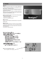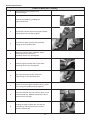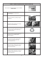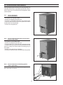
1
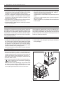
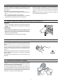
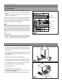
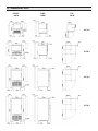
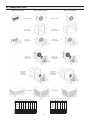
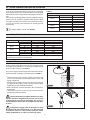
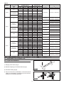
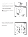
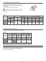
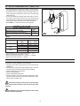
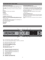
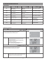
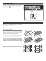
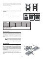
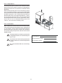
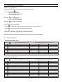
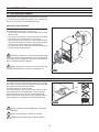
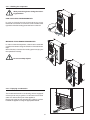
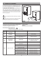
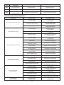
USE AND MAINTENANCE
INSTRUCTIONS
MULTI FRESH "EF"
N° REV
REVISION DESCRIPTION
DATE REV.
REVISER
Dear Customer,
While thanking you for the confidence you have shown us by choosing an IRINOX blast chiller, we invite you to read
this manual carefully. It contains all the information you need to start optimal preservation of your products right away.
We advise you to study the present manual in order to benefit from all the potentialities and advantages that your
IRINOX blast chiller can give you.
Correct operation of the machine also depends on its proper use.
Keep this manual near the blast chiller so that you and your workers can consult it quickly.
Work Well with IRINOX!
Subscribe online to Club Irinox : www.irinox.com
The graphical representation of the controls in this manual is aimed at making it easier to understand the operations
which must be carried out so that you can use your IRINOX blast chiller right away with satisfaction.
Symbol key
Suggestions and details for correct use of the blast chiller
Standards for your safety
Added information in the manual
Information on the warranty and assistance
Warranty validity: for 12 months from the billing date for the individual parts, as carried on the actual price list.
Contacts:
Customer service:
Assistance for use
Technical assistance – spare parts
Fax
E-mail
Web site
+39.0438.5844
+39.0438.5844
+39.0438.2020
+39.0438.2023
[email protected]
www.irinox.com
For any request regarding your blast chiller, always specify:
• The model
• The series number
carried on the machine label.
INDEX
1. GENERAL DOCUMENTATION
4
1.1 GENERAL WARNINGS
4
1.2 PREAMBLE
4
1.3 TRANSPORT AND HANDLING
4
1.4 UNPACKING
4
1.5 ELEMENTARY SAFETY STANDARDS
5
1.6 PRECAUTIONS FOR LOADING AND UNLOADING THE PRODUCTS
5
1.7 DANGEROUS USE OF THE POINTED PROBE
5
1.8 PERIODICAL PERSONNEL TRAINING
5
2. INSTALLATION
6
2.1 PLATE DATA
6
2.2 POSITIONING
6
2.3 DIMENSIONAL DATA
7
2.4 ROOM TEMPERATURE AND AIR EXCHANGE
9
2.5 REFRIGERATION POWER
9
2.6 ELECTRICAL CONNECTION
9
2.7 REFRIGERATOR CONNECTION
10
2.8 CONDENSATION DRAIN
12
2.9 WATER CONDENSING UNIT CONNECTION
13
2.10 INFORMATION FOR THE INSTALLER
13
2.11 SAFETY AND CONTROL SYSTEMS
14
2.12 R404a GAS SAFETY BOARD
14
2.13 DISPOSAL OF THE MACHINE
15
3. OPERATION
15
3.1 USE
15
3.2 DESCRIPTION OF THE CYCLES
16
3.3 CONTROL PANEL
16
3.4 DESCRIPTION AND OPERATION
17
3.5 STOPPING MODES
22
3.6 ADVICE FOR USE
22
3.7 PARAMETER PROGRAMMING
25
3.8 SANIGEN
27
4. MAINTENANCE / ASSISTANCE
30
4.1 ROUTINE MAINTENANCE
30
4.2 CLEANING THE CELL
30
4.3 CLEANING THE CONDENSER
32
4.4 TROUBLESHOOTING
32
4.5 EXTRAORDINARY MAINTENANCE
34
3
1. GENERAL DOCUMENTATION
1.1. GENERAL WARNINGS
• The present manual is an integral part of the product.
It supplies all of the necessary conditions for correct
installation, use and maintenance of the machine.
• The user is obliged to read this manual carefully and
to refer to it always. It must be kept in a known place,
accessible to all authorised operators (installer, user,
maintenance technician).
• The blast chiller is intended for professional use.
Therefore only qualified personnel can use it.
• The blast chiller is destined to be used only for that for
which it was designed.
• The manufacturer declines all liability for damage
caused by improper and unreasonable use, such as:
- improper use by untrained personnel.
- modifications or interventions not specifically for the
model.
- use of non-original spare parts or parts not specifically for the model.
- lack of compliance, even partial, with the instructions
in this manual.
1.2. PREAMBLE
Installation must be carried out by authorised and
specialised personnel, complying with the instructions in
this manual. The manufacturer declares and associates
a declaration of conformity to machinery Directive 98/37,
to Directive 2006/95 and to Directive 2004/108/CE for
each individual machine.
If the machine is supplied with a remote condensing unit,
the installer will take care to check all of the connections
and to leave a declaration that execution was carried out
professionally and in compliance with the provisions of
the above-mentioned Directive.
1.3. TRANSPORT AND HANDLING
• Loading and unloading the appliance from the transportation vehicle can be performed with a forklift truck or pallet
mover. The forks must be longer than half the length of
the appliance. The lifting device must be chosen suitably,
based on the dimensions and mass of the packaged
machine, indicated on the packaging labels.
All due precautions must be taken to handle the appli-
• ance in order not to damage it, respecting the indications
on the packaging.
1.4. UNPACKING
• Remove the cardboard, wooden or crate packaging upon
which the blast chiller is placed. Lift the blast chiller with a
suitable means (lift truck), remove the wooden base and
position the machine in the intended area (see par. 2.2).
• After having removed the packaging, make sure that
the blast chiller is intact.
• Remove the protective PVC film from all sides (Fig.1).
Use protective gloves to handle the packaging
and wooden base.
N.B.: all of the various packaging components must
be disposed of according to the Standards in force in
the Country where the appliance is used. In no case
must anything be dispersed into the environment.
Fig. 1
4
1.5. ELEMENTARY SAFETY STANDARDS
• before carrying out cleaning or routine maintenance,
disconnect the machine from the power supply
network, turning off the master switch and pulling the
plug
• do not pull the power cord to disconnect the machine
from the power supply network.
The user is liable for negligence of operations on the
machine which do not comply with the instructions in
this manual.
Hereafter are the general safety Standards:
• do not touch the machine with wet or humid hands or
feet
• do not operate the machine in bare feet
• do not insert screwdrivers, kitchen utensils or anything
else between the guards and the moving parts
1.6. PRECAUTIONS FOR LOADING AND UNLOADING THE PRODUCTS
LOADING
• When loading the machine, use kitchen gloves in
order to avoid burns due to contact with hot trays and
trolleys.
UNLOADING
• When the blast chilling and/or shock freezing cycles
have ended, open the door slowly until the fans stop.
• Extract the core probe/s from the product and position
it/them on the probe-holder.
• Use suitable gloves for cold trays and trolleys.
1.7. DANGEROUS USE OF THE SHARP PROBE
Use of the probe is allowed only for personnel who are
authorised and trained to use the temperature blast
chiller.
The core probe must be used only for the purpose for
which it was designed: to detect the temperatures at
the centre of the food products to be blasted and/or
frozen.
Handle the probe with care. Its ends are pointed in
order to facilitate its insertion in products to be blasted
and/or frozen.
The ergonomic handle allows correct extraction and
insertion.
1.8. PERIODICAL PERSONNEL TRAINING
All personnel who are authorised to operate the machine
(installer, user, maintenance technician) should be
trained periodically on safety Standards.
In order to avoid accidents or damage to the equipment,
it is also advisable to instruct personnel as to the use
and maintenance of the temperature blast chiller,
referring to this manual which must be kept near the
machine, in a known and accessible spot.
IRIN
Blas OX
Chill t
er
5
2. INSTALLATION
2.1. PLATE DATA
• Make sure that the plate data and electrical line
features correspond (V, kW, Hz, phase and available
power).
• The plate carrying the features of the appliance is
applied on the side (fig.2).
31020
CORBANESE (TV)
ITALY
Model
Series n.
mm/yy/progres.
Mod.
s/n
Preparation of machine rooms to dislocate the condensing
units must comply with the fire-prevention Standards in
force in the Country where the machine is installed (contact
the nearest fire station for due indications).
V
Ph
Hz
A
Compressor
Refrigerant
Remember also that the potential intervention of
safety valves or fuse caps in the refrigeration circuit
entails the immediate discharge of all the refrigerant
used in the ambient. Therefore make sure to realise
opportune means of waste disposal and first aide, as
indicated on the safety cards of the refrigerant ( see
par. 2.12).
Kw
Frequency
HERMETIC
R404
Charge
Power
Desing pressure (Low)
KPa
Desing pressure (High)
KPa
Class
Volume
Phase
Voltage
Rated Load
IP
PED Code
Fig. 2
Climatic class:
• 4 (30°C room temperature with 55% non-condensing
relative humidity) according to Standards CEI EN
60335-1, CEI EN 60335-2-89, ISO 23953-2:2005(E)
2.2. POSITIONING
• The blast chiller must be installed and inspected in
complete compliance with accident-prevention Law
Standards, with traditional rules and with Standards
now in force.
• The installer must check potential fire-prevention
prescriptions (contact the nearest fire station for the
due indications).
• Place the blast chiller in the intended spot.
• Level the appliance by means of the adjustment feet.
Use appropriate lifts to level heavier machinery (Fig.3).
Fig. 3
• If the appliances are not levelled, their operation and
condensation outflow can be jeopardised.
To be avoided (Fig.4):
• Places exposed to direct sunlight
• Closed places with high temperatures and scarce air
exchange (see Table 2).
• Do not install the machine near to any heat sources.
Fig. 4
6
Absorption
2.3. DIMENSIONAL DATA
FRONT
VIEW
SIDE
VIEW
TOP
VIEW
EF10.1
EF20.1
EF30.1
EF45.1
7
2.3. DIMENSIONAL DATA
EF20.1 condensing unit
EF30.1 condensing unit
EF45.1 condensing unit
P1
L1
P1
L1
P1
L1
H1
H1
H1
Remote condenser
Remote condenser
P1
P1
H1
H1
Super-silent
remote condenser
Super-silent
remote condenser
L1
L1
Remote aircondensing unit
Remote aircondensing unit
H
H
P
P
L
L
L1
L1
H1
Remote air
condenser and
remote unit
H1
H
P1
Remote air
condenser and
remote unit
P1
H
P
P
L
L
L1
L1
Super-silent
remote air
condenser and
remote unit
H1
Super-silent
remote air
condenser and
remote unit
P1
H1
H
P1
H
P
P
L
H
L
Housed option
Housed option
H
P
H
L
P
P
L
Remote condensing unit dimensions.
8
STD. AIR
SUPER SIL AIR.
79 80
84 85
56 67
64 103.5
EF45.1
SUPER SIL AIR.
DIM.
(cm)
L1
P1
H1
Kg
EF20.1 EF30.1
STD. AIR
MOD.
HOUSED
REMOTE COND.
AIR
REMOTE COND.
79 80 79
84 85 84
56 67 64
64 99.5 85
HOUSED
AIR
79
84
64
81
AIR
MOD.
EF45.1
78 78
62 63
37 41
40.5 51
MOD.
DIM.
(cm)
L
P
H
Kg
EF30.1
HOUSED
EF20.1
STD. AIR
Remote condensing unit dimensions.
MOD.
L
59
27
29
5.6
58
31
51
13
56
60
75
18
59
33
51
21
89
50
60
23
2.4. ROOM TEMPERATURE AND AIR EXCHANGE
For the air condensed refrigeration units, operating
room temperature must not exceed 32 °C. The declared
performances are not guaranteed beyond this temperature.
The remote condensing units must be installed in appropriate rooms or outside, in a place sheltered from direct
sunlight. If needed, the installer must evaluate using a
cover or roof (in any case sufficient air exchange must
be assured).
Table 2
MINIMUM AIR EXCHANGE
MODEL
Power supply frequency (Hz)
AIR (m3/h)
50
60
50
60
50
60
50
60
1100
1210
3000
3300
3000
3300
EF10.1
EF20.1
EF30.1
EF45.1
For further details, see vedi Table 2.
2.5. REFRIGERATION POWER
Table 3
MODEL
EF10.1
EF20.1
EF30.1
EF45.1
Power supply frequency (Hz) Refrigeration output (W)
50
60
50
60
50
60
50
60
Condensation power (W)
1727
1623
4105
4746
6013
7216
2683
2549
6375
7717
9075
11038
Declared values at evap. T.=-10°C, cond. T.=+40°C and power supply f.=50Hz.
Overheating in compliance with EN12900
2.6. ELECTRICAL CONNECTION
Install a differential automatic circuit-breaker switch
upstream every appliance, according to the Standards
in force in the Country of installation.
The power supply must be brought to the blast chiller electrical control board, according to the data carried on Table 4.
• The electrical power supply cables must have the
correct size and be chosen depending on the real
laying conditions;
• The electrical cables must enter and be blocked in
the appropriate cable sleeve and laid adequately
depending on the installation ambient;
• Each conductor must be inserted in the corresponding terminal;
• The earth conductor must be connected directly to
an effective earthing system.
Fig. 5
The manufacturing company declines all liability and warranty obligations if persons are harmed
or appliances and objects damaged, due to incorrect installation and/or lack of compliance with laws
in force.
Fig. 6
If the power supply cable is damaged, it must
be replaced by the manufacturer or by the technical
assistance service or anyhow by a person with a
similar qualification, in order to avoid every risk!!!
9
Table 4
MODEL
EF10.1
TYPE OF
CONDENSING
UNIT
Voltage (V) Frequency (Hz)
Air
Air
EF20.1
POWER SUPPLY REMOTE CONDENSING
CABLE SECTION UNITS CABLES SECTION
Power (kW) Current (A)
*1
*2
POWER SUPPLY
Remote
air condenser
Water
Air
Remote
air condenser
EF30.1
Remote
super-silent
air condenser
Water
Air
Remote
air condenser
EF45.1
Remote
super-silent
air condenser
Water
ABSORPTION
Poles
230
230
50
50
1P+N+PE
1P+N+PE
230
60
230
230
230
230
400
400
230
230
400
400
230
230
400
400
230
230
400
400
230
230
400
400
230
230
400
400
230
230
400
400
230
230
400
400
230
230
5
6,3
1P+N+PE
1125
1,2
1,3
50
1P+N+PE
1,3
6,7
60
50
60
50
60
50
60
50
60
50
60
50
60
50
60
1P+N+PE
1P+N+PE
1P+N+PE
3P+N+PE
3P+N+PE
3P+PE
3P+PE
3P+N+PE
3P+N+PE
3P+PE
3P+PE
3P+N+PE
3P+N+PE
3P+PE
3P+PE
3P+N+PE
3P+N+PE
3P+PE
3P+PE
3P+N+PE
3P+N+PE
3P+PE
3P+PE
3P+N+PE
3P+N+PE
3P+PE
3P+PE
3P+N+PE
3P+N+PE
3P+PE
3P+PE
3P+N+PE
3P+N+PE
1,4
1,2
1,2
2,9
3,5
3,0
3,7
2,9
3,6
3,0
3,7
2,9
3,5
3,0
6,5
5,9
5,8
5,2
5,2
12,2
12,5
5,4
5,3
12,4
12,7
5,3
5,2
50
60
50
60
50
60
50
60
50
60
50
60
50
60
50
60
50
60
50
60
3P+PE
3P+PE
3,6
2,8
3,4
2,9
3,5
3,7
3,9
3,8
4,7
3,8
3,9
3,9
4,8
3,8
3,9
3,9
4,8
3,6
3,8
3,8
4,6
3G1,5mmq
3x1,5mmq + 3G2,5mmq
3G1,5mmq
3x1,5mmq + 3G2,5mmq
5G1,5mmq
10x1,5mmq + 4G1,5mmq
4G1,5mmq
10x1,5mmq + 4G2,5mmq
10x1,5mmq + 4G4mmq
5G1,5mmq
10x1,5mmq + 4G1,5mmq
4G1,5mmq
10x1,5mmq + 4G2,5mmq
10x1,5mmq + 4G4mmq
5G1,5mmq
10x1,5mmq + 4G1,5mmq
4G1,5mmq
10x1,5mmq + 4G2,5mmq
10x1,5mmq + 4G4mmq
5G1,5mmq
10x1,5mmq + 4G1,5mmq
4G1,5mmq
10x1,5mmq + 4G2,5mmq
10x1,5mmq + 4G4mmq
5G1,5mmq
10x1,5mmq + 4G1,5mmq
4G1,5mmq
10x1,5mmq + 4G4mmq
5G1,5mmq
10x1,5mmq + 4G1,5mmq
4G1,5mmq
10x1,5mmq + 4G4mmq
5G1,5mmq
10x1,5mmq + 4G1,5mmq
4G1,5mmq
10x1,5mmq + 4G4mmq
5G1,5mmq
10x1,5mmq + 4G1,5mmq
4G1,5mmq
10x1,5mmq + 4G4mmq
6,2
12,3
12,5
5,2
5,1
12,2
12,3
5,6
6,0
14,1
14,7
5,7
6,1
14,4
14,9
5,7
6,1
14,4
14,9
5,5
5,9
14,1
14,5
2.7. REFRIGERATION CONNECTION
2.7.1. Equal level installation
General criteria for installation of remote units:
1) Sloping of the ducts (Fig.7).
2%
CO
MP
2) Bracket clamping on insulated tubes (Fig.8).
RE
SS
Fig. 7
3) Hermetic sealing (Fig.9).
4) Vacuum execution (0.03mBar) in connection ducts
(delivery and intake). Condensing unit and Freon
loading, if not indicated differently.
Fig. 8
10
OR
5) Checking vacuum sealing of the ducts.
6) Opening of interception taps on condensing unit.
7) Leakage check.
Fig. 9
8) Checking exact gas loading by means of liquid
passage indicator light placed on condensing unit.
Equal level
installation
9) Checking of condensation water circulation and
pressure (water condensation systems).
The criteria indicated above is sufficient for equal
level installation (Fig.10)
Fig. 10
2.7.2. Different level installation
If the remote unit is installed higher up than the appliance
(fig.12), a siphon must be installed at each start or ascent
(a), every 1.8 metres of difference in level along the return
duct, and at each arrival (b).
Different level
installation
If the remote unit is installed lower than the appliance, no
siphon is needed (fig. 11).
Fig. 11
11
Fig. 12
2.7.3. Refrigerator - remote units connection
The diameters of the supply ducts of the equipment are
dimensioned for installation distances up to 25 metres
(see Table 5).
For greater distances, contact IRINOX SpA.
Insulation of the intake and hot gas line must be
done with a good quality closed-cell insulation, at least
19 mm thick.
19 mm
Table 5
REMOTE UNIT
MODEL
REMOTE
CONDENSER
WATER UNIT
REMOTE CONDENSER AND STANDARD OR
S.SILENT REMOTE CONDENSER
ø IN cond.
ø OUT cond.
ø IN cond.
ø OUT cond.
ø Liquid
ø Intake
mm
mm
mm
mm
mm
mm
mm
8
10
8
8
/
/
/
/
10
16
12
10
12
10
10
16
ø Liquid
ø Liquid
mm
ø IN water
ø OUT water
EF10.1
EF20.1
EF30.1
FE 3/4"
FE 3/4"
EF45.1
2.7.4 R404a pressure switch calibration
For calibration of the R404a pressure switches see Table 6
Table 6
AIR CONDENSATION
WATER CONDENSATION
HIGH P.
FAN
START
SAFETY
VALVE
HIGH P.
SAFETY
VALVE
(Bar)
(Bar)
(Bar)
(Bar)
(Bar)
EF10.1
EF20.1
25
/
17(*1)
/
/
/
EF30.1
27.6
17(*1)
29.5
25
28.5
MODEL
EF45.1
17(*1)
*1: Only when the condensing unit or the condenser is remote.
2.8. CONDENSATION DRAIN
The blast chillers are equipped with a small tray to gather
condensation. The tray can put extracted from the
bottom part of the Blast chiller.
12
2.9. WATER CONDENSING UNIT CONNECTION
• During inspection of the water network, with the machine stopped and the water mains ready, check that the
drain tube of the condenser does not leak water. If it
does, adjust the pressure switch valve until leaking
stops (Fig.13).
• It is recommended to install a water gate and an inspection filter on the water delivery line. The delivery and
drain tube of the condenser are indicated by the appropriate plates. Both connections are 3/4”F threaded.
• See Table 7 for maximum water consumption.
FEATURES OF THE LINE FOR
WATER CONDENSING UNITS
Maximum pressure of inlet water
1600 KPa
Minimum pressure of inlet water
50 KPa
Maximum temperature of inlet water to
guarantee normal operation of the appliance
25°C (well water)
40°C (tower water)
Fig. 13
Table 7
MAXIMUM WATER CONSUMPTION
MODEL
EF20.1
EF30.1
EF45.1
Power supply frequency
(Hz)
50
60
50
60
50
60
WATER
l/h
m3/h
128
103
248
312
345
435
0,13
0,1
0,25
0,31
0,35
0,43
Values referring to an inlet water temperature = 15°C
Maximum inlet water temperature = 22°C
Maximum inlet water pressure to condenser = 1600kPa
Minimum inlet water pressure = 150KPa
2.10. INFORMATION FOR THE INSTALLER
Checking a correct installation and inspection:
• Check for gas leaking from seals or joints made during
installation.
• Check that the connection tubes between the conserver
and the remote condensing unit are well insulated.
• Check the electrical connections.
• Check the absorptions.
• Check the standard pressures.
• Check the water connection with the adjustment of the
pressure switch valve during operation and that condensation water circulates well.
Inform the customer on the exact use of the equipment, with specific reference to the use and needs of the
customer.
Installation and commissioning must be carried
out by authorised personnel.
13
2.11. SAFETY AND CONTROL SYSTEMS
• Door micro switch (A): blocks the fans when the door
is opened.
• Protection fuses (B): protects circuits from short-tcircuits and overloads.
• Fuse holders (C): contain the fuses and allow circuit
opening and disconnection.
• Circuit boards (D): depending on the parameters
acquired, they command and control the various
blast chiller devices connected to them.
• Cell temperature control (E): managed by a circuit
board by means of a PT1000 probe.
• Safety pressure switch (F): intervenes when there is
too much pressure in the refrigerating circuit.
• Safety valve (G): intervenes when there is too much
pressure in the system and when the safety pressure
switch does not intervene. The intervention discharges
excess gas from the ambient.
Fig.A
Fig.B
Fig.C
Fig.D
Fig.E
Fig.F
Fig.G
Fig. 14
2.12. R404A GAS SAFETY BOARD
• Identification of dangers
Elevated inhalation exposure can have anaesthetic
effects. Very high exposure can cause cardiac rhythm
anomalies and cause sudden death. The nebulised or
squirted product can cause frost burns to the eyes or
skin. Dangerous for the ozone layer.
Swallowing
Do not provoke vomiting.
If the injured person is conscious, have the mouth rinsed
with water and have him/her drink 200-300 ml of water.
Seek immediate medical assistance.
Further medical care
Symptom treatment and support therapy when indicated.
Do not administer adrenalin or similar sympathomimetic
drugs after exposure, due to the risk of cardiac arrhythmia
with possible cardiac arrest.
• First aide measures
Inhalation
Move the injured person away from exposure and keep
him/her warm and at rest. Give oxygen if needed. Perform
artificial respiration if breathing has stopped or gives
signs of stopping. In case of cardiac arrest, perform an
external heart massage.
Seek immediate medical assistance.
• Fire-prevention measures
Non flammable.
Thermal decomposition causes the emission of toxic
and corrosive vapours (hydrogen chloride, hydrogen
fluoride). In case of fire, use a self-contained breathing
apparatus and suitable protective clothing.
Skin contact
Have the concerned areas thaw with water.
Remove contaminated clothing.
Attention: clothing can stick to the skin for frost burns.
For skin contact, wash immediately and abundantly
with lukewarm water. If symptoms occur (irritation or
formation of blisters) seek medical assistance.
Fire extinguishers
Use extinguishing agents appropriate for the surrounding fire.
• Toxicological information
Inhalation
More elevated atmospheric concentrations can cause
anaesthetic effects with possible losing of conscience.
Very high exposure can cause cardiac rhythm anomalies
and cause sudden death.
More elevated concentrations can cause asphyxiation
due to the reduced content of oxygen in the air.
Eye contact
Wash immediately with an eye-wash solution or with clean
water, keeping the eyelids aside, for at least 10 minutes.
Seek medical assistance.
14
2.12. R404A GAS SAFETY BOARD
• Measures to be taken in case of accidental leaking
Make sure to have adequate personal protection when
eliminating leakage (using protective devices for the
respiratory tract).
If the conditions are safe enough, insulate the source
of the leakage. If leakage is moderate, let the material
evaporate as long as there is adequate ventilation.
Considerable leakage:
-ventilate the area;
-restrain the poured material with sand, earth or another
suitable absorbing material;
-prevent the liquid from penetrating drains, sewer systems,
basements or work holes, since the vapours can create a
suffocating atmosphere.
Skin contact
Liquid squirts and nebulised liquid can cause frost
burns.
It is improbable that it is dangerous for skin absorption.
Repeated and prolonged contact can cause removal of
skin fat, with consequential drying, chapping and dermatitis.
• Ecological information
It decomposes relatively quickly in the lower atmosphere
(troposphere). The decomposition products are highly
dispersed and therefore have a very low concentration.
It does not affect photochemical smog (this means it is
not included among the volatile organic compounds VOC- according to the UNECE agreement).
The ozone destruction potential (ODP) is 0.055 measured
by a standard ODP equal to 1 for CFC-11 (according the
UNEP definitions).
The substance is regulated by the Protocol of Montreal
(1992 revision).
The discharge of the product released in the atmosphere does not contaminate waters on a long term.
• Handling
Avoid inhaling high concentrations of vapours.
Atmospheric concentrations must be reduced to a
minimum and maintained at the minimum level reasonably possible, below the professional exposure limit.
The vapours are heavier than air. Therefore high concentrations can be formed near the ground where general
ventilation is scarce. In these cases, assure adequate
ventilation or wear suitable protective devices for the
respiratory tract with an air tank. Avoid contact with open
flames and hot surfaces because irritating and toxic
decomposition products can be formed. Avoid contact
between liquid and eyes or skin.
• Considerations regarding disposal
The best solution is to recover the product and have it
recycled.
If this is not possible, destruction must be carried out
in an authorised plant equipped to absorb and neutralise the acid gases and other toxic products.
2.13. DISPOSAL OF THE MACHINE
The demolition and disposal of the machine must be
carried out in compliance with the Standards in force in
the Country of installation, above all concerning refrigerating gas and lubrication oil of the compressor.
The symbol of the barred bin carried on the appliance or on
its packaging indicates that the product must be disposed
of separately from other waste at the end of its life.
Differentiated waste collection of the appliance at the end
of its life is organised and managed by the manufacturer.
The user who wants to free himself of this appliance must
therefore contact the manufacturer and follow the system
that has been adopted to allow separate waste collection
of the equipment at the end of its life.
Adequate differentiated waste collection sending the
appliance on to recycling, treatment or environmentally
compatible waste disposal contributes to avoid negative
effects for the environment and for health and promotes
the reuse and/or recycling of the materials the appliance
is composed of.
Illegal waste disposal of the product by the user entails
the application of administrative sanctions foreseen by
the Standards.
INFORMATION FOR USERS
In compliance with Directives 2002/95/CE,
2002/96/CE and 2003/108/CE, relative to the
reduction of use of dangerous substances in
electrical and electronic appliances, as well
as their waste disposal.
In compliance with Directives 2002/95/CE, 2002/96/CE and
2003/108/CE, relative to the reduction of use of dangerous
substances in electrical and electronic appliances, as well
as their waste disposal.
3. OPERATION
3.1. USE
The temperature blast chillers have been designed to blast the
temperature of just-cooked food, in order to preserve them
longer, maintaining their organoleptic characteristics unchanged.
The Easy Fresh series has been studied to make this operation as easy as possible: few buttons, clear and essential
information for users who approach this new system; the
possibility of customising for more expert users.
The EF series can perform 4 types of blasting:
• DELICATE CHILLING
• STRONG CHILLING
• DELICATE FREEZING
• STRONG FREEZING
15
3.2. DESCRIPTION OF THE CYCLES
DELICATE CHILLING cycle:
With this cycle, food temperature falls rapidly until +3°C
at the core, with an operation temperature between 0°C
and +2°C.
This cycle is particularly indicated for delicate products
like:
Mousse,
Puddings and other spoon desserts,
Creams,
Desserts,
Vegetables,
Less thick foods
DELICATE FREEZING cycle:
This cycle has two shock freezing phases.
In the first phase, the temperature at the core of the product is brought to +6°C, with an operation temperature of
0°C. In the second phase, the core temperature of the
product is brought to -18°C, with an operation temperature that can reach -40°C.
This cycle is particularly indicated for shock freezing:
- baked items
STRONG FREEZING cycle:
With this cycle, the temperature of the product falls
rapidly until -18°C at the core, with an operation temperature that can reach -40°C.
This cycle is particularly indicated for shock freezing of
foods.
STRONG CHILLING cycle:
With this cycle, food temperature falls rapidly until +3°C
at the core, with an operation temperature between
-15°C and +2°C.
This cycle allows reducing work times considerably. It is
particularly indicated for products:
With a high fat content,
Very dense,
Big pieces,
Wrapped
3.3. CONTROL PANEL
DL1
DL3
P3
DL5
P6
DL8
DS1
P1
DL2
DL9
DL4
P4
P2
DS1: Cell temperature display / parameter value
DS2: Core probe temperature display / cycle time / parameter
DL1: DELICATE CHILLING cycle LED
DL2: STRONG CHILLING cycle LED
DL3: DELICATE FREEZING cycle LED
DL4: STRONG FREEZING cycle LED
DL5: Cycle start LED
DL8: Data printing activation LED
DL9: DEFROST cycle LED
P1:
P2:
P3:
P4:
P5:
P6:
P7:
P8:
P9:
P8
DELICATE CHILLING cycle selection key
STRONG CHILLING cycle selection key
DELICATE FREEZING cycle selection key
STRONG FREEZING cycle selection key
Cycle Start/Stop key
Data increase key
Data decrease key
Registered data download key
DEFROST cycle selection key
16
DS2
P5
P7
P9
3.4. DESCRIPTION AND OPERATION
LED description
Off
On
Flashing
DL1
DELICATE CHILLING cycle
not selected
DELICATE CHILLING cycle
selected
Cycle selection standby
DL2
STRONG CHILLING cycle
not selected
STRONG CHILLING cycle
not selected
Cycle selection standby
DL3
DELICATE FREEZING cycle
not selected
DELICATE FREEZING cycle Cycle selection standby
selected
DL4
STRONG FREEZING cycle
not selected
STRONG FREEZING cycle
selected
Cycle selection standby
DL5
No cycle active
Cycle in progress
Cycle start standby /
User parameter
programming
DL8
Data download not in progress
Data download in progress
NOT INCLUDED
DL9
DEFROST cycle
not selected
DEFROST cycle
in progress
NOT INCLUDED
Preliminary Operations
Phase
Front panel screen
Description
FIRST TURN ON
To be carried out after a long period in which
the blast chillier has been without power
1
Power the blast chiller and leave it at “OFF”
for about 60 minutes.
This way the sump resistance will have time
to heat the compressor.
This avoids breakdown at the first turn-on,
due to returning refrigerant liquid.
CHAMBER PRE-COOLING
Before introducing the product in the chamber,
it is recommended to carry out pre-cooling.
1
Start the chosen cycle for at least minutes before
putting the hot food into the blast chiller
17
Blast chiller cycle selection and start-up
Phase
Description
Front panel screen
1
When the blast chiller is powered, on the display
appears:
• Internal chamber temperature
• Blast chiller "OFF" status
2
The DL1, DL2, DL3, DL4 LEDs flash waiting for
selection of the cycle
3
Select the cycle pressing:
• P1
for the DELICATE CHILLING cycle
• P2
for the STRONG CHILLING cycle
• P3
for the DELICATE FREEZING cycle
• P4
for the STRONG FREEZING cycle
The LED of the selected cycle turns on, while the
others turn off.
The DL5 LED
starts to flash
4
If the wrong cycle is selected
press the key of the correct cycle
The cycle LED which was previously selected
will turn off.
The selected cycle LED will turn on
5
Press P5
The DL5 LED
to start the selected cycle.
turns on
The P1
, P2
, P3
keys are disabled.
, P4
, P9
The cycle changes automatically depending on
whether the Core probe is inserted or not.
Core probe inserted:
• the AUTOMATIC mode starts: chill blasting logic
in based on the internal temperature of the product
Core probe NOT inserted:
• the MANUAL mode starts: the chill basting logic
is based on a set time
AUTOMATIC MODE
6A
Insert the Core probe into the product
7A
Close the door of the blast chiller
8A
The cycle starts
On DS1 the cell temperature is displayed
On DS2 the product temperature is displayed
18
Phase
9A
Description
Front panel screen
Pressing P6
and P7
on DS2 the time
gone since the start of the cycle is displayed.
This function can be used at the end of
the cycle to determine the time needed for
blast chilling of a typical product.
That time can be used thereafter to blast chill a
similar product using MANUAL mode.
10A
When the Core probe reaches the temperature
programmed for the chosen cycle (set value),
the cycle ends.
A signal goes off for 5 seconds,
DS1 and DS2 flash.
11A
A product preservation cycle starts.
ATTENTION! Do not use the Blast chiller
as a Conserver.
12A
Press P5
to interrupt preservation.
The Blast chiller goes back to “OFF”.
13A
Open the door of the Blast chiller,
extract the Core probe and place it back into
its housing.
Take the trays out with the blast chilled food and
put them back into a Conserver.
MANUAL MODE
6M
Do NOT insert the Core probe into the product
7M
Close the door of the Blast chiller
8M
The cycle starts.
On DS1 the cell temperature is displayed.
On DS2 the duration of the blast chilling cycle is
displayed in h:mm, where “h” represents the
hours and “mm” the minutes left until the end
of the cycle.
9M
Press P6
or P7
to increase or decrease
the time displayed on DS2.
The time is memorised 3s after the pressing of the
last button.
19
Phase
Description
Front panel screen
10M
When the set time is reached, the cycle ends.
An acoustic signal goes off for 5 seconds.
DS1 and DS2 flash.
11M
A product preservation cycle starts
ATTENTION! Do not use the Blast chiller
as a Conserver.
12M
Press P5
to interrupt preservation.
The Blast chiller goes back to “OFF”.
13M
Open the door of the Blast chiller, take the trays
out with the blast chilled food and put them back
in a Conserver.
Defrost cycle selection and start-up
Phase
Description
Front panel screen
1
The display shows:
• Internal chamber temperature
• Blast chiller "OFF" status
2
The DL1, DL2, DL3, DL4 LEDs flash waiting for
selection of the cycle
3
Press P9
4
The DL5 LED
5
Open the door of the Blast chiller
6
Press P5
to select the DEFROST cycle
flashes
The DL5
and DL9
LEDS turn on
On DS1 the cell temperature is displayed
On DS2 the duration of the defrost cycle is displayed
in h:mm, where “h” represents the hours and “mm”
the minutes left until the end of the cycle.
7
Press P6
or P7
to increase or decrease
the time displayed on DS2.
The time is memorised 3s after the pressing of the
last button.
8
If the door closes during the DEFROST cycle:
• The cycle is suspended
• The remaining time counter blocks
• An acoustic signal goes off
• The “door” symbol flashes
20
Defrost cycle selection and start-up
Phase
Description
Front panel screen
9
When the set time is reached, the cycle ends.
An acoustic signal goes off for 5 seconds.
DS1 and DS2 flash.
10
Press P5
.
The Blast chiller goes back to “OFF”
Data printing selection and start-up
Function
Description
0
Connect the portable printer or the USB Memory
Key to the 9 pole serial socket.
The socket is mounted on the front part of the
electrical control board.
1
The display shows:
• Internal chamber temperature
• Blast chiller "OFF" status
2
The DL1, DL2, DL3, DL4 LEDs flash waiting for
selection of the cycle
3
Press P8
to select printing / download of
registered data
4
The DL8 LED
turns on
On DS1 the cell temperature is displayed
On DS2 “Pri” is displayed
5
When data download is complete, the Blast chiller
goes back to “OFF”
Front panel screen
Registration memory reset
6
with the Blast chiller “OFF” press
P8
and P9
simultaneously;
the DL8 and DL9 LEDs will flash
21
3.5. STOPPING MODES
To turn the machine off in case of an emergency, press
START/STOP P5
board (Fig.15).
and cut power from the main
Fig. 15
3.6. ADVICE FOR USE
Before starting the machine, the inside of the cell must
be cleaned well ( see par. 4.2).
3.6.1. Loading products
Do not cover the trays and containers with lids or plastic
wrap: the greater the food surface exposed to cold air,
the less time will be needed for blast chilling.
It is recommended to use trays and containers as shallow
as possible, and anyhow not more than 6.5 cm deep.
For better results, load the containers with a product weighing 3.5 kg and with a maximum thickness of 8 cm for blast
chilling, or 5 cm for shock freezing. For difficult products
and/or fats, reduce thickness even more.
Make sure to leave enough space between the trays so
that air can circulate adequately.
0,5-2 cm
22
If the machine is not loaded completely, concentrate the
trays in the middle of the blast chiller, placing an empty
tray (A) above the last one.
A
Position the trays in the innermost part of the tray-holder,
making sure that they are as close as possible to the
evaporator.
Do not overload the machine beyond what the manufacturer has established (Tab. “Tray yield and capacity”).
MODELS
Yield
Tray capacity
Blast chilling (Kg) Shock freezing (Kg)
EF5-1
20
15
30
30
EF10-1
45
45
EF15-1
The yield is stated at the following conditions:
- Trays filled with water at 90°C
- Room temperature: 32°C
- No chamber pre-cooling
3.6.2. Pre-cooling
Before a cycle of blast chilling and/or shock freezing, it is
essential to pre-cool the chamber in order to further
reduce work time. Therefore, before inserting the product
to be blast chilled, carry out an empty SOFT or HARD
cycle.
Do not leave the hot product inside of the chamber, in order to avoid damaging the machine.
As soon as the product to be treated is inserted,
start the blast chilling or shock freezing cycle
right away.
3.6.3. Core probe
The core probe must be positioned correctly at the centre
of the largest piece or cut of the product. Make sure that
the point of the probe does not come out of the product
or touch the tray. The probe must be cleaned and sanitised before each work cycle in order to avoid unwanted
contamination.
For better results, load the GN1/1 containers with a
product weighing 3.5 kg and with a maximum thickness
of 8 cm for blast chilling, or 5 cm for shock freezing.
For difficult products and/or fats, reduce thickness even
more.
23
N°
GN
5
10
15
1/1
1/1
1/1
3.6.4. Temperatures
Avoiding having the cooked food to be blast chilled
and/or shock frozen remain for long at room temperature.
The more moisture is lost, the less food softness will be
preserved.
Start the blast chilling and/or shock freezing cycle as
soon as preparation and/or cooking has ended. Make
sure to put the food inside the blast chiller at a temperature that is not below +70°C. Cooked food can enter into
the blast chiller even at very high temperatures (>100°C),
as long as the chamber is pre-cooled. Remember
however that reference times for the cycles start at +90°C
(from +90°C to +3°C or the blast chilling cycle; from
+90°C to -18°C for the shock freezing cycle).
60
50
40
OK!!
30
20
10
NO!!
3.6.5. Preservation
Blast chilled and/or shock frozen food must be properly
covered and protected (with plastic wrap, a hermetic lid
or, even better, vacuum-packed) and marked with an
adhesive label upon which the content, day of preparation and the assigned expiration date are carried, with
indelible writing.
The blast chilled food must be preserved in
a refrigerated cabinet at a constant temperature of +2°C.
CONTENT
Preparation data
The shock frozen food must be preserved in
a freezer cabinet at a constant temperature
of -20°C.
Expiration date
Do not use the blast chiller as a normal refrigerator!
24
3.7. PARAMETER PROGRAMMING
Parameter programming
Parameter programming is accessed with the blast chiller “OFF”.
Press the P5 button
for 5s.
• The DL5 LED will flash
• The DS1 display shows “PrC”
• The DS2 display shows “----”
Press P6
or P7
to select:
1. “PrC”: Cycle parameters
2. “PrC”: Operator parameters
Press P5
to confirm the selection.
Key use for parameter navigation:
- P5 key
: confirms the value selected and passage to the successive value
- P6 key
: increases the value of the selected parameter
- P7 key
: decreases the value of the selected parameter
After the final parameter, programming is exited automatically
60s after the last key was pressed, the programming phase is exited automatically
PrC - CYCLE parameters:
DELICATE CHILLING cycle
Press P1
The DS1 displays shows the set N.
The DS2 display shows the parameter value
set n.
Description
Range
Resolution
1-A
Blast chilling air temp. - S1
-50 ÷ +40°C
1°C
-1°C
2-A
Preservation air temp. - S1
-50 ÷ +40°C
1°C
+2°C
3-A
Cycle end core temp. - S2
-50 ÷ +40°C
1°C
+3°C
1-M
Blast chilling air temp. - S1
-50 ÷ +40°C
1°C
-1°C
2-M
Blast chilling air temp. - S1
-50 ÷ +40°C
1°C
+2°C
3-M
Blast chilling phase duration
1min ÷ 3h
1min / 1h
1:30 min
A = AUTOMATIC mode
Default values
M= MANUAL mode
STRONG CHILLING cycle
Press P1
The DS1 displays shows the set N.
The DS2 display shows the parameter value
set n.
Description
Range
Resolution
Default values
1-A
Blast chilling air temp. PHASE 1 - S1
-50 ÷ +40°C
1°C
-20°C
2-A
Blast chilling air temp. PHASE 2 - S1
-50 ÷ +40°C
1°C
-1°C
3-A
Cycle end core temp.- S2
-50 ÷ +40°C
1°C
+20°C
4-A
Cycle end core temp.- S2
-50 ÷ +40°C
1°C
+3°C
5-A
Preservation air temp. - S1
-50 ÷ +40°C
1°C
-+2°C
1-M
Blast chilling air temp. PHASE 1 - S1
-50 ÷ +40°C
1°C
-20°C
2-M
Blast chilling air temp. PHASE 2 - S1
-50 ÷ +40°C
1°C
-1°C
3-M
Preservation air temp. - S1
-50 ÷ +40°C
1°C
+2°C
4-M
Blast chilling duration PHASE 1
1min ÷ 3h
1min / 1h
30 min
5-M
Blast chilling duration PHASE 2
1min ÷ 3h
1min / 1h
60 min
A = AUTOMATIC mode
M= MANUAL mode
25
DELICATE FREEZING cycle
Press P3
The DS1 displays shows the set N.
The DS2 display shows the parameter value
set n.
Description
Range
Resolution
Default values
1-A
Shock freezing air temp. PHASE 1 - S1
-50 ÷ +40°C
1°C
0°C
2-A
Shock freezing air temp. PHASE 2 - S1
-50 ÷ +40°C
1°C
-40°C
3-A
Preservation air temp. - S1
-50 ÷ +40°C
1°C
-19°C
4-A
Shock freezing cycle core temp. PHASE 1 - S2
-50 ÷ +40°C
1°C
+6°C
5-A
Cycle end core temp.- S2
-50 ÷ +40°C
1°C
-18°C
1-M
Shock freezing air temp. PHASE 1 - S1
-50 ÷ +40°C
1°C
0°C
2-M
Shock freezing air temp. PHASE 2 - S1
-50 ÷ +40°C
1°C
-40°C
3-M
Preservation air temp. - S1
-50 ÷ +40°C
1°C
-19°C
4-M
Blast chilling duration PHASE 2
1min ÷ 8h
1min / 1h
1h
5-M
Blast chilling duration PHASE 1
1min ÷ 8h
1min / 1h
3h
A = AUTOMATIC mode
M = MANUAL mode
STRONG FREEZING cycle
Press P4
The DS1 displays shows the set N.
The DS2 display shows the parameter value
set n.
Description
Range
Resolution
Default values
1-A
Shock freezing air temp. - S1
-50 ÷ +40°C
1°C
-40°C
2-A
Preservation air temp. - S1
-50 ÷ +40°C
1°C
-19°C
3-A
Cycle end core temp.- S2
-50 ÷ +40°C
1°C
-18°C
1-M
Shock freezing air temp. - S1
-50 ÷ +40°C
1°C
-40°C
2-M
Preservation air temp. - S1
-50 ÷ +40°C
1°C
-19°C
3-M
Shock freezing phase duration
1min ÷ 8h
1min / 1h
4h
A = AUTOMATIC mode
M = MANUAL mode
DEFROST cycle
Press P7
The DS1 displays shows the set N.
The DS2 display shows the parameter value
set n.
Description
Range
Resolution
Default values
1
Shock defrosting phase duration
1min ÷ 2h
1min / 1h
30 min
OPERATOR pro - parameters:
The DS1 displays shows the set N.
set n.
The DS2 display shows the parameter value
Range
Default values
Description
1-o
1÷7
1
Day of the week setting
2-o
1 ÷ 12
1
Month setting
08
Year setting
4-o
1 ÷ 23
0
Hour setting
5-o
1 ÷ 59
0
Minute setting
6-o
0÷1
0
Daylight-saving time setting
7-o
0÷1
0
Temperature unit setting
8-o
1 ÷ 15 min
15
3-o
0 = YES
1 = NO
0 = °C
1 = °F
Registration frequency setting
0 = only blast
9-o
0÷1
0
Data registration mode selection
chilling
1 = blast chilling
+ preservation
10-o
1 ÷ 34
Blast chiller number setting
1
1 = Italian
2 = English
11-o
0÷5
1
Language selection for printing
3 = French
4 = German
5 = Spanish
Software release display
12-o
26
3.7. SANIGEN
What is it:
Sanigen is a sanitising system which releases active ions
in order to destroy the microbes in the treated air and on
the surfaces in contact with them.
Since air is the vehicle for the sanitising process, there are
no areas which are inaccessible. A complete sanitation is
guaranteed everywhere.
Sanitising occurs on the surface of the food products and,
most of all, in the atmosphere, which is the vehicle of 97%
of bacterial contaminations for food.
Absence of bacteria allows to obtain the following advantages inside the chamber:
- continuous sanitising of the inside of the cell,
- all surfaces are treated
- there are no unpleasant odours.
Sanigen®
When to use it:
Sanigen must be used when the Blast chiller is not performing any cycle.
How to use it:
Sanigen is installed directly in the factory, when requested.
The operation parameters are set in the Manufacturer
Parameters and are the result of experience and tests in
Irinox laboratories.
Its operation is totally automatic.
How to see if sanitising is active:
The icon appears on the display
27
Routine maintenance:
EVERY 6 MONTHS: Cleaning
0
Cut power from the conserver and
access Sanigen
1
Unhook the outside lug, holding the
glass cylinder still
2
Pull off the external cap from the glass cylinder,
being careful not to break the glass
3
Unscrew the glass cylinder anti-clockwise,
acting on the red plastic base
4
Wash the external cap in lukewarm water,
being careful not to deform it.
Carefully remove any dust deposit
5
Clean the glass cylinder with a moist cloth.
Carefully remove any dust deposit
6
Re-screw the glass cylinder clockwise,
again acting on the red plastic base
7
Check to see if the glass cylinder has any cracks.
If so, the glass cylinder must be replaced
8
Insert the external cap, being sure to place it over
of the internal cap. Maintain a distance of about
5mm from the red base
9
Holding the glass cylinder still, re-insert the
external lug, making sure that it is contact
with the external cap
28
YEARLY: replace the glass cylinder and the external cap
Order the glass cylinder and external cap from IRINOX
CODE 3880410
0
Cut power from the conserver and
access Sanigen.
1
Unhook the outside lug, holding the glass
cylinder still.
2
Unscrew the glass cylinder anti-clockwise,
acting on the red plastic base.
3
Dispose of the glass cylinder with the external
cap as dry waste, since it is made up of
recyclable materials.
4
Check to see if the new glass cylinder has
any cracks. If so, the glass cylinder
must be replaced.
5
Re-screw the new glass cylinder with the
external cap clockwise, again acting
on the red plastic base.
6
Make sure that the external cap covers the
internal cap. Maintain a distance of about
5mm from the red base
9
Holding the glass cylinder still, re-insert the
external lug, making sure that it is contact
with the external cap.
29
4. MAINTENANCE
4.1. ROUTINE MAINTENANCE
The information and instructions in this chapter are intended
for all those who work with the machine: user, maintenance
technician, as well as non-specialised personnel.
Elementary safety Standards
To carry out cleaning and maintenance safely, we recall
the safety Standards in par. 1.5 (Fig.16):
• do not touch or operate the machine with wet or humid
hands or feet,
• do not insert screwdrivers, kitchen utensils or anything
else between the guards and the moving parts
• before carrying out cleaning or routine maintenance,
disconnect the machine from the power supply network,
turning off the master switch and pulling the plug.
• do not pull the power cord to disconnect the machine
from the power supply network.
OFF!!
It is strictly prohibited to remove the guards and safety
devices to carry out routine maintenance. The manufacturing
company declines all liability for accidents caused due to
lack of compliance with this obligation.
Before starting the machine, the inside of the cell
must be cleaned well, as indicated in paragraph 4.2.
Fig. 16
4.2. CLEANING THE CELL
The inside of the cell must be cleaned at the end of every
work day, in order to guarantee hygiene and to safeguard
the quality of the food products treated.
A weekly cleaning is recommended.
The conformation of the cell and of the internal components allow them to be cleaned with a cloth or sponge.
Clean with water and non-abrasive neutral detergents.
Rinsing can be done with a cloth or sponge soaked in water, or
with a light water jet (not greater than the network pressure).
Fig. 17
Do not scrape the surfaces with sharp or abrasive
elements.
Do not use abrasives, solvents or thinners.
Always wear protective gloves while cleaning.
30
4.2.1. Washing the evaporator
Wear protective gloves during the following operations.
HOW TO ACCESS THE EVAPORATOR:
In order to clean the inside of the evaporator, use a
flat-blade screwdriver to loosen the screw located at the
right side of the fan-holding panel and turn it to the left.
METHODS FOR CLEANING EVAPORATOR
In order to clean the evaporator, a brush can be used with
a vertical movement along the direction of the aluminium
flaps.
When finished, close the fan-holding panel carrying out
the operations inversely.
Do not use sharp objects.
4.2.2. Emptying condensation
The models with a built-in condensing unit are equipped
with a special tray to gather condensation and wash
water. It is at the bottom part of the appliance.
Empty and clean the tray periodically, pulling it out from
beneath the appliance using the appropriate handle.
31
4.3. CLEANING THE CONDENSER
For Blast chillers with built-in condensing units, access
the condenser pulling the front flapped grid with force.
For remote condensing units, the air condenser must
be kept clean to allow free air flow.
This operation, which must be carried out at least every 30
days, can be done with non-metallic brushes in order to
remove all dust and down from the condenser flaps. It is
recommended to use a vacuum cleaner to avoid dispersing the dust in the area. Use a brush soaked in alcohol if
there are oily deposits.
Do not scrape the surfaces with sharp or abrasive
elements.
Always wear protective gloves, goggles and masks
protecting the respiratory tract for these operations.
Fig. 18
4.4. TROUBLESHOOTING
The electronic control of the machinery is equipped with a
visual system which signals the presence of alarms.
The alarms are registered on an alarm list.
In case of alarms:
Press P1
Eliminate the cause of the alarm
Electronically-managed diagnostics:
• This symbol turns on
• The alarm Code appears on the DS1 display
Code
Description
AL0
Downloading
default data
AL1
Serial line error
for printing
AL2
Depleted clock module
or battery:
registration block
AL3
Cell temperature
at 40°C during
defrost cycle
Possible cause
Possible solution
Incorrect cable connection
Connect the serial cable of the
printer correctly
Faulty electronics
Replace the circuit board
Depleted clock module or battery:
registration block
Replace circuit board
Cell door micro
switch faulty
Check that the "open door" indicator
signals opening and closing correctly.
If not: intervention of a technician
to replace micro switch.
High work room temperature
Air condition the work room
High room temperature
(above 32°C)
ALP
High pressure alarm
Dirty condenser filter
Clean the condenser
Condenser fan faulty
Intervention of a technician
The starting condenser of the
condenser fan is faulty
Condensation control pressure
switch faulty (only for versions with
remote unit or remote condenser)
Intervention of a technician
High pressure pressure switch faulty
Intervention of a technician
Excessive gas load in system
Intervention of a technician
Compressor discharge tap closed
Open compressor discharge tap
32
Intervention of a technician
Code
Description
Possible cause
Possible solution
AS1
S1 cell probe faulty
S1 probe broken
Replace S1 probe
AS2
S2 cell probe faulty
S2 probe broken
Replace S2 probe
AS3
Total block with probes
S1 and S2 faulty
Probes S1 and S2 are broken
Probes S1 and S2 are broken
NON electronically-managed diagnostics:
Malfunction
The front board does not turn on
The cell fans do not turn
The compressor does not work
The compressor works
but it does not cool the cell
The condensing fan
does not work
The evaporator
does not defrost
Possible cause
Possible solution
No power supply
Check connection
of electrical line
Bus connector between
two boards disconnected
Insert Bus cable in dedicated connector
both in the Front board
and in the Relay board
Protection fuses blown
Replacement of fuses by
authorised technician
No power supply
Check connection
of electrical line
Fan broken
Intervention of a technician
to replace fan
Relay board broken
Intervention of a technician
to replace board
No power supply
Check connection
of electrical line
Auxiliary circuit protection
fuses blown
Replacement of fuses
by authorised technician
Intervention of internal
Klixson for overload
Intervention of a technician
Circuit breaker
switch tripped
Intervention of a technician to rearm
switch and check calibration
Pressure switch intervention
for high pressure
Electronic diagnostic control (ALP alarm).
Intervention of a technician
Relay board
consent missing
Intervention of a technician
to replace circuit board
Remote switch broken
Intervention of a technician
to replace remote switch
No refrigerant gas
Intervention of a technician
Electrovalve broken
Intervention of a technician
Condenser dirty
Pulire batteria condensante
Liquid line electrovalve broken
Intervention of a technician
to replace electrovalve or coil
No power supply
Check connection
of electrical line
Pressure switch broken
Intervention of a technician
to replace device
Fan broken
Intervention of a technician
to replace fan
Start condenser broken
Intervention of a technician
to replace start condenser
Compressor remote switch
consent missing
Intervention of a technician
to replace compressor remote switch
Wrong defrost cycle
programming
Control defrost cycle
programming
33
4.5. EXTRAORDINARY MAINTENANCE
The information and instructions in this paragraph are
intended exclusively for specialised personnel, authorised to intervene on the electrical and refrigeration parts
of the machine.
4.5.1.
How to access the
front circuit board.
• Cut power from the Blast chiller
• Pull the front flapped grid with force
• Access the compartment below the door with the hand
• Unscrew the 2 bushes which fix a plastic box which
contains the front circuit board
• The box can be pulled out
4.5.2.
How to access the electrical control board
and the relay board:
• Cut power from the Blast chiller
• Pull the front flapped grid with force
• The electrical box is on the left part of the blast chiller
• Loosen the screws which block the electrical box and
extract it, pulling it out. Be careful to hold the group of
rear cables
• Pull the cover with force to release it
• Access the electrical control board and the relay board
4.5.3.
How to access the condensing system
(where applicable):
• Remove the rear protection grid loosening the screws
with a flat-blade screwdriver
34
Via Madonna di Loreto, 6/B
31020 CORBANESE (Treviso) Italy
Tel. +39.0438.5844 r.a. - Fax +39.0438.5843
Internet: www.irinox.com
E-mail: [email protected]
Irinox in the world:
IRINOX AUSTRALIA
T. +61 03 968 72500
F. +61 03 968 72544
[email protected]
IRINOX D/A/CH/Lux
Mobil: +49 (0) 172 759 77 91
T. +39 0438 584 222
F. +39 0438 584 120
[email protected]
IRINOX USA
50 Oliver Street - N. Easton, MA 02356
T. +1 508 230 5819
F. +1 508 230 5818
[email protected]
For more information visit
www.irinox.com
Code 443700 - n° rev. 0 - 05/2008 - Printed in Italy
S.p.A.