1
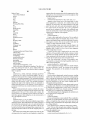
US008239749B2
(12) Ulllted States Patent
(10) Patent N0.:
Williamson et al.
(54)
US 8,239,749 B2
(45) Date of Patent:
PROCEDURALLY EXPRESSING GRAPHIC
OBJECTS FOR WEB PAGES
5,522,022 A
5,537,630 A
5,602,997 A
(75) Inventors: Richard Williamson, San Leandro, CA
i
(Us); David Hyatt, MOunIa1r1V1eW,CA
5,657,049 A
(US); John Louch, San Luis Obispo, CA
5,671,343 A *
(Us)
5,692,205 A *
(73) Assignee: Apple Inc., Cupertino, CA (US)
Aug. 7, 2012
5/1996 Rao etal.
7/1996 Berry et al.
2/1997 Carpenter et al.
gzlrllihefgil'
8/1997 Ludolph etal.
9/1997 Kondo et al. ..
11/1997 Berry et al.
5,708,764 A *
1/1998
5’742’285 A
4/1998 Ueda
..
Borrel et a1. ................ .. 345/419
(Continued)
(*)
Notice:
Subject to any disclaimer, the term of this
patent is extended or adjusted under 35
U.S.C. 154(b) by 633 days.
EP
FOREIGN PATENT DOCUMENTS
548586 A2
6/1993
(Continued)
(21) App1.No.: 11/144,384
_
(22) F1led:
OTHER PUBLICATIONS
Jun. 2, 2005
(65)
Rist et al., Customizing Graphics for Tiny Displays of Mobile
Devices, Google 2002, pp. 260-268.*
Prior Publication Data
US 2006/0005114 A1
Jan. 5, 2006
(Continued)
Related US. Application Data
(60)
Primary Examiner * Cong-Lac Huynh
Provisional application No. 60/583,125, ?led on Jun.
25 2004.
’
(51) IIlt- Cl(52)
(58)
(74) Attorney’ Agent’ or Firm * FenWlCk & West LLP
(57)
ABSTRACT
A graphics object can be expressed using procedural lan
G06F 17/00
(2006.01)
US. Cl. ..................................................... .. 715/211
Field of Classi?cation Search ................ .. 715/200,
guage embedded in a markup language document. In a
embodiment, a drawing space is speci?ed in markup lan
715/211, 205
See application ?1e for comp1ete Search history
object into the drawing space is speci?ed in procedural lan
guage. Interpretation of the markup and procedural language
commands results in the rendering of the arbitrary graphics
56
Rf
e erences C'd
lte
guage- A drawing Command to arbitrarily draW a graphics
' browsercomp"g
o bj ect. I nanot herembd'
o 1ment,t here 1sa
r1s1n
a rendering engine, an interpreter, and parser. The rendering
U.S. PATENT DOCUMENTS
4,752,893 A
6/1988 Guttag etal.
tion that speci?es a drawing space as well as drawing com
5,168,441 A
mands in procedural language for drawing an arbitrary
5,289,574 A
5,297,250 A
5,357,603
5,388,201
5,481,665
5,490,246
A
A
A
A
engine is con?gured to interpret a markup language instruc
12/1992 Onarheimet al.
2/1994 Sawyer
3/1994 Leroy et al.
10/1994
2/1995
1/1996
2/1996
graphic object into the drawing space. The parser can then
parse the drawing commands and convert them into an execu
Parker
HourvitZ et a1.
Okadaet a1.
Brotsky et a1.
tion tree of tree objects.
35 Claims, 6 Drawing Sheets
Browser
m
Rendering Englne
n2
@
E
US 8,239,749 B2
Page 2
US. PATENT DOCUMENTS
5,754,174 A
6,714,201 B1
3/2004 Grinstein et a1.
34588: SE?
5/1998 Carpenter et al.
23192;; 5%
5,761,673 A *
6/1998 Bookman etal. ........... .. 719/311
6’734’864 B2
5764229 A
6/1998
53764238 A
6/1998 Lum etal.
g’zgé’ggg E}
5,781,189 A *
7/1998 Holleran et a1. ............ .. 715/826
6388318 B2
5793376 A
8/1998 Tanaka ‘M1
6,806,892 B1
Bennett
’
5,2004 Ab
’
11
gm
34588: gfhit‘?' '51 """""""" " 345/419
9,2004
ere‘
'
10/2004 Plow et a1
5’796’402 A
8/1998 Ellison'Taylor
6,906,720 B2
6/2005 Emberlin'et a1
5,801,703 A
9/1998 Bowdenet a1.
6’9l0’000 B1
600% Yd-d-
6911584 B2
6,2005 Seb‘n‘ae
5,838,313 A *
11/1998 Hou et a1. ................... .. 715/201
5 838316 A
11/1998
5,877,741 A
’
’
2
Arruza
’
3/1999 Chee et al
341333
’
233%; E;
'
,
gal
'
'
a 6 “ML
,
345882 gaz‘éuez et a1‘
an
0
‘if;
6,978,418 B1
12/2005 Bain et a1. ................... .. 715/205
5,920,659 A
7/1999 Iverson 61211.
$332333 5%
$882 52311212531‘
2,33,33,33 A
5’978’579 A
34333 gkaalital' 1
“H999 Birimiztt‘gl'
7,020,687 B2
7,024,381 B1
3/2006 Mooney et a1. ............. .. 709/206
4/2006 Hastings 6131.
5’999’948 A
0/1999 Nelsonetal'
7,027,055 B2
4/2006 Andersonetal.
6,005,568 A
12/1999 Simonoffet a1.
z’ggg’ggg 5%
‘£882 (sfmtor‘l’ it :11‘
6,006,231 A
12/1999 Popa
7’085’994 B2
8,2006 Girillne e
9/2006 sanoyet al
6,011,562 A
V2000 Gagne “31
7,103,833 B1
6,016,145 A *
1/2000 Horvitz e161. .............. .. 715/788
731273713 B2
28%22; A
$888 iigglygmno
7,174,512 B2
6,076,166 A *
6/2000 Moshfeghi et a1. ............. .. 726/4
zéggggg E;
6,166,748 A
12/2000 Van Hook etal.
6,167,533 A
12/2000 Potterveldet a1.
6182129
Bl*
6’19l’797 B1
6’195’664 Bl
’
1/2001
Roweetal.
7’315’848 B2
7’559’034 B1
................. .. 709/221
2,2001 POMS
2,2001 Tolfa
’
0001
’
‘1
715/206
10,2006 Daviset 3i‘ """"""""" "
2/2007 Martin 6131.
134588;
gt'é'l""""""""" " 715/863
1,2008 Pearseyet a1‘
70009 P
’
tél
apemye
7,667,582 B1
7,975,231 B2
Ohb
'
7157803
'
""""""" "
2/2010 Wa1d_orf ........ ..
340/440
7/2011 Hasl_11ke etal. ............. .. 715/760
2001/0030647 A1
10/2001
2001/0035885 A1
11/2001 Iron 6131.
SOW1Zral et a1.
6,211,890 B1
4
6,246,418 B1
6,266,053 B1
6/2001 Oka
7/2001 French etal'
2002/0008719 A1
2002/0033837 A1
1/2002 Miyawakietal. .......... .. 345/764
3/2002 Munro ........................ ., 345/654
6,266,430 B1
6,272,484 B1
7/2001 RhOaF‘S
8/2001 Ma_rt1netal.
2002/0065949 A1
20020067418 Al
5/2002 Heaton
mom I
2002/0072956 A1
6/2002 Willems et a1. ............... .. 705/10
6,272,558 B1
8/2001
6,278,448 B1
8/2001 Brf’wn etal'
Huletal'
2002/0089526 A1
7/2002 Buxton etal.
2,3831%: 5%
18/388} lililzyporfk etal'
2002/0093516 A1
7/2002 Brunneretal.
6,321,314 B1
“0001 vjn‘jftlfe'
2002/0099678 A1
7/2002 Albright et a1.
2002/0118217 A1
8/2002 Fujiki
’
’
Y
6,369,823 B2
6,369,830 B1
‘V2002 Ohba
‘V2002 BmPner 6‘ a1~
2002/0120673 A1
2002/0129092 A1
6,396,520 B1
5/2002 orqmg
2002/0171682 A1
2,3339} E1
2588; gglgérftal'
2002/0174003 A1 11/2002 Redmann 6131.
6,418,439 B1* 7/2002 Papierniak
etal. ................. .. 1/1
.
gggggiggg; A;
6,421,058 B2
6,424,348 B2
2003/0009267 A1
2003/0020671 A1
7/2002 Pwkh etal'
7/2002 Pwkh
8/2002 Tolson 6131.
9/2002 Tolson 6131.
11/2002 Frank 6131.
34588; Eves‘.
a lZ et a1.
1/2003 Dunsky etal.
1/2003 Santoro 6131.
6,452,600 B1
9/2002 Pwkh etal'
2003/0023770 A1
1/2003 Barmettler et a1. ......... .. 709/327
6,456,290 B2
6,457,034 B1
9/2002 Pankl} etal'
9/2002 M‘ireln
2003/0046316 A1
2003/0080995 A1
3/2003 Gergic etal.
5/2003 Tenenbaum e131.
2,2123%?‘ 5% 18/588; girélt‘ilneétaii
6,483,524 B1
2003/0101046 A1
5/2003 Krasnov
11/2002 Perohenkineet a1.
2003/0123739 A1
700% Graffagmn"
.
2003/0124502 A1
7/2003
2003/0146934 A1
8/2003 Bailey 6131.
g
2003/0158975 A1
8/2003
2,25%‘; 3}
34588; $2323
2003/0164831 A1
9/2003 Walls etal. ................. .. 345/505
6,552,732 131*
4/2003 Davis et a1‘ “““““““““ “ 345/619
2003/0164862 A1
9/2003 CadlZ e? a1~
’
’
2,253,233 5% 13588; i/laFlllkh etall'
6,526,174 B1
’
’
2/2003 Grlaf‘geltliié)
’
’
2003/0154239 A1
.
6,571,328 B2
5/2003 L‘a‘’ “31
2,25%; 3}
24588; 3131.1“ J“ let 31'
6,583,892 B2,,
600% Ti’niliaeta'
22382; 3}
6,614,444 B1
$88; $301.‘ “3151
900% Dullfllliz‘iretet 51
’
’
6,618,048 B1
"""""""""""""""""" "
9000} L th’
'
358/19
'
'
Chou
.......................... .. 434/350
8/2003 Davis etal.
Franketal.
2003/0174136 A1
9/2003
2003/0174154 A1
9/2003 Yukie @131.
Emberllng et al.
2003/0184552 A1
10/2003 Chadha ....................... .. 345/581
2003/0189597 A1
10/2003 Anderson 6131.
2003/0191799 A1
10/2003
2003/0225740 A1
2004/0012626 A1
12/2003 Sexton et a1. ................... .. 707/1
1/2004 Brookins
2004/0032409 A1
Araujo et al.
2/2004 Glrard
6’636’214 B1
10,2003 Lgjthgetal
2004/0036711 A1
2/2004 Anderson
B1
10/2003 Drebin et a1"
2004/0039987 A1
2/2004 Coppin e1
6,664,958 B1
12/2003 Leatheretal.
2004/1003993
2/2004 La9deta1'
6,664,962
6,668,353
6,674,438
6,684,369
6,691,176
12/2003
12/2003
1/2004
1/2004
2/2004
2004/0143823
2004/0179019
2004/0194020
2004/0212640
2004/0215740
B1
Bl*
B1
B1*
Bl*
Komsthoeft et a1‘
Yurkovic .................... .. 715/205
Yamamoto et a1,
Bernardo et a1. ........... .. 715/205
Narin et a1. ................. .. 719/318
A1
A1
A1
A1
A1
7/2004
9/2004
9/2004
10/2004
10/2004
.............. .. 715/502
W61 ............................. .. 717/140
Sabella etal
Beda et a1. .................. .. 715/502
Mann et 81.
Frank et a1.
6,697,074 B2
2/2004 Parikh et a1.
2004/0223003 A1
11/2004 Heirich et a1.
6,707,462 B1
3/2004 Peercy et a1.
2004/0255253 A1
12/2004 Marcjan
US 8,239,749 B2
Page 3
2004/0261012
2004/0261037
2004/0261038
2005/0010634
2005/0021935
2005/0022139
2005/0039144
2005/0057497
2005/0060655
2005/0060661
2005/0088447
2005/0088452
A1
A1
A1
A1
A1
A1
A1
A1
A1
A1
A1
A1
2005/0091571 A1*
2005/0091576 A1*
2005/0108364 A1*
2005/0144563
2005/0168471
2005/0168476
2005/0181349
2005/0193368
2005/0240857
12/2004 Balsiger
Yee, Peephole Displays: Pen Interaction on Spatially Aware
Handheld Computers, ACM 2003, pp. 1-8.*
Duce et al., Web 2D Graphics File Formats, Google 2002, pp. 43 -65 .*
12/2004 Ording et al.
12/2004 Ording et al.
1/2005 Henderson et al.
Lin et al., DENIM: Finding a Tigher Fit between Tools and Practice
for Web Site Desigh, ACM 2000, pp. 510-517.*
Jern, 3D Data Visualization on the Web, IEEE 1998, pp. 90-99.*
Microsoft Corporation, User’s Guide Microsoft® WindowsTM and
MS-Dos® 6, 1993, pp. Cover-Xvi, 112-121.
Microsoft Corporation, Micro soft® WindowsTM User’ s Guide for the
Windows Graphical Environment, Version 3.0 for the MS-DOS® or
1/2005 Schillings et al.
1/2005 Gettman et al.
2/2005 Wada et a1.
3/ 2005 Kawahara
3/ 2005 Gray et al.
3/ 2005 Kawahara et a1.
4/2005 Hanggie et al.
4/2005 Hanggie et al.
4/2005
4/2005
5/2005
A1
6/2005
A1
8/ 200 5
A1
8/ 2005
A1* 8/2005
A1
9/2005
A1
10/2005
Leichtling ................... .. 715/500
Relyea et al. ............... .. 715/502
Callaghan et a1. .......... .. 709/219
Hough et al.
Paquette
PC-DOS Operating System, 1990, Document No. SY06851-0290,
pp. Cover-vii, 15-76, 315-354.
Conner, D., et a1. “Three-Dimensional Widgets,” ACM, 1992, pp.
183-231.
Levene et al.
“Stardock News: DesktopX User Manual On-line,” 1999, 2003,
[online] [Retrieved on May 11, 2007] Retrieved from the Internet
Bardige et al. .............. .. 434/362
<URL:http://www.stardock.com/newsitem.asp?id:538>.
Becker et a1.
Benedict et al.
“Comparison of widget engines” Wikipedia, 2007 [online]
Silverbrook et al. ...... .. 358/1.18
[Retrieved on Sep. 28, 2007] Retrieved from the Internet <URL:
2005/0243373 A1*
11/2005
2005/0256940 A1
11/2005 Henderson et al.
http://en.wikipedia.org/wiki/Comparisoniofiwidgetiengines>.
2005/0268215 A1*
12/2005
“Dashboard Blog,” Dec. 2003 [online] [Retrieved on May 11, 2007]
Retrieved from the Internet <URL:http://www.nat.org/dashboard/
Battagin et al. ............. .. 715/503
2005/0278651 A1
12/2005 Coe et al.
2005/0283734 A1
12/2005 Santoro et al.
2006/0035710 A1* 2/2006 Festejo et al.
2006/0059422 A1*
2006/0059423 A1*
3/2006
3/2006
blog.php3>.
.. 463/36
. 715/513
Wu et al. ...... ..
Lehmann et al. ........... .. 715/530
2006/0075141 A1
4/2006 BoXenhorn
2006/0090137 A1*
4/2006 Cheng et a1. ................ .. 715/758
Stardocl<.com, et al., “DesktopX Whitepaper and Users Guide,”
Stardocl<.com, et al., 1999 [online] [Retrieved on May 14, 2007]
Retrieved from the Internet <URL:http://www.stardock.net/media/
whitepaperidesktopx.html>.
2006/0109275 A1*
5/2006
2006/0123356 A1
6/2006 Sobeski et al.
“Windows Sidebar” Wikipedia, 2007 [online] [Retrieved on May 29,
2007] Retrieved from the Internet <URL: http://en.wikipedia.org/
2006/0136843 A1*
2006/0136868 A1*
6/2006
6/2006
Shafron ...................... .. 715/826
Celi et al. .................... .. 717/106
wiki/Windows-Sidebar>.
Gruber, J ., et al., “Dashboardvs. Konfabulator,” Daring Fireball, Jun.
Chaudhri et a1.
Forstall et al.
Chaudhri et a1.
Forstall et al.
Fellman
Amadio et al.
Slothouber et a1.
2004, [online] [Retrieved on May 11, 2007] Retrieved from the
2006/0206835
2006/0274086
2006/0277469
2006/0277481
2007/0038934
2007/0044039
2007/0061724
2007/0073641
2007/0101146
2007/0101279
2007/0101288
2007/0101291
2007/0101297
2007/0101433
2007/0118813
2007/0130541
2007/0162850
2007/0203984
2007/0209013
2007/0233736
2007/0266093
2008/0072157
2008/0136822
2008/0163076
2008/0209008
2008/0306933
A1
A1
A1
A1
A1
A1
A1
A1*
A1
A1
A1
A1
A1
A1
A1
A1
A1
A2
A1
A1
A1
A1*
A1*
A1*
A1*
A1*
9/ 2006
12/ 2006
12/ 2006
12/ 2006
2/2007
2/2007
3/2007
Cho ............................ .. 345/522
Internet
“Snippets Software Platform,” Snippet Software Inc., Jun. 2001,
[online] [Retrieved on Jun. 11, 2001] Retrieved from the Internet
<URL:http://www.snippets.com/products/>.
3/2007
Perry et al. ...................... .. 707/2
5/2007
5/2007
5/2007
5/2007
5/2007
5/2007
5/2007
6/2007
7/2007
8/2007
Louch et a1.
Chaudhri et a1.
Forstall et al.
Forstall et al.
Forstall et al.
Louch et a1.
Forstall et al.
Louch et a1.
Adler et al.
AlHusseini et al.
OpenGL® Graphics System, CS448 Lecture 15 [online] Fall,
2001Retrieved from the Internet: <URL: http://www.graphics.
stanford.edu/courses/cs448a-01-fall>, pp. 1-20.
CadiZ, JJ et al., “Sideshow: Providing Peripheral Awareness of
Important Information,” Technical Report MSR-TR-2001-83, Sep.
14, 2001, Microsoft Corporation, Redmond, WA, 9 pages.
Elliott, Conal, “Programming Graphics Processors Functionally,” 11
pages.
Nvidia, “CgiTeaching Cg,” Power Point Presentation, Author and
11/2007 Forstall et al.
Pally ........................... .. 715/738
Schorr et al. ................ .. 345/441
date unknown, pp. 1-16.
Segal, Mark et al., “The OpenGL® Graphics System: A Speci?cation
(Version 1.5),” Silicon Graphics, Inc., Oct. 30, 2003, 334 pages.
7/2008 Reponen et al.
. 715/760
8/2008
. 709/219
ShantZis, Michael A., “A Model for Efficient and Flexible Image
707/5
Computing,” Computer Graphics Proceedings, Annual Conference
. 719/328
Series, Jul. 24-29, 1994, pp. 147-154, Orlando, FL.
Van Gelder, Allen et al., “Direct Volume Rendering with Shading Via
Three-Dimensional Textures,” University of California, Santa Cruz,
CA, 9 pages.
Fried, Ina, “Developer Calls Apple’s Tiger a Copycat,” CNET News.
com, Jun. 28, 2004 [online] [Retrieved on Jul. 1, 2004] Retrieved
from the Internet<URL:http://Zdnet.com.com/2102-1104i2
Kim et al.
.... ..
12/2008 Valliani et al.
2009/0007160 A1*
1/2009
2009/0077158 A1*
3/2009 Riley et al. .................. .. 709/202
Wei ........ ..
FOREIGN PATENT DOCUMENTS
EP
EP
EP
W0
W0
W0
Snippet Software Inc. et al., “Product Spotlight Non-browser based
portal solution from Snippets Software, Inc.,” Corporate Portal Let
ter, Oct. 2000, 3 Pages, vol. 1, No. 10.
Akeley, Kurt et al., “Real-Time Graphics Architecture,” The
9/2007 Ramsey et al.
10/2007 Xiong et al.
3/2008
6/2008
<URL:http://daring?reball.net/2004/06/dashboardivsi
konfabulator>.
0694879
1383080
0 972 273
WO 98/45815
WO 02/09039
WO 2004/027707
A2
A1
B1
A2
A2
1/1996
1/2004
3/2004
10/1998
1/2002
4/2004
OTHER PUBLICATIONS
Linton et al., Composing User Interfaces with InterViews, IEEE
1989, pp. 8-22.*
Nigay et al., A Design Space for Multimodal Systems: Concurrent
Processing and Data Fusion, ACM Apr. 1993, pp. 172-178.*
Billinghurst et al., 3D Palette: A Virtual Reality Content Creation
Tool, ACM 1997, pp. 155-156.*
250692.html?tag:printthis>.
Fried, Ina, “For Apple’s Tiger, the Keyword is Search,” CNET News.
com, Jun. 28, 2004 [online] [Retrieved on Jul. 1, 2004] Retrieved
from
the
Internet<URL:http://Zdnet.com.com/2102-1103i2
250346.html?tag:printthis>.
Haeberli, P. et al., “The Accumulation Buffer: Hardware Support for
High-Quality Rendering,” Computer Graphics, Aug. 1990, pp. 309
318, vol. 24, No. 4.
International Search Report, PCT/US2005/008804, Jul. 27, 2005, 3
pages.
US 8,239,749 B2
Page 4
International Search Report, PCT/US2005/008805, Aug. 8, 2005, 3
pages.
Konfabulator, “Cupertino, Start Your Photocopiersl,” [online]
[Retrieved on Jul. 1, 2004] Retrieved from the Intemet<URL: http://
www.konfabulator.com>.
Konfabulator, Konfabulator & Widget Basics, [online] [Retrieved on
Jul. 1, 2004] Retrieved from the Internet<URL: http://www.
konfabulator.com/info/basics.html>.
Konfabulator, “Screenshots,” [online] [Retrieved on Jul. 1, 2004]
Retrieved from the Internet<URL:http://www.konfabulator.com/
info/screenshots.html>.
Konfabulator, “What is Konfabulator?,” [online] [Retrieved on Jul. 1,
2004] Retrieved from the Internet<URL:http://www.konfabulator.
com/info/>.
Noti?cation of Transmittal of the International Search Report and the
Written Opinion of the International Searching Authority, PCT/
US2005/022579, 14 pages.
Puder, A., “Extending Desktop Applications to the Web,” ACM Inter
national Conference Proceedings Series, Proceedings of the 2004
International Symposium on Information and Communication Tech
nologies, 2004, vol. 90, 6 pages.
Rochkind, M. et al., “Common Elements in Today’s Graphical User
Interfaces: The Good, the Bad, and the Ugly,” INTERCHI ’93, ACM,
Apr. 24-29, 1993, pp. 470-473.
ShioZawa, HidekaZu et al., “Perspective Layered Visualization of
Collaborative Workspaces,” Proceedings of the International ACM
SIGGROUP conference on Supporting Group Work Publisher, Nov.
1999.
Staples, Loretta, “Representation in Virtual Space: Visual Conven
tion in the Graphical User Interface,” Proceedings of the SIGCHI
Conference on Human Factors in Computing Systems, Apr. 1993.
Tang, J .C. et al., “ConNexus to Awarenex: Extending Awareness to
Mobile Users,” SIGCHI ’0l, ACM, Mar. 3l-Apr. 4, 2001, 8 pages.
Wardell, Brad, Konfabulator for Windows, Jan. 10, 2004;
[online]Retireved from the Internet Mar. 6, 2006] Retrieved from the
Internet:<URL:
http://www.xpthemes.com/forums.asp?MID:l9
&CMID:l9&AID:4472>.
International Search Report and Written Opinion, PCT/US2005/
022152, Jul. 10,2006, 8 pages.
Archive of “Objects, Images and Applets,” W3C Recommendation,
Feb. 10, 2003, [online] [Archived by http://archiveorg; Retrieved on
Apr. 13, 2006] Retrieved from the Internet<URL:http://web.archive.
org/web/200302l0l540l9/http://www.w3.org/TIUREC-htmll40/
struct/obj ects.html>.
Ullenboom, C., “Java is auch eine Insel,” 2003, [online] [Retrieved on
Apr. 13, 2006] Retrieved from the Internet<URL:http://www.
galileocomputing.de/openbooldjavainsel2//javail40000.
htm#Xxx998l38>.
Altman, R. B., “Visual QuickStart Guide Power Point 2000/98,
Applying Preset Animations,” ProQuest Safari Books, Peachpit
Press, May 7, 1999, 7 pages [online] Retrieved from the Internet:
<URL: http://proquest.safaribooksonline.com/020l3544l l>.
Stardock et al., “DesktopX General Guide,” Aug. 2000, [online]
[Retrieved on Jan. 3 l, 2008] Retrieved from the internet <URL:http://
www.stardock.com/products/desktopx/docs/>.
Stardock et al., “DesktopX WhitePaper,” Aug. 2000, [online]
[Retrieved on Jan. 3 l, 2008] Retrieved from the internet <URL:http://
www.stardock.net/media/whitepaperidesktopx.html>.
Stardock et al., “DesktopX Tutorial,” Aug. 2000, [online] [Retrieved
on Jan. 31, 2008] Retrieved from the internet <URL:http://www.
stardock.com/products/desktopx/tutorial.html>.
Stardock et al., “What Can It Do? Making Objects,” DesktopX Tuto
rial, 2001, [online] [Retrieved on Apr. 11, 2008] Retrieved from the
Internet <URL:http://web.archive.org/web/200l l0l9222825/http://
www.stardock.com/products/desktopx/. . .>.
Snippets Software et al., “Products: Overview,” Feb. 2002, [online]
[Retrieved on Feb. 5, 2008] Retrieved from the Internet URL:http://
web.archive.org/web/2002020606l508/http://www.snippets.com/
products/>.
Unknown, “Convert just about Anything to Anything else,”
OnlineConversion.com, Aug. 2000, [online] [Retrieved on Jun. 22,
200 8] Retrieved from the internet <URL:http://web.archive.org/web/
200008l5055422/http://www.onlineconversion.com/>.
Examiner’s First Report on Australian Patent Application No.
2005267626, Feb. 10, 2010, 3 Pages.
“Writing a Desk Accessory,” Developer Connection, Apple Com
puter, Inc. Jul. 3, 1996, [online] [Retrieved on Jan. 3, 2006] Retrieved
from the Internet<URL:http://developer.apple.com/documentation/
Communication of the European Patent Of?ce dated Oct. l, 2010, for
European Patent Application No. EP05766079.7, 5 pages.
mac/Devices/Devices-l6>.
* cited by examiner
US. Patent
Aug. 7, 2012
Sheet 1 of6
mku
pf
L¢<mquatsdnmbAiAloeGutnp(yO%>l.L{bac
f
-
m
_
w
-
M
m
m
.meVmm
_
Re n
nw
r
e
m
.namrn
a
e
Era
m
dBeAlP
US 8,239,749 B2
g
|d.m0O
em
mm
mm
HvM
w
grS
r.\l).
Wepage
text text text
text text
text text text
text text text
text text text
text
text text text
text text text
text text text
Figure 1
152
US. Patent
Aug. 7, 2012
US 8,239,749 B2
Sheet 2 0f 6
Specify Canvas / Canvas Element
m
Retrieve Canvas Element
Retrieve Drawing Object / Context Object
23g,
Code Drawing Commands to Create AGO
259
Figure 2
US. Patent
Aug. 7, 2012
Sheet 3 of6
Load markup page
US 8,239,749 B2
319
i
Begin event loop
l
l
l
l
l
l
1
:20
Parse page I create tree
data structure
332
Pass scripting commands
to interpreter
35.0.
Parse commands I convert
into execution tree
Create render tree
m
iterate over render tree I
am
instruct each object to draw itself
End event loop
38-0
Composite off-screen bitmap
into onscreen surface
Figure 3
1”
US. Patent
Aug. 7, 2012
Sheet 4 of6
San Francisco
Honk Kong
Figure 4
US 8,239,749 B2
US. Patent
Aug. 7, 2012
Sheet 6 of6
apply transformation matrix to coordinates
610
l
render painting/drawing operations to
create intermediate image
620
i
apply shadow to intermediate image to
create resulting image
630
modify resulting image per GlobalAlpha
640
composite resulting image into page
650
Figure 6
US 8,239,749 B2
US 8,239,749 B2
1
2
PROCEDURALLY EXPRESSING GRAPHIC
OBJECTS FOR WEB PAGES
and rendering capabilities using a procedural interface to
create graphics objects for use in Websites.
SUMMARY OF THE INVENTION
CROSS-REFERENCE TO RELATED
APPLICATIONS
The present invention relates to a novel approach to creat
ing graphics object for Website applications. As used through
This application claims the bene?t of US. Provisional
Patent Application 60/583,125 entitled “Procedurally
Expressing Graphic Objects for Web Pages”, to Williamson,
out this disclosure, the term “arbitrary graphics object” or
AGO refers to any graphical output rendered procedurally,
et. al. ?led Jun. 25, 2004, Which is hereby incorporated by
including, but not limited to, a tWo or three dimensional
image or scene, produced based on the execution of proce
dural commands. The execution of the commands may be
carried out in a graphics context that supports vector graphics,
reference in its entirety; this application is related to US.
patent application Ser. No. 10/877,968 entitled “Uni?ed
Interest Layer For User Interface”, to Chaudhri, et. al. ?led
Jun. 25, 2004, Which is hereby incorporated by reference in its
Scalable Vector Graphics, OpenGL or other types of existing
entirety.
and emerging graphics platforms, or may also utiliZe more
conventional graphics formats such as Postscript, TIFF, PDF,
BACKGROUND
PICT, BMP, WMF, GIF, JPEG, PNG, and EPS.
In an embodiment, a draWing area into Which anything can
1. Field of the Invention
The present disclosure relates in general to computer
20
graphics and in particular to procedurally expressing arbi
trary graphic objects in markup language documents.
2. Background of the Invention
Web pages are created using markup languages such as
HTML (HyperText Markup Language), XHTML (Extensible
HyperText Markup Language), and SGML (Standard Gener
aliZed Markup Language). Designed to be interpreted by
25
ics, to draW into the draWing area. According to one embodi
ment of the invention, a markup language, such as HTML, is
used to specify a graphical element, referred to throughout the
disclosure as a “canvas.”A procedural language such as Java
Script is used to draW into that graphical element. Also cre
different broWsers, markup languages alloW for a diversity of
content to be expressed in a relatively simple and static code
structure. While poWerful, markup languages are often not
be draWn using draWing commands is described in a markup
language. The AGO is then expressed in the form of arbitrary
draWing commands, such as those provided in vector graph
ated is a context object that can render into the canvas using a
paintbrush-like metaphor. Any graphics language can be use
30
to specify the graphical content to be draWn Within the ele
Well-suited for supporting dynamic, scalable, and complex
ment or canvas; such language can include vector graphics
graphics. As a result, most Website images comprise raster
commands such as pathing, stroking, and ?lling. The canvas
itself may also be manipulated in terms of other markup
constructs such as Content Style Sheets (CSS). During an
event loop, the procedural commands are translated into
graphics code, Which is executed to dynamically generate the
iZed graphic objects using such formats as .GIF or .JPEG.
Graphic formats such as vector graphics offer a number of
advantages over rasteriZed graphics. Vector graphic images
35
are generated by interpreting a series of vectors, or path
descriptions, and stroking or ?lling those paths. The resulting
images are fully resolution-independent and scalable and
graphics object. The object is then composited for display.
therefore, unlike rasteriZed images, can be scaled up or
and images on the ?y using graphics concepts such as mask
enlarged While maintaining the same quality. Formats for
three-dimensional graphics like OpenGL and Direct3D as
Well as other formats currently offered and under develop
This series of steps can be used to arbitrarily render scenes
40
ing, pathing, and transparency. The resulting arbitrary graph
ics object may be resolution-independent and fully scalable,
often consumes less space than conventional graphics ele
ment are similarly procedural in nature, and thus are not
ments, and can utiliZe existing and emerging graphics and
naturally described in markup language. In addition to being
scalable, vector graphics and related graphic formats also
alloW for dynamic rendering. This capability alloWs for inter
rendering capabilities.
45
such technologies, the methods and systems of this disclosure
may be advantageously implemented using a variety of exist
activity and also permits equivalent ?les to be more compact
since graphical images and scenes are generated just prior to
their display.
These and other bene?ts make vector graphics, OpenGL,
ing and emerging graphics, broWser, and related technologies
50
and other formats Well-suited for use in Web pages. HoWever,
existing approaches to providing such arbitrary formats on
the Web have signi?cant draWbacks. Flash vector graphic
?les, for instance, are bulky and typically can’t be accessed
unless the user doWnloads a plug-in containing a rendering
Although reference throughout this disclosure is made to
particular operating platforms, graphics, Web broWsers, and
in a variety of different operating environments.
In an embodiment, an arbitrary graphics object is
expressed in computer code. A draWing space is speci?ed in
a markup language, and a draWing command is speci?ed in a
procedural language to draW the arbitrary graphics object into
55
the draWing space. In another embodiment, there is a com
engine equipped With special capabilities. Previous attempts
puter program product comprising instructions for specifying
to create a 3D markup language, notably VRML (Virtual
Reality Modeling Language) have as yet been unsuccessful.
In addition, many graphics concepts such as iteratively draW
ing paths are more naturally described in procedural language
rather than using the markup interface such as that used by
VRML or SVG. Although adding procedural commands,
scripted for instance in JavaScript, to Web pages may enable
the dynamic manipulation of images, it still does not alloW for
the draWing of arbitrary images into a Web page or confer the
a graphics object. The instructions include a command in
markup language for de?ning a draWing space, and a com
mand in scripting language for draWing the arbitrary graphic
60
object. In an embodiment, there is also an instruction for
specifying a command in the procedural language to retrieve
the draWing space.
In another embodiment, a graphics object can be expressed
using an interactive user interface. In response to input from
65
the user, a markup language command that speci?es a height
other advantages associated With arbitrary graphic formats.
dimension and a Width dimension of a draWing space is
Thus, What is needed is a Way to leverage existing graphics
coded. In addition, scripting language commands are coded
US 8,239,749 B2
3
4
for arbitrarily drawing the graphics object in the drawing
although the methods described herein are primarily dis
closed in the context of a browser, in various alternatives they
may be carried out by various computer or other applications
including an application for a desktop, laptop, or handheld
space, responsive to user input representing the object.
BRIEF DESCRIPTION OF THE DRAWINGS
computer or handheld device, a game application, or a graph
ics application. In another embodiment, an application that
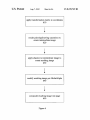
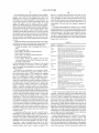
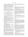
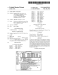
FIG. 1 depicts a high level view of the operating environ
can interpret one or more markup languages such as HTML,
ment in and elements with which a graphics object can be
expressed in accordance with an embodiment of the inven
tion.
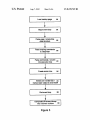
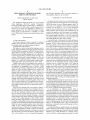
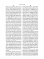
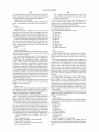
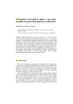
FIG. 2 depicts a ?ow chart of steps to code a sample AGO
into a markup page.
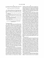
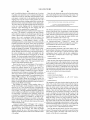
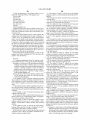
FIG. 3 illustrates the steps performed by a browser to create
anAGO in a website during the process of rendering a markup
XHTML, and XML may be used.
As described above, the browser 110 includes a rendering
engine 112, an interpreter 116, and a parser 118. The render
ing engine 112 is built on conventional or emerging rendering
and layout engine technology such as used by the Gecko
engine of MoZilla, or Webkit of OSX and interprets and
renders the markup page. The rendering engine 112 includes
an interpreter 116 for interpreting the PL and for interpreting
language page.
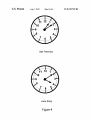
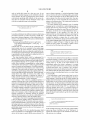
FIG. 4 depicts a sample vector graphics image generated
using the techniques described herein.
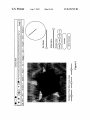
FIG. 5 is a screen shot of a user interface that could be used
to create a graphics object.
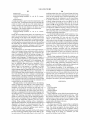
FIG. 6 is a ?ow chart of the steps for painting an image.
20
DETAILED DESCRIPTION OF THE PREFERRED
EMBODIMENTS
translation with reference to a mapping that correlates PL to
AG code. The browser 110 also contains a parser 118 that will
parse the markup source and create an element for the AGO in
Operating Environment
FIG. 1 depicts a high level view of the operating environ
ment in which an arbitrary graphics object can be procedur
ally expressed in accordance with an embodiment of the
an object tree. The rendering engine 112 interfaces with the
25
AGL 120 in order to output the AGO. The AGL 120 is a
graphics library that contains graphics calls for generating
2-D or 3-D graphics images. For instance, in the Mac OSX
environment, the AGL could comprise the CoreGraphics
invention. Shown in FIG. 1 are a browser 110, an arbitrary
graphics library (AGL) 120, a markup language page 130,
and a webpage 140. The browser 110 is a conventional or
the markup instructions contained on the markup page 130
into an intermediate form for execution. Speci?cally, the
interpreter 116 can translate the PL code describing the AGO
into AG commands from the AG library 120 in order to create
and render the AGO. The interpreter 1 16 may accomplish this
library. On the other hand, if a MoZilla browser is being used,
30
the AGL could comprise a library of calls to an abstract,
platform-independent, vector graphics language for doing
emerging browser such as a Safari, Netscape, IE Explorer, or
MoZilla browser, and contains a rendering engine 112, inter
low-level rendering operations. Other exemplary graphics
preter 116, and a parser 118. The AGL 120 is a library of
35
languages include GDI on Windows. The AGL 120 may
reside in the operating environment of the browser and/or
may be connected to the browser through an abstraction layer
of the browser. TheAGL 120 supplies calls to the browser that
can then be interpreted by the interpreter to generate a 2-D or
40
3-D image, scene, or other graphics object. How the browser
110 and AGL execute the markup language page 130 to
generate the web page output containing the AGO is be
described in greater detail with reference to FIGS. 3 and 4
below.
commands associated with an arbitrary graphics (AG) format
such as vector graphics, OpenGL, or other graphic library
exposed with an application interface. The markup language
page 130, to be interpreted by the browser 110, contains a
description of an arbitrary graphics object (AGO) and is writ
ten in any conventional or emerging markup language such as
HTML, XHTML, or XML (extensible markup language).
Contained in the page is a markup language tag identifying
the AGO and commands written in a procedural language
(PL) such as Javascript, Visual Basic, or Python, that describe
how the AGO is to be generated. The page may also contain
formatting or other commands in CSS or other markup lan
Expression of an AGO
As described above, the AGO can be expressed in both
45
The browser 1 1 0 executes the markup language page, using in
part calls from the AGL 120, and produces the web page
containing the AGO. In an embodiment, the AGO comprises
additional content described in markup language. The content
may comprise any text, web content, a graphics element, or
dimensional graphical space for the AGO, referred to herein
50
as a canvas. In an embodiment, the canvas could potentially
be any graphical shape of any dimensions. It could also com
prise a bitmap or mask. The markup tag describes the width,
non-graphical content. This content may be described in
markup or procedural language, as discussed below in refer
height and position in the markup language document of the
ence to FIG. 2. The browser 110 executes the language
describing the content as part of the markup page, retrieving
markup and procedural language. FIG. 2 depicts a ?ow chart
of steps to code a sample AGO into a markup page. At a high
level, there are four steps in this process. The ?rst is to specify
210 a markup tag for the AGO that de?nes a two- or three
guage construct to describe how the AGO is to be rendered.
canvas element. The second is to create a command in proce
55
or passing in the content as needed.
As one of skill in the art would know, one or more elements
dural language to retrieve 220 the canvas element. From the
canvas element a drawing object, known as a context object,
is retrieved 230 to perform the drawing functions associated
of FIG. 1 including the browser 110 and markup language
with the AGO. Once creation of the canvas and retrieval of a
page 130 may be displayed, coded, created or processed on
context object have been speci?ed, the last step is to code 240
drawing commands to create the AGO. For instance, in the
one or more hardware elements. Similarly, one or more of the 60
case of an exemplary 2-D image for instance, the script speci
step and methods described in this speci?cation may be car
ried out using such elements. Such hardware components,
such as a display device, processor, and an input device such
as a keyboard or mouse, including their operation and inter
actions with one another and with a central processing unit of
the personal computer, are well known in the art of computer
systems and therefore are not depicted here. In addition,
?es a color to be used to draw the outline of the image, then to
add lines or curves associated with the image, and then stroke
65
and ?ll to generate the image.
In an embodiment, the resulting AGO comprises additional
graphical, textual, web, or other content described in markup
language. The method described above can be modi?ed in
US 8,239,749 B2
5
6
order to include this content in at least tWo Ways. In one
canvas element represents a resolution-dependent bitmap
canvas, Which can be used for rendering graphs, game graph
ics, or other visual images on the ?y. When authors use the
canvas element, they also provide content that, When pre
embodiment, markup language can be embedded inside the
canvas element. The step of specifying the canvas element
could include specifying child attributes of the canvas ele
ment that are associated With the additional content. This
sented to the user, conveys essentially the same function or
purpose as the bitmap canvas. This content may be placed as
content of the canvas element.
The canvas element may be de?ned by Way of a markup
could be accomplished using code resembling:
language tag that is included in a markup language page to
specify Where the user Wants draWing to occur. Height and
Width attributes are de?ned to control the siZe of the coordi
</canvas>
nate space, and in the case of a three-dimensional space, a
length dimension is also speci?ed. The value can be
expressed either as a ?xed number of pixels or a percentage of
In another embodiment, the additional content is added using
procedural commands. A method for passing a DOM docu
ment object, document fragment, or other content object, for
the WindoW height. An additional id attribute may also be
included that speci?es a unique value of a canvas object
identi?er. In an embodiment, the tag may be placed anyWhere
in the markup language page. More than one canvas may be
instance, to be rendered inside of the canvas could be de?ned.
A command such as:
Document. getElementById(‘mycanvas’).getContext
(“2d”).draWDocumentFragment (some_frag, x, y,
20
Width, height)
could be used. As one of skill in the art Would knoW, addi
tional content may also be contained in the markup page
separately from the canvas element or draWing commands
associated thereWith, hoWever coding this content in the can
included in a single Web page or Widget as long as the id
attribute of each is unique. For example, to de?ne a canvas,
code such as the folloWing code could be used:
25
vas element has several advantages. These include the ability
to procedurally call the content and to de?ne the AGO as a
discrete series of canvas commands.
The steps described above could be implemented by
directly coding the commands into a scripting language using
any markup or text editor. Alternatively, these steps could also
be accomplished through use of a graphics toolkit editor. A
toolkit editor including a programming or coding engine
could translate user inputs into a markup tag specifying the
30
Once the canvas element has been speci?ed, a command in
procedural language is coded to retrieve 220 the canvas ele
ment. The canvas attribute returns the canvas element that the
context paints on. To draW on the canvas element, in an
35 embodiment, authors ?rst obtain a reference to a context
using a getContext method of the canvas element, described
in greater detail beloW. Any of a number of tWo- and three
dimensional contexts may be de?ned and used With a getCon
canvas of a certain siZe and dimension. It could also automati
cally code retrieval of a context object to carry out the draWing
commands. The toolkit could also include a set of pre-gener
toolkit could also include various interfaces to represent con
text method. When the getContext method of a canvas ele
ment is invoked, a draWing object knoWn as a context object
is returned 230.
In an embodiment, a getContext method may be used to
retrieve a 2D context object. In an embodiment, the proce
trols for the management of various parameters.
dural language is JavaScript and the 2D object manages the
ated arbitrary graphic image objects that could be added to the
canvas using drag-and-drop functionality. When the pre-gen
erated objects Were added, for instance, the toolkit could
specify procedural commands to represent the objects. A
40
For instance, a user could use a graphical interface to 45 graphics state information for the canvas and exposes a set of
designate a draWing space With a Width and height dimension
methods that you can call from your JavaScript code to draW
onto the canvas. To obtain an instance of the 2D context object
for a particular canvas, the getContext method of the canvas
object is called With the string “2D” as a parameter. The
using any conventional method, for instance by selecting an
image of or mathematically de?ning a shape such as a rect
angle, square, or circle. This input Would result in the coding
of a markup language command for specifying the draWing
50
folloWing example shoWs part of a JavaScript function to
space. Once a user then speci?es an object to be put onto the
handle the draWing for a canvas. The function uses the Docu
draWing space, for instance by pre-selecting a dynamic object
ment Object Model (DOM) to obtain the canvas object and
then calls the getContext method to get the 2D context object
such as, for example, a clock or billoWing clouds, scripting
language commands for arbitrarily draWing the graphics
object in the draWing space are coded, in an embodiment, by
for the canvas.
55
retrieving a draWing object to draW the graphics object.
A screenshot of one tool for managing several parameters
to draW an arbitrary graphics object is illustrated in FIG. 5.
Using the interface of FIG. 5, keystroke and mouse and key
board commands entered by the user can be used to change
function MyJavaScriptFunction( )
var canvas = document. getElementById(“MyCanvas”);
60
//DraW content here...
the background colors, control the distance of the offset and
the angle of the shadoW in the images, alter the blur radius and
global alpha channel, move the canvas or draWing space, and
animate the images.
Each of the steps of FIG. 2 is described in greater detail
var context = canvas.getContext(“2d”);
In this example, the body of the Web page Would include a
65
canvas tag Whose id attribute Was set to “MyCanvas”. A
beloW With reference to an embodiment of the invention. As
separate 2D context object can be obtained for each of mul
shoWn, the ?rst step is to specify 210 the canvas element. The
tiple canvases on a Webpage.
US 8,239,749 B2
7
8
In an embodiment, each canvas maintains a stack of graph
ics states.A save method may be de?ned that saves the current
rgba (r, g, b, alpha) functional-notation style may be used.
Float values between 0 and 255 for the r, g, and b parameters
can be speci?ed, and ?oat values between 0.0 and 1.0 indi
graphics state to the top of the graphics state stack. In an
embodiment, the following graphics state parameters are
saved when the method is called: transformation matrix, the
current clip region, and the current values of several
cating the alpha channel value, determine the opacity of the
attributes, including stroke style (strokeStyle), ?ll style (?ll
pattern.
color. Using methods described in further detail below, in an
embodiment, a ?ll style may also comprise a gradient or
Style), alpha value (globalAlpha), the line width (lineWidth),
A GlobalCompositeOperation attribute may be de?ned
the line cap (lineCap), the line join (lineJoin), the miter limit
(miterLimit), and shadow values (shadowOffsetX, shad
owOffsetY, shadowBlur, shadowColor). To restore a drawing
which determines how the canvas is displayed relative to any
background content. A string parameter identi?es the desired
compositing mode. If this value is not set explicitly, the can
environment to a previously saved state, a restore method may
vas uses a default compositing mode. Table 1 lists some
be speci?ed. When this method is called, the canvas removes
exemplary compositing operators. When used with this prop
the most recently saved graphics state from the top of the
erty, the source image refers to the canvas and the destination
stack and uses that state’ s saved settings for the current graph
image refers to the web view.
ics state.
Using these methods, the following exemplary set of steps
TABLE 1
could be used to paint a blue shape, then a green shape, then
a blue shape, by saving and restoring the graphics state.
1. Modify the graphics state by changing the ?ll color to
20
blue.
Operator
Description
Copy
Displays the source image instead of the destination image.
Display the sum of the source image and destination image,
Darker
. Save the graphics state.
. Fill a shapeithe shape is painted with blue.
Set the ?ll color to green.
. Fill a shapeithe shape is painted with green.
with color values approaching 0 as a limit.
25
. Restore the graphics state.
. Fill a shapeibecause the graphics state has been
restored to the state at the time it was previously saved,
the shape is painted blue.
Destination
Display the destination image wherever both images are
atop
opaque. Display the source image wherever the source
image is opaque but the destination image is transparent.
destination-in Display the destination image wherever both the destination
image and source image are opaque. Display transparency
elsewhere.
Destination Display the destination image wherever the destination
out
image is opaque and the source image is transparent.
Display transparency elsewhere.
In the embodiment described, not all aspects of the current
drawing environment are elements of the saved graphics
state. For example, the current path is not saved when the save
method is called.
According to an embodiment of the invention, objects
30 Destination
drawn can be transformed using a various methods. The cur
35
over
Lighter
with color values approaching l as a limit.
source-atop
Display the destination image wherever the destination
image is opaque but the source image is transparent.
source-in
from device-independent user space coordinates to a device
space. By modifying the current transformation matrix,
objects may be modi?ed, for instance scaled, translated, or
source-out
object. For example, to rotate an image, a rotate method is
called to rotate the coordinate space of the context before
Xor
45
Exclusive OR of the source and destination images. Works
only with black and white images and is not recommended
for color images.
Colors or styles may be applied by the canvas when strok
in radians. When the image is drawn, the canvas draws to the
window using the rotated coordinate system. To restore the
previous coordinate space, the graphics state is saved before
modifying the CTM, and restored after drawing. A scale
method may also be de?ned comprising two parametersian
Display the source image wherever both the source image
and destination image are opaque. Display transparency
elsewhere.
Display the source image wherever the source image is
opaque and the destination image is transparent. Display
transparency elsewhere.
Display the source image wherever the source image is
opaque. Display the destination image elsewhere.
40
be transformed by calling a method prior to drawing the
drawing the image. The magnitude and direction of the rota
tion can be set by specifying an angle of adjustment parameter
Display the source image wherever both images are opaque.
Display transparency elsewhere.
rent transformation matrix (CTM) speci?es the mapping
rotated. In an embodiment, in order to transform an object in
a graphics context, the coordinate space of the context must
Display the destination image wherever the destination
image is opaque. Display the source image elsewhere.
Display the sum of the source image and destination image,
ing paths. A strokestyle property may be de?ned that sets the
50
sx parameter containing a ?oat value with the x-axis scale
factor and an sy parameter containing a ?oat value with the
y-axis scale factor. In addition, a translate method can be used
to change the origin of the canvas coordinate system. A tx
parameter contains a ?oat value with the x-axis translation
value and a ty parameter contains a ?oat value with the y-axis
translation value.
55
Compositing attributes may be used to specify various
characteristics of the graphics object. In an embodiment, a
GlobalAlpha attribute is de?ned which speci?es the color or
60
stroke style parameter of the graphics state. Colors can be set
in any of a variety of different ways depending on the color
space to be used. For web-safe colors, a web color speci?ca
tion string of the form “#RRGGBB”, which represents an
RGB color using hexidecimal numbers, may be used. As
described above, alpha, gradient or pattern values may also be
speci?ed. A ?llStyle property may also be used to indicate the
alpha channel value representing the opacity of content drawn
on the canvas. The range of values could be between 0.0 (fully
transparent) and 1.0 (no additional transparency). The canvas
uses the alpha value in the current graphics state to determine
how to composite newly painted objects.
Various line attributes may also be speci?ed. For instance,
style the canvas applies when ?lling paths. If the ?ll style
a linewidth attribute, de?ned as a positive, nonZero ?oat
comprises a color, it may be set forth in several different ways
depending on the color space intended to be used. For web
width of lines and curves drawn by the canvas may be con
safe colors, a web color speci?cation string of the form
“#RRGGBB”, which represents an RGB color using hex
idecimal numbers, may be used. To specify an alpha, a CSS
value, indicates the line width for drawing operations. The
65
trolled by modifying the line width property of the graphics
state. The line width is the total width of the line, expressed in
units of the user space. The line surrounds the center of the
US 8,239,749 B2
10
subpath at a given point. Alternatively, the current point may
path, With half of the total Width on either side. A linecap
attribute may also be speci?ed to determine the end style used
When drawing a line. In an embodiment, the string “butt”
represents a ?at edge that is perpendicular to the line itself, the
string “round” indicates round endpoints, and “square” for
square endpoints. Similarly, a linejoin attribute determines
be set implicitly, When a neW curve or straight line segment is
5
the join style betWeen lines, Whether, for example, round,
beveled, or miter. In an embodiment, a mitrelimit attribute
provides a neW miter limit to specify hoW the canvas draWs the
added to the subpath. After adding the segment, the current
point is reset from the beginning of the neW segment to the
endpoint of that segment. A closePath method closes and
terminates an open subpath. When a subpath is open and this
method is called, the canvas closes the subpath (draWs a
straight line that connects the current point to the starting
Whether the lines should be joined With a bevel instead of a
point), and terminates the subpath (the current point is no
longer de?ned). A lineTo method appends a straight line
segment from the current point to the point speci?ed.
Straight line segments, cubic and quadratic BéZier curve
miter. The canvas divides the length of the miter by the line
Width. If the result is greater than the miter limit, the style is
segments, and rectangles can be used to specify a path. A
single straight line segment can be appended to the current
juncture betWeen connected line segments. If the line join is
set to “miter”, the canvas uses the miter limit to determine
converted to a bevel.
subpath using this method. After adding the line segment, the
In an embodiment, the canvas may display a shadoW, Which
can be de?ned through various attributes. For example, a
current point is reset from the beginning of the neW line
shadoWColor attribute designates the color the canvas applies
When displaying a shadoW. Setting this property results in the
canvas setting the shadoW color parameter of the graphics
segment to the endpoint of that line segment, as speci?ed by
the x and y parameters. A quadraticCurveTo method appends
20
state. The shadoW color can be set in several different Ways
depending on factors such as Whether or not the shadoW has
an opacity. A shadoWOffsetX attribute de?nes the distance, in
coordinate space units, that a shadoW should be offset in the
positive horiZontal direction, and a shadoWOffsetY attribute
de?nes the distance, in coordinate space units, that a shadoW
should be offset in the positive vertical direction. A shadoW
Blur attribute may be de?ned that represents the Width, in
coordinate space units, that a shadoW should cover.
Methods may also be de?ned to draW shapes such as rect
cpy parameters specify the control point. The x and y param
eters specify the neW endpoint. After adding the segment, the
current point is reset from the beginning of the neW segment
25
to the endpoint of that segment. A beZierCurveTo method can
be used to append a cubic BéZier curve to the current path. A
cubic curve segment has a start point, tWo control points, and
an endpoint. The start point is the current endpoint of the open
path. The cplx, cply, cp2x, and cp2y parameters specify the
30
tWo control points for the path. The x and y parameters
specify the neW endpoint for the path. After adding the seg
ment, the current point is reset from the beginning of the neW
segment to the endpoint of that segment.
angles, squares, and circles to the draWing context. In an
embodiment, a clearRect method paints a transparent rect
angle. When this method is called, the canvas effectively
“erases” the contents of the speci?ed rectangle. The param
eters of this method all contain ?oat values. A ?llRect method
a quadratic BéZier curve to the current path. A quadratic curve
segment has a start point, one control point, and an endpoint.
The start point is the current point of the canvas. The cpx and
In an embodiment, an arcTo method adds an arc of a circle
35
to the current subpath, using a radius and tangent points. This
paints the area Within the speci?ed rectangle. This method
method draWs an arc that is tangent to the line from the current
uses the current ?ll color to paint the area of the speci?ed
point to (xl, yl) and to the line from (xl, yl) to (x2, y2). The
rectangle. The parameters of this method all contain ?oat
start and end points of the arc are located on the ?rst and
values. As a side effect of calling this method, the canvas
clears the current path. Finally, a strokeRect method paints an
outline of a rectangle. This method uses the current stroke
second tangent lines, respectively. The start and end points of
40
the arc are also the “tangent points” of the lines. If the current
point and the ?rst tangent point of the arc (the starting point)
color to paint the path represented by the speci?ed rectangle.
are not equal, the canvas appends a straight line segment from
The parameters of this method all contain ?oat values. Alter
ing the appearance of the painted outline can be accomplished
the current point to the ?rst tangent point. After adding the
by modifying attributes of the graphics state including the line
Width, the line join, the miter limit, the line dash pattern, the
arc, the current point is reset to the endpoint of the arc (the
45
origin and radius are speci?ed by the x, y, and radius param
stroke color space, and the stroke color.
In an embodiment, a current path is alWays associated With
the context. A path is comprised from a set of subpaths, each
of Which is a list of one or more segments, either straight lines
or curves. A canvas has only a single path in use at any time.
second tangent point).An arc method adds an arc of a circle to
the current subpath. The arc is built based on the circle Whose
50
eters. The startAngle parameter speci?es the angle of the
starting point of the arc, measured in radians from the positive
x-axis. The endAngle parameter speci?es the angle of the
endpoint of the arc, measured in radians from the positive
x-axis. If the current path already contains a subpath, the
canvas appends a straight line segment from the current point
to the starting point of the arc. If the current path is empty, the
Therefore, if the speci?ed context already contains a current
path When this method is called, the canvas replaces the
previous current path With the neW path. Paths may be used to
draW both simple shapes (for example, lines, circles, or rect
55 canvas creates a neW subpath for the arc and does not add an
angles) and complex shapes (such as the silhouette of a moun
initial line segment. After adding the arc, the current point is
tain range) in a canvas. A path can be used to both draW the
outline of a shape and ?ll the inside of a shape. In an embodi
set to the endpoint of the arc.
A rect method adds a neW subpath, consisting of a single
rectangle, to the canvas. The parameters for this method all
contain ?oat values. A ?ll method paints the area Within the
ment, before painting a shape, the shape is created using the
current path.
Several exemplary path methods may be de?ned. Fr
60
current path, using the nonZero Winding-number ?ll rule. The
?ll color is an attribute of the graphics state. When the current
instance a beginPath method creates a neW empty path in the
canvas. A moveTo method begins a neW subpath at a speci?ed
point speci?ed With the x and y parameters. The point is
de?ned to be the “current” point, and it de?nes the starting
point of the next line segment. The canvas may set the current
point explicitly, When the method is called to begin a neW
path is ?lled, the canvas ?lls each subpath independently. Any
subpath that has not been explicitly closed is closed implicitly
65
by the ?ll routines. The ?ll rule used by this method is called
the nonZero Winding number rule, described in greater detail
in AppendixA. A stroke method paints a line along the current
US 8,239,749 B2
11
12
path. To modify the behavior of this method, any of a variety
Next, the code obtains the canvas and its draWing context.
The context handles the actual rendering of the content. The
of graphics state properties may be changed including line
Width, line join, line cap, miter limit, line dash pattern, stroke
World Clock gadget does this in its draWHands( ) function:
color space, or stroke color. A clip method sets the current
clipping path, using the nonZero Winding number rule. This
method uses the nonZero Winding number rule to calculate the
function draWHands (hoursAngle, minutesAngle, secondsAngle)
intersection of the current path With the current clipping path.
The canvas then uses the path resulting from the intersection
as the neW current clipping path for subsequent painting
var canvas = document. getElementById(“canvas”);
var context = canvas.getContext("context-2d”);
operations. After determining the neW clipping path, the
method resets the current path to an empty path.
A draWImage method may be de?ned to draW images onto
the canvas. This method is overloaded With three variants,
used to draW the contents of a JavaScript Image object into the
This function draWs the hour, minute, and second hands on
the face of the World Clock. As parameters, it takes the angles
at Which the three hands should be rotated as passed in by its
caller. After that, it queries the environment for the previously
created canvas. It does this using the unique identi?er sup
plied in the id attribute in the <canvas> tag.
context. The ?rst of these, draWImage(image, x, y), draWs the
image at the x and y coordinates Within the context. The
image is siZed as it is in the object. The second, draWImage
FromRect(image, x, y, Width, height), is Where x, y, Width,
and height parameters contain integer values representing the
bounding rectangle for the image. These values are speci?ed
Once the canvas has been acquired, its context is obtained
20
via thecanvas.getContext (“context-2d”) method and
assigned to the context variable. From this point on, all opera
in the coordinate system of the canvas and should alWays lie
Wholly Within the canvas bounds. If they lie outside the canvas
tions intended for the canvas Will be called on context.
bounds, the image Will be clipped. The third method, context
The ?rst operation performed on the canvas clears it off. As
.draWImageFromRect(image, sx, sy, sWidth, sheight, dx, dy,
dWidth, dheight), draWs the portion of the image speci?ed by
the source rectangle (sx, sy, sWidth, and sheight) onto the
canvas at the speci?ed destination rectangle (dx, dy, dWidth,
dheight). The source rectangle is speci?ed in the image coor
dinate space and the destination rectangle is speci?ed in the
canvas coordinate space. Rectangle coordinates preferably
are expressed as integer values. The image parameter must
contain a valid JavaScript Image object.
Based on the above, in an embodiment of the invention,
When a draWing operation is performed or an image is
context.clearRect (0, 0, 172, 172);
25
30
context.save( );
context.translate (172/2, 172/2);
Next, the state of the original context space is saved so that
it can be restored later. In the original context, the origin (the
0,0 coordinate) of the canvas is in the loWer left comer. Upon
35
completion of the upcoming draWing code, the user may Want
to return to this context, so it should be saved. The origin of
the context space is then translated to the center of the canvas.
This is done since the hands of the clock rotate around this
painted, the sequence depicted in FIG. 6 takes place. The
current transformation matrix is applied 610 to the present
coordinates, for example, a translation or rotation. The paint
ing operations and/ or images are rendered 620 to an interme
diate image. ShadoW is then applied 630 to the intermediate
the draWHands() function is called every second, it is impor
tant to clear it off each time, so that the previously draWn
con?guration doesn’t con?ict With the neW con?guration.
The entire region, as de?ned in the <canvas> tag, is cleared.
point, and to facilitate the draWing commands.
40
context.save( );
image, creating a resulting image. The resulting image is then
context.rotate (hoursAngle);
modi?ed 640 according to the GlobalAlpha (i.e. color or
context.draWImage (hourhand, —4, —28, 9, 25, “source
style) value. Finally, taking into account the current clip
region, the resulting image is composited 650 into the current
bitmap or other page using the speci?ed composite operator.
Expressing the World Clock Gadget
One example for creating a vector graphics object of a
World Clock Gadget, several examples of Which are illus
trated in FIG. 4, is noW described in detail. Throughout this
disclosure the term “gadget” is used interchangeably With the
45
50
Word “Widget.” The image generated represents a gadget for
use for example in a dashboard. An exemplary dashboard and
its functionality is described in the commonly oWned and
co-pending US. patent application entitled “Uni?ed Interest
Layer For User Interface”, to Chaudhri, et. al. ?led Jun. 25,
60
<canvas id:‘canvas’ Width:‘ 1 72’height:‘ l72’></canvas>
The attributes of the canvas speci?ed are id, Width, and height.
The id attribute is an arbitrary identi?er used to target this
attribute speci?es the position of the canvas Within the context
of the gadget.
aligns itself With the angle that the hour hand should point
toWards. Then, the hour hand image is draWn. The method
draWImage( ) has six parameters: the image to be draWn, the
image, the Width and height of the image, and ?nally, the
compositing operation to be used When rendering the image.
While the image is draWn as going straight up Within the
cation. As described above, the ?rst step is to set up a draWing
region or canvas. The World clock object expresses this region
particular canvas When draWing. The Width and height
attributes specify the siZe of the canvas region. The style
This exemplary code draWs the hour hand on the face of the
clock. First, a copy of the current context (With the origin at
the center of the clock face) is saved, so that it can be restored
later. The entire context is then rotated, so that the y-axis
x and y coordinate for the bottom left hand corner of the
55
2004, incorporated by reference in its entirety in this appli
With the folloWing code:
over”);
context.restore( );
graphics context, the context itself has been rotated to be at
the correct angle for the hour hand. While the code shoWn
re?ects that a compositing mode parameter is used to imple
ment the draWImage method, as knoWn to one of skill in the
art, a user may alternatively set the global compositing prop
erty as part of a tWo- or three-dimensional context.
Once the hand has been draWn, the last saved context is
65
restored. This means that the context that Was saved four lines
prior, With its origin at the center of the canvas, but not yet
rotated, Will be the active context again.
US 8,239,749 B2
14
13
context.save( );
rendering engine draWs into an off screen bitmap Which rep
context.rotate (minutesAngle);
resents the canvas elements. Depending on the nature of the
context.draWImage (minhand, —8, —44, 18, 53, “source
AGO, the AG commands may be executed immediately dur
ing processing by the AG interpreter to an off screen bitmap.
In another embodiment, hoWever, draWing operations are
collected during processing and are not applied to the off
screen bitmap by the rendering engine until the end of the
event loop 380. At the end of the event loop, the off-screen
bitmap is composited 390 into the onscreen rendering surface
to be displayed. Additional scripting or timing of event loops
over”);
context.restore( );
A similar procedure is used to draw the minute hand on the
face of the clock. The differences this time are in the angle the
context is rotated to and the siZe of the minute hand. The
context is again saved, rotated, and then restored to its previ
ous state, so that the next element to be draWn can Work 10
independent of the rotation needed for the minute hand.
context.rotate (secondsAngle);
based on certain triggers or external events is also possible.
The compositing step can be performed by pre-existing or
context.draWImage (sechand, —4, —52, 8, 57, “source
emerging compositing technologies.
over”);
In a JavaScript implementation, another construct, a Java
Finally, the second hand Will be draWn. The context does not
need to be saved and restored. This is because this is the last
Script image object, may exist that can communicate With
both the corresponding AGO tree node and AGO render
objects. In such an implementation, the step of using the
canvas object to draW an image is accomplished by creating a
time anything Will be draWn in this particular context (With
the origin at the center of the canvas), so the memory needed
to save and restore the context can be saved. Expressing the
clock through these commands makes the siZe of the resulting
?le smaller than, for instance if the clock Were expressed in
20
conventional frame animation techniques and/or through
individual images that represented each moment in time.
Rendering an AGO
In an embodiment, anAGO With several distinct elements,
25
such as visual images, timing, and animation effects, has been
coded into a markup language page. FIG. 3 illustrates the
steps of rendering the AGO in the resulting Web page. The
page can be interpreted by any application With the ability to
interpret markup language. The application may comprise a
in other implementations, such as in a WindoWs or MoZilla or
different.
Besides being implemented through the scripting com
30
layer or dashboard application such as described in Us.
35
Interest Layer For User Interface”, to Chaudhri, et. al. ?led
Jun. 25, 2004. The process begins With loading 310 the
markup language page and beginning 320 the event loop. The
markup page is parsed 330 and each tag is represented as a
DOM (Document Object Model) element in a tree data struc
ture. Each element in the tree is assigned a corresponding
send an event When the image is ready to render, Which
overcomes problems associated With the asynchronous
nature of the loading image data over the Internet. HoWever,
Gecko environment, certain implementation details may be
broWser, a graphics application, a game application, a desktop
application, or other application. In an embodiment, the
markup language page is interpreted by a uni?ed interest
patent application Ser. No. 10/877,968 entitled “Uni?ed
JavaScript image object and then compositing that image into
the canvas, thus leveraging the bene?ts of existing JavaScript
technology. One of these bene?ts includes the capability to
mands in the markup language page, the AGO may be further
re?ned using other markup language constructs such as CSS.
Formatting and other commands such as setting a border,
setting a border Width, positioning, transparency relative to
the objects, and establishing a margin may be expressed and
implemented on top of the procedural description.
The foregoing description of the embodiments of the
invention has been presented for the purpose of illustration; it
is not intended to be exhaustive or to limit the invention to the
40
precise forms disclosed. Persons skilled in the relevant art can
appreciate that many modi?cations and variations are pos
sible in light of the above teachings. It is therefore intended
that the scope of the invention be limited not by this detailed
rendering object. The parser recogniZes the html tag for the
canvas elements and scripting commands. The scripting com
mands associated With code in a script element are passed 340
description, but rather by the claims appended hereto.
to the interpreter. The interpreter parses the commands and
APPENDIX A
converts them into an execution tree 350.
Although speci?cs vary by implementation, the rendering
Canvas
Contents:
engine Will generally create 360 one or more render objects
associated With each canvas element in a render tree. The
interpreter Will evaluate the execution tree and apply com
mands to the render objects associated With the canvas ele
ment. In one embodiment, the context object does this by
referring to a mapping betWeen the procedural language and
the underlying AGL. In one example, these steps take place in
Apple OSX operating environment, the procedural com
mands are coded in Javascript, and the underlying graphics
50
Class Description
Method Types
Instance Methods
Class Description
55
Safari, Dashboard, and any Web Kit-based application can
do arbitrary draWing of content using the canvas tagia Web
Kit extension introduced in Mac OS X version 10.4. This
library is the CoreGraphics library. The graphics commands
extension lets you reserve an area of your Web page or Widget
may exploit the functionality offered by the AGL such as
stroking, ?lling, pathing, rendering curves, transparency,
and use rendering calls like those found in Quartz to paint
complex paths and shapes in that area.
alpha channel management, and other functions described in
De?ning the Canvas Space
Appendix B. In the case of a three-dimensional AGO, the
The canvas tag is an HTML extension that you include in
commands may include commands to construct a cube or
your HTML page to specify Where you Want draWing to
other 3D object, to control the lighting, camera position,
occur. The canvas tag supports the same attributes as the
textures, and to cast movement shadoWs.
<img> tag With the exception of the src attribute, Which is
ignored. You can specify any of the other attributes you Would
normally specify for an image. At a minimum, you must
specify the attributes listed in Table 1.
Once the render object associated With the AGO element
has been created, the rendering engine iterates 370 over the
tree and instructs 370 each render object to draW itself. The
65
US 8,239,749 B2
15
16
The basic steps in building a path are as follows:
TABLE 1
1. Start building the path by opening a neW path With
Required attributes of <canvas> tag
beginPath.
Attribute
Description
2. De?ne the starting point of the neW subpath using the
height
Speci?es the height ofthe canvas. You can specify this
value in the same Way you specify the height ofan image,
moveTo method.
3. Add one or more segments to the subpath using such
methods as lineTo and quadraticCurveTo.
either as a ?xed number of pixels or a percentage of the
4. Repeat steps 2 and/or 3 until the path is de?ned.
5. Optionally, call closePath to connect the path’s start and
end points With a straight line.
Prior to building the path, you can paint the path by prop
WindoW height.
id
Speci?es the canvas object identi?er. This value must be
unique Within a given HTML page.
Speci?es the Width ofthe canvas. You can specify this
value in the same Way you specify the height ofan image,
Width
either as a ?xed number of pixels or a percentage of the
WindoW height.
You can place the canvas tag anywhere in your HTML page.
15
erties such as ?llStyle or strokeStyle.
When you close the path, the canvas connects the end of the
last line segment to the start of the ?rst segment and termi
nates the current subpath. If you don’t close the path by
You may also include more than one canvas in your Web page
calling closePath before painting, the path is implicitly closed
or Widget as long as the id attribute of each is unique. For
for you by draWing primitives that ?ll or clip (but it is not
closed for stroking).
Canvas Properties
example, to de?ne a canvas, you could use code similar to the
folloWing body in your HTML page:
20
Table 2 lists all the editable and readable properties of a
Canvas object.
TABLE 2
25
Canvas properties
Property
Getting a Graphics Context for a Canvas
context. globalAlpha
The color or style the canvas applies
When ?lling paths. When you set this
Each canvas object on a Web page is intricately linked to a
special JavaScript object called a 2D context object. This
Description
property, the canvas sets the ?ll style
30
object manages the graphics state information for the canvas
parameter of the graphics state.
lfyou intend for the ?ll style to be a
and exposes a set of methods that you can call from your
J avaScript code to draW onto the canvas.
To obtain an instance of the 2D context object for a par
color, you can set it in several different
Ways depending on the color space
you intend to use. For Web-safe colors,
ticular canvas, you must call the getcontext method of the
canvas object, passing the string “2d” as a parameter. The
pass a Web color speci?cation string of
the form “#RRGGBB”, Which
represents an RGB color using
hexidecimal numbers.
lfyou Want the shape ?ll to have an
35
folloWing example shoWs part of a JavaScript function to
handle the draWing for a canvas. The function uses the Docu
ment Object Model (DOM) to obtain the canvas object and
then calls the getContext method to get the 2D context object
alpha, use the CSS rgba(r, g, b, alpha)
functional-notation style. Use ?oat
40
values betWeen 0 and 255 for the r, g,
and b parameters. The alpha parameter
for the canvas.
contains a float value, betWeen 0.0 and
1.0, indicating the alpha channel value,
Which determines the opacity of the
color.
function MyJavaScriptFunction( )
45
You can also set the ?ll style to be a
gradient or pattern. Use the
createLinearGradient,
var canvas = document.getElementById(“MyCanvas”);
var context = canvas. getContext(“2d”);
createRadialGradient, and
//DraW content here...
createPattem methods to de?ne a style
that you can apply to this property.
50
canvas.
include a canvas tag Whose id attribute Was set to “MyCan
The range ofvalues is betWeen 0.0
55
The canvas uses the alpha value in the
current graphics state to determine
Creating Shapes
When you Want to draW a shape, you set the current path to
hoW to composite neWly painted
objects.
60
area contained Within the path.
You use paths to draW both simple shapes (for example,
lines, circles, or rectangles) and complex shapes (such as the
silhouette of a mountain range) in a canvas. You can use a path 65
to both draW the outline of a shape and ?ll the inside of a
shape.
(fully transparent) and 1.0 (no
additional transparency). By default,
this parameter’s value is 1.0.
one.
that shape and then paint the shape by stroking, ?lling, or both
stroking and ?lling. Stroking is the process of painting a line
along the current path. Filling is the process of painting the
A ?oat value indicating the alpha
channel value, Which determines the
opacity of content draWn on the
In this example, the body of the Web page Would have to
vas”. If your Web page contained multiple canvases, you
Would need to acquire a separate 2D context object for each
context.?llStyle
context. globalCompositeOperation Determines hoW the canvas is
displayed relative to any background
content. The string identi?es the
desired compositing mode. If you do
not set this value explicitly, the canvas
uses the source-over compositing
mode.
Table 3 lists the valid compositing
operators. When used With this
US 8,239,749 B2
Property
17
18
TABLE 2-continued
TABLE 2-continued
Canvas properties
Canvas properties
Description
Property
Description
property, the source image refers to
the canvas and the destination image
offset in the positive vertical direction.
If you do not set this value explicitly,
refers to the Web vieW.
context.lineCap
context.lineJoin
A string value that determines the end
style used When draWing a line.
Specify the string “butt” for a ?at edge
that is perpendicular to the line itself,
the canvas uses a value of 0.
context.strokeStyle
10
“round” for round endpoints, or
state.
“square” for square endpoints. If you
If you intend for the stroke style to be
do not set this value explicitly, the
canvas uses the “butt” line cap style.
A string value that determines the join
a color, you can set it in several
different Ways depending on the color
space you intend to use. For Web-safe
15
style betWeen lines. Specify the string
“round” for roundjoins, “bevel” for
colors, pass a Web color speci?cation
string ofthe form “#RRGGBB”,
beveled joins, or “miter” for miter
joins. If you do not set this value
explicitly, the canvas uses the “miter”
Which represents an RGB color using
hexidecimal numbers.
If you Want the shape stroke to have an
line cap style.
context.lineWidth
A ?oat value indicating the line Width
for draWing operations. This value
must be greater than 0. You can affect
alpha, use the CSS rgba(r, g, b, alpha)
functional-notation style. Use ?oat
20
values betWeen 0 and 255 for the r, g,
and b parameters. The alpha parameter
the Width of lines and curves that the
contains a ?oat value, betWeen 0.0 and
canvas draWs by modifying the line
1.0, indicating the alpha channel value,
Width property of the graphics state.
Which determines the opacity of the
The line Width is the total Width ofthe
line, expressed in units ofthe user
space. The line surrounds the center of
the path, With half of the total Width on
context.miterLimit
The color or style the canvas applies
When stroking paths. When you set
this property, the canvas sets the
stroke style parameter of the graphics
25
color.
You can also set the stroke style to be
a gradient or pattern. Use the
createLinearGradient,
either side.
createRadialGradient, and
A ?oat value With the neW miter limit.
You use this property to specify hoW
the canvas draWs the juncture betWeen
createPattem methods to de?ne a style
that you can apply to this property.
30
connected line segments. If the line
Table 3 describes the operators supported by the context
.globalCompositeOperation property. Use these to de?ne the
compositing operators for the canvas object.
join is set to “miter”, the canvas uses
the miter limit to determine Whether
the lines should bejoined With a bevel
instead of a miter. The canvas divides
the length ofthe miter by the line
context.shadoWBlur
35
Width. If the result is greater than the
miter limit, the style is converted to a
bevel.
De?nes the Width, in coordinate space
units, that a shadoW should cover. If
you do not set this value explicitly, the
TABLE 3
Composite operators used by the globalCompositeOperation property
40
canvas uses a value of 0. Any attempts
to set this property to a negative value
context.shadoWColor
are ignored.
The color the canvas applies When
displaying a shadoW. When you set
this property, the canvas sets the
Operator
Description
Copy
Displays the source image instead of the destination image.
Darker
destinationatop
45
shadoW color parameter of the
graphics state..
destinationin
You can set the shadoW color in
several different Ways depending on
destinationout
is opaque and the source image is transparent. Display
destination-
transparency elseWhere.
Display the destination image Wherever the destination image
over
is opaque. Display the source image elseWhere.
50
pass a Web color speci?cation string of
the form “#RRGGBB”, Which
represents an RGB color using
hexidecimal numbers.
If you Want the shadoW color to have
an alpha, use the CSS rgba(r, g, b,
alpha) ?anctional-notation style. Use
Lighter
source-atop
source-in
60
source-out
space units, that a shadoW should be
Display the source image Wherever both the source image and
destination image are opaque. Display transparency
elseWhere.
Display the source image Wherever the source image is
opaque and the destination image is transparent. Display
transparency elseWhere.
source-over
offset in the positive horizontal
Display the source image Wherever the source image is
opaque. Display the destination image elseWhere.
direction. If you do not set this value
Xor
explicitly, the canvas uses a value of 0.
space units, that a shadoW should be
Display the source image Wherever both images are opaque.
is opaque but the source image is transparent. Display
transparency elseWhere.
De?nes the distance, in coordinate
De?nes the distance, in coordinate
Display the sum of the source image and destination image,
Display the destination image Wherever the destination image
55
r, g, and b parameters. The alpha
parameter contains a ?oat value,
betWeen 0.0 and 1.0, indicating the
alpha channel value, Which determines
the opacity ofthe color.
Display the destination image Wherever the destination image
With color values approaching 1 as a limit.
?oat values betWeen 0 and 255 for the
context.shadoWOffsetY
Display the destination image Wherever both images are
opaque. Display the source image Wherever the source image
is opaque but the destination image is transparent.
Display the destination image Wherever both the destination
image and source image are opaque. Display transparency
elseWhere.
Whether or not you Want to use
opacity. For opaque, Web-safe colors,
context.shadoWOffsetX
Display the sum of the source image and destination image,
With color values approaching 0 as a limit.
Exclusive OR of the source and destination images. Works
only With black and White images and is not recommended for
65
color images.
US 8,239,749 B2
19
20
Method Types
segment from the current point to the ?rst tangent point. After
adding the arc, the current point is reset to the endpoint of the
arc (the second tangent point).
Canvas State Methods
restore
rotate
beZierCurveTo
conteXt.beZierCurveTo(cplX, cply, cp2X, cp2y, X, y)
save
scale
translate
Appends a cubic BéZier curve to the current path. A cubic
curve segment has a start point, tWo control points, and an
Working With Paths
endpoint. The start point is the current endpoint of the open
arc
path. The cplX, cply, cp2X, and cp2y parameters specify the
arcTo
beZierCurveTo
tWo control points for the path. The X and y parameters
specify the neW endpoint for the path. After adding the seg
beginPath
clip
ment, the current point is reset from the beginning of the neW
segment to the endpoint of that segment.
closePath
lineTo
moveTo
beginPath
conteXt.beginPath( )
Creates a neW empty path in the canvas. You use paths to
quadraticCurveTo
draW both simple shapes (for eXample, lines, circles, or rect
rect
Stroking a Path
stroke
strokeRect
Filling an Area
clearRect
angles) and compleX shapes (such as the silhouette of a moun
20
outline of a shape and ?ll the inside of a shape.
Before painting a shape, you must create the shape to be
painted using the current path. You build a path from a set of
25
Creating Gradient and Pattern Styles
addColorStop
createLinearGradient
createPattern
createRadialGradient
vious current path With the neW path. In this case, the canvas
30
draWImage
discards the old path and any data associated With it.
Note: The current path is not part of the graphics state.
Consequently, saving and restoring the graphics state has no
Instance Methods
effect on the current path.
35
conteXt.clearRect(X, y, Width, height)
Paints a transparent rectangle. When you call this method,
the canvas effectively “erases” the contents of the speci?ed
rectangle. The parameters of this method all contain ?oat
values.
Adds a color at an offset point to a gradient. The offset is a
?oat value betWeen 0.0 and 1.0, and is de?ned Within the
context of the gradient type. Any values less than 0 or greater
than 1 is ignored.
Arc
subpaths, each of Which is a list of one or more segments,
either straight lines or curves.
A canvas can have only a single path in use at any time.
Therefore, if the speci?ed conteXt already contains a current
path When you call this method, the canvas replaces the pre
DraWing an Image
addColorStop
conteXt.addColorStop(offset, color)
tain range) in a canvas. You can use a path to both draW the
40
conteXt.arc(X, y, radius, startAngle, endAngle, clockwise)
clip
conteXt.clip( )
Adds an arc of a circle to the current subpath. The arc is
Sets the current clipping path, using the nonZero Winding
built based on the circle Whose origin and radius are speci?ed
number rule. This method uses the nonZero Winding number
rule to calculate the intersection of the current path With the
by the X, y, and radius parameters. The startAngle parameter
speci?es the angle of the starting point of the arc, measured in
radians from the positive X-aXis. The endAngle parameter
speci?es the angle of the endpoint of the arc, measured in
radians from the positive X-aXis. Specify l for the clockWise
45
subsequent painting operations.
parameter to draW the arc in a clockWise direction; otherWise,
specify 0.
50
If the current path already contains a subpath, the canvas
appends a straight line segment from the current point to the
starting point of the arc. If the current path is empty, the
55
Closes and terminates an open subpath. When a subpath is
open and you call this method, the canvas closes the subpath
(draWs a straight line that connects the current point to the
conteXt.arcTo(Xl, yl, X2, y2, radius)
Adds an arc of a circle to the current subpath, using a radius
and tangent points. This method draWs an arc that is tangent to
After determining the neW clipping path, the method resets
the current path to an empty path.
closePath
conteXt.closePath( )
set to the endpoint of the arc.
arcTo
the line from the current point to (Xl, yl) and to the line from
(Xl, yl) to (X2, y2). The start and end points of the arc are
located on the ?rst and second tangent lines, respectively. The
start and end points of the arc are also the “tangent points” of
the lines.
If the current point and the ?rst tangent point of the arc (the
starting point) are not equal, the canvas appends a straight line
Unlike the current path, the current clipping path is part of
the graphics state. Therefore, to re-enlarge the paintable area
by restoring the clipping path to a prior state, you must save
the graphics state before you clip and restore the graphics
state after you’ve completed any clipped draWing.
canvas creates a neW subpath for the arc and does not add an
initial line segment. After adding the arc, the current point is
current clipping path. The canvas then uses the path resulting
from the intersection as the neW current clipping path for
60
starting point), and terminates the subpath (the current point
is no longer de?ned).
If no subpath is open, calling this method does nothing.
Note: You can stroke along an open subpath. When a sub
65
path is open and you ?ll or clip, hoWever, the canvas implicitly
closes the subpath for you.
createLinearGradient
conteXt.createLinearGradient(X0, y0, Xl, yl)