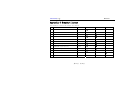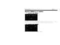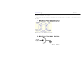
1
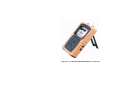
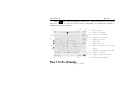
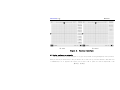
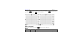
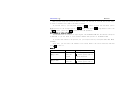
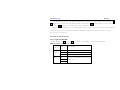
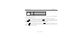
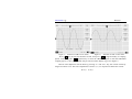
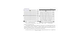
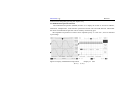
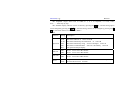
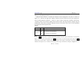
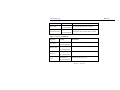
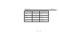
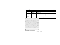
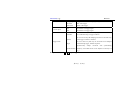
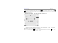
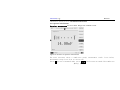
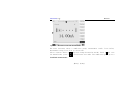
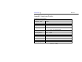
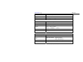
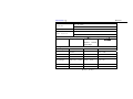
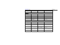
Fan Series Handheld Digital Scopemeter (Oscilloscope)
ZB-2201 Handheld Digital Scopemeter
ZB-2201S Handheld Digital Oscilloscope
User manual
www.aitendo.co.jp
Appearances of ZB-2201S Handheld Digital Oscilloscope
Appearances of ZB-2201 Handheld Digital Scopemeter
Dear user:
Thanks for your choice of Fan Series portable digital Scopemeter(Oscilloscope)
made by us. The Scopemeter(Oscilloscope) serves and accompanies you at any time
tending to offer a swift and high-efficiency work.
The instruction is to introduce systemically you how to use it as well as concerned
notices, please read it carefully prior to use. In this instruction, we provide and cause the
product display consistent with real product as far as possible, if any differential, the
real display of machines will govern.
We assure the Function and specification in accordance with the instructions noticed
which is suitable for Fan Series.
Accompanied with host machine a product warranty card is given. Please fill in it
carefully. We will provide you limited service(such as change , maintain ,
repair)according the content .
Thanks !
Notices
★Make sense of the instructing contents in this Instruction correctly;
★The 4AH lithium polymer battery built in the Scopemeter(Oscilloscope) shall use the
built-in dedicated charger rather than any other charger or DC source adapter to avoid
the occurrence of hazard.
★ Please pay attention to the range of input voltage so as to prevent from the damage of
instrument.
★ Never set the Scopemeter(Oscilloscope) in an unstable stand or table to avoid of a
falling down and subsequently resulting in the damage of products.
★ Never set the Scopemeter(Oscilloscope) nearby the hot body to prevent from damage
of instrument due to superheating.
★ The liquid substance is forbidden to flow into the Scopemeter(Oscilloscope).
★ Never set the Scopemeter(Oscilloscope) under a heavy load.
★ Never use the liquid or gas detergent, but a dry cloth for cleanness is available.
★ Make sure of it is fully charged before a long time in storage, turn off the host
machine you can get a quick charge.
★If the Li-polymer battery need a change, please contact us from the way listed at the
back cover.
Catalogue
Chapter I.......................................................................................................................... 1
1.1 Unpacking for check.......................................................................................... 2
1.2 Introduction to product..................................................................................... 2
1.2.1 Function..................................................................................................... 3
1.2.2 Characteristics .......................................................................................... 3
Chapter II ........................................................................................................................ 4
2.1 Charge................................................................................................................. 5
2.2 Power on ............................................................................................................. 5
2.3 System configure or automatic............................................................... 10
2.3.1 Setup of automatically measured option.................................. 13
2.3.2 Saves setup ........................................................................................ 13
2.3.3 Select or setup of channel.......................................................... 14
2.3.4 Channels run/stop............................................................................... 15
2.4 output of waveform for test................................................................... 16
2.5 power off ....................................................................................................... 16
Chapter III .................................................................................................................... 17
3.1 setup of vertical system ................................................................................... 18
3.2 Setting of horizontal system............................................................................ 22
3.3 Mathematical operation function................................................................... 24
3.4 Automatic measurement function ................................................................ 26
3.5 Save function .................................................................................................... 32
3.6 REF function .................................................................................................... 33
3.7 Trigger function ............................................................................................... 36
Chapter IV..................................................................................................................... 39
4.1 voltage measurement ....................................................................................... 40
4.2 Resistance measurement ................................................................................. 41
4.3 Capacitor measurement .................................................................................. 42
4.4 Make-and-break measurement ...................................................................... 43
4.5 Diode measurement ......................................................................................... 43
4.6 Current measurement ..................................................................................... 44
Appendix ........................................................................................................................ 46
Appendix A main specification ............................................................................. 47
Appendix B Problem and resolutions: ........................................................... 53
Appendix C Standard layout............................................................................. 55
Appendix D Definition of interface............................................................. 56
Appendix E Instruction of the PC software for the Scopemeter....................... 58
www.aitendo.co.jp
Fan Series
Chapter I
Introduction
第1页
共 60 页
www.aitendo.co.jp
Fan Series
1.1 Unpacking for check
As for a new Fan Series portable digital Scopemeter(Oscilloscope), please have a check following the procedures
below:
1.1.1To checks whether or not there exist damage due to transportation.
If any damage happens to packing box or foam protective mattress, please keep it and contact with the salesman.
1.1.2 Check of accessories
The accessories which have been explained in the Instruction Manual shall be checked whether or not they are
missing or damaged, if any, please contact with the salesman.
1.1.3 Check of complete machine
If any damage happens to the appearance of instrument or malfunction occurs, please contact with the salesman.
Please keep the packing if any damage is caused in transportation.
1.2 Introduction to product
Fan Series portable digital Scopemeter(Oscilloscope) is manufactured in accordance with the requirements of
research, development, production, debugging and repair of majority electronic engineers. It integrates the functions
of both oscillograph and multi meter. In contrast to a traditional one,
it has a built-in lithium battery and can work
without an external power supply; it is convenient for moving, especially for in situ application; it has multi trigger
types, including automatic, common and single trigger , capable of locking and subsequently storing the
non-periodicity signals which a traditional one fails to probe; it features compactness, speciously, friendly interface,
equipped with RS-232 lines of communication and PC software which can transfer the waveform to PC machine for
第2页
共 60 页
www.aitendo.co.jp
Fan Series
the purpose of data analysis or compiling into document.
Fan Series portable digital Scopemeter(Oscilloscope) may swift and accurately detect the faults happening to
circuit, serve as an electronic engineer’s right hand, and will surely bring you a great convenience in work.
1.2.1 Function
★ Functions of Scopemeter
★ Fifteen kind of waveform measure directly
★ Function of storage and communication
★ Function of multi meter (only zb2201 has the function)
1.2.2 Characteristics
★ 320×240 high resolution display, larger information capacity, more visually
★ Use a big-capacity lithium battery to supply power; the host machine can be hung; there are multi displacement
means such as supported by a stand, gripped by single hand, convenient for application in various fields.
★ Waveform and waveform parameter can be displayed simultaneously on a screen, 15 parameters can be displayed,
such as max. Value, min. value, means value, mean square root,peak to peak value,periodicity,frequency, positive
pulse width, negative pulse width,rise time,fall time
★ It has an automatic setting function to set automatically time base and amplitude range.
★ To display the menu in Chinese (English), easy to operate
★ It is of compactness(118mm ×200mm ×45mm), and in light weight (host machine < 0.7 kg )
第3页
共 60 页
www.aitendo.co.jp
Fan Series
Chapter II
Fundamental operation for start up/power off
第4页
共 60 页
www.aitendo.co.jp
Fan Series
2.1 Charge
10 hours of charge shall be ensured when it is charging for the first time, after that, 6 hours once is
enough. The host machine shall be power off when charging, (or else it is harmful to the battery).
2.2 Power on
The keyboard for Scopemeter(Oscilloscope) is showed in Figure 1 listed below, the functions
concerned are given in the following table:
CH1
CH2
MATH
REF
↑
←
OFF
→
↓
Trig+
翻页
选项
V
S
存储
测量
mV
mS
背光
菜单
R/S
自动
功能
开/关
Figure 1:Keyboard of Scopemeter
第5页
共 60 页
www.aitendo.co.jp
Fan Series
Keystroke
Function
CH1
Open Channel I
CH2
Open Channel II
MATH
Open Math Display Channel
REF
Open Reference Waveform Channel
OFF
Close display channels above
V、mV
Change vertical amplitude
S、和 mS
Change horizontal time base
存储=Save
Open “SAVE” menu
背光=Backlight
It is allowed to open/close backlight
功能=Function
Capable of displaying function menu
菜单=Menu
To display other setting options
R/S
Run or lock in some waveform
自动=Auto
To automatically display a fit wave-form
开/关=Power on/Power off
To start up/close down host machine
测量=measure
To display measure options
翻页=Page down
used to select menu option
选项=Enter
used to select expected option
Keyboard table of Scopemeter
第6页
共 60 页
www.aitendo.co.jp
Fan Series
Press “ 开/关 ” key to open Scopemeter(Oscilloscope) and the startup interface is first given;
then press any key or wait for several seconds, subsequently, the oscilloscope interface is
automatically given, as in Figure 2.
1.
2.
3.
4.
5.
6.
7.
8.
9.
10.
11.
12.
Figure 2:Interface of Scopemeter
第7页
共 60 页
Run or hold;
Types of trigger
Function interface
Current menu option
Charging status
Time base
Amplitude shift
Opening channel and couple
status
Automaticly measured option
Channel position
Trigger signal position
Grid marks waveform
www.aitendo.co.jp
Fan Series
This interface consists of three sections, the main section refers to the waveform display, the
right section refers to the setting section, the below section refers to the status column.
Waveform display section is involved in the grid, waveform, the needle indicating the
position of waveform, the identification when waveform is at scanning mode as well as the
measurement parameter group the user chose. Every 25 display points produces a grid, the lateral
direction refers to time axis, with range of X s / div , X us / div or X ns / div per grid, while the
longitudinal direction refers to amplitude axis, with range of X V / div , X mV / div per grid.
The arrowhead with number or letter indicates the zero of amplitude of waveform. 1 means the first
channel, and 2 the second channel; M means the channel of calculation valve. R means the reference
waveform channel, the “RUN” or “HOLD” on the above left means the waveform is in scanning
position or has been locked in. The parameters to be measured, as measurement signal’s periodicity,
amplitude, peak value, Root mean square value mean, mean value, can be displayed near to the
bottom of grid in accordance with the selection of user.
The second section is setting section, the input coupling types such as DC, AC , ground,
attenuation multiple of probe, display of positive and negative phases. may arrange by yourself in
accordance with the requirements
The status column tells the channel of measurement, input types of each channel, the
channel selected currently, (the channel selected shall be displayed using reverse color, namely
white foreground against black background, but the unselected shall be displayed normally, namely
第8页
共 60 页
www.aitendo.co.jp
Fan Series
black foreground against white background.), amplitude and arrange of each channel, horizontal
time base, electric quantity of lithium battery as well as current time.
After power on, press the “功能”(function) key to open the function selection interface, as in
Figure 3, and the functions cover oscilloscope, resistance, diode, current, setting, as well as language
options. Pressing “翻页”(Page down) key may change the setting option, while pressing “选
项”(enter)key to perform the function selected. The last option may change the display for language
(Chinese/English) of oscilloscope, and the functions will be presented in the following other text.
第9页
共 60 页
www.aitendo.co.jp
ZB-2201
Fan Series
ZB-2201S
Figure 3: Function interface
2.3 System configure or automatic
The purpose of the system configure is to give an optional setting arranged by user yourself,
Then you can do you work easily. All you need to do is that set up you host machine. And then save
it immediately. So it appears the status you set next time it power on. Such as amplitude, time
第 10 页
共 60 页
www.aitendo.co.jp
Fan Series
Backlight, language, options of measure etc, some is listed below:
Press “菜单”(menu)key to display the menu(figure 4),then press“翻页”(page down)key select
some option you need, press“选项”(enter)to perform it 。
Figure 4:Menu interface
The menu will be displayed by pressing the “菜单”(menu) key, as shown in Table below.
Table 2
Function menu
Option
Description
Time format
Y-T
y-t mode shows the relative relation between vertical voltage and horizontal
第 11 页
共 60 页
www.aitendo.co.jp
Fan Series
time.
X-Y
x-y mode shows the amplitude of Channel 1 on the horizontal axis, and
shows that of Channel 2 on the vertical axis.
Display type
Average
Persist
Grid
Sampling
Language
Vectors
Displayed by
Dots
To display sampling points directly
1、2、4、8、
To set the average sampling time by pressing “Enter” key, from 1 to 64,
16、32、64
advancing by multiples of 2 step by step
On
To open the waveform retaining function
Off
To close the waveform retaining function
On
To display the screen background grid
Off
To close the screen background grid
Real-time
The sampling mode is set as real time sampling
简体中文
English
tie-line between sampling points
To set up the language displayed on the screen
Options set up directly by the key :
Turn on the backlight or turn off the backlight,press the key“背光”(“backlight”);
horizontal shift is controlled by“S”or“mS”;vertical shift is controlled by“V”or“mV”。
Automatically measured option can be select from the Measure Menu, detailed information is listed
below
第 12 页
共 60 页
www.aitendo.co.jp
Fan Series
2.3.1 Setup of automatically measured option
host machine setup the amplitude and the time base automatically, so as to suit for the observation,
when the “自动”(auto)key pressed, it start to schedule.
Options listed below maybe set by the host machine:
Table 3
Function
Setup
Display format
Y-T
vertical“V/div”
Adjustment to a proper division
Vertical division adjustment
Coarse adjustment
Signal inversion
Close
Horizontal position
Center
Horizontal “S/div”
Adjustment to a proper division
Trigger type
Edge
Trigger source
Automatically detect the channel that has signal input.
Trigger level
Midpoint setting
Trigger mode
Automatically
“R/S”:Run or stop waveform sampling.
2.3.2 Saves setup
The method mentioned above can be an easily way to use the host machine.
第 13 页
共 60 页
www.aitendo.co.jp
Fan Series
When you have setup the option you want to setup, you can save it, for the use of next time,
or leave it without save, made it be same as before.
If you want save it, you can press the key “ 存储 ”(save)to enter the save menu, press"
选项"(option) set the storage type as “ 设置 ”(set), then press" 翻页 "(page down)to select the
“ 保存 ”(save), press the " 选项 "(enter)to save the parameter.
2.3.3 Select or setup of channel
The CH1/CH2 means the channel for input signal, and the MATH or REF has the similar conception
as CH1/CH2, so you can think it to be another channel when operate on the MATH or REF.
If you want some channel to be open for you, you can press the key correspond (CH1, CH2, MATH,
and REF).
After that, you can select the channel to be closed, made it the status selected, and then
press OFF to close it.
Table 4
Types of channel
通道 1(CH1)
通道 2(CH2)
status
状态标志
Open
CH1(white against black)
Selected
CH1(black against white)
Closed
Nothing displayed
Open
CH2(white against black)
Selected
CH2(black against white)
第 14 页
共 60 页
www.aitendo.co.jp
Fan Series
数学运算(MATH)
参考波形(REF)
Closed
Nothing displayed
Open
Math(white against black)
Selected
Math(black against white)
Closed
Nothing displayed
Open
Ref(white against black)
Selected
Ref(black against white)
Closed
Nothing displayed
Application of Vertical system (↑ ,
1.
the key
↓,
V and
mV )
↑ or ↓ is set to adjust the vertical position of channel, and the DPI is changed
with the vertical shift.
2.
“V”or“mV”is set to adjust the vertical DPI for all the channel, If the channel is open.
3.
Only the opening channel (namely selected) can be adjust by the key ↑
, ↓ ,V or
mV .
And the waveform of REF is adjust based on the condition it saved.
4.
The information on the left (such as “POS=8”) has the same color of channel, and marked
with “V”, when the vertical system is being adjusted. The unit of MATH is dot at this
time, it is different with other.
2.3.4 Channels run/stop
As a input channel CH1/CH2 samples continuous or stop at the position for a observation, this can
be done by pressing the key R/S or determined by the host machine(if the machine is set to the
第 15 页
共 60 页
www.aitendo.co.jp
Fan Series
trigger mode)
NOTICE:
On the condition that the R/S (run or stop) pressed (namely the machine in the HOLD status), the
vertical system also can be adjusted (zoom in /zoom out) to some extend.
2.4 output of waveform for test
A 1 kHz/1v waveform is provided at the top of the Scopemeter, it is a ring where you can get the
signal easily with the probe. The ground of it is connected with main board, you can have a measure
without extra ground, and it provides a continuously output.
2.5 power off
When you have finished you work, you can power off the machine with the key 开/关 (power off/power
on). When the battery goes out you can use the machine by the charged directly or fully charge the
battery again. But it is better to fully charge the battery, or else it is harmful to the battery.
第 16 页
共 60 页
www.aitendo.co.jp
Fan Series
Chapter III
Function of Scopemeter
第 17 页
共 60 页
www.aitendo.co.jp
Fan Series
On the initial status, the machine displayed as figure 2. or else please press the key “功
能”(function) to enter into the function menu, then press “翻页”(Page down) to select the top,
and press “选项”(enter) to return the initial interface.
Before using the machine, it is better have a setup of the vertical system or the horizontal
system to get a steady and clear waveform, sometimes trigger also need to be have a setup.
You can do it as follows:
3.1 setup of vertical system
3.1.1 Couple of CH1/CH2
Press the key “ CH1 “or” CH2 “to select the channel, it displayed as below,
Table 5 Couple of channel for measure
Function
menu
Couple
Probe
set
description
AC
Without DC parts
DC
All the signal
Ground
Without any signal outside
1X
Set it to the appropriate one as your
10X
probe set
100X
第 18 页
共 60 页
www.aitendo.co.jp
Fan Series
1000X
Invert
ON
Display in an opposite phase
OFF
Display in normal
Press “CH1” or “CH2” key, the system will give the operation menu for “CH1” or “CH2”, the description
concerned please is shown in Table 1:
For instance, the measured signal for CH1 refers to a sinusoidal signal containing direct current biasing.
Press “CH1” key to enter the interface of CH1, then press “翻页” (Page down)key to coupling option, in the end,
press “选项”(option) key to select the AC option so that the AC coupling type is set. The direct-current component
contained in measured signal is obstructed. The waveform display is given in Figure 7
P Press “CH1” key to enter the interface of CH1, then press “翻页” (Page down)key to coupling option, in the
end, press “选项”(option) key to select the DC option so that the DC coupling type is set. All the signal will be get.
The waveform display is given in Figure 8.
第 19 页
共 60 页
www.aitendo.co.jp
Fan Series
Figure 7 :Interface of CH1 on AC status
Figure 8: Interface of CH1 on DC status
Press “CH1” key to enter the interface of CH1, then press “翻页” (Page down)key to coupling
option, in the end, press “选项”(option) key to select the GROUND option so that the GROUND
coupling type is set. No signal outside will get. The waveform display is given in Figure 9.
Vertical scale adjustment will be done by pressing “V” and “mV” key, the vertical sensitivity
ranges from 2mV to 5V. The coarse adjustment is done in 1, 2, 5 in sequence to define the vertical
第 20 页
共 60 页
www.aitendo.co.jp
Fan Series
Figure 9: Couple set to ground
Figure 10:waveform with probe set10:1
scale sensitivity, namely by 2mV、5mV、10mV、20mV、50mV……5V step by step.
Proportion of adjustment probe
Corresponding to the attenuation coefficient, we shall make a corresponding adjustment of the
probe attenuation proportion coefficient in channel operation menu. For example, when the
attenuation coefficient of probe is 10:1, the proportion of input channel of oscilloscope shall be set to
10X so that the scale displayed is consistent with the measures data.
The demonstration given in Figure 10 refers to the setting when the probe of 10:1 is applied and
第 21 页
共 60 页
www.aitendo.co.jp
Fan Series
shall be indicated by vertical scale.
Press “CH1”key to open the CH1 display interface, then press “翻页” (Page down) key to probe
option, and then press “选项”(enter) key to select probe proportion, respectively as 1X, 10X, 100X
and 1000X. Please refer to Table 6.
Table 6
Probe attenuation
coefficient
Setting of
corresponding
menu
1:1
1X
10:1
10X
100:1
100X
1000:1
1000X
3.1.4 Inversion setting of waveform
Waveform in inversion: The signal displayed is relatively inverted to 180 °with electric potential,
as in Figure 10 and Figure 11. Press CH1 key to open CH1 display interface, press 翻页 key to
inversion option, press 选项 key to select the starting up/closing down of inversion.
3.2 Setting of horizontal system
3.2.1 Horizontal control knob
The horizontal control knob can be used to change horizontal time base, the location of current
第 22 页
共 60 页
www.aitendo.co.jp
Fan Series
waveform in memory (memory displacement) and the location of triggering in memory (triggering
displacement). The horizontal center of screen is the time reference point of waveform. The
waveform will expand or contract relative to the screen center, if the horizontal scale is changed. The
change of horizontal position can change the waveform position relative to a trigger point.
Key ← and → : the two keys can be used to adjust the horizontal position of channel
waveform (including mathematical operation). The analysis degree of this control knob changes with
that of the time base.
Key S and mS : the two keys can be used to adjust the main time base, i.e. S/div.
Sign description:
1. “[ ]”represents the position of current waveform window in memory.
2. Arrowheads indicate the position of a trigger point in memory.
3. The horizontal time base (main time base) is indicated in S/div.
Terminology explanation
Y-T mode: in this mode, axis Y shows amplitude, and axis T shows time.
X-Y mode: in this mode, axis X shows the amplitude of Channel 1, and axis Y shows that of
Channel 2.
Operating description
The menu display interface (as shown in Figure 14) can be opened by pressing the “Menu” key,
and the setting option s can be changed by pressing the “翻页” (Page down)key, then the setting
第 23 页
共 60 页
www.aitendo.co.jp
Fan Series
content can be changed by pressing the “Option” key.
3.3 Mathematical operation function
The mathematical operation (MATH) function is to display the results of waveform addition,
subtraction, multiplication, scale and FFT operations between CH1 and CH2 channels. Meanwhile
the results of mathematical operation can be similarly measured by grid.
The amplitude of operation waveform can be adjusted by Key “V” and “mV”, and it is indicated
in percentage.
Figure 12 Display of Mathematical Operation
第 24 页
Display of FFT
共 60 页
www.aitendo.co.jp
Fan Series
The amplitude ranges from 0.1% to 500% in 1, 2, 5 in sequence, i.e. 0.1%, 0.2%,
0.5% ……500% step by step.
The “MATH” display interface can be accessed by pressing theMATHkey, and the setting option
can be changed by pressing the 翻页 key, then the setting content can be changed by pressing the 选
项 key. The menu functions are shown in Table 7.
Table 7
Function
Setting
Description
Operation
A+B
A-B
A*B
A/B
FFT
Waveform addition of source A and B
Waveform obtained by the subtraction of source B
Waveform obtained by using source A multiples source B
Waveform is obtained where source A is divided by source B
FFT spectral analysis display
source A
CH1
CH2
To set
To set
source A as CH1 channel
source A as CH2 channel
source B
CH1
CH2
To set
To set
source B as CH1 channel
source B as CH2 channel
Invert
Open
Close
To open the waveform inversion function for math-metical operation
To close the inversion function
第 25 页
共 60 页
www.aitendo.co.jp
Fan Series
Figure 12-1 FFT Display Interface
When the FFT function is selected, the interface will be displayed in two parts, as shown in
Figure 12-1. Thereof, the upper part displays channel waveform while the lower part displays the
result of FFT frequency spectrum. “ source A” can be used to select FFT channels, and the key
“frequency band” can be used to display all the results of FFT. The high frequency displays the part
of high band, while the low frequency displays the part of low band, in this way, it can be expanded
horizontally for observing the results.
Table 8
Function
Setting
Description
Operation
FFT
FFT spectral analysis display
CH1
To set source A as CH1 channel
CH2
To set source A as CH2 channel
source A
3.4 Automatic measurement function
Press 测量 (measure) key to open the measurement interface where the signal measurement is classified into
Signal 1, Signal 2 and No measurements. Press 翻页 (Page down) key to select the signal option, then press 选项
(Option) key to select Signal 1, Signal 2 and No measurement in turn. Signal 1 and Signal 2 menu will give three
interfaces as in Figure 15, 16, 17 while No measurement menu will give an interface as in Figure 18.Figure 15
第 26 页
共 60 页
www.aitendo.co.jp
Fan Series
Figure 15:Measurement Interface I
Page 1 is shown in Table 9:
Function
Setting
Peak to
Measurement
Peak value
No measurements
Maximum
Minimum
Measurement
No measurements
Measurement
Figure 16 Measurement Interface II
Description
To measure the peak to peak value of signal
To measure the maximum of signal
To measure the minimum of signal
第 27 页
共 60 页
www.aitendo.co.jp
Fan Series
No measurements
Mean value
Root mean square
Measurement
No measurements
Measurement
No measurements
To measure the mean value of signal
To measure the root mean square of signal
Page 2 is shown in Table 10:
Function
Top value
Bottom value
Frequency
Cycle
Setting
Description
Measurement
To measure the top value of signal
No measurements
Measurement
To measure the bottom value of signal
No measurements
Measurement
To measure the signal frequency
No measurements
Measurement
To measure the signal cycle
No measurements
第 28 页
共 60 页
www.aitendo.co.jp
Fan Series
Positive pulse
Measurement
To measure the positive pulse width of signal
width
No measurements
Figure 17 Measurement Interface III
Figure 18 Measurement Interface Ⅳ
Page 3 is shown in Table 11:
Function menu
Setting
Description
第 29 页
共 60 页
www.aitendo.co.jp
Negative pulse width
Delay 1
Delay 2
Rise time
Drop time
Fan Series
Measurement
To measure the negative
No measurements
pulse width of signal
Measurement
To measure the signal
No measurements
delay 1
Measurement
To measure the signal
No measurements
delay 2
Measurement
To measure the rise time
No measurements
of signal
Measurement
To measure the drop
No measurements
time of signal
第 30 页
共 60 页
www.aitendo.co.jp
Fan Series
Figure 19 Measurement Interface Ⅴ
Figure 20
No Signal Measurement Interface
Operating description
The measurement display interface can be accessed by pressing the 测量 key, and the setting option
can be changed by pressing the 翻页 key, then the setting content can be changed by pressing the 选项
key. Attention shall be paid that only three kinds of values can be measured simultaneously, if the
fourth value is selected and measured, the measurement of the first value will be automatically
turned to a situation without measurement.
第 31 页
共 60 页
www.aitendo.co.jp
Fan Series
3.5 Save function
Press the key of “ 保存 ”(save) to open the interface of “SAVE”, as in Figure 21.Select the location
(option to change), then select the save (option to perform), the waveform will be saved.
Figure 21: “SAVE” interface
Refer to Table 12 for display menu.
Function
Type
Setting
Explanation
Waveform
Store or call out the waveform operation
Setting
Store or call out the setting operation
第 32 页
共 60 页
www.aitendo.co.jp
Location
Fan Series
1、2
Designate memory location for saving/calling out waveform /setting data. This
3、4
Scopemeter can store 6 groups of waveform and 1 group of setting, of which two
5、6
channels of waveform
data can be stored synchronously.
Call out
Call out the previously stored waveform /setting from the designated memory location.
Store
Store current waveform /setting in the designated memory location.
Directions:
Location: Designate memory location so as to store waveform, instrument setting or call out the
waveform /setting from an appointed location.
Call out: Scopemeter can call out the stored waveform /setting from the designated memory location.
Storage: Store the current waveform /setting in the designated memory location.
3.6 REF function
During the actual testing process, the failure reason can be determined by using an Scopemeter to
measure and observe the waveform of related subassemblies, and making a comparison between the
waveform and the reference. This approach is more applicable where detailed reference waveforms
for electric circuit action spot are provided.
The reference waveform menu can be displayed by pressing the REF key, as shown in Figure 22, and
the setting description is shown in Table 13.
Table 13
Function
Setting
Description
第 33 页
共 60 页
www.aitendo.co.jp
Storage site
Fan Series
1, 2, 34, 5, 6
To select the waveforms at different storage sits as the reference
Effective
To display whether the current storage site has waveform data for
Ineffective
reference or not
source
CH1
To select Channel 1 of the storage waveform as the reference
selection
CH2
To select Channel 2 of the storage waveform as the reference
On
To set reference waveform to be in Inversion
Off
To close down inversion position
Storage status
Inversion
Figure 22 REF Display Interface
第 34 页
共 60 页
www.aitendo.co.jp
Fan Series
Operating instruction
1. Reference waveform menu can be displayed by pressing the REF key, and the storage site option
can be accessed by pressing the 翻页 key, then the reference waveforms of different storage
sites can be selected by pressing the 选项 key.
2. The storage position option can be accessed by pressing the 翻页 (page down) key, and the
storage position (effective or ineffective) can be selected by pressing the 选项 key.
3. The source selection option can be accessed by pressing the 翻页 key, and the CH1 or CH2
channel of reference waveform can be selected by pressing the 选项 key.
4. The scale of reference waveform can be adjusted to a proper position by pressing the V and mV
keys.
5. The vertical position of reference waveform can be adjusted to a proper position by pressing the
↑ and ↓ keys. ,
Notice:
1. A storage with which the waveform is stored in the mode of X-Y is not applicable to reference
waveform. In the state of REF menu, the storage site is displayed as “ineffective”.
2. The horizontal position and scale can’t be adjusted in the state of reference waveform.
Directions:
1. Location: some specific area for savage of waveform, named 1, 2, 3, 4, 5 and 6.
第 35 页
共 60 页
www.aitendo.co.jp
Fan Series
2. Load: some waveform stored to be restored to the memory from 1, 2, 3, 4, 5, or 6.
3. Save: not only waveform but also parameter can be saved.
4. Data upload: connect the host machine to the pc by a communication line, you can upload the
waveform stored in the host machine, and save it for analysis (BMP format only)
3.7 Trigger function
Trigger function made it possible for observing some waveform, locking it, and displaying it steadily
on the screen. Regular mode for trigger is auto, normal and once. Different mode it acts different,
Auto mode: display a steady waveform when meet the trigger condition or else display a unstable
waveform.
Normal: display the steady waveform that meet the trigger condition.
Once:
display the first steady waveform that meet the trigger condition.
Edge trigger is usual way of trigger. It comes from the comparison between input signal and the
inner compare signal. You can set it the falling side or rising side.
Press the key of Trig+ to open the interface of trigger mode, as in Figure 23.
第 36 页
共 60 页
www.aitendo.co.jp
Fan Series
Figure 23: Trigger System Interface
See table 14 for display explanation menu.
Function
Setting
Description
Edge type
Rising edge
Trigger at rising edge of signal
第 37 页
共 60 页
www.aitendo.co.jp
source option
Fan Series
Falling edge
Trigger can be done at falling edge of signal
PAL field
PAL video trigger
NTSC field
NTSC video trigger
CH1
Set channel 1 as trigger signal
CH2
Set channel 2 as trigger signal
To set in such a way that the sampling waveform is allowable
even when detecting no trigger condition
Automatic
To set in such a way that sampling waveform is allowable only
when trigger condition is satisfied.
General
To set in such a way that only one waveform can be sampled
Trigger mode
when detecting trigger, and then stop there.
Single
Synchronously
Synchronization
waveform
with
synchronizing
frequency of 45-50Hz which can be adjusted via the keys of
“↑↓”.
Here press the keys of ↑
sample
↓to adjust trigger level.
第 38 页
共 60 页
www.aitendo.co.jp
Fan Series
Chapter IV
Multi meter
第 39 页
共 60 页
www.aitendo.co.jp
Fan Series
After power on (namely the initial status) press the 功能 key to enter the function menu, press 翻
页 to select some menu listed on right, then press “portion” to perform the function you selected.
4.1 voltage measurement
Maximum input voltage: 600 Vrms CAT II, 300 Vrms CAT III。
Figure 21 interface of voltage measurement
The main interface shows a simulation graph, measurement result lists below,
measurement range lists left on the bottom.
Select “voltage ”Press “选项”(option) change between DC and AC. Press “V” get into
第 40 页
共 60 页
www.aitendo.co.jp
Fan Series
the manual mode, press “自动” (auto)return auto mode. The simulation graph gives a
visualized measurement.
4.2 Resistance measurement
resistance measurement have six shift: 600Ω、6KΩ、60KΩ、600KΩ、6 MΩ、60 MΩ.
Figure 21 interface of resistance measurement
The main interface shows a simulation graph, measurement result lists below,
measurement range lists left on the bottom.
Press “V” get into the manual mode, press “ 自 动 ” (auto)return auto mode. The
第 41 页
共 60 页
www.aitendo.co.jp
Fan Series
simulation graph gives a visualized measurement
4.3 Capacitor measurement
Capacitor measurement has seven shifts. Range from 6.000nF to 6mF.
Figure 23 interface of capacitor measurement
The main interface shows a simulation graph, measurement result lists below,
measurement range lists left on the bottom.
Press “V” get into the manual mode, press “自动” (auto)return auto mode. The simulation
第 42 页
共 60 页
www.aitendo.co.jp
Fan Series
graph gives a visualized measurement.
4.4 Make-and-break measurement
It measures at the shift 600Ω.
It beep if the result of measurement less than 25Ω.
Figure 25
interface of make-and-break measurement
The main interface shows a simulation graph, measurement result lists below.
4.5 Diode measurement
It shows OL (overload) if the voltage drop is above 2V. And it beeps if the voltage
第 43 页
共 60 页
www.aitendo.co.jp
Fan Series
drop is less 0.25V. The simulation graph gives a visualized measurement.
Figure 24:Interface of diode measurement
The main interface shows a simulation graph, measurement result lists below.
4.6 Current measurement
Current measurement have two shift: 60mA、600mA.
第 44 页
共 60 页
www.aitendo.co.jp
Fan Series
Figure 26:Interface of current measurement
The main interface shows a simulation graph, measurement result lists below,
measurement range lists left on the bottom.
Select “current ”Press “选项”(option) change between DC and AC. Press “V” get into
the manual mode, press “自动” (auto)return auto mode. The simulation graph gives a
visualized measurement.
第 45 页
共 60 页
www.aitendo.co.jp
Fan Series
Appendix
第 46 页
共 60 页
www.aitendo.co.jp
Fan Series
Appendix A main specification
Specification of the Scopemeter
Specification of Scopemeter
Bandwidth(-3dB)
20MHz
Sample
Max sample:80MSa/S
Channels
2
Couple
AC, DC or GROUND
Couple(AC)
< 10 Hz without probe
< 1 Hz 10 MΩ 10:1 passive probe
Rise time
< 17.5 nS
Input independence
1MΩ,≤20pF
Max input voltage
1x CAT III 300 VAC 10x, 100x CAT III 600 VAC
Vertical resolution
8bit
Vertical sensitive
5mV/div-5V/div
Horizontal resolution
50nS/div
Horizontal sensitive
50nS-5S
Depth-sampling
4K/channel
第 47 页
共 60 页
www.aitendo.co.jp
Fan Series
Memory
6 waveform+1parameter
Trigger mode
Auto, normal, once
Trigger type
Edge trigger, video trigger
Basic characteristic
Screen
320×240;backlight
Communication
RS232
Battery
3.7V lithium battery 4AH
Adapter
input:100VAC-240VAC
PC software(showwave.exe)
output:5V±10%DC
1000mA
Size
118mm×200mm×45mm
Weight
690g
Performance of Scopemeter(zb-2201 only)
Measuring range
Input
6000
Max input voltage:
600 Vrms CAT II,
300 Vrms CAT III。
On resistance
25Ω(at the shift of 600Ω), if less it beep
Diode measurement
>2V shows OL(overload)
第 48 页
共 60 页
www.aitendo.co.jp
Fan Series
<0.25 beep
Capacitor measurement
6.000nF- 6mF
Current measurement
60.00mA / 600.0mA (2 shift)
Resistance measurement
600.0Ω- 60.00MΩ
(shift)
600.0mV- 6000V
(5 shift)
Voltage measurement
(7 shifts )
It shows OL if voltage is above 1000v at the shift of 6000V。
Specification:
(running at the temperature 10℃-25 ℃,30 minutes after power on)
Specification of Scopemeter
Vertical system: channels of Scopemeter
Bandwidth(-3dB)
Precision
20MHz
10 mV/div to 20 mV/div: ± 5%
50 mV/div to 5 V/div: ± 3%
offset on vertical (DC)
±0.2 div ±2 mV ±0.5% offset
Trigger sensitivity
DC to20 MHz: 0.8 div
Specification of probe
Rising time
X1
23.3nS
X10 17.5nS
第 49 页
共 60 页
www.aitendo.co.jp
Fan Series
X1
Bandwidth
DC-15MHz
X10 DC-20MHz
Input impedance
X10 10M(without Scopemeter input resistance 1M)
X1 46pF (without input capacitor of Scopemeter)
Input capacitor
X10
15pF more or less
Specification of Scopemeter(zb2201 only) ±(% of reading + % of range)
Function
Range
Tcal± 5 ℃/(year)
Frequency,
measure
current,
load voltage
Voltage
DC Voltage
AC Voltage
600.0 mV
0.3 + 0.08
6.000 V
0.3 + 0.08
60.00 V
0.3 + 0.08
600.0 V
0.3 + 0.08
600.0 mV – 600.0
50 Hz – 1 kHz
1.0 + 0.2
1kHz – 30 kHz
3.0 + 0.2
50 Hz – 1 kHz
1.0 + 0.2
V
AC
+
DC
6.0000 V – 600.0
第 50 页
共 60 页
www.aitendo.co.jp
Voltage
Fan Series
V
1kHz – 30 kHz
3.0 + 0.2
Impedance
600.0Ω
0.5 + 0.2
6.000 KΩ
0.5 + 0.2
60.00 kΩ
0.5 + 0.2
600.0 kΩ
0.5 + 0.2
6.000 MΩ
0.5 + 0.2
60.00 MΩ
1.0 + 0.2
60.00mA
0.5 + 0.2
600.0 mA
0.5 + 0.2
current
DC 电流
AC 电流
60.00mA - 600.0
50 Hz – 1 kHz
1.0 + 0.2
1kHz – 30 kHz
3.0 + 0.2
50 Hz – 1 kHz
1.0 + 0.2
1kHz – 30 kHz
3.0 + 0.2
mA
AC + DC 电流
60.00mA - 600.0
mA
第 51 页
共 60 页
www.aitendo.co.jp
Fan Series
Capacitor
60.00 nF
2.0 + 0.2
600.0 nF
2.0 + 0.2
6000 nF
2.0 + 0.2
60.00 μF
2.0 + 0.2
300.0 μF
2.0 + 0.2
diode
2.000 V
0.5
2.0 + 0.08
mA
Make-and-break
<25Ω,it beep
第 52 页
共 60 页
www.aitendo.co.jp
Fan Series
Appendix B Problem and resolutions:
1.
power on without any response
Mostly it is the battery runs out, charge the battery for a while or fully charge it before use
it again, or else it will not run either. If you can not run it, contact us instead.
2.
Few seconds after power on it closed
Mostly it is the battery runs out, you can power on the host machine again, and have a look at
the symbol of battery at the bottom; if it is not low in battery, charge it immediately
3.
How to change between AC and DC
Press “option” at AC status, enter the DC status;
Press “option” at DC status, enter the AC status.
4.
10 times bigger or smaller than the actual voltage
Have a check of the “probe” sub option of the channel (CH1 OR CH2). Set it to the proper option
such asх10 orх1.
5.
Can not get steady waveform but a vary waveform shows.
Do some operation at the trigger mode;
Have a check of the “signal” sub option of the trigger, set it to the proper channel.
Have a check of the “type” sub option of the trigger, general signal select the edge trigger
and video signal select the video trigger.
第 53 页
共 60 页
www.aitendo.co.jp
Fan Series
Have a try to change the “mode” sub option among auto, normal and once.
6.
Can not communicate with PC
Have a check that the rs232 communication line links the host machine to the pc by COM1 or other,
the software (showwave.exe) is running well on the PC, and have a right configuration such as COM1
or other.
7.
The host machine is power on.
After get the graph of waveform, make sure the “location” is the one you want to be saved.
8.
Baseline drift
When the machine is just power on, without any input signal, the baseline is off the middle
screen (marked 0) quite a lot is the really drift. If the situation happens contact us for a
resolution.
第 54 页
共 60 页
www.aitendo.co.jp
Fan Series
Appendix C Standard layout
The products contain the things list below:
#
description
amount
2201
1
ZB-2201 host machine
1pcs
√
2
ZB-2201S host machine
1pcs
3
20M(10:1)probe
1pair
√
√
4
Communication line
1pcs
√
√
5
PC compact disk
1pcs
√
√
6
《user manual》
1pcs
√
√
7
Specific adapter
1pcs
√
√
8
4000mAHlithium battery
1pcs
√
√
9
《products guarantee card》
1pcs
√
√
10
Probe (for direct measurement)
1pair
√
11
knapsack
1pcs
√
12
100:1probe
1pcs
√
第 55 页
共 60 页
2201S
optional
√
www.aitendo.co.jp
Fan Series
Appendix D Definition of interface
1、 interface for input (ZB-2201)
ZB-2201 interface for input
“CH1” means the first channel, “CH2” means the second channel, “R” means the resistance
or
drop for the diode, “com” means the common, “1V 1KHz” is the signal output for test.
2、 interface for input (ZB-2201S)
第 56 页
共 60 页
voltage
www.aitendo.co.jp
Fan Series
ZB-2201S interface for input
“CH1” means the first channel, “CH2” means the second channel, “1V 1 KHz” is the signal output
for test.
3、 definition of the communication line:
Definition of the communication line
4、 Definition of the adapter interface:
第 57 页
共 60 页
www.aitendo.co.jp
Fan Series
Appendix E Instruction of the PC software for the Scopemeter
Interface of software
“通道一(CH1)、通道二(CH2)”:Show the waveform selected.
“串口号”: Serial port linked. (COM1, COM2, COM3, COM4)
“波形序号”: Waveform selected to upload.
“存储波形”:Save the waveform uploaded as bmp format.
第 58 页
共 60 页
www.aitendo.co.jp
Fan Series
“获取波形”:Upload some waveform stored in the host machine.
Usage:
link the host machine to the pc by the COM1(or others), power on the host machine, run the software
on the
pc(you can get it from the CD), press the button“获取波形”,after get the waveform, save
it(bmp format), all is the process.
Definition of the adapter interface
第 59 页
共 60 页
www.aitendo.co.jp
Fan Series
株式会社秋葉原
http://www.akiba-tech.com
第 60 页
共 60 页