1
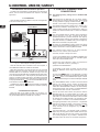
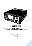
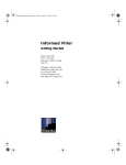
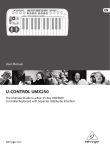
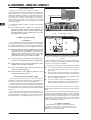
U-CONTROL UMX49/UMX61
1. INTRODUCTION
Thank you for showing your confidence in XXX
products by purchasing the UMX. The UMX is an extremely flexible
master keyboard with a controller unit that can be used for a
wide array of applications. Whether you need independent control
of computer rack synthesizers, General MIDI sound modules or
effects devices, or want to use the UMX for conveniently
operating sequencing software or computer plug-ins—the UMX
offers you tremendous ease of use and allows you to realize
your ideas intuitively.
USB Cable (included)
The UMX49 and UMX61 only differ in the size of the keyboard
(49 or 61 keys).
The following user’s manual is intended to
familiarize you with the unit’s control elements, so
that you can master all the functions. After having
thoroughly read the user’s manual, store it at a safe
place for future reference.
U-CONTROL UMX
Figure 1.1: Power supply via USB
1.1 Before you get started
1.1.1 Shipment
The U-CONTROL was carefully packed at the assembly plant
to assure secure transport. Should the condition of the cardboard
box suggest that damage may have taken place, please inspect
the unit immediately and look for physical indications of damage.
Damaged equipment should NEVER be sent directly
to us. Please inform the dealer from whom you
acquired the unit immediately as well as the
transportation company from which you took
delivery of the unit. Otherwise, all claims for
replacement/repair may be rendered invalid.
To assure optimal protection of your UMX during
transport, we recommend utilizing a carrying case.
Please always use the original packaging to avoid
damage due to storage or shipping.
Figure 1.2: The battery compartment on the bottom side of
the UMX
Open the battery compartment by pressing the shutter clamp
carefully in the direction of the battery compartment, while pulling
the cover of the compartment upwards.
Please note the following points when inserting the batteries:
Never let unsupervised children play with the
device or with its packaging.
V
The +symbol of the batteries must coincide with the +symbol
of the compartment! Incorrect polarity will damage the
electronics!
Please dispose of all packaging materials in an
environment-friendly fashion.
V
Do not mix old and new batteries! When you change the
batteries, always change all 3 batteries at the same time.
V
Do not use damaged batteries. The UMX could be damaged
due to the leakage of chemicals.
V
If you do not use the unit for an extended period of time,
please remove the batteries from the compartment. Here
again, the batteries could leak and damage the device.
1.1.2 Initial operation and power supply
Please make sure that the unit is provided with sufficient
ventilation, and never place the UMX on top of an amplifier or in
the vicinity of a heater to avoid the risk of overheating.
The power supply can be realized in different ways depending
on the main application area. For the installation of the UMX in a
studio environment, it is possible to connect the device directly
to a free USB port of the computer using the USB cable provided
(see Fig. 1.1).
In case it is not possible to establish the power supply over
USB (e.g. because of an overload of the host computer due to
several USB devices connected), it is also possible to operate
the UMX with three 1.5-Volt batteries (type “AA”, see Fig. 1.2).
After inserting the batteries, please close the battery
compartment and make sure the shutter clamp snaps into place
again.
If you neither want to connect the power supply over USB nor
operate the device with batteries, there is yet another possibility
to connect the UMX over an external power supply unit. Please
observe the correct operational data (DC 9 V; 100 mA) and
correct polarity of the connector plug; you will find information
about this above the DC input on the rear of the unit. Reverse
polarity can damage the electronics.
1.1.3 Online registration
Please remember to register your new XXX equipment
right after your purchase by visiting www.XXX.com
(alternatively www.XXX.de) and read the terms and
conditions of our warranty carefully.
4
1. INTRODUCTION
U-CONTROL UMX49/UMX61
Should your XXX product malfunction, our goal is to
have it repaired as quickly as possible. To arrange for warranty
service, please contact the retailer from whom the equipment
was purchased. Should your XXX dealer not be located
in your vicinity, you may directly contact one of our subsidiaries.
Corresponding contact information is included in the original
equipment packaging (Global Contact Information/European
Contact Information). Should your country not be listed, please
contact the distributor nearest to you. A list of distributors can be
found in the support area of our website (www.XXX.com).
V
Remotely controlling groove boxes, step sequencers, MIDI
generators and other “live” software
V
Program changes and volume control on sound generators
(just like on a master keyboard)
V
Can be used by band keyboardists, solo entertainers,
organists, electronic music performers, DJs, sound engineers,
home/project studio owners, theater technicians, etc.
Registering your purchase and equipment with us helps us
process your repair claims quicker and more efficiently.
Remote control is realized by assigning the individual control
elements of the UMX to individual MIDI parameters. Whenever
one of these control elements is operated, the UMX generates
the control data assigned to this control element, which are then
transferred to external devices over a data link. Thus, for
example, the VOLUME/DATA fader is factory-set to send data
controlling the volume level of a channel.
Thank you for your cooperation!
1.2 System requirements
For USB operation, a current WINDOWS® PC or MAC® with a
USB connection is sufficient. Both USB 1.1 and USB 2.0 are
supported.
The UMX supports the USB MIDI compatibility of
WINDOWS® XP and MAC OS® X operating systems.
The UMX can also be operated as a stand-alone MIDI
controller with no PC connected. Software control
via MIDI is also possible, provided your computer
has a MIDI interface.
And how does it work?
The data connection is usually a standard MIDI cable with a
5-pin DIN plug on each end. Such cables should not exceed a
length of 15 meters. With the UMX there is one more data
connection available: the USB cable to the host computer. Here,
the cable should not exceed a length of 5 meters.
The data transmission takes place over 16 channels.
The control data generated by the individual control elements
are also called MIDI messages, which can be divided into 3
major groups:
V
Channel Messages: Here, channel-specific control
information is transmitted. An example of a channel message
is the note-on instruction. As soon as a key is played on the
keyboard of the UMX, the device generates an instruction
which contains the pitch, channel number and velocity. The
receiving sound generator “knows” which tone has to be
played.
V
System Messages: These messages are not channelspecific but relate to the entire system to which they are
sent. They are divided into 3 groups: System Exclusive
Messages (for operating system backup, updates, management
of memory contents); System Real-Time Messages (e.g. for
remote control of other devices); System Common Messages
(e.g. for the synchronization of several devices).
V
Control Messages: Also known as Control Changes or
Controllers, abbreviated as “CC… (controller number)”.
There are 128 controllers in total, which are numbered
from 0 to 127.
2. INTRODUCTION TO MIDI
2.1 MIDI control for beginners
Application possibilities for the UMX models are truly wideranging. We’ll start with a couple of general explanations and
examples that should quickly let you get a good understanding of
MIDI basics.
The definition of the MIDI standard began in 1982 with the
cooperation of various international companies (MIDI: Musical
Instrument Digital Interface). At that time, musicians were looking
for a possibility of managing the communication of electronic
musical instruments of different makes with one another.
What exactly does the UMX do?
Simply put, this a remote control for all kinds of MIDI equipment.
Using the faders, rotary knobs and buttons, the foot pedal and
the keyboard, an entire array of control instructions can be
generated, which in turn can control the most diverse functions
of external devices.
What kinds of equipment can I control with the UMX?
You can basically control any device supporting the MIDI format.
Both hardware and software MIDI devices are controlled in exactly
the same way. The only difference is in the wiring.
Here are a couple of suggestions on how you can use your
UMX:
V
Editing sound parameters of (virtual) synthesizers, sound
samplers, GM/GS/XG sound generators
V
Controlling parameters on effects equipment/software plugins such as effects processors, reverbs, compressors,
equalizers
V
Remotely controlling software mixers (volume, panorama,
mute functions, etc.)
V
Remotely controlling transport functions (playback, forward,
stop, etc.) on sequencers, hard disk recorders, drum computers,
etc.
V
Live control of volume and sound parameters on expanders
Please refer to Table 6.1 to find out which type of
controller you are currently working with.
MIDI data are only control data and contain no audible
audio information! The data transmission takes
place over 16 channels.
What settings do I have to make? Where? How?
Basically, which control element generates which controller
must be set on the UMX, and how incoming controller commands
should be interpreted must be set on the receiving device.
Regarding controller assignment, there are two possible
principles:
V
You use the preset controller configuration set in the
factory (see Fig. 3.1). In this case, you only need to make
the assignments on the receiving device.
V
You use your own controller configuration set up in ASSIGN
mode. How to assign controllers to the UMX is described in
Chapter 4 “Operation”.
2. INTRODUCTION TO MIDI
5
U-CONTROL UMX49/UMX61
3. CONTROL ELEMENTS AND
CONNECTIONS
2.2 USB mode and stand-alone operation
The UMX can be operated as a USB interface or stand-alone
device. The two modes are different with respect to the MIDI
signal flow.
2.2.1 USB mode
When the UMX is linked via USB to a computer, the signal flow
is as shown below (Fig. 2.1).
Sound-Modul
VOLUME
MUTE
DEMO
FILTER
LEVEL
PHONES
PROG
TYPE
COMBI
PLAY
POWER
The following factory settings refer to GLOBAL MIDI
channel 1.
The keyboard of the UMX has 49 or 61 large, velocitysensitive keys for maximum playing comfort. The keyboard
as an
not only provides for playing, but also functions
encoder in the context of the assignment procedure.
The MODULATION wheel is factory-set to function as a
conventional modulation wheel (MIDI CC 1). In ASSIGN
mode, any MIDI controller can be assigned to it. When you
release the MODULATION wheel, it retains its adjusted
value.
The PITCH BEND wheel is normally used to change the
pitch in real time. In this way, a sound can be “bent”
upwards/downwards by several semitones while playing.
As a default factory setting, pitch bending is assigned to
this wheel. However, in ASSIGN mode you can assign any
MIDI control command to the pitch wheel.
IN
OUT
(intern)
Ex works, the VOLUME/DATA fader controls the volume
of the notes played on the keyboard (MIDI CC 7). In ASSIGN
mode, it can be set to control any MIDI controller.
MIDI
USB
ON
OFF
The ASSIGN button allows you to assign different
functions to the various control elements.
The basic principle is always the same:
(intern)
Fig. 2.1: Block diagram of MIDI signal flow
After the UMX has been connected to the host computer, a
virtual MIDI IN and MIDI OUT interface is emulated.
MIDI data generated in the UMX are first sent over the USB
interface to the host computer, where they are received at the
emulated MIDI IN. A sequencer software running on the host
computer receives the MIDI data via the MIDI IN and relays them
to the emulated MIDI OUT—if all sequencer parameters are set
properly. The data are then sent back to the UMX via the USB
interfaces on the computer/UMX, where they are looped through
to the physical MIDI OUT (
). From here, the MIDI data are sent
to the devices connected to the MIDI OUT.
The MIDI OUT connector
can also be used as a normal MIDI
interface, independently of the sequencer software operating
the UMX.
2.2.2 Stand-alone operation
When the UMX is not linked via USB to a computer, it is
automatically set to stand-alone mode. In this case, the UMX can
only send out MIDI data from its MIDI OUT connector.
1) Press the ASSIGN button and keep it pressed. The
status LED above the button lights up. The UMX signals
that it has entered ASSIGN mode.
2) Select the control element to which you would like to
assign a new MIDI function by operating it.
3) Release the ASSIGN button.
4) Depending on the choice you made, you may have to
define an additional value range (see below for more
details).
5) Press the
-button on the keyboard to confirm
your assignments. To discard your assignments either press
the
-button or the ASSIGN button again. In either
case, the ASSIGN LED goes out and the UMX quits ASSIGN
mode.
The USER MEMORY button is used to recall the internal
memory. The internal memory contains all assignment
information set in ASSIGN mode. Any changes that were
made after USER MEMORY selection are automatically
saved without further user prompts. The USER MEMORY
is retained even after the unit is switched off.
The two OCTAVE SHIFT buttons are preset to shift the
keyboard range by up to three octaves up or down. The
associated LEDs help you identify the current octave setting
(see Table 3.1). Since the OCTAVE SHIFT buttons can also
be assigned to any MIDI controller, we would like to refer
you to Chapters 4.2.8 and 4.2.9 for detailed information.
The eight high-resolution rotary controls R1 – R8 generate
continuous controller information. They are the controllers
that are shown above the buttons in the table
. All
rotary controllers can be assigned to any controller in
ASSIGN mode.
The eight buttons B1 – B8 generate switch controllers.
Again, they are assigned to various default functions (see
table on the device). Like the rotary controls, the buttons
can be freely assigned to any controller in ASSIGN mode.
The table shows the factory-set controller assignments.
6
3. CONTROL ELEMENTS AND CONNECTIONS