1
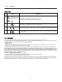
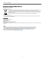
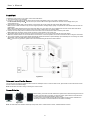
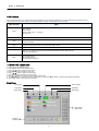
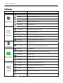
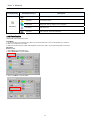
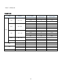
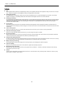
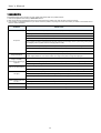
FP2202CHB MEDICAL DISPLAY USER S MANUAL 2MP High Bright Color U s er ’ s Ma n u al IMPORTANT SAFETY INSTRUCTIONS 2 WARNING AND CAUTION EXPLANATION OF GRAPHICAL SYMBOLS SAFETY LOGO FCC INFORMATION MANUFACTURER S RECYCLING AND ENERGY INFORMATION CLASSIFICATION 2 2 3 3 4 4 QUICK START 5 RAISE AND LOWER MONITOR SCREEN SCREEN ROTATION TILT AND SWIVEL MONITOR SCREEN PACKAGE CONTENTS 5 5 6 6 OSD CONTROLS 7 TO MAKE OSD ADJUSTMENTS MAIN MENU OSD FUNCTION LOCK MODE EXPLAIN 7 7 8 9 HOT KEY CONTROLS 11 RECOMMENDED USE 12 CLEANING 13 PRODUCT SPECIFICATIONS 14 SPECIFICATIONS DISPLAY MODE EXTERNAL CONNECTIONS (OPTION) 14 15 15 FEATURES 16 TROUBLESHOOTING 17 1 U s er ’ s Ma n u al IMPORTANT SAFETY INSTRUCTIONS Warning and Caution Warning To prevent fire or shock hazards, do not expose this unit to rain or moisture. Also, do not use this unit’s polarized plug with an extension cord receptacle or other outlets unless the prongs can be fully inserted. Refrain from opening the cabinet as there are high voltage components inside. Refer servicing to qualified service personnel. Caution To reduce the risk of electric shock, make sure power cord is unplugged from wall socket. To fully disengage the power to the unit, please disconnect the power cord from the ac outlet. Do not remove cover (or back). No user serviceable parts inside. Refer servicing to qualified service personnel. Caution Medical Display is intended to use in displaying images for review and analysis by trained medical practitioner for diagnose in CT, MRI, HIS and PACS. This device is not suitable for a digital mammography system. Grounding reliability can only be achieved when the equipment is connected to an equivalent receptacle marked “Hospital Only” or “Hospital Grade”. This device is intended to use (1) outside the “patient vicinity” area or (2) within the “patient vicinity” to the patient such as consulting rooms. That SIP/SOPs need to be connected properly and that any unused SIP/SOPs shall not be accessible for the patient to contact in the patient area after the LCD is integrated into a medical system. Caution To prevent electric shock, please do not remove cover or any internal components. Refer to a qualified technician for service. Unplug the monitor from the power outlet before cleaning. Use a damp cloth. Please follow the national guidelines for unit disposal. This product can not be used for a life-support system. The unit is for exclusive interconnection with IEC 60XXX certified equipment outside of patient environment and IEC 60601-1 certified equipment inside the patient environment. This device comply with EN60601-1-2, to minimize the interference from other equipment, a minimum 0.5 m distance shall be kept form other potential electromagnetic sources, such as the Cell Phone. To have best performance for this product, it's recommended to replace panel after 5 years of usage. "This product fulfils the Class A limits. This monitor cannot be used in buildings shared by many residents or companies. It must have a distance of 30 m to the boundaries to the premises of the enterprise using this monitor." Contact Information: RICHARDSON ELECTRONICS Display Systems Group th 12975 16 Ave. N., Suite 300 Plymouth, MN 55441 Sales: 888-735-7373 TEKLINK Technical Support: www.teklink.rell.com www.imagesystemscorp.com Explanation of Graphical Symbols This symbol warns user that un-insulated voltage within the unit may have sufficient magnitude to cause electric shock. Therefore, it is dangerous to make any kind of contact with any part inside this unit. This symbol alerts the user that important literature concerning the operation and maintenance of this unit has been included. Therefore, it should be read carefully in order to avoid any problems. Main switch ON Main switch OFF Protective earth terminal marked DC Input When operating the Medical Display with a 220-240V AC power source in Europe, use the power cord provided with the monitor. In the UK, a BS approved power cord with a moulded plug has a Black (five Amps) fuse installed for use with this equipment. If a power cord is not supplied with this equipment please contact your supplier. When operating the Medical Display with a 220-240V AC power source in Australia, use the power cord provided with the monitor. If a power cord is not supplied with this equipment please contact your supplier. For all other cases, use a power cord that matches the AC voltage of the power outlet and has been approved by and complies with the safety standard of your particular country. 2 U s er ’ s Ma n u al Safety Logo No. Logo Description 1 Authentication sign of Standard Inspection Bureau for U.S.A. Complies with UL 60601-1 AND CAN/CSA C22.2 NO. 601.1 2 Authentication sign of Standard Inspection Bureau for Canadian and U.S.A safety standard at the same time. Complies with UL60950, CAN/CSA-C22-2 N60950-1-F03. 3 The LCD monitor complies with the 93/42/EEC, EN60601-1, EN60601-2 of related European standards. 4 We hereby declare that the equipment specified above conforms to the technical standards as specified in the FCC Rules. FCC Information Use the attached specified cables with the Medical Display so as not to interfere with radio and television reception. 1. The power supply cord you use must have been approved by and comply with the safety standards of U.S.A., and meet the following condition. Power supply cord:Non shield type, 3-conductor, Hospital Grade Plug Length:2.0m Plug shape:U.S.A 2. Please use the supplied shielded video signal cable, 15-pin mini D-SUB to DVI-A cable or DVI-D to DVI-D cable. Use of other cables and adapters may cause interference with radio and television reception. This equipment has been tested and found to comply with the limits for a Class A digital device, pursuant to part 15 of the FCC Rules. These limits are designed to provide reasonable protection against harmful interference in a residential installation. This equipment generates, uses, and can radiate radio frequency energy, and, if not installed and used in accordance with the instructions, may cause harmful interference to radio communications. However, there is no guarantee that interference will not occur in a particular installation. If this equipment does cause harmful interference to radio or television reception, which can be determined by turning the equipment off and on, the user is encouraged to try to correct the interference by one or more of the following measures: 1. Reorient or relocate the receiving antenna. 2. Increase the separation between the equipment and receiver. 3. Connect the equipment into an outlet on a circuit different from that to which the receiver is connected. 4. Consult your dealer or an experienced radio/TV technician for help. If necessary, the user should contact the dealer or an experienced radio/television technician for additional suggestions. The user may find the following booklet, prepared by the Federal Communications Commission, helpful: “How to Identify and Resolve Radio-TV Interference Problems.” This booklet is available from the U.S. Government Printing Office, Washington, D.C., 20402, Stock No. 004-000-00345-4. 3 U s er ’ s Ma n u al Manufacturer s Recycling and Energy Information Disposing of your old product Within the European Union EU-wide legislation, as implemented in each Member State, requires that waste electrical and electronic products carrying the mark (left) must be disposed of separately from normal household waste. This includes monitors and electrical accessories, such as signal cables or power cords. When you need to dispose of your display products, please follow the guidance of your local authority, or ask the shop where you purchased the product, or if applicable, follow any agreements made between yourself. The mark on electrical and electronic products only applies to the current European Union Member States. Outside the European Union If you wish to dispose of used electrical and electronic products outside the European Union, please contact your local authority so as to comply with the correct disposal method. Classification Power by Class I power supply SKYNET, SNP-A127-M No Applied Part. No protection against the ingress of water: IPX0 Mode of operation: Continuous Operation The equipment not suitable for use in the presence of a flammable anesthetic mixture with air or with oxygen or nitrous oxide: Not AP or APG Category: 4 U s er ’ s Ma n u al Quick Start To attach the LCD monitor to your system, follow these instructions: 1. Turn off the power to your computer. 2. For the PC:Connect the DVI signal cable to the connector of the display card in your system. Tighten all screws. For the PC with Analog output:Connect the 15-pin mini D-SUB to DVI-A signal cable to the connector of the display card in your system(Figure A-01). 3. Connect the DVI signal cable to the connector on the back of the monitor. Place the video signal cable (Figure A-01). Note: Incorrect cable connections may result in irregular operation, damage display quality / components of LCD module and/or shorten the module’s life. Note: Collect cables and keep them in the stand with cable cover. The cable cover can be attached on the front or back side of Tilt Stand. Please check Tilt, Rise and Lower monitor screen and screen rotation when you manage cables. 4. Connect one end of the power cord to the AC inlet on the back of the monitor and the other end to the power outlet. Note: Please refer to Caution section of this manual for proper selection of AC power cord. 5. The Vacation Switch on the left side of the monitor must be turned on. Turn on the monitor with the front power button. Note: The Vacation Switch is a true on/off switch. If this switch is on the OFF position, the monitor cannot be turned on using the front button. 6. Turn on the computer. No-touch Auto Adjust automatically adjusts the monitor to optimal settings upon initial setup for most timing. For further adjustments, refer to the OSD section of this User’s Manual. Note:If you have any questions, please refer to the Troubleshooting section of this User’s Manual. Figure A-01 Raise and Lower Monitor Screen The monitor may be raised or lowered in either Portrait or Landscape mode. To raise or lower screen, place hands on each side of the monitor and lift or lower to the desired height. Note: Handle with care when raising or lowering the monitor screen. Screen Rotation Before rotating, the screen must be raised to the highest level to avoid knocking the screen on the desk or pinching with your fingers. To raise the screen, place hands on each side of the monitor and lift up to the highest position (Figure A-02). To rotate screen, place hands on each side of the monitor screen and turn clockwise from Landscape to Portrait or counterclockwise from Portrait to Landscape. Figure A-02 Note: To rotate OSD menu between landscape and portrait, refer to “OSD Controls” section, “OSD ROTATION” function. 5 U s er ’ s Ma n u al Tilt and Swivel Monitor Screen Figure A-04 Figure A-03 Tilt Swivel Grasp top and bottom sides of the monitor screen with your hands and adjust the tilt as desired. Grasp both sides of the monitor screen with your hands and adjust the swivel as desired. Note: If the screen is rotated counterclockwise, the tilt function is not available. Note: Handle with care when tilting the monitor screen Package Contents Included with your LCD monitor are following items: 1pcs DVI Cable 1pcs 1pcs 1pcs Power Cord User ‘s Manual (CD-ROM) Quick Setup 6 U s er ’ s Ma n u al OSD Controls Your LCD monitor allows you to easily adjust the characteristics of the image being displayed. All of these adjustments are made using the control buttons on the monitor. While you use these buttons to controls, an OSD shows you their change. Main Function Menu Power Power Indicator: Green: Normal Orange: Power Saving 、No Signal Off: Power Off Source Input source selection*. Auto Automatically adjusts the Image Position and H. size (or V. size) setting and Fine Settings. Mode items selection.* Enter Access and control the function of sub-menu when OSD is shown. > Press the “>” to selection sub-menu items and increase adjustment when OSD is shown. < Press the “<” to selection sub-menu items and decrease adjustment when OSD is shown. Quick mode item selection. Menu Start the OSD feature. Exits the OSD controls. Exits to the OSD main menu. *Refer to the Hot Key Controls section. To Make OSD Adjustments 1. Power on the LCD Medical Display. 2. Press “Menu” button to start the OSD menu. 3. Press “>, <” button to select the menu items. 4. Press “Enter” button to enter the menu item. 5. Press “>, <” button to select sub-menu items. 6. Press “Enter” button to enter the sub-menu item. 7. Press“>, <”button to change the current setting of the function. 8. To exit the OSD menu or go back to the previous action by clicking the ”Menu” button. It will save the change automatically. 9. Press “Auto” button to process auto tune function. Main Menu Color Menu Advance Menu Image Menu OSD Menu Display Menu Setup Menu Display Menu Brightness Saturation Contrast Black Level OSD Control Button State Hue Operation Explaining 7 U s er ’ s Ma n u al OSD Function Primary Directory Display Menu Secondary Directory Description Brightness Adjust the brightness of the screen. Contrast Adjust the contrast of the image. Hue Adjust the purity and depth of the red, blue, green of color. Saturation Adjusts the Saturation of the color Black Level Adjust the black level. Auto Adjust Automatically adjust image Clock, Phase, H-Position, V-Position settings Auto Balance Automatically adjust color of the image. Phase Adjust the focus of the image. Clock Adjusts the clock pulse of the image. H-Position Move the image left and right on the screen. V-Position Move the image up and down on the screen. Gamma Adjusts Gamma value. Color Temp. Change the color intensity of the temperature selected Scaling Adjust Image size. Zoom Mode Change the screen size according to the image aspect ratio. Start Screen On/Off start screen. Auto Mode On/Off Auto Adjust. LED Mode On/Off LED function. H-Position Moves the OSD left and right on the screen. V-Position Moves the OSD up and down on the screen. Rotation Rotations the OSD. Time Out Adjusts OSD display time setting. Language Choose language of the display on the screen. Image Menu Color Menu Advanced Menu OSD Menu 8 U s er ’ s Ma n u al Primary Directory Secondary Directory Description All Reset Recall the all factory default settings. Lock Mode Lock the OSD function. Overlapped Setting Value when the image to occur overlapped. DVI Select Select DVI source. Information Shows Firmware, Source and Resolution. Setup Menu Lock Mode Explain FP2202CHB system default value is Off. Lock Mode 1. Off: Function keys are non-locked, press “Menu” key to start the OSD menu and you can adjustment any functions. 2. Mode 1: All function keys are locked. 3. Mode 2: All function keys are locked unless brightness control. Press “Menu” key to start the brightness control menu. Operation How To Lock 1. Press “Menu” key to start OSD menu. 2. Select “Setup Menu” and press “Enter”. Setup Menu All Reset DVI Select Lock Mode Information Overlapped 3. Select “Lock Mode” and press “Enter”. Setup Menu All Reset DVI Select Lock Mode Information Overlapped 9 U s er ’ s Ma n u al 4. Select the Lock Mode and press “Enter” will save the setting value automatically. Setup Menu Lock Mode Off Mode 1 Mode 2 5. Press “Menu” button and exit OSD menu. If you setting in “Off” mode, press “Menu” button will shows the image: Display Menu Brightness Saturation Contrast Black Level Hue If you setting in “Mode 1” mode, press “Menu” button will shows the image: If you setting in “Mode 2” mode, press “Menu” button will shows the image: Brightness 75 How To Unlock If you setting in “Mode 1” or “Mode 2” and you want to unlock, please hold the left key “<” (the button on back of the monitor) until shows message “key unlocked” on the screen, lock function will be removed. Note: If you have used methods as above to remove lock function, it will be locked again when you not use OSD function after 15 minutes. Note: You must be set in “Off” mode could remove lock function forever, and will not be locked automatically again. 10 U s er ’ s Ma n u al Hot Key Controls The Hot Key function allows the user to easily adjust the display to the desired requirements. The operation is not in OSD controls and single-click the hot key function button, and you can start hot key function. 1. Input Source Selection Press “Source” button to select the input source. DVI-A VGA DVI-D VGA: Acquire analog signal from the D-sub connector. DVI-A: Acquire analog signal from the DVI-I connector. DVI-D: Acquire digital signal from the DVI-I connector. 2. Mode item Selection Press “Auto” button, you can select color on the front of the screen of display. User Mode DICOM Mode LB Mode CL Mode BL Mode User Mode: User identify the standard display operation. DICOM Mode: System set the DICOM standard operation. CL Mode: To imitate the display output color temperature of about 6500k. BL Mode: To imitate the display output color temperature of about 9300k. LB Mode: To imitate the operation for whitelight lampbox. 3. Gamma item Selection Press” >”(right) button and select Gamma value Native Gamma 1.8 Gamma 2.0 User DICOM Gamma 2.2 Native: Default. Gamma 1.8: The display state is 1.8 for gamma value. Gamma 2.0: The display state is 2.0 for gamma value. Gamma 2.2: The display state is 2.2 for gamma value. DICOM: The display state is standard for DICOM. User: The display state is by oneself set for gamma value. 11 U s er ’ s Ma n u al Recommended Use For optimum performance, please note the following when setting up and using the multisync LCD monitor: Do not open the monitor. There are no user serviceable parts inside and opening or removing covers may expose you to dangerous shock hazards or other risks. Refer all servicing to qualified service personnel. Do not spill any liquids into the cabinet or use your monitor near water. Do not insert objects of any kind into the cabinet slots, as they may touch dangerous voltage points, which can be harmful or fatal or may cause electric shock, fire or equipment failure. Do not place any heavy objects on the power cord. Damage to the cord may cause shock or fire. Do not place this product on a sloping or unstable cart, stand or table, as the monitor may fall, causing serious damage to the monitor. Do not place any objects onto the monitor and do not use the monitor outdoors. The inside of the fluorescent tube located within the LCD monitor contains mercury. Please follow the bylaws or rules of your municipality to dispose of the tube properly. Immediately unplug your monitor from the wall outlet and refer servicing to qualified service personnel under the following conditions: When the power supply cord or plug is damaged. If liquid has been spilled, or objects have fallen into the monitor. If the monitor has been exposed to rain or water. If the monitor has been dropped or the cabinet damaged. If the monitor does not operate normally by following operating instructions. Do not bend power cord. Do not use monitor in high temperature, humid, dusty, or oily areas. Do not cover vent on monitor. If monitor or glass is broken, do not come in contact with the liquid crystal and handle with care. Caution Allow adequate ventilation around the monitor so that heat can properly dissipate. Do not block ventilated openings or place the monitor near a radiator or other heat sources. Do not put anything on top of monitor. The power cable connector is the primary means of detaching the system from the power supply. The monitor should be installed close to a power outlet, which is easily accessible. Handle with care when transporting. Save packaging for transporting. Image persistence is when a residual or “ghost” image of a previous image remains visible on the screen. LCD monitors’ image persistence is not permanent, but constant images being displayed for a long period of time should be avoided. To alleviate image persistence, turn off the monitor for as long as the previous image was displayed. For example, if an image was on the monitor for one hour and a residual image remains, the monitor should be turned off for one hour to erase the image. Correct placement and adjustment of the monitor can reduce eye, shoulder and neck fatigue. Check the following when you position the monitor: For optimum performance, allow 20 minutes for warm-up. Adjust the monitor height so that the top of the screen is at or slightly below eye level. Your eyes should look slightly downward when viewing the middle of the screen. Position your monitor no closer than 40 cm and no further away than 70 cm from your eyes. The optimal distance is 50 cm. Rest your eyes periodically by focusing on an object at least 50 cm away. If reflected light makes it hard for you to see your screen, use an anti-glare filter. Adjust the monitor’s brightness and contrast controls to enhance readability. Use a document holder placed close to the screen. Avoid displaying fixed patterns on the monitor for long periods of time to avoid image persistence (after-image effects). Get regular eye checkups. Ergonomics To realize the maximum ergonomics benefits, we recommend the following: Adjust the backlight to best state. Do not position the Contrast control to its maximum setting. Use the preset Size and Position controls with standard signals. Use the preset Color Setting. Do not use primary color blue on a dark background, as it is difficult to see and may produce eye fatigue to insufficient contrast. 12 U s er ’ s Ma n u al CLEANING WARNING If you dropped any material or liquid such as water onto the monitor when cleaning, unplug the power cable immediately and contact your dealer or the nearest service center. Always make sure your hands are dry when unplugging the power cable. CAUTION For safety reasons, turn-off the power switch and unplug the monitor before cleaning. Do not scratch or rub the screen with a hard object. Never use any of the following solvents on the Medical Display. Harsh chemicals may cause damage to the cabinet and the touch sensor. Thinner Spray-type cleaner, Benzene, Wax, Abrasive cleaner, Acid or Alkaline solvent CABINET ․ Remove dirt with a lightly moistened cloth and a mild solvent detergent. Then wipe the cabinet with a soft dry cloth. 13 U s er ’ s Ma n u al Product Specifications Specifications Model FP2202CHB Specifications Panel LCD Display TFT LCD IPS Color Characteristics Active screen size 54cm(21.3 inches) 0.270(H) × 0.270(V)mm Pixel Pitch Pixel Format 1600×1200 / 1200×1600 Viewing Angle (Horizontal) 170degrees@CR>=10 Viewing Angle (Vertical) 170degrees@CR>=10 True 8-bit and can simulate to 10-bit Display Colors Adapter Power Input 12V, 9A, 108W Environment Operating Temperature +10℃ ~ +35℃ Conditions Storage/Transportation Temperature Operation Relative Humidity Storage/Transportation Relative Humidity -20℃ ~ +60℃ 30% ~75% Non-Condensing 10% ~95% Non-Condensing Atmospheric pressure Mechanical Dimensions Packaging 500~1060 hPa Width/ Width without Stand 474 / 474mm Height/ Height without stand Depth / Depth without stand Monitor Weight / Weight without stand 455 / 380 mm 252 / 103 mm 11.3 / 7.4 kg Packaging Specification The “Top Level Assembly” shall meet the Packaging Specification. Ink The ink shall not rub off after a suitable drying time. Multiple Trips The carton shall withstand 10 trips by any combination of air, rail, land, or sea transportation. Shipping Carton Type Sensor Device Ambient Sensor One Piece Construction Detects environment light. Front Sensor Detects Panel Luminance Backlight Sensor Detects internal Panel Luminance Luminance Calibration: Software Default Gamma: 1.8,2.0,2.2 DICOM part 14 14 U s er ’ s Ma n u al Display Mode Mode Resolution VGA SVGA 640 × 480 Dot Clock (MHZ) Vertical Scanning Frequency (Hz) Horizontal Scanning Frequency (kHz) 31.50 73 37.86 31.50 75 37.50 36.00 85 43.26 36.00 56 35.16 50.00 72 48.08 49.50 75 46.88 56.25 85 53.67 75.00 70 56.48 75.00 72 57.87 78.75 75 60.02 94.5 85 68.67 108.0 60 63.98 135.0 75 79.98 800 × 600 VESA XGA SXGA UXGA 1024 × 768 1280 × 1024 1600 × 1200 162.0 60.00 60.00 832 x 624 57.28 75 49.73 1152 × 870 100.00 75 68.68 640 × 480 25.18 60 31.47 700 × 400 28.32 70 31.47 1152 × 900 105.59 76 71.73 MAC VGA SUN 15 U s er ’ s Ma n u al Features DVI The integrated interface ratified by the Digital Display Working Group (DDWG) that allows both digital and analog connectors off of one port. The “I” stands for integration for both digital and analog. The digital portion is DVI based. DFP (Digital Flat Panel) An all-digital interface for flat panel monitors which is signal compatible with DVI. As a DVI-based digital only connection, only a simple adapter is necessary for compatibility between DFP and other DVI-based digital connectors such as DVI and P&D. P&D (Plug and Display) The VESA standard for digital flat panel monitor interfaces. It is more robust than DFP since it allows for other options off a signal connector (options like USB, analog video and IEEE-1394-995). The VESA committee has recognized that DFP is a subset of P&D. As a DVI-based connector (for the digital input pins), only a simple adapter is necessary for compatibility between P&D and other DVI-based digital connector such as DVI and DFP. Pivoting Stand Allows users to adjust the monitor to the orientation that best fits their application, either Landscape orientation for wide documents, or portrait orientation for the ability to preview a full page on one screen at one time. The Portrait orientation is also perfect for full screen video conferencing. Color Control Systems Allows you to adjust the colors on your screen and customize the color accuracy of your monitor to a variety of standards. OSD (On-Screen Display) Controls Allow you to quickly and easily adjust all elements of your screen image via simple to use OSD. Ergo Design Features Enhance human ergonomics to improve the working environment, protect the health of the user and save money. Examples include OSD controls for quick and easy image adjustments, tilt base for preferred angle of vision. Intelligent Power Manager System Provides innovative power-saving methods that allow the monitor to shift to a lower power consumption level when on but not in use, saving of your monitor energy costs, reducing emissions and lowering the air conditioning costs of the workplace. Multiple Frequency Technology Automatically adjusts monitor to the display card’s scanning frequency, thus displaying the resolution required. FullScan Capability Allow you to use the entire screen area in most resolutions, significantly expanding image size. Wide Viewing Angle Technology Allows the user to be able to see the monitor from any angle from any orientation — Portrait or Landscape. Provides the same viewing angles either up, down, left or right. Gamma Internal circuitry automatically converts 8-bit data from the PC to 10-bit and back to 8-bit, producing smooth. Gamma can be set by using preset values or creating a custom setting. 16 U s er ’ s Ma n u al Troubleshooting If the Medical Display fails to function correctly, please follow these steps for a possible solution. 1. Perform the adjustments according to Quick Start section. 2. Refer to the following troubleshooting chart if you cannot resolve the problem from other sections of this Users Guide. 3. If the problem is not described below or you cannot correct the problem, stop using the monitor and contact your dealer or the nearest service center for further assistance. Problem Check to see The signal cable should be completely connected to the display card/computer. The display card should be completely seated in its slot. Check the Vacation Switch should be in the ON position. Front Power Switch and computer power switch should be in the ON position. No picture Check to make sure that a supported mode has been selected on the display card or system being used. (Please consult display card or system manual to change graphics mode.) Check the monitor and your display card with respect to compatibility and recommended settings. Check the signal cable connector for bent or pushed-in pins. Ensure the DVI input mode is set to DIGITAL when the MAC digital output is connected to the DVI-I connector. Image Persistence Image persistence is when a residual or “ghost” image of a previous image remains visible on the screen. To alleviate image persistence, turn off the monitor for as long as the previous image was displayed. Signal cable should be completely attached to the computer. Image is unstable, unfocused or swimming is Check the monitor and your display card with respect to compatibility and recommended signal timings. apparent If your text is garbled, change the video mode to non-interlace and use 60Hz refresh rate. Use the OSD Image Adjust controls to increase or decrease the Coarse total. OSD is not sized properly Check to make sure that a supported mode has been selected on the display card or system being used. Signal cable should be completely attached to the computer. No signal Make certain the computer is not in a power-saving mode (touch the keyboard or mouse). If no video is present on the screen, turn the Power button off and on again. LED on monitor is not lit (no Power Switch should be in the ON position and power cord should be connected. green or amber color can Check the power cable should be connected surely. be seen) No tilt Refer to the Quick Start section, “Remove monitor stand for mounting” to insure correct installation of stand. No rotate Refer to the Quick Start section, “Remove monitor stand for mounting” to insure correct installation of stand. 17