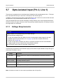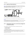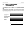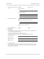
1
Basler ace
USER’S MANUAL FOR USB 3.0 CAMERAS
Document Number: AW001234
Version: 01 Language: 000 (English)
Release Date: 04 June 2013
This Manual Applies to Prototype Cameras Only
For customers in the U.S.A.
This equipment has been tested and found to comply with the limits for a Class A digital device,
pursuant to Part 15 of the FCC Rules. These limits are designed to provide reasonable protection
against harmful interference when the equipment is operated in a commercial environment. This
equipment generates, uses, and can radiate radio frequency energy and, if not installed and used
in accordance with the instruction manual, may cause harmful interference to radio
communications. Operation of this equipment in a residential area is likely to cause harmful
interference in which case the user will be required to correct the interference at his own expense.
You are cautioned that any changes or modifications not expressly approved in this manual could
void your authority to operate this equipment.
The shielded interface cable recommended in this manual must be used with this equipment in
order to comply with the limits for a computing device pursuant to Subpart J of Part 15 of FCC Rules.
For customers in Canada
This apparatus complies with the Class A limits for radio noise emissions set out in Radio
Interference Regulations.
Pour utilisateurs au Canada
Cet appareil est conforme aux normes Classe A pour bruits radioélectriques, spécifiées dans le
Règlement sur le brouillage radioélectrique.
Life Support Applications
These products are not designed for use in life support appliances, devices, or systems where
malfunction of these products can reasonably be expected to result in personal injury. Basler
customers using or selling these products for use in such applications do so at their own risk and
agree to fully indemnify Basler for any damages resulting from such improper use or sale.
Warranty Note
Do not open the housing of the camera. The warranty becomes void, if the housing is opened.
All material in this publication is subject to change without notice and is copyright
Basler AG.
Contacting Basler Support Worldwide
Europe:
Basler AG
An der Strusbek 60 - 62
22926 Ahrensburg
Germany
Tel.: +49-4102-463-515
Fax.: +49-4102-463-599
[email protected]
Americas:
Basler, Inc.
855 Springdale Drive, Suite 203
Exton, PA 19341
U.S.A.
Tel.: +1-610-280-0171
Fax.: +1-610-280-7608
[email protected]
Asia:
Basler Asia Pte. Ltd
8 Boon Lay Way
# 03 - 03 Tradehub 21
Singapore 609964
Tel.: +65-6425-0472
Fax.: +65-6425-0473
[email protected]
www.baslerweb.com
AW00123401000
Table of Contents
Table of Contents
1 Specifications, Requirements, and Precautions . . . . . . . . . . . . . . . . . . . . . . . 1
1.1
Models . . . . . . . . . . . . . . . . . . . . . . . . . . . . . . . . . . . . . . . . . . . . . . . . . . . . . . . . . . . . . . 1
1.2
General Specifications . . . . . . . . . . . . . . . . . . . . . . . . . . . . . . . . . . . . . . . . . . . . . . . . . . 2
1.3
Spectral Response . . . . . . . . . . . . . . . . . . . . . . . . . . . . . . . . . . . . . . . . . . . . . . . . . . . . . 6
1.3.1 Mono Camera Spectral Response . . . . . . . . . . . . . . . . . . . . . . . . . . . . . . . . . . . 6
1.3.2 Color Camera Spectral Response . . . . . . . . . . . . . . . . . . . . . . . . . . . . . . . . . . . 9
1.4
Mechanical Specifications . . . . . . . . . . . . . . . . . . . . . . . . . . . . . . . . . . . . . . . . . . . . . . 12
1.4.1 Camera Dimensions and Mounting Points. . . . . . . . . . . . . . . . . . . . . . . . . . . . 12
1.4.2 Maximum Allowed Lens Thread Length. . . . . . . . . . . . . . . . . . . . . . . . . . . . . . 13
1.5
Software Licensing Information . . . . . . . . . . . . . . . . . . . . . . . . . . . . . . . . . . . . . . . . . . 14
1.6
Avoiding EMI and ESD Problems . . . . . . . . . . . . . . . . . . . . . . . . . . . . . . . . . . . . . . . . . 15
1.7
Environmental Requirements . . . . . . . . . . . . . . . . . . . . . . . . . . . . . . . . . . . . . . . . . . . . 16
1.7.1 Temperature and Humidity. . . . . . . . . . . . . . . . . . . . . . . . . . . . . . . . . . . . . . . . 16
1.7.2 Heat Dissipation . . . . . . . . . . . . . . . . . . . . . . . . . . . . . . . . . . . . . . . . . . . . . . . . 16
1.8
Precautions. . . . . . . . . . . . . . . . . . . . . . . . . . . . . . . . . . . . . . . . . . . . . . . . . . . . . . . . . . 17
2 Installation . . . . . . . . . . . . . . . . . . . . . . . . . . . . . . . . . . . . . . . . . . . . . . . . . . . . . 19
3 Camera Drivers and Tools for Changing Camera Parameters . . . . . . . . . . . 21
3.1
The Basler pylon 4 Camera Software Suite . . . . . . . . . . . . . . . . . . . . . . . . . . . . . . . . .
3.1.1 The pylon Viewer . . . . . . . . . . . . . . . . . . . . . . . . . . . . . . . . . . . . . . . . . . . . . . .
3.1.2 The pylon USB Configurator . . . . . . . . . . . . . . . . . . . . . . . . . . . . . . . . . . . . . .
3.1.3 The pylon SDK . . . . . . . . . . . . . . . . . . . . . . . . . . . . . . . . . . . . . . . . . . . . . . . . .
21
22
22
22
4 Camera Functional Description. . . . . . . . . . . . . . . . . . . . . . . . . . . . . . . . . . . . 23
4.1
Overview (All Models Except acA2500-14) . . . . . . . . . . . . . . . . . . . . . . . . . . . . . . . . . 23
4.2
Overview (acA2500-14 Only) . . . . . . . . . . . . . . . . . . . . . . . . . . . . . . . . . . . . . . . . . . . . 25
5 Physical Interface . . . . . . . . . . . . . . . . . . . . . . . . . . . . . . . . . . . . . . . . . . . . . . . 27
5.1
General Description of the Camera Connections . . . . . . . . . . . . . . . . . . . . . . . . . . . . . 27
5.2
Camera Connector Pin Numbering and Assignments . . . . . . . . . . . . . . . . . . . . . . . . . 28
5.2.1 6-pin Connector Pin Numbering and Assignments . . . . . . . . . . . . . . . . . . . . . 28
5.2.2 USB3.0 Micro-B Port Pin Numbering and Assignments . . . . . . . . . . . . . . . . . 29
5.3
Camera Connector Types. . . . . . . . . . . . . . . . . . . . . . . . . . . . . . . . . . . . . . . . . . . . . . . 29
5.3.1 6-pin Connector . . . . . . . . . . . . . . . . . . . . . . . . . . . . . . . . . . . . . . . . . . . . . . . . 29
5.3.2 USB 3.0 Micro-B Port. . . . . . . . . . . . . . . . . . . . . . . . . . . . . . . . . . . . . . . . . . . . 29
5.4
LED Indicator . . . . . . . . . . . . . . . . . . . . . . . . . . . . . . . . . . . . . . . . . . . . . . . . . . . . . . . . 29
5.5
Camera Cabling Requirements . . . . . . . . . . . . . . . . . . . . . . . . . . . . . . . . . . . . . . . . . . 30
5.5.1 USB 3.0 Cable . . . . . . . . . . . . . . . . . . . . . . . . . . . . . . . . . . . . . . . . . . . . . . . . . 30
5.5.2 I/O Cable . . . . . . . . . . . . . . . . . . . . . . . . . . . . . . . . . . . . . . . . . . . . . . . . . . . . . 30
5.6
Camera Power . . . . . . . . . . . . . . . . . . . . . . . . . . . . . . . . . . . . . . . . . . . . . . . . . . . . . . . 31
Basler ace USB 3.0
i
Table of Contents
AW00123401000
5.7
Opto-isolated Input (Pin 2, Line 1) . . . . . . . . . . . . . . . . . . . . . . . . . . . . . . . . . . . . . . . .
5.7.1 Voltage Requirements . . . . . . . . . . . . . . . . . . . . . . . . . . . . . . . . . . . . . . . . . . .
5.7.2 Electrical Characteristics . . . . . . . . . . . . . . . . . . . . . . . . . . . . . . . . . . . . . . . . .
5.7.3 Selecting the Input Line as the Source Signal for a Camera Function . . . . . .
32
32
33
33
5.8
Opto-isolated Output (Pin 4, Line 2) . . . . . . . . . . . . . . . . . . . . . . . . . . . . . . . . . . . . . . .
5.8.1 Voltage Requirements . . . . . . . . . . . . . . . . . . . . . . . . . . . . . . . . . . . . . . . . . . .
5.8.2 Electrical Characteristics . . . . . . . . . . . . . . . . . . . . . . . . . . . . . . . . . . . . . . . . .
5.8.3 Selecting a Source Signal for the Output Line . . . . . . . . . . . . . . . . . . . . . . . . .
34
34
35
36
5.9
Direct-coupled General Purpose I/O (GPIO; Pin 1, Line 3; Pin 3, Line 4) . . . . . . . . . .
5.9.1 Introduction . . . . . . . . . . . . . . . . . . . . . . . . . . . . . . . . . . . . . . . . . . . . . . . . . . .
5.9.2 Operation as an Input . . . . . . . . . . . . . . . . . . . . . . . . . . . . . . . . . . . . . . . . . . .
5.9.2.1
Voltage Requirements. . . . . . . . . . . . . . . . . . . . . . . . . . . . . . . . . . .
5.9.2.2
Electrical Characteristics . . . . . . . . . . . . . . . . . . . . . . . . . . . . . . . . .
5.9.3 Selecting the Input as the Source Signal for a Camera Function . . . . . . . . . .
5.9.4 Operation as an Output . . . . . . . . . . . . . . . . . . . . . . . . . . . . . . . . . . . . . . . . . .
5.9.4.1
Voltage Requirements. . . . . . . . . . . . . . . . . . . . . . . . . . . . . . . . . . .
5.9.4.2
Electrical Characteristics . . . . . . . . . . . . . . . . . . . . . . . . . . . . . . . . .
5.9.4.3
Selecting a Source Signal for the Output Line . . . . . . . . . . . . . . . .
36
36
37
37
37
39
39
39
40
41
6 Troubleshooting and Support . . . . . . . . . . . . . . . . . . . . . . . . . . . . . . . . . . . . . 43
6.1
Tech Support Resources . . . . . . . . . . . . . . . . . . . . . . . . . . . . . . . . . . . . . . . . . . . . . . . 43
6.2
Obtaining an RMA Number . . . . . . . . . . . . . . . . . . . . . . . . . . . . . . . . . . . . . . . . . . . . . 43
6.3
Before Contacting Basler Technical Support . . . . . . . . . . . . . . . . . . . . . . . . . . . . . . . . 44
Revision History . . . . . . . . . . . . . . . . . . . . . . . . . . . . . . . . . . . . . . . . . . . . . . . . . . . . . . . . . . . 47
Index . . . . . . . . . . . . . . . . . . . . . . . . . . . . . . . . . . . . . . . . . . . . . . . . . . . . . . . . . . . . . . . . . . . . . 49
ii
Basler ace USB 3.0
AW00123401000
Table of Contents
Release Notes
This version of the Basler ace USB 3.0 User’s Manual provides initial information that is particularly
relevant to camera design-in.
A future version of the manual will provide additional information, e.g. about image acquisition
(triggering) and the camera’s features.
Basler ace USB 3.0
iii
Table of Contents
iv
AW00123401000
Basler ace USB 3.0
AW00123401000
Specifications, Requirements, and Precautions
1 Specifications, Requirements,
and Precautions
This chapter lists the camera models covered by the manual. It provides the general specifications
for those models and the basic requirements for using them.
This chapter also includes specific precautions that you should keep in mind when using the
cameras. We strongly recommend that you read and follow the precautions.
1.1
Models
The current Basler ace USB3 Vision camera models are listed in the top row of the specification
tables on the next pages of this manual. The camera models are differentiated by their sensor size,
their maximum frame rate at full resolution, and whether the camera’s sensor is mono or color.
Unless otherwise noted, the material in this manual applies to all of the camera models listed in the
tables. Material that only applies to a particular camera model or to a subset of models, such as to
color cameras only, will be so designated.
Basler ace USB 3.0
1
Specifications, Requirements, and Precautions
1.2
AW00123401000
General Specifications
Specification
acA640-120um/uc
acA1300-30um/uc
Sensor Size
(H x V pixels)
gm: 659 x 494
gm: 1296 x 966
gc: 658 x 492
gc: 1294 x 964
Sensor Type
Sony ICX618 ALA/AQA
Progressive scan CCD
Sony ICX445 AL/AQ
Progressive scan CCD
Global shutter
Global shutter
Optical Size
1/4"
1/3"
Pixel Size (H x V)
5.6 µm x 5.6 µm
3.75 µm x 3.75 µm
Max. Frame Rate
(at full resolution)
120 fps
30 fps
Mono/Color
Mono or color
(color models include a Bayer pattern RGB filter on the sensor)
Data Output Type
USB 3.0, nominal max. 5 Gbit/s (SuperSpeed)
Pixel Data Formats
Mono Models:
Mono 8
Mono 12p
Mono 12
Color Models:
Mono 8
Bayer BG 12p
Bayer BG 8
YCbCr422_8
Bayer BG 12
ADC Bit Depth
12 bits
Synchronization
Via external trigger signal, via the USB 3.0 port or free run
Exposure Control
Via external trigger signal or programmable via the camera API
Camera Power
Requirements
Nominal +5 VDC, compliant with the Universal serial Bus 3.0 specification, supplied
via the camera’s USB 3.0 port
(Unless otherwise noted,
maximum values are
indicated for power
consumption).
~ 2.4 W @ 5 VDC
I/O Lines
1 opto-isolated input line, 1 opto-isolated output line, and 2 direct-coupled GPIO
lines
Lens Adapter
C-mount
Size (L x W x H)
~2.5 W (typical) @ 5 VDC
Note: When using extremely small AOIs,
power consumption can increase to
3.0 W.
29.3 mm x 29 mm x 29 mm (without lens adapter or connectors)
48.2 mm x 29 mm x 29 mm (with lens adapter and connectors)
Weight
< 80 g
Conformity
CE, UL (in preparation), FCC, GenICam v. 2.0, GigE Vision, IP30, RoHS, USB3
Vision, USB-IF (in preparation)
Table 1: General Specifications
2
Basler ace USB 3.0
AW00123401000
Specifications, Requirements, and Precautions
Specification
acA640-120um/uc
acA1300-30um/uc
Software
Basler pylon 4 Camera Software Suite (version 4.0 or higher)
Available for Windows in 32 and 64 bit versions.
Table 1: General Specifications
Basler ace USB 3.0
3
Specifications, Requirements, and Precautions
AW00123401000
Specification
acA1600-20um/uc
acA2500-14um/uc
Sensor Size
(H x V pixels)
gm: 1628 x 1236
gm: 2592 x 1944
gc: 1624 x 1234
gc:
Sensor Type
Sony ICX274 AL/AQ
Progressive scan CCD
Aptina MT9P031
Global shutter
Rolling shutter
Optical Size
1/1.8"
1/2.5"
Pixel Size (H x V)
4.4 µm x 4.4 µm
2.2 µm x 2.2 µm
Max. Frame Rate
(at full resolution)
20 fps
14 fps
Mono/Color
Mono or color (color models include a Bayer pattern RGB filter on the sensor)
Data Output Type
USB 3.0, nominal max. 5 Gbit/s (SuperSpeed)
Pixel Data Formats
Mono Models:
Color Models:
Mono 8
2590 x 1942
Progressive scan CMOS
Mono Models:
Mono 8
Mono 12
Mono 12
Mono 12p
Mono 12p
Mono 8
Color Models:
Mono 8
Bayer BG 8
Bayer GB 8
Bayer BG 12
Bayer BG 12p
Bayer GB 12
Bayer GB 12p
YCbCr422_8
YCbCr422_8
ADC Bit Depth
12 bits
Synchronization
Via external trigger signal, via the USB 3.0 port or free run
Exposure Control
Via external trigger signal or programmable via the camera API
Camera Power
Requirements
Nominal +5 VDC, compliant with the Universal serial Bus 3.0 specification, supplied
via the camera’s USB 3.0 port
(Unless otherwise noted,
maximum values are
indicated for power
consumption).
~ 3.5 W @ 5 VDC
I/O Lines
1 opto-isolated input line, 1 opto-isolated output line, and 2 direct-coupled GPIO
lines
Lens Adapter
C-mount
Size (L x W x H)
42.0 mm x 29 mm x 29 mm (without lens adapter or connectors)
~2.2 W @ 5 VDC
48.2 mm x 29 mm x 29 mm (with lens adapter and connectors)
Weight
< 80 g
Conformity
CE, UL (in preparation), FCC, GenICam v. 2.0, GigE Vision, IP30, RoHS, USB3
Vision, USB-IF (in preparation)
Table 2: General Specifications
4
Basler ace USB 3.0
AW00123401000
Specifications, Requirements, and Precautions
Specification
acA1600-20um/uc
acA2500-14um/uc
Software
Basler pylon 4 Camera Software Suite (version 4.0 or higher)
Available for Windows in 32 and 64 bit versions.
Table 2: General Specifications
Basler ace USB 3.0
5
Specifications, Requirements, and Precautions
1.3
Spectral Response
1.3.1
Mono Camera Spectral Response
AW00123401000
The following graphs show the spectral response for each available monochrome camera model.
Relative Response
The spectral response curves exclude lens characteristics and light source
characteristics.
Wavelength (nm)
Fig. 1: acA640-120um Spectral Response (From Sensor Data Sheet)
6
Basler ace USB 3.0
AW00123401000
Specifications, Requirements, and Precautions
1.0
0.9
Relative Response
0.8
0.7
0.6
0.5
0.4
0.3
0.2
0.1
0.0
400
500
600
700
800
900
1000
Wavelength (nm)
Relative Response
Fig. 2: acA1300-30um Spectral Response (From Sensor Data Sheet)
Wavelength (nm)
Fig. 3: acA1600-20um Spectral Response (From Sensor Data Sheet)
Basler ace USB 3.0
7
Specifications, Requirements, and Precautions
AW00123401000
70
Quantum Efficiency (%)
60
50
40
30
20
10
0
350
450
550
650
750
850
950
1050
1150
Wavelength (nm)
Fig. 4: acA2500-14um Spectral Response (From Sensor Data Sheet)
8
Basler ace USB 3.0
AW00123401000
1.3.2
Specifications, Requirements, and Precautions
Color Camera Spectral Response
The following graphs show the spectral response for each available color camera model.
The spectral response curves exclude lens characteristics, light source
characteristics, and IR-cut filter characteristics.
To obtain best performance from color models of the camera, use of a dielectric
IR cut filter is recommended. The filter should transmit in a range from 400 nm to
700 ... 720 nm, and it should cut off from 700 ... 720 nm to 1100 nm.
Relative Response
A suitable IR cut filter is built into the lens adapter on color models of the camera.
Blue
Green
Red
Wavelength (nm)
Fig. 5: acA640-120uc Spectral Response (From Sensor Data Sheet)
Basler ace USB 3.0
9
Specifications, Requirements, and Precautions
AW00123401000
1.0
0.9
Relative Response
0.8
0.7
0.6
Blue
0.5
Green
Red
0.4
0.3
0.2
0.1
0.0
4 00
450
5 00
550
60 0
650
700
Wavelength (nm)
Relative Response
Fig. 6: acA1300-30uc Spectral Response (From Sensor Data Sheet)
Blue
Green
Red
Wavelength (nm)
Fig. 7: acA1600-20uc Spectral Response (From Sensor Data Sheet)
10
Basler ace USB 3.0
AW00123401000
Specifications, Requirements, and Precautions
50
Blue
45
Green
Quantum Efficiency (%)
40
Red
35
30
25
20
15
10
5
0
35 0
400
450
500
550
600
650
700
750
Wavelength (nm)
Fig. 8: acA2500-14uc Spectral Response (From Sensor Data Sheet)
Basler ace USB 3.0
11
Specifications, Requirements, and Precautions
1.4
AW00123401000
Mechanical Specifications
The camera housing conforms to protection class IP30 assuming that the lens mount is covered by
a lens or by the protective plastic seal that is shipped with the camera.
1.4.1
Camera Dimensions and Mounting Points
The dimensions in millimeters for cameras equipped with a C-mount lens adapter are as shown in
Figure 9.
23.7 (dimension for M3)
15
Bottom
12
20
14.5
8.5
4.5
Camera housings are equipped with mounting holes on the bottom as shown in the drawings.
3 x M3; 3 deep
4 x M2; 3 deep
22 (dimension for M2)
16.5
29
17.526
Photosensitive surface
of the sensor
12
29.3
29
27.87
7.6
22.2
29
29
20.7
14.5
5.5
18
41.3
6.9
2 x M2; 4 deep
Reference Plane
Top
Not to Scale
Fig. 9: Mechanical Dimensions (in mm) for Cameras with the C-mount Lens Adapter
12
Basler ace USB 3.0
AW00123401000
1.4.2
Specifications, Requirements, and Precautions
Maximum Allowed Lens Thread Length
The C-mount lens mount on all cameras is normally equipped with a plastic filter holder. The length
of the threads can be a maximum of 9.6 mm, and the lens can intrude into the camera body a
maximum of 10.8 mm (see Figure 10):
The thread length can be a maximum of 9.6 mm, and the lens can intrude into the camera body a
maximum of 10.8 mm.
NOTICE
If either of these limits is exceeded, the lens mount or the filter holder will be damaged or
destroyed and the camera will no longer operate properly.
Note that on color cameras, the filter holder will be populated with an IR cut filter. On monochrome
cameras, the filter holder will be present, but will not be populated with an IR cut filter.
C-mount Lens
(9.6)
23.1 Max
(11)
C-mount Thread
Filter Holder
IR Cut Filter
(color cameras only)
Unthreaded
Thread: 9.6 Max
10.8 Max
Not to Scale
Fig. 10: Maximum Lens Thread Length (Dimensions in mm) for Cameras with the C-mount Lens Adapter
Basler ace USB 3.0
13
Specifications, Requirements, and Precautions
1.5
AW00123401000
Software Licensing Information
The software in the camera includes the LZ4 implementation. The copyright information for this
implementation is as follows:
LZ4 - Fast LZ compression algorithm
Copyright (C) 2011-2012, Yann Collet.
BSD 2-Clause License: www.opensource.org/licenses/bsd-license.php
Redistribution and use in source and binary forms, with or without modification, are permitted
provided that the following conditions are met:
1. Redistributions of source code must retain the above copyright notice, this list of conditions
and the following disclaimer.
2. Redistributions in binary form must reproduce the above copyright notice, this list of conditions
and the following disclaimer in the documentation and/or other materials provided with the
distribution.
THIS SOFTWARE IS PROVIDED BY THE COPYRIGHT HOLDERS AND CONTRIBUTORS "AS
IS" AND ANY EXPRESS OR IMPLIED WARRANTIES, INCLUDING, BUT NOT LIMITED TO, THE
IMPLIED WARRANTIES OF MERCHANTABILITY AND FITNESS FOR A PARTICULAR
PURPOSE ARE DISCLAIMED. IN NO EVENT SHALL THE COPYRIGHT OWNER OR
CONTRIBUTORS BE LIABLE FOR ANY DIRECT, INDIRECT, INCIDENTAL, SPECIAL,
EXEMPLARY, OR CONSEQUENTIAL DAMAGES (INCLUDING, BUT NOT LIMITED TO,
PROCUREMENT OF SUBSTITUTE GOODS OR SERVICES; LOSS OF USE, DATA, OR
PROFITS; OR BUSINESS INTERRUPTION) HOWEVER CAUSED AND ON ANY THEORY OF
LIABILITY, WHETHER IN CONTRACT, STRICT LIABILITY, OR TORT (INCLUDING
NEGLIGENCE OR OTHERWISE) ARISING IN ANY WAY OUT OF THE USE OF THIS
SOFTWARE, EVEN IF ADVISED OF THE POSSIBILITY OF SUCH DAMAGE.
14
Basler ace USB 3.0
AW00123401000
1.6
Specifications, Requirements, and Precautions
Avoiding EMI and ESD Problems
The cameras are frequently installed in industrial environments. These environments often include
devices that generate electromagnetic interference (EMI) and they are prone to electrostatic
discharge (ESD). Excessive EMI and ESD can cause problems with your camera such as false
triggering or can cause the camera to suddenly stop capturing images. EMI and ESD can also have
a negative impact on the quality of the image data transmitted by the camera.
To avoid problems with EMI and ESD, you should follow these general guidelines:
Always use high quality shielded cables. The use of high quality cables is one of the best
defenses against EMI and ESD.
Try to use camera cables that are the correct length and try to run the camera cables and
power cables parallel to each other. Avoid coiling camera cables. If the cables are too long,
use a meandering path rather then coiling the cables.
Avoid placing camera cables parallel to wires carrying high-current, switching voltages such as
wires supplying stepper motors or electrical devices that employ switching technology. Placing
camera cables near to these types of devices can cause problems with the camera.
Attempt to connect all grounds to a single point, e.g., use a single power outlet for the entire
system and connect all grounds to the single outlet. This will help to avoid large ground loops.
(Large ground loops can be a primary cause of EMI problems.)
Use a line filter on the main power supply.
Install the camera and camera cables as far as possible from devices generating sparks. If
necessary, use additional shielding.
Decrease the risk of electrostatic discharge by taking the following measures:
Use conductive materials at the point of installation (e.g., floor, workplace).
Use suitable clothing (cotton) and shoes.
Control the humidity in your environment. Low humidity can cause ESD problems.
The Basler application note called Avoiding EMI and ESD in Basler Camera
Installations provides much more detail about avoiding EMI and ESD.
This application note can be obtained from the Downloads section of our website:
www.baslerweb.com
Basler ace USB 3.0
15
Specifications, Requirements, and Precautions
AW00123401000
1.7
Environmental Requirements
1.7.1
Temperature and Humidity
Housing temperature during operation:
0 °C ... +50 °C (+32 °F ... +122 °F)
Humidity during operation:
20 % ... 80 %, relative, non-condensing
Storage temperature:
-20 °C ... +80 °C (-4 °F ... +176 °F)
Storage humidity:
20 % ... 80 %, relative, non-condensing
1.7.2
Heat Dissipation
You must provide sufficient heat dissipation to maintain the temperature of the camera housing at
50 °C or less. Since each installation is unique, Basler does not supply a strictly required technique
for proper heat dissipation. Instead, we provide the following general guidelines:
In all cases, you should monitor the temperature of the camera housing and make sure that the
temperature does not exceed 50 °C. Keep in mind that the camera will gradually become
warmer during the first hour of operation. After one hour, the housing temperature should
stabilize and no longer increase.
If your camera is mounted on a substantial metal component in your system, this may provide
sufficient heat dissipation.
The use of a fan to provide air flow over the camera is an extremely efficient method of heat
dissipation. The use of a fan provides the best heat dissipation.
16
Basler ace USB 3.0
AW00123401000
1.8
Specifications, Requirements, and Precautions
Precautions
NOTICE
Avoid dust on the sensor.
The camera is shipped with a plastic cap on the lens mount. To avoid collecting dust on the
camera’s IR cut filter (color cameras) or sensor (mono cameras), make sure that you always put
the cap in place when there is no lens mounted on the camera.
NOTICE
On all cameras, the lens thread length is limited.
All cameras (mono and color) are equipped with a plastic filter holder located in the lens mount.
The location of the filter holder limits the length of the threads on any lens you use with the
camera. If a lens with a very long thread length is used, the filter holder or the lens mount will be
damaged or destroyed and the camera will no longer operate properly.
For more specific information about the lens thread length, see Section 1.4.2 on page 13.
NOTICE
Voltage outside of the specified range can cause damage.
You must supply camera power that complies with the Universal Serial Bus 3.0 specification.
The camera’s nominal operating voltage is +5 VDC, effective on the camera’s connector.
NOTICE
An incorrect plug can damage the 6-pin connector:
The plug on the cable that you attach to the camera’s 6-pin connector must have 6 female
pins. Using a plug designed for a smaller or a larger number of pins can damage the
connector.
NOTICE
Using a wrong pin assignment can severely damage the camera:
Make sure the cable and plug you connect to the 6-pin connector follow the correct pin
assignment.
Basler ace USB 3.0
17
Specifications, Requirements, and Precautions
AW00123401000
Warranty Precautions
To ensure that your warranty remains in force:
Do not remove the camera’s serial number label
If the label is removed and the serial number can’t be read from the camera’s registers, the warranty
is void.
Do not open the camera housing
Do not open the housing. Touching internal components may damage them.
Keep foreign matter outside of the camera
Be careful not to allow liquid, flammable, or metallic material inside of the camera housing. If
operated with any foreign matter inside, the camera may fail or cause a fire.
Avoid Electromagnetic fields
Do not operate the camera in the vicinity of strong electromagnetic fields. Avoid electrostatic
charging.
Transport Properly
Transport the camera in its original packaging only. Do not discard the packaging.
Clean Properly
Avoid cleaning the surface of the camera’s sensor, if possible. If you must clean it, use a soft, lint
free cloth dampened with a small quantity of high quality window cleaner. Because electrostatic
discharge can damage the sensor, you must use a cloth that will not generate static during cleaning
(cotton is a good choice).
To clean the surface of the camera housing, use a soft, dry cloth. To remove severe stains, use a
soft cloth dampened with a small quantity of neutral detergent, then wipe dry.
Do not use solvents or thinners to clean the housing; they can damage the surface finish.
Read the manual
Read the manual carefully before using the camera!
18
Basler ace USB 3.0
AW00123401000
Installation
2 Installation
The information you will need to do a quick, simple installation of the camera and related software
is included in the Quick Installation Guide for ace USB 3.0 Cameras (AW0012350x000). The
document also includes information about USB 3.0 host controller chipsets that were found to work
well with Basler ace USB 3.0 cameras.
The camera is designed to be connected to a USB 3.0 port is installed in your PC.
When connected to a USB 2.0 port, the Basler ace USB 3.0 camera will be
detected but will not operate.
You can download the Quick Installation Guide from our website: www.baslerweb.com
Basler ace USB 3.0
19
Installation
20
AW00123401000
Basler ace USB 3.0
AW00123401000
Camera Drivers and Tools for Changing Camera Parameters
3 Camera Drivers and Tools for
Changing Camera Parameters
This chapter provides an overview of the camera drivers and the options available for changing the
camera’s parameters. The camera requires the Basler pylon 4 Camera Software Suite or higher.
The options available with the Basler pylon 4 Camera Software Suite let you change parameters
and control the camera by using a stand-alone GUI (known as the pylon Viewer) or by accessing
the camera from within your software application using the driver API. In addition, the pylon USB
Configurator allows you to obtain information about the architecture of the device tree to which your
camera is connected and about the devices, including your camera.
Currently, the Basler pylon 4 Camera Software Suite is available in a Beta version. You can obtain
the software from our website by using this link: www.baslerweb.com/pylon4usb
To help you install the software, you can also download the Quick Installation Guide for USB 3.0
Cameras (AW001235xx000) from the website.
3.1
The Basler pylon 4 Camera Software
Suite
The Basler pylon 4 Camera Software Suite is designed to operate all Basler cameras that have an
IEEE 1394a interface, an IEEE 1394b interface, a GigE interface or a USB 3 interface. It will also
operate some newer Basler camera models with a Camera Link interface. The pylon drivers offer
reliable, real-time image data transport into the memory of your PC at a very low CPU load.
Features in the pylon driver package include:
The pylon USB drivers and the pylon USB Configurator
The Basler GigE Vision drivers (filter driver and performance driver)
IEEE 1394a/b drivers
A Camera Link configuration driver for some newer camera models
A pylon camera API for use with a variety of programming languages
A pylon DirectShow driver
A pylon TWAIN driver
The Basler pylon Viewer and the Basler pylon IP Configurator
Source code samples
A programming guide and API reference.
Basler ace USB 3.0
21
Camera Drivers and Tools for Changing Camera Parameters
AW00123401000
The pylon software includes several tools that you can use to change the parameters on your
camera including the pylon Viewer, the USB Configurator, and the pylon SDK. The remaining
sections in this chapter provide an introduction to the tools.
3.1.1
The pylon Viewer
The pylon Viewer is included in the Basler pylon 4 Camera Software Suite. The pylon Viewer is a
standalone application that lets you view and change most of the camera’s parameter settings via
a GUI based interface. The pylon Viewer also lets you acquire images, display them, and save
them. Using the pylon Viewer is a very convenient way to get your camera up and running quickly
when you are doing your initial camera evaluation or doing a camera design-in for a new project.
For more information about using the pylon Viewer, see the Installation and Setup Guide for
Cameras Used with Basler’s pylon API (AW000611xx000).
3.1.2
The pylon USB Configurator
The pylon USB Configurator is included in the Basler pylon 4 Camera Software Suite besides the
Basler pylon IP Configurator and the Basler pylon CL Configurator. The pylon USB Configurator is
a standalone application. It allows you to obtain information about the architecture of the device tree
to which your camera is connected, about the devices, including your camera, and to prepare a
report.
For more information about using the pylon USB Configurator see the Installation and Setup Guide
for Cameras Used with Basler’s pylon API (AW000611xx000).
3.1.3
The pylon SDK
After the pylon Camera Software Suite has been installed on your PC, you can access all of the
camera’s parameters and can control the camera’s full functionality from within your application
software by using the pylon API. The pylon Programmer’s Guide and the pylon API Reference
contain an introduction to the API and include information about all of the methods and objects
included in the API. The programmer’s guide and API reference are included in the Basler pylon 4
Camera Software Suite.
The Basler pylon SDK includes a set of sample programs that illustrate how to use the pylon API to
parameterize and operate the camera. These samples include Microsoft® Visual Studio® solution
and project files demonstrating how to set up the build environment to build applications based on
the API.
22
Basler ace USB 3.0
AW00123401000
Camera Functional Description
4 Camera Functional
Description
This chapter provides an overview of the camera’s functionality from a system perspective. The
overview will aid your understanding when you read the more detailed information included in the
later chapters of the user’s manual.
4.1
Overview (All Models Except acA2500-14)
The camera provides features such as a global shutter and electronic exposure time control.
Exposure start and exposure time can be controlled by parameters transmitted to the camera via
the Basler pylon API and the USB 3.0 interface. There are also parameters available to set the
camera for single frame acquisition or continuous frame acquisition.
Exposure start can also be controlled via an externally generated "frame start trigger" (ExFSTrig)
signal applied to the camera’s input line. The ExFSTrig signal facilitates periodic or non-periodic
frame acquisition start. Modes are available that allow the length of exposure time to be directly
controlled by the ExFSTrig signal or to be set for a pre-programmed period of time.
Accumulated charges are read out of the sensor when exposure ends. At readout, accumulated
charges are transported from the sensor’s light-sensitive elements (pixels) to the vertical shift
registers (see Figure 11 on page 24). The charges from the bottom row of pixels in the array are
then moved into a horizontal shift register. Next, the charges are shifted out of the horizontal
register. As the charges move out of the horizontal shift register, they are converted to voltages
proportional to the size of each charge. Each voltage is then amplified by a Variable Gain Control
(VGC) and digitized by an Analog-to-Digital converter (ADC). After each voltage has been amplified
and digitized, it passes through an FPGA and into an image buffer. All shifting is clocked according
to the camera’s internal data rate. Shifting continues in a row-wise fashion until all image data has
been read out of the sensor.
The pixel data leaves the image buffer and passes back through the FPGA to a controller where it
is assembled into data packets. The packets are then transmitted by bulk transfer via a USB 3
compliant cable to a USB 3 host adapter of the host PC. The controller also handles transmission
and receipt of control data such as changes to the camera’s parameters.
The image buffer between the sensor and the controller allows data to be read out of the sensor at
a rate that is independent of the data transmission rate between the camera and the host PC. This
ensures that the data transmission rate has no influence on image quality.
Basler ace USB 3.0
23
Camera Functional Description
AW00123401000
Progressive Scan CCD Sensor
Vert.
Shift
Reg.
ADC
Pixels
Vert.
Shift
Reg.
Pixels
Vert.
Shift
Reg.
Pixels
Vert.
Shift
Reg.
Pixels
VGC
Horizontal
Shift Register
Fig. 11: CCD Sensor Architecture - Progressive Scan Sensors
I/O
Acquisition Trigger Wait Signal or
Frame Trigger Wait Signal or
Exposure Active Signal or
Timer 1 Signal
Image
Buffer
Image
Data
Sensor
VGC
ADC
Acquisition Start Trigger Signal or
Frame Start Trigger Signal or
Frame Counter Reset Signal or
Trigger InputCounter Reset Signal
Image
Data
FPGA
Controller
Image
and
Control
Data
PC
Image and
Control Data
and
Power
Control: Gain, Black Level
Control: AOI
Fig. 12: Camera Block Diagram
24
Basler ace USB 3.0
AW00123401000
4.2
Camera Functional Description
Overview (acA2500-14 Only)
The camera provides features such as an electronic rolling shutter and electronic exposure time
control.
Exposure start and exposure time can be controlled by parameters transmitted to the camera via
the Basler pylon API and the GigE interface. There are also parameters available to set the camera
for single frame acquisition or continuous frame acquisition.
Exposure start can also be controlled via an externally generated "frame start trigger" (ExFSTrig)
signal applied to the camera’s input line. The ExFSTrig signal facilitates periodic or non-periodic
frame acquisition start.
Because the camera has a rolling shutter, the exposure start signal will only start exposure of the
first row of pixels in the sensor. Exposure of each subsequent row will then automatically begin with
an increasing temporal shift for each row. The exposure time will be equal for each row.
Accumulated charges are read out of each sensor when exposure ends. At readout, accumulated
charges are transported from the row’s light-sensitive elements (pixels) to the analog processing
controls (see Figure 13 on page 26). As the charges move through the analog controls, they are
converted to voltages proportional to the size of each charge. Each voltage is then amplified by a
Variable Gain Control (VGC). Next the voltages are digitized by an Analog-to-Digital converter
(ADC). After the voltages have been amplified and digitized, they are passed through the sensor’s
digital controls for additional signal processing. The digitized pixel data leaves the sensor, passes
through an FPGA, and moves into an image buffer.
The pixel data leaves the image buffer and passes back through the FPGA to a controller where it
is assembled into data packets. The packets are then transmitted by bulk transfer via a USB 3
compliant cable to a USB 3 host adapter of the host PC. The controller also handles transmission
and receipt of control data such as changes to the camera’s parameters.
The image buffer between the sensor and the controller allows data to be read out of the sensor at
a rate that is independent of the data transmission rate between the camera and the host PC. This
ensures that the data transmission rate has no influence on image quality.
Basler ace USB 3.0
25
Camera Functional Description
AW00123401000
CMOS Sensor
Pixel
Array
Analog Processing
Digitized
Pixel Data
Digital Processing
ADC
Fig. 13: CMOS Sensor Architecture
Acquisition Start Trigger Signal or
Frame Start Trigger Signal or
Frame Counter Reset Signal or
Trigger Input Counter Reset Signal
I/O
Acquisition Trigger Wait Signal or
Frame Trigger Wait Signal or
Exposure Active Signal or
Flash Window Signal or
Timer 1 Signal
Image
Buffer
Image
Data
Sensor
Image
Data
Controller
FPGA
Image
and
Control
Data
Image and
Control Data
and
Power
PC
Control:
AOI, Gain,
Black Level
Fig. 14: Camera Block Diagram
26
Basler ace USB 3.0
AW00123401000
Physical Interface
5 Physical Interface
This chapter provides detailed information, such as pinouts and voltage requirements, for the
physical interface on the camera. This information will be especially useful during your initial
design-in process.
5.1
General Description of the
Camera Connections
The camera is interfaced to external circuity via connectors located on the back of the housing:
A 6-pin connector used to provide access to the camera’s I/O lines
A USB 3.0 Micro-B port used to provide a (nominal) 5 Gbit/s SuperSpeed connection to the
camera.
There is also a LED indicator located on the back of the camera.
Figure 15 shows the location of the two connectors and the LED.
6-pin Connector (I/O)
Green LED Indicator
USB 3.0 Micro-B Port
Fig. 15: Camera Connectors
Basler ace USB 3.0
27
Physical Interface
AW00123401000
5.2
Camera Connector Pin Numbering and
Assignments
5.2.1
6-pin Connector Pin Numbering and
Assignments
The 6-pin connector is used to access the physical input and output lines on the camera.
The pin numbering for the 6-pin connector is as shown in Figure 16.
5
4
6
1
3
2
Fig. 16: Pin Numbering for the 6-pin Connector
The pin assignments and designations for the 6-pin connector are shown in Table 3.
.
Pin
Designation
Function
1
Line 3
Direct-coupled General Purpose I/O (GPIO)
2
Line 1
Opto-isolated I/O IN
3
Line 4
Direct-coupled General Purpose I/O (GPIO)
4
Line 2
Opto-isolated I/O OUT
5
-
Ground for opto-isolated I/O
6
-
Ground for direct-coupled GPIO
Table 3: Pin Assignments for the 6-pin Connector and Related Designations
28
Basler ace USB 3.0
AW00123401000
5.2.2
Physical Interface
USB3.0 Micro-B Port Pin Numbering and
Assignments
The USB 3.0 Micro-B port provides a USB 3.0 connection to supply power to the camera and to
transmit video data and control signals.
Pin numbering and pin assignments adhere to the Universal Serial Bus 3.0 standard.
5.3
Camera Connector Types
5.3.1
6-pin Connector
The 6-pin connector on the camera is a Hirose micro receptacle (part number HR10A-7R-6PB) or
the equivalent.
The recommended mating connector is the Hirose micro plug (part number HR10A-7P-6S) or the
equivalent.
Contact your Basler sales representative to order cable assemblies.
5.3.2
USB 3.0 Micro-B Port
The USB 3.0 Micro-B port for the camera’s USB 3.0 connection is a standard Micro-B USB 3.0
connector with screw lock.
The recommended mating connector is any standard Micro-B USB 3.0 plug. Cables terminated with
screw-lock connectors are available from Basler. Contact your Basler sales representative to order
cable assemblies.
5.4
LED Indicator
There is a green LED indicator on the back of the camera housing (see Figure 16). When the LED
is not lit, the camera will not operate. This applies, for example, when the camera is connected to
a USB 2.0 port.
Basler ace USB 3.0
29
Physical Interface
AW00123401000
5.5
Camera Cabling Requirements
5.5.1
USB 3.0 Cable
Use a high-quality USB 3.0 cable. To avoid EMI, the cable must be shielded. Close proximity to
strong high-frequency electromagnetic fields should be avoided.
When selecting a cable with a length of up to 1.0 m, make sure the cable conforms with the
requirements set by USB-IF. For longer cables, we recommend to obtain a suitable cable from
Basler. Contact your Basler sales representative to order cable assemblies.
5.5.2
I/O Cable
A single I/O cable is used to connect to the camera’s I/O lines.
The end of the I/O cable that connects to the camera must be terminated with a Hirose micro plug
(part number HR10A-7P-6S) or the equivalent. The cable must be wired to conform with the pin
assignments shown in the pin assignment table.
The maximum length of the I/O cable is at least 10 m. The cable must be shielded. To ensure that
input signals are correctly received we strongly recommend to use twisted pair wire. This applies
particularly in an environment with elevated risk of EMI.
Close proximity to strong high-frequency electromagnetic fields should be avoided.
The required 6-pin Hirose plug is available from Basler. Basler also offers a cable assembly that is
terminated with a 6-pin Hirose plug on one end and unterminated on the other. Contact your Basler
sales representative to order connectors or cables.
NOTICE
An incorrect plug can damage the 6-pin connector.
The plug on the cable that you attach to the camera’s 6-pin connector must have 6 female pins.
Using a plug designed for a smaller or a larger number of pins can damage the connector.
Note that the direct-coupled GPIOs are distinctly more susceptible to EMI than the
opto-isolated I/Os. Accordingly, use of the GPIOs in an environment with elevated
risk of EMI calls for taking additional measures like, e.g. using shorter cables or
using twisted pair wire. Under harsh EMI conditions the GPIOs can turn out not to
be usable at all.
Note also that direct-coupled GPIO lines have the advantage of working with very
short delays compared to opto-isolated I/O lines.
30
Basler ace USB 3.0
AW00123401000
5.6
Physical Interface
Camera Power
Power must be supplied to the camera via the USB 3.0 cable plugged into the camera’s USB 3.0
Micro-B port.
NOTICE
Voltage outside of the specified range can cause damage.
You must supply camera power that complies with the Universal Serial Bus 3.0 specification.
The camera’s nominal operating voltage is +5 VDC, effective at the camera’s connector.
Power consumption is as shown in the specification tables in Section 1 of this manual.
Basler ace USB 3.0
31
Physical Interface
5.7
AW00123401000
Opto-isolated Input (Pin 2, Line 1)
The camera is equipped with one dedicated opto-isolated input line designated as Line 1. The input
line is accessed via the 6-pin connector on the back of the camera (pin 2).
In addition, the camera has two direct-coupled GPIO lines, Line 3 and Line 4, that can both be used
as input lines. They are described in Section 5.9 on page 36.
The opto-isolated input line has the advantage of being distinctly more robust against EMI than a
GPIO line used as an input. However, when using the opto-isolated input line, the delays involved
are longer than for a GPIO line.
5.7.1
Voltage Requirements
NOTICE
Voltage outside of the specified range can cause damage.
The recommended voltage range
for the opto-isolated input line differs from the recommended voltage range for the optoisolated output line (see Section 5.8.1 on page 34) and direct-coupled GPIO lines
(Section 5.9 on page 36).
for the I/O input lines of Basler ace USB 3.0 cameras can differ from the recommended
voltage ranges for the I/O input lines of other Basler cameras.
You must supply power within the specified voltage range.
The following requirements and information apply to the camera’s opto-isolated I/O input line (pin 2
of the 6-pin connector; Line 1).
Voltage
+30.0 VDC
Significance
Absolute maximum; the camera can be damaged when the absolute maximum is
exceeded.
+0 to +24 VDC
Recommended I/O input voltage range.
+0 to +1.4 VDC
The voltage indicates a logical 0.
> +1.4 to +2.2 VDC
> +2.2 VDC
Region where the transition threshold occurs; the logical state is not defined in this
region.
The voltage indicates a logical 1.
Table 4: Voltage Requirements and Information for the Opto-isolated Input Line
Note: A minimum current of 5 mA must be provided to the I/O input line.
32
Basler ace USB 3.0
AW00123401000
5.7.2
Physical Interface
Electrical Characteristics
Figure 17 shows a schematic for the opto-isolated input line. See the previous section for input
voltages and their significances. The absolute maximum input voltage is +30.0 VDC. The current
draw for the input line is between 5 mA and 15 mA.
As an example, the use of a TTL or CMOS logic gate in the external circuit is shown.
6-pin
Receptacle
Camera
10
1
Current
Limiter
6
3
4
Logic Gate
2
5
Your
Gnd
Fig. 17: Opto-isolated Input Line Schematic with a Typical External Circuit (Simplified)
For more information about input line pin assignments and pin numbering, see Section 5.2 on
page 28.
For more information about how to use an externally generated frame start trigger (ExFSTrig) signal
to control acquisition start, see a following version of the manual.
For more information about configuring the input line, see a following version of the manual.
5.7.3
Selecting the Input Line as the Source Signal for
a Camera Function
You can select Line 1 to act as the source signal for the following camera functions:
the acquisition start trigger
the frame start trigger
the frame counter reset
the trigger input counter reset
Note that when the input line has been selected as the source signal for a camera function, you
must apply an electrical signal to the input line that is appropriately timed for the function.
For more information about selecting Line 1 as the source signal for a camera function, see a
following version of the manual.
Basler ace USB 3.0
33
Physical Interface
5.8
AW00123401000
Opto-isolated Output (Pin 4, Line 2)
The camera is equipped with one dedicated opto-isolated output line designated as Line 2. The
output line is accessed via the 6-pin connector on the back of the camera (pin 4).
In addition, the camera has two direct-coupled GPIO lines, Line 3 and Line 4, that can both be used
as output lines. They are described in Section 5.9 on page 36.
The opto-isolated output line has the advantage of being distinctly more robust against EMI than a
GPIO line used as an output. However, when using the opto-isolated output line, the delays
involved are longer than for a GPIO line.
5.8.1
Voltage Requirements
NOTICE
Voltage outside of the specified range can cause damage.
The recommended voltage range
for the opto-isolated output line differs from the recommended voltage range for the
opto-isolated input line (see Section 5.7.1 on page 32) and .
for the I/O input lines of Basler ace USB 3.0 cameras can differ from the recommended
voltage ranges for the I/O input lines of other Basler cameras.
You must supply power within the specified voltage range.
The following voltage requirements and information apply to the opto-isolated I/O output line (pin 4
of the 6-pin connector; Line 2).
Voltage
+30.0 VDC
+3.3 to +24 VDC
< +3.3 VDC
Significance
Absolute maximum; the camera can be damaged if the absolute maximum is exceeded.
Recommended I/O output supply voltage range.
The I/O output can operate erratically.
Table 5: Voltage Requirements and Information for the Opto-isolated Output Line
Note: The maximum current allowed through the output circuit is 50 mA.
34
Basler ace USB 3.0
AW00123401000
5.8.2
Physical Interface
Electrical Characteristics
Figure 18 shows a schematic for the opto-isolated output line. See the previous section for
recommended voltages and their significances. The absolute maximum voltage is +30.0 VDC.
The maximum current allowed through the output circuit is 50 mA.
Figure 18 shows a typical external circuit you can use to monitor the output line with a voltage signal
.
Your
Gnd
+3.3 to +24
VDC
1
Camera
6
3
Q1
Voltage
Output
Signal
to You
4
2
5
Your
Gnd
Fig. 18: Opto-isolated Output Line Schematic with a Typical Voltage Output Circuit (Simplified)
Figure 19 shows a typical circuit you can use to monitor the output line with an LED or an
pto-coupler. In this example, the voltage for the external circuit is +24 VDC. Current in the circuit
is limited by an external resistor.
Your Gnd
+24
VDC
Camera
1
6
3
Q1
LED
Output
to You
2.2k
4
2
5
Your
Gnd
Fig. 19: Opto-isolated Output Line Schematic with a Typical LED Output Signal at +24 VDC for the External Circuit
(Simplified)
For more information about output line pin assignments and pin numbering, see Section 5.2 on
page 28.
For more information about the Exposure Active signal, see a following version of the manual.
Basler ace USB 3.0
35
Physical Interface
5.8.3
AW00123401000
Selecting a Source Signal for the Output Line
To make the physical output line useful, you must select a source signal for the line. The camera
has several standard output signals available and any one of them can be selected to act as the
source signal for the output line.
For more information about selecting a source signal for the output line, see a following version of
the manual.
5.9
Direct-coupled General Purpose I/O
(GPIO; Pin 1, Line 3; Pin 3, Line 4)
5.9.1
Introduction
The camera has two direct-coupled GPIO lines that are accessed via pins 1 and 3 of the 6-pin
connector on the back of the camera.
The GPIO lines can be set to operate as inputs to the camera or to operate as camera outputs.
The GPIO lines are designated as Line 3 and Line 4 (see also Section 5.2.1 on page 28).
The direct-coupled GPIO lines are compatible with TTL signals.
The next sections describe the differences in the GPIO electrical functionality when the lines are set
to operate as inputs and when they are set to operate as outputs.
NOTICE
Applying incorrect electrical signals to the camera’s GPIO lines can severely damage the camera.
1. Before you connect any external circuitry to a GPIO line, we strongly recommend that you
set a GPIO line to operate as an input or as an output (according to your needs).
2. Once a line is properly set, make sure that you only apply electrical signals to the line that are
appropriate for the line’s current setting.
Direct-coupled GPIO lines have the advantage of working with very short delays
compared to opto-isolated I/O lines.
The direct-coupled GPIO lines are, however, distinctly more susceptible to
electromagnetic interference.
We therefore strongly recommend to only use the direct-coupled GPIO lines when
significant electromagnetic interference will not occur.
36
Basler ace USB 3.0
AW00123401000
5.9.2
Physical Interface
Operation as an Input
This section describes the electrical operation of a GPIO line when the line has been set to operate
as an input.
5.9.2.1
Voltage Requirements
The following requirements apply to a direct-coupled GPIO line when the line is set as an input.
Voltage
+30.0 VDC
Significance
Absolute maximum; the camera can be damaged when the absolute maximum is
exceeded.
+0 to + 5.0 VDC
Recommended input voltage range (the minimum external pull up voltage is 3.3 VDC as
illustrated in Figure 21).
+0 to +0.8 VDC
The voltage indicates a logical 0.
> +0.8 to +2.0 VDC
> +2.0 VDC
Region where the transition threshold occurs; the logical state is not defined in this
region.
The voltage indicates a logical 1.
Table 6: Voltage Requirements for a Direct-coupled GPIO Line Set as an Input
Your application must be able to accept 2 mA (sink current) from the direct-coupled GPIO input line
without exceeding +0.8 VDC, the upper limit of the low state.
5.9.2.2
Electrical Characteristics
Figure 20 shows the applicable electrical circuit when a GPIO line is set to operate as an input. The
figure is drawn to specifically apply to pin 1 (Line 3) as an example. However, with the necessary
modifications, the figure applies equally to pin 3 (Line 4).
The figure shows, as an example, the use of a TTL or CMOS logic gate in the external circuit. A
different example for an external circuit is shown in Figure 21.
See the previous section for input voltages and their significances. The current draw for each input
line is between 5 mA and 15 mA.
Basler ace USB 3.0
37
Physical Interface
AW00123401000
+3.3 VDC
(Typical)
Camera
Input Buffer
FPGA Input
6-pin
Receptacle
Logic Gate
1
6
3
4
2
Your
Gnd
5
Fig. 20: Direct-coupled GPIO Line Schematic with the GPIO Line Set as an Input and with a Typical External Circuit
Using a Logic Gate (Illustration for Pin 1 as an Example; Simplified)
+3.3 VDC
(Typical)
Camera
Input Buffer
FPGA Input
+3.3 V ... +5.0 V
6-pin
Receptacle
1
6
3
4
2
5
Your
Gnd
Fig. 21: Direct-coupled GPIO Line Schematic with the GPIO Line Set as an Input and with a Typical External Circuit
(Illustration for Pin 1 as an Example; Simplified)
For more information about GPIO pin assignments and pin numbering, see Section 5.2.1 on
page 28.
For more information about setting the GPIO line operation, see a following version of the manual.
38
Basler ace USB 3.0
AW00123401000
5.9.3
Physical Interface
Selecting the Input as the Source Signal for a
Camera Function
When a GPIO line is set to operate as an input, you can select the input to act as the source signal
for the following camera functions:
the acquisition start trigger
the frame start trigger
Note that when the input has been selected as the source signal for a camera function, you must
apply an electrical signal to the input that is appropriately timed for the function.
For more information about using the input line as the source signal for a camera function, see a
following version of the manual.
5.9.4
Operation as an Output
This section describes the electrical operation of the GPIO line when the line has been set to
operate as an output.
5.9.4.1
Voltage Requirements
NOTICE
Voltage outside of the specified range can cause damage.
You must supply power within the specified voltage range.
To ensure that the specified voltage levels for signals transmitted out of the
camera will be reached even under less than favorable conditions (eg. for long
cable lengths, harsh EMI environment, etc.), we recommend to generally use an
external pull up resistor or to connect a "high side load".
Basler ace USB 3.0
39
Physical Interface
AW00123401000
The following voltage requirements apply to a direct-coupled GPIO line when it is set as an
output and when it is in the "off" state:
Voltage
+30.0 VDC
+3.3 to +24 VDC
< +3.3 VDC
Significance
Absolute maximum; the camera can be damaged if the absolute maximum is
exceeded.
Recommended direct-coupled GPIO output supply voltage range.
The direct-coupled GPIO output can operate erratically.
Table 7: Voltage Requirements for a Direct-coupled GPIO Line Set as an Output
The following applies to a direct-coupled GPIO line when it s set as an output and when it is in
the "on" state:
Use a pull up resistor to account for the fact that the camera uses an open collector GPIO
output. The residual voltage will typically be approximately 0.4 V at 50 mA and 25 °C housing
temperature.
The actual residual voltage, however, depends on camera operating temperature, load current,
and production spread.
Note: The maximum current allowed through the output circuit is 50 mA.
5.9.4.2
Electrical Characteristics
As shown in Figure 22, shows the applicable electrical circuit when a GPIO line is set to operate as
an output. The figure is drawn to specifically apply to pin 1 (Line 3) as an example but, with the
necessary modifications, it equally applies to pin 3 (Line 4).
40
Basler ace USB 3.0
AW00123401000
Physical Interface
+3.3 VDC
(Typical)
Camera
Pull Up Resistor
+3.3 to +24
VDC
6-pin
Receptacle
Voltage
Output
Signal
to You
1
6
FPGA Output
3
4
2
5
Your
Gnd
Fig. 22: Direct-coupled GPIO Line Schematic with the GPIO Line Set as an Output and with a Typical Voltage
Output Circuit (Illustration for Pin 1 as an Example; Simplified)
For more information about GPIO pin assignments and pin numbering, see Section 5.2.1 on
page 28.
For more information about setting the GPIO line operation, see a following version of the manual.
5.9.4.3
Selecting a Source Signal for the Output Line
When a GPIO line is configured to act as an output line, you must select a source signal for the line
to make the line useful. The camera has several standard output signals available and any one of
them can be selected to act as the source signal for the output line.
For more information about selecting a source signal for the output line, see a following version of
the manual.
Basler ace USB 3.0
41
Physical Interface
42
AW00123401000
Basler ace USB 3.0
AW00123401000
Troubleshooting and Support
6 Troubleshooting and Support
This chapter outlines the resources available to you, if you need help working with your camera.
6.1
Tech Support Resources
If you need advice about your camera or if you need assistance troubleshooting a problem with your
camera, you can contact the Basler technical support team for your area. Basler technical support
contact information is located in the front pages of this manual.
You will also find helpful information such as frequently asked questions, downloads, and
application notes in the Downloads and the Support sections of our website:
www.baslerweb.com
If you do decide to contact Basler technical support, please take a look at the form that appears on
the last two pages of this section before you call. Filling out this form will help make sure that you
have all of the information the Basler technical support team needs to help you with your problem.
6.2
Obtaining an RMA Number
Whenever you want to return material to Basler, you must request a Return Material Authorization
(RMA) number before sending it back. The RMA number must be stated in your delivery
documents when you ship your material to us! Please be aware that, if you return material without
an RMA number, we reserve the right to reject the material.
You can find detailed information about how to obtain an RMA number in the Support section of our
website: www.baslerweb.com
Basler ace USB 3.0
43
Troubleshooting and Support
6.3
AW00123401000
Before Contacting Basler
Technical Support
To help you as quickly and efficiently as possible when you have a problem with a Basler camera,
it is important that you collect several pieces of information before you contact Basler technical
support.
Copy the form that appears on the next two pages, fill it out, and fax the pages to your local dealer
or to your nearest Basler support center. Or, you can send an e-mail listing the requested pieces of
information and with the requested files attached. Basler technical support contact information is
shown in the title section of this manual.
1
The camera’s product ID:
2
The camera’s serial number:
3
Host adapter that you use
with the camera:
4
Describe the problem in as much
detail as possible:
(If you need more space,
use an extra sheet of paper.)
5
If known, what’s the cause
of the problem?
6
When did the problem occur?
After start.
While running.
After a certain action (e.g., a change of parameters):
44
Basler ace USB 3.0
AW00123401000
7
How often did/does the problem
occur?
Troubleshooting and Support
Once.
Every time.
Regularly when:
Occasionally when:
8
How severe is the problem?
Camera can still be used.
Camera can be used after I take this action:
Camera can no longer be used.
9
10
Did your application ever run
without problems?
Yes
No
Parameter set
It is very important for Basler technical support to get a copy of the exact camera parameters that
you were using when the problem occurred.
To make note of the parameters, use the Basler pylon Viewer.
If you cannot access the camera, please try to state the following parameter settings:
Image Size (AOI):
Pixel Format:
Exposure Time:
Frame Rate:
11
Live image/test image
If you are having an image problem, try to generate and save live images that show the problem.
Also generate and save test images. Please save the images in BMP format, zip them, and send
them to Basler technical support.
Basler ace USB 3.0
45
Troubleshooting and Support
46
AW00123401000
Basler ace USB 3.0
AW00123401000
Revision History
Revision History
Doc. ID Number
Date
Changes
AW00123401000
04 Jun 2013
Initial release of the document. Applies to prototypes only.
Basler ace USB 3.0
47
Revision History
48
AW00123401000
Basler ace USB 3.0
AW00123401000
Index
Index
Numerics
S
6-pin connector ........................................28
software licensing ................................... 14
C
T
cable
I/O .....................................................30
USB 3.0 .............................................30
connector
6-pin ..................................................28
pin assignments ................................28
pin numbering ...................................28
type ...................................................29
transition threshold ........................... 32, 37
U
USB3 Micro-B port .................................. 29
I
input line (direct coupled)
voltage requirements ...................37, 40
input line (opto-isolated)
electrical characteristics ..............32, 34
L
LED indicator ...........................................29
licensing
LZ4 ....................................................14
O
output line (direct coupled)
voltage requirements .........................39
output line (opto-isolated)
voltage requirements .........................34
P
pin assignments ......................................28
pin numbering ..........................................28
port
pin assignments ................................29
pin numbering ...................................29
USB3 Micro-B ...................................29
power and I/O cable
voltage requirements ...................37, 40
Basler ace USB 3.0
49
Index
50
AW00123401000
Basler ace USB 3.0