1
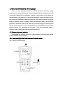
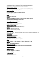
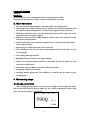
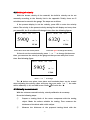
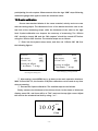
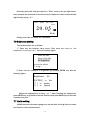
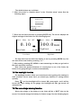
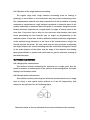
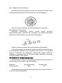
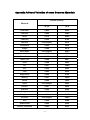
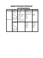
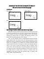
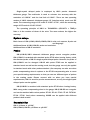
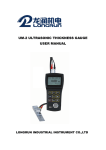
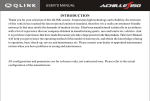
UM-2D ULTRASONIC THICKNESS GAUGE
USER MANUAL
LONGRUN INDUSTRIAL INSTRUMENT CO.,LTD
Content
1. General information of the gauge………………………………..…1
1.1 Measuring mode change………………………………………….…1
1.2 Basic configuration and names of various parts………….…1
1.2.1 Name of various parts……………………………………………1
1.2.2 Standard configuration…………………………………………..2
1.2.3 Optional configuration……………………………………………2
2. Specifications………………………………………………………………..2
3. Main functions……………………………………………………………….4
4. Measuring steps…………………………………………………………….4
4.1 Gauge preparation……………………………………………………4
4.2 The setting of velocity………………………………………….……5
4.3 Velocity measurement………………………………………………5
4.4 Gauge calibration……………………………………………….……6
4.4.1 Fast calibration……………………………………………………6
4.4.2 2-point calibration……………………………………………..…6
4.4.3 Difference between fast calibration and 2-point calibration.…6
4.5 Thickness measurement……………………………………………6
5. Thickness value storing and checking………………………….…7
5.1 Thickness storing……………………………………………………..7
5.2 Thickness checking……………………………………………..……8
6. Erasing the storing thickness values……………………….………8
6.1 Erasing an individual thickness value……………………...……8
6.2 Erasing the present file…………………………………………..…9
6.3 Erasing all data………………………………………………………10
i
6.4 Erasing CAL data……………………………………………………10
7. System setup and function setup……………………………….…10
7.1 System setup…………………………………………………………10
7.2 Function setup…………………………………………………..……11
7.3 Setting the measuring unit, probe and resolution…….……11
7.4 Min capture……………………………………………………………13
7.5 2-point calibration……………………………………………..……14
7.6 Brightness setting…………………………………………...……...15
7.7 Limits setting…………………………………………………………15
7.8 The backlight function………………………………………..……16
7.9 The low voltage warning function……………………….………16
7.10 Ways of turning off……………………………………………..…17
8. Measurement applied skills…………………………………….……17
8.1 The condition requirements on the surface of the
work-piece……………………………………………………………17
8.1.1 Clean surface……………………………………………………17
8.1.2 Enhancing the roughness requirement…………………..……17
8.1.3 Surface of the rough machine processing………….…………18
8.2 Measuring methods………………………………………...……..18
8.2.1 Single-point measurement………………………………..……18
8.2.2 Double-point measurement……………………………….……18
8.2.3 Multiple-point measurement……………………………..……19
8.2.4 Continuous measurement………………………………...……19
8.3 Methods for measuring pipe walls……………………..………19
8.4 Cast Measurement………………………………………….………20
9. Maintenances and cautions…………………………….……………20
ii
9.1 Power source inspection…………………………………….……20
9.2 Cautions………………………………………………………….……21
9.2.1 General cautions…………………………………………..……21
9.2.2 Measuring cautions………………………………………..……21
9.2.3 Changing the probe………………………………………..……21
9.3 Maintenances……………………………………………..…………21
10. After-sale services………………………………………………………22
Appendix A: Sound Velocities of some Common Materials..23
Appendix B: Probe and Measuring Range…………………………24
Appendix C: Various Types of UM series and part of the
specifications…………………………………………….…25
Appendix D: The difference among the five types of
UM series ultrasonic thickness gauge……………26
iii
1. General information of the gauge
There are two operating modes of UM-2D ultrasonic thickness gauge:
standard mode and coating mode. The operating principle of coating mode is E-E
(echo-echo). When there is coating or oil paint on the surface of the object, the
net thickness of the material can be directly measured neither having to remove
the coating nor calibration. While the defect of this mode is that the measuring
range is relatively narrow: 0.118in-0.709in (with standard probe). The operating
principle of standard mode is P-E. With the covered coating, the measurement
will not be very accurate, so the coating should be removed before measuring in
standard mode. The advantage of this mode is that the measuring range is
relatively wide: 0.031in-19.685in (with standard probe).
1.1 Measuring mode change
Press MENU key to make “Std/Coat” into highlighted, and then press ENTER
to alter between the two modes.
1.2 Basic configuration and names of various parts
1.2.1 Name of various parts
-1-
LCD Screen Display:
m/s——unit of sound velocity
BATT——Sign of low voltage
mm or inch——units of thickness 凸——Sign of good-coupling
PT-08——applying probe
Keyboard Function Illustration:
ON——Open
MENU——Menu
CAL——Calibration
VEL——Velocity
MEM——Memory
——Backlight
——Enter
△▽——Turn
1.2.2 Standard configuration
UM series thickness gauge
Standard probe
Carrying case
Two 1.5V alkaline batteries
Couplant
Operating manual
Certification of quality
Packaging list
Insurance card
1.2.3 Optional configuration
Attachable rubber case
Numerous special probes on request (High-temperature probe, cast iron
probe, small probe, mini probe)
Probe cables
Couplants and high-temperature couplant
4-step/6-step block for calibration
Data transmission cable
Application software
2. Specifications
Operating principle:
Standard mode: P-E (pulse-echo) method with dual-element probes
Coating mode: E-E (echo-echo) method with dual-element probes
Probe zero adjustment:
Selectable: 1-point calibration: normal measurement
2-point calibration: curve surface measurement or other special
application with a high precision
V-path correction:
Automatic
Measuring range:
0.8mm to 300mm; 0.031in to 11.81in in standard mode
-2-
3.0mm to 18.0mm; 0.118in to 0.709in in through coating mode
Depending on probe, material and surface condition
Measuring limits of tube:
Φ20mm×3.0mm(PT-08 probe),Φ15mm×2.0mm(PT-06 probe)
The measuring error is up to ±0.1mm
Digital resolution:
H<4in : 0.001in /0.01in or 0.01mm/0.1mm
H≥4in: 0.01in or 0.1mm
Units:
Selectable: inch or mm
Display:
128×64 dot-matrix LCD screen (1.65in×2.24in; 42mm×57mm)
EL backlight and switchable contract ratio
Digit height: 0.54in or 13.75mm
Measurement update rate:
4 Hz in standard measurement mode
25 Hz in MIN capture mode
Material velocity range:
1000 to 9999 m/s; 0.039 to 0.394 inch/µs
Power:
Two 1.5V AA alkaline batteries
Warning with low battery voltage
Operating time:
Up to 200 hours (without backlight) with alkaline batteries, depending on
operating mode
Auto shut-off:
After 5 minutes of non-use
Operating temperature:
-10℃ to +50℃; +14℉ to +122℉
Specification to -20℃/-4℉ on request
Size:
5.86in×2.87in×1.25in; 149mm×73mm×32mm (H×W×D)
Weight:
200g; 7oz (including batteries)
Data logger capacity:
Up to 500 readings can be divided into 5 files (user-selectable)
Operating language:
English and Chinese
Measuring error:
H<1in ±0.002in or ±0.05mm
H≥1in ±0.5%H
Repeatability:
±0.025mm or ±0.001in
-3-
Application software:
UMVIEW
Interfaces:
Serial RS 232C port in combination with a communicative cable;
Data transfer parameters: 8 bits, 1 stop bit, 9600 baud, no parity.
3. Main functions
☆ Two operating modes available: standard mode and coating mode
☆ Data logger: Up to 500 readings can be divided into 5 different material files
for easy store and management. The data cannot get lost after power off.
☆ Thickness restriction alarm: set the thickness limits and the value out of the
limits will cause the alarm ringing.
☆ Minimum value scanning (MIN Capture mode): catch the minimum value
during the measurement.
☆ 2-point calibration: Curve surface measurement or other special application
with a high precision.
☆ Supporting two thickness units of mm and inch.
☆ The calibration value can be stored automatically without loss after turning
off the gauge.
☆ Low voltage warning function.
☆ Backlight: Bring convenience to night working
☆ Delete: The skeptical data in the file or the whole file can be delete, so that
new data can be stored
☆ Automatic shut off: With no operation within 5 minutes
☆ Language: English and Chinese
☆ Coupling status awareness: The stability of coupling can be aware by the
coupling sign.
4. Measuring steps
4.1 Gauge preparation
After plugging-in the probe connector to the gauge and pressing ON, there
will be two beep and the screen lights up. The velocity displayed is that of last
time. The screen display is as follows:
Save1 Menu Std OFF
5900
▲
m/s
PT-08
-4-
4.2 Setting of velocity
With the known velocity of the material, the build-in velocity can be set
manually according to the Velocity List in the appendix. Totally, there are 5
velocities can be stored in the gauge. The steps are as follow:
If the present display is not the velocity, press VEL to enter the velocity
status. The velocity in the present velocity storing file will display and every time
you press VEL, the 5 velocities will change in turn. See the following figures:
Save1
Menu
Std
5900
▲
OFF
Save1
Menu
Std
6320
m/s
▲
PT-08
OFF
m/s
PT-08
Press VEL to enter the velocity status
Press VEL again to change the velocity
If there is not the needed velocity, press △ or ▽ to change. At the same
time, you can store the velocity to the gauge so that you can easily find it next
time. See following figure:
Save1
Menu
Std
5905
▲
OFF
m/s
PT-08
Press △ or ▽ to change
The ▲ below ones place, tens place and hundreds place can be moved
when adjusting the velocity value and every time you press △or ▽, the value
will be added by 1, 10, and 100 in turn. Press
to move the ▲.
4.3 Velocity measurement
With the unknown material velocity, velocity calibration is necessary.
Do as the following steps:
①
Prepare a testing block of the same component with the testing
object. Make its surface suitable for testing. Then measure the
thickness of the block with a slide caliper.
②
Measure the thickness of the prepared testing block with the
-5-
ultrasonic thickness gauge.
③
Press VEL and adjust △ or ▽ until the thickness is the same with
the known thickness of the testing block. The velocity displayed is
that of the testing object.
④
The velocity will be stored into the present velocity unit automatically.
4.4 Gauge calibration
4.4.1 Fast calibration
Calibration should be made every time after changing the probe, which is
very important to ensure the accuracy of the testing. Fast calibration can be
made every time before testing if necessary.
Spread the couplant on the testing block on the gauge, and make the
probe coupled to the testing block until the coupling sign
appears without
flickering. Then press CAL to finish calibration. If the velocity is 5900m/s, the
thickness value display is 4mm. See the following figure:
Save1
Menu
Std
4.00
▲
凸
OFF
㎜
PT-08
Tips: If the velocity is not 5900m/s, the thickness value is not 4.0mm after fast
calibrating and testing the block on the gauge, which is a common phenomenon.
If in coating mode, the gauge could measure directly and without necessarily
calibration.
4.4.2 2-point calibration
In order to make curve surface measurement or other special application
with a high precision, 2-point calibration can be applied. For detail see Chapter
7.5.
4.4.3 Difference between fast calibration and 2-point calibration
① Fast calibration use the testing block on gauge, while the 2-point
calibration can use any block of various materials and thicknesses.
②Fast calibration use only one testing block, while the 2-point calibration
use two blocks with different thicknesses.
4.5 Thickness measurement
After calibration and velocity setting, spread the couplant on the testing area
-6-
of the testing object and coupled the probe with the testing object completely.
The screen will display the thickness value of the testing object. See the
following figure:
Save1
Menu
Std
10.00
▲
凸
OFF
㎜
PT-08
Note: When the probe is coupling to the testing material, there will be a coupling
sign 凸 on the screen; On the contrary, if the coupling status is not very good,
the coupling sign won’t appear, or it will keep flittering. See the following figure:
Save1
Menu
Std
10.00
▲
OFF
㎜
PT-08
5. Thickness value storing and checking
5.1 Thickness storing
Up to 500 thickness values can be divided into 5 files for storing.
Firstly, choose the storing file number. Press MENU key to make “Save” into
highlighted. See the following figure:
Save1
Menu
Std
5900
▲
OFF
m/s
PT-08
Press
to change the file number so that the storing file number can be
fixed. The five files will display in turn. See the following figure:
Save3
Menu
Std
5900
▲
OFF
m/s
PT-08
-7-
Secondly, measure the thickness.
Thirdly, save the reading. After measuring the thickness, the screen will
display the thickness. Then press MEM, there will be a word “Memory” shining
once in the lower left corner, meaning that the storage has finished and the
reading has been stored in the corresponding file.
5.2 Thickness checking
Press MENU to make “Save” into highlighted. Then press
, and the five
files will display in turn so that you can choose the file you want to check. See
the following figure:
Save3
Menu
Std
5900
OFF
m/s
▲
PT-08
Finally, press MEM key to enter the file. See the following figure:
No.001
Total: 005
4.00
㎜
[ENTER] to erase
Note: “No.” is the number of the present data in the file; “Total” is the total
quantity of the data in the present file. You can check the readings in this file by
pressing △ or ▽. Press MENU or continue measuring will help you to the main
operation interface after checking.
6. Erasing the storing thickness values
6.1 Erasing an individual thickness value
In the status of thickness checking, press ENTER key to delete the present
reading.
①Enter into the statue of thickness checking. See the following figure:
-8-
No.001
Total: 005
4.00
㎜
[ENTER] to erase
②Press ENTER key to delete the present reading and the next reading will
appear. See the following figure:
No.001
Total: 004
3.00
㎜
[ENTER] to erase
6.2 Erasing the present file
To delete all the content in the present file, do as the following steps:
① Press MENU key to make “Menu” into highlighted. See the following figure:
Save1
Menu
Std
5900
OFF
m/s
▲
PT-08
Press ENTER key to enter the menu and make “Function setup” into
highlighted by pressing ▽. See the following figure:
System setup
Function setup
Outside alarm
[ENTER] to select
↓to down ↑to up
② Press ENTER key to enter the interface, and select “Erase file” by pressing △
-9-
or ▽. See the following figure:
Erase file
Erase all data
Erase CAL data
to select
↓to down
[ENTER]
③ After selection, press ENTER key and the screen displays as follows:
Press [ENTER]
to confirm
Press [MENU]
to cancel
Then, press ENTER to confirm deleting the present file, and press MENU to
go back to the last interface.
④ After deleting, press VEL or MENU to go back to the main operation interface.
6.3 Erasing all data
To delete all the thickness values in the gauge, just select “Erase all data”
and do other steps as above.
6.4 Erasing CAL data
To delete the calibrating thickness value, just select “Erase CAL data” and do
other steps as above.
7. System setup and function setup
7.1 System setup
Press MENU key to make “Menu” into highlighted. See the following figure:
Save1
Menu
Std
5900
▲
OFF
m/s
PT-08
- 10 -
Then, press ENTER key to enter into the menu. See the following figure:
System setup
Function setup
Outside alarm
[ENTER] to select
↓to down
The “System setup” is highlighted (if not, you can adjust by moving △or▽),
and press ENTER key to enter into system setup menu. Press △or▽ to select the
item you want to alter, and press ENTER to make the alteration.
There are totally four items in system setup, they are: units (metric and
imperial), min capture, 2-point cal and language. You can set these items
according to your need. After setting, you can go back to the main operation
interface by pressing MENU or starting measuring.
7.2 Function setup
Press MENU key to make “Menu” into highlighted. Then, press ENTER key to
enter into the menu. See the following figure:
System setup
Function setup
Outside alarm
[ENTER] to select
↓to down ↑to up
Make “Function setup” into highlighted by moving △or▽, and press ENTER
key to enter into function setup menu. Press △or▽ to select the item you want
to erase or alter, and press ENTER to make it.
There are totally four items in function setup: erase file, erase all data, erase
CAL data and set brightness. You can set these items according to your need.
After setting, you can go back to the main operation interface by pressing MENU
or starting measuring.
7.3 Setting the measuring unit, probe and resolution
- 11 -
UM-2D offers two sorts of measuring units: metric and imperial; two sorts of
resolutions: 0.001in/0.01in or 0.01mm/0.1mm; various sorts of probes: PT-08,
5P-10,PT-12,ZT-12,TG790H,PT-04 and PT-06. You can set the unit according
to your realistic need.
The detailed steps are as follows:
① Enter into the system setup menu, and then move the cursor to “Units”
by moving △or▽. Alter the unit between METRIC and IMPERIAL by pressing
ENTER key. See the following figures:
Units:
Probe:
Resolution:
Units:
Probe:
Resolution:
METRIC
PT-08
HIGH
IMPERIAL
PT-08
HIGH
to select
↓to down
[ENTER]
to select
↓to down
[ENTER]
After altering by pressing ENTER
Choosing the altering item
② Enter into the system setup menu, and then move the cursor to “Probe”
by moving △or▽. Alter the unit among PT-08,5P-10,PT-12,ZT-12,TG790H,
PT-04 and PT-06 by pressing ENTER key. See the following figures:
Units:
METRIC
Units:
Probe:
PT-08
Probe:
5P-10
Probe:
PT-12
Resolution:
HIGH
Resolution:
HIGH
Resolution:
HIGH
to select
↓to down
[ENTER]
Choosing the altering item
METRIC
Units:
METRIC
[ENTER]
to select
↓to down
[ENTER]
to select
↓to down
After altering by pressing ENTER
After altering by pressing ENTER
Note: There are various kinds of probes available in UM-2D. To make precise
measuring, alter the probe type when choosing different probes.
③ Enter into the system setup menu, and then move the cursor to
“Resolution” by moving △or▽. Alter the unit between HIGH (0.001in/0.01mm)
and LOW (0.01in/0.1mm) by pressing ENTER key. See the following figures:
- 12 -
Units:
METRIC
Units:
METRIC
Probe:
PT-08
Probe:
PT-08
Resolution:
HIGH
Resolution:
LOW
to select
↓to down
to select
↓to down
[ENTER]
[ENTER]
Choosing the altering item
After altering by pressing ENTER
7.4 Min capture
Min capture means catching the minimum thickness value among the
measuring results when measuring. The detailed setting steps are as follows:
a) Enter into the system setup menu, and then set “Min capture” ON. (OFF
means to close Min capture while ON means to open the function) See
the following figures:
Probe:
PT-08
Probe:
PT-08
Resolution:
HIGH
Resolution:
HIGH
Min capture
OFF
Min capture
to select
↓to down ↑to up
ON
to select
↓to down ↑to up
[ENTER]
[ENTER]
After altering by pressing ENTER
Choosing the altering item
b) After setting, press MENU key to go back to the main operation interface.
See the following figure:
Save1 Menu Std OFF
10.00
▲
MIN
㎜
PT-08
Note: with “Min capture” on, when the probe is coupling to the work-piece,
the screen displays the present thickness value; when lifting the probe up, the
screen displays the minimum thickness value among the measuring results, and
the min capture sign “MIN” flickers for six times. If you continue to measure
during the time the sign “MIN” flickering, the present thickness value goes on
- 13 -
participating the min capture. Measurement after the sign “MIN” stops flickering
makes the gauge start again to catch the minimum value.
7.5 2-point calibration
Choose two standard blocks of the same material, velocity and curve rate
with the testing object. The thickness of one of the blocks should be near to the
low limit of the measuring scope, while the thickness of the other to the high
limit. 2-point calibration can improve the accuracy of measuring. The “2-Point
CAL” should be turned ON and the “Min capture” should be turned OFF before
using the “2-Point CAL” function. The detailed steps are as follows:
① Enter into the system setup menu, and then set “2-Point CAL” ON. See
the following figures:
Resolution:
HIGH
Resolution:
Min capture
2-Point CAL:
OFF
OFF
Min capture
2-Point CAL:
to select
↓to down ↑to up
HIGH
OFF
ON
to select
↓to down ↑to up
[ENTER]
[ENTER]
After altering by pressing ENTER
Choosing the altering item
② After setting, press MENU key to go back to the main operation interface.
With “2-Point CAL” on, the function of 2-point calibration can be used at any time
when measuring.
③ Process the 2-point calibration. The detailed steps are as follows:
Firstly, measure the thickness of the thinner block. In the status of thickness
display, press CAL, and there will be a “Thin” mark on the top right corner. Adjust
the value to the standard low limit by using △or▽.
Save1 Menu Std OFF
Thin
10.05
▲
㎜
PT-08
- 14 -
Secondly, press CAL, and there will be a “Thick” mark on the top right corner,
then measure the thickness of the thicker block. Adjust the value to the standard
high limit by using △or▽.
Save1 Menu Std OFF
Thick
20.05
▲
㎜
PT-08
Finally, press CAL and finish the calibration.
7.6 Brightness setting
The detailed steps are as follows:
① Enter into the function setup menu. Then move the cursor to “Set
brightness” by moving △or▽. See the following figure:
Erase all data
Erase CAL data
Set brightness
to select
↑to up
[ENTER]
② Enter into the interface of brightness by pressing ENTER key. See the
following figure:
Brightness :
04
[ENTER] to Esc
[↑] to darken
[↓] to lighten
Adjust the brightness by moving △or▽. After finishing the adjustment,
press ENTER key to go back to the last interface and press MENU key to the main
operation interface.
7.7 Limits setting
UM-2D ultrasonic thickness gauge can set low limit and high limit to realize
the function of fast measurement.
- 15 -
The detailed steps are as follows:
① Move the cursor to “Outside alarm” in the “Function setup” menu. See the
following figure:
System setup
Function setup
Outside alarm
[ENTER] to select
↑to up
② Enter into the limit interface by pressing ENTER key. The screen displays the
original settings of the limits. See the following figures:
Save1 Menu Std OFF
0.10
Low limit PT-08
㎜
PT-08
Save1 Menu Std OFF
300.0mm
High limit
PT-08
High limit
Low limit
The high limit and low limit can display in turn by pressing ENTER key. You
can also set the new limits by pressing △or▽.
③ After setting, pressing VEL, MENU or start measuring can help you go back to
the main operation interface.
Note: when the present thickness of a work-piece is out of the limits, the
buzzer in the gauge will give an alarm automatically.
7.8 The backlight function
The backlight function offers you convenience when getting the readings in
dark condition. At the same time, you should pay attention to saving electric
quantity.
Press
and the backlight will be turned ON; press again, and it will be
turned OFF. After taking off the gauge, the backlight will also get turned off
automatically.
7.9 The low voltage warning function
When the voltage of the battery is low, there will be a “BATT” sign on the
screen. You should change the battery for further usage. See the following figure:
- 16 -
Save1
Menu
Std
5900
OFF
▲
m/s
BATT
PT-08
7.10 Ways of turning off
There are two ways of taking off the gauge for you to choose: auto off and
manual off. The gauge will take off in 5 minutes with no operation. You can also
press MENU key to move the cursor to “OFF” and press ENTER key to take off the
gauge.
8. Measurement applied skills
8.1 The condition requirements on the surface of the work-piece
8.1.1 Clean surface
In any ultrasonic measurement scenario, the shape and roughness of the
test surface are of paramount importance. Rough, uneven surface may limit the
penetration of the ultrasound through the material, and result in unstable, and
therefore unreliable, measurement. The surface being measured should be
clean and free of any small particular matter, rust or scale. The presence of such
obstructions will prevent the probe from seating properly against the surface. So
before measuring, all the dust, dirt and rust corrosion should be removed, as well
as the covered paint. Often, a wire brush or scraper will be helpful in cleaning
surfaces.
8.1.2 Enhancing the roughness requirement
The extremely rough surface, such as the pebble-like finish of some cast
irons, will always arouse measuring error or reading lost, which prove most
difficult to measure. Making the surface smooth before measuring is therefore
very important. Often, a wire brush or scraper will be helpful in cleaning surfaces.
Polishing, filing and grinding with rotary sanders or grinding wheels may be used,
though care must be taken to prevent surface gouging, which will inhibit proper
probe coupling. High-viscosity couplant is also usually applied.
- 17 -
8.1.3 Surface of the rough machine processing
The regular slugs after rough machine processing (such as lathing or
planning) on the surface of the work-piece may also arouse measuring errors.
The compensation methods have been mentioned in 8.1.2. In addition to posing
obstacles to measurement, rough surfaces contribute to excessive wear of the
probes, particularly in situations where the probe is “scrubbed” along the surface.
Probes should be inspected on a regular basis, for signs of uneven wear of the
wear face. If the wear face is worn on one side more than another, the sound
beam penetrating the test material may no longer be perpendicular to the
material surface. In this case, it will be difficult to exactly locate tiny irregularities
in the material being measured, as the focus of the sound beam no longer lies
directly beneath the probe. The test result may be more accurate by adjusting
the angle between the sound insulating wall (the metal film through the center
of the probe bottom) of the probe and the slugs of the material and making
them perpendicular or parallel with each other to get the minimum reading as
the thickness value.
8.2 Measuring methods
8.2.1 Single-point measurement
This method involves measuring the thickness at a single point. Use the
probe to measure a random point on the surface of the testing object, the value
display is the thickness value.
8.2.2 Double-point measurement
This method involves performing two thickness measurements near a single
spot by using a dual crystal probe inclined at 0°and 90°respectively, with
respect to the split face. See the following figure:
Take the smaller of the two indicated values as the thickness of the material.
- 18 -
8.2.3 Multiple-point measurement
This method involves performing a number of measurements within a circle
having a maximum diameter of about 30mm. See the following figure:
Take the minimum indicated value as the thickness of the material
8.2.4 Continuous measurement
Continuous
measurement
method
involves
taking
continuous
measurements along a specified line according to the single measurement
method, at intervals of 5mm or less. See the following figure:
Take the minimum indicated value as the thickness of the material
Of the above methods, the particular method used will be determined either
by the prescribed standards or by consultation with the user. If no particular
method is indicated, the double-point measurement method should be
employed in combination with one of other methods. Taking into account the
corrosion condition of the material
8.3 Methods for measuring pipe walls
The thickness of a pipe can be measured accurately with this gauge. The
measurement range is shown in the following table:
Probe type
Pt-08,10 and 12
Pipe diameter(mm)
≥φ20
Thickness(mm)
≥ 1.2
The split-plane of the probe may be along the pipe axis or perpendicular to it
as shown in the following figures:
- 19 -
Pipe samples
In this case, the readings on the screen will change with some regular
patterns and the smallest display value should be taken as the thickness value.
For small pipes, measurement should be made in both directions (moving
probe a little bit). For large pipes, measure the thickness of the wall along the
direction perpendicular to the pipe axis. See the following figure:
Bottom view of probe
8.4 Cast Measurement
There are special features of cast measurement. The grain size of cast
material is relatively rough, and the organization is not very tight. Added with the
rough surface measuring status, the measurement of cast material is very
difficult. So the following tips should be taken:
① Use low frequency probe like ZT-12 in our company.
② When measuring the cast work-piece with no processing on the surface,
high viscosity couplant such as machine oil, grease and water glass are
needed.
③ Calibrate the sound velocity with the standard block, which shares the
same material and same measuring direction with the testing object.
④ Programming 2-point calibration if needed.
9. Maintenances and cautions
9.1 Power source inspection
When the power source voltage is low, there appears a low voltage sign.
Battery should be change promptly in order not to influence the accuracy of the
gauge. Backlight should not be always on, so that the battery can be used for
longer.
Change the battery as the following steps:
① Turn off the gauge.
- 20 -
② Open the battery cassette.
③ Take out the battery, and put in new battery. Pay attention to the polarity.
For long time sparing the gauge, take out the battery in case that they will
leak out the battery electrolyte, which will corrode the battery case and pole
piece.
9.2 Cautions
9.2.1 General cautions
z Avoid shocking and putting the caustic liquid (such as dilute and ethyl
alcohol) into the instrument and the probe. Wipe the cover and window with
little amount of water.
z After using, the coupling paste and the dirt should be wiped away to keep
the instrument clean and free from rust.
z Avoid dripping sweat on the gauge in high temperature. Spread some
grease on the testing block on the gauge if the gauge will not be used for
long and wipe it out when using.
z Prevent the instrument from getting wet and do not leave it in a humid
atmosphere for a long time.
z When the probe is being plugged into or unplugged from the socket, just
hold the metal lead of the plug and push/pull it straight along the axis.
z Do not rotate the plugs, or the probe cable may get damaged.
z Take the batteries out of the chamber if the gauge will not be used for a
long time.
z Don’t try to open the instrument, or the warranty will be void.
9.2.2 Measuring cautions
① Please allow the instruction. With any unusual circumstance and problems,
please call us without hesitation.
② Only when the coupling sign appears and keeps stable, you can get the
reliable results.
③ With the probe worn, the measurement readings will be unstable. Please
change in that case.
9.2.3 Changing the probe
When the sound insulation wall worn out and the following situations appear,
please change the probe:
① When measuring different thicknesses, the readings are all the same.
② There are the sign of coupling and readings only with the probe plugged into
the socket and without measuring.
9.3 Maintenances
Contact with the maintaining department of our company with the following
- 21 -
problems:
① Components damage and the gauge can not be used.
② The display of the screen is disordered.
③ The measuring error is abnormally big with ordinary usage.
4 Keyboard operation is disordered or doesn’t work.
○
As the ultrasonic thickness gauge is a sort of high-tech product, the fixing
work should be made by professional operator. Do not try to open the instrument
by yourself, or we will not be responsible for any of the problem nor the
maintenance service.
10. After-sale services
The ultrasonic thickness gauge products of our company have been tested
strictly with high standards. Customers can enjoy the following services:
① The warranty period is ONE year after buying and the gauge would be
maintained at any time for good.(The wear of the probe is not in the range of
fixing insurance)
② During the warranty period, the breakdowns caused by the quality problems
of the gauge itself can be fixed by our company for free with your guarantee
card.
③ Our company offers you fixing service after the warranty period with a
reasonable costing fee.
- 22 -
Appendix A: Sound Velocities of some Common Materials
Sound Velocity
Material
in/µs
m/s
Aluminum
0.250
6350
Bismuth
0.086
2184
Brass
0.173
4394
Cadmium
0.109
2769
Cast Iron
0.180(apprx)
4572
Constantan
0.206
5232
Copper
0.184
4674
Epoxy Resin
0.100(apprx)
2540
German Silver
0.187
4750
Glass, Crown
0.223
5664
Glass, Flint
0.168
4267
Gold
0.128
3251
Ice
0.157
3988
Iron
0.232
5893
Lead
0.085
2519
Magnesium
0.228
5791
Mercury
0.057
1448
Nickel
0.222
5639
Nylon
0.102(apprx)
2591
Paraffin
0.087
2210
Platinum
0.156
3962
Plexiglass
0.106
2692
Polystyrene
0.092
2337
Porcelain
0.230(apprx)
5842
PVC
0.094
2388
Quartz Glass
0.222
5639
Rubber, vulcanized
0.091
2311
- 23 -
Silver
0.142
3607
Steel, common
0.233
5918
Steel, stainless
0.223
5664
Stellite
0.275(apprx)
6985
Teflon
0.056
1422
Tin
0.131
3327
Titanium
0.240
6096
Tungsten
0.210
5334
Zinc
0.166
4216
Water
0.058
1473
Tips: the table above is for reference, the actual velocities should be measured
with the method mentioned in 4.3 Velocity measurement.
Appendix B: Probe and Measuring Range
Probe
description
Cast iron probe
ZT12
Standard
probe PT12
Standard
probe PT08
Small probe
PT06
Tiny probe
PT04
Frequency
(MHZ)
2
Diameter of the
contact
proportion
0.638in
5
0.472in
5
0.394in
7.5
0.299in
10
0.197in
5
0.551in
Measuring
range(in
steel)
(0.157~
11.811)in
(0.039~
7.874)in
(0.031~
3.937)in
(0.031~
1.181)in
(0.031~
0.787)in
Available
contact
temperature
(50~140)℉
(50~140)℉
(50~140)℉
(50~140)℉
(50~140)℉
High
temperature
probe
(0.157~
3.150)in
- 24 -
Below 572℉
Appendix C: Various Types of UM series and
part of the specifications
Type
UM-3
UM-2/UM-2D
UM-1/UM-1D
Digital
H<0.4in :
resolution
0.0001in/
Unit:
0.001in/ 0.01in
0.01mm/0.1mm 0.001in
0.001mm/0.01
H≥4in:
mm/0.1mm
0.01in
H≥0.4in:
0.1mm
inch/mm
H:
the
height
of
the testing
Specifications object
H<4in :
0.001in /0.01in
0.1mm
0.001in/ 0.01in
0.01mm/0.1mm
Measuring
H<1in
H<1in
error
±0.002in
±0.002in
Unit:
±0.05mm
±0.1mm
inch/mm
H:
the
height
of
the testing
object
H≥1in
H≥1in
±0.5%H
±1%H
- 25 -
Appendix D: The difference among the five types of
UM series ultrasonic thickness gauge
Interfaces:
UM-1/UM-2
Save1
UM-1D/UM-2D
Menu
Limit
5900
▲
OFF
Save1 Menu
Std/Coat OFF
5900
m/s
▲
m/s
PT-08
UM-3
Save1 Menu
I-E/E-E OFF
5900
▲
m/s
HIGH
Operating principles, modes and measuring ranges:
UM-1/UM-2 ultrasonic thickness gauge measures the thickness of an object
by precisely calculating the time of the probe sending ultrasonic pulse with the
help of couplant to the object and passing through the object until the probe
receiving the reflection from the boundary. The operating principle is P-E
(pause-echo). The measuring range is 0.031’’-11.811’’.
There are two operating modes of UM-1D/UM-2D ultrasonic thickness
gauge: standard mode and coating mode. The operating principle of coating
mode is E-E (echo-echo). When there is coating or oil paint on the surface of the
object, the net thickness of the material can be directly measured neither
without necessarily removal of the coating nor without the calibration. While the
defect of this mode is that the measuring range is relatively narrow:
0.118’’-0.709’’ (with standard probe). The operating principle of standard mode
is P-E. With the covered coating, the measurement will not be very accurate, so
the coating should be removed before measuring in standard mode. The
advantage of this mode is that the measuring range is relatively wide:
0.031’’-19.685’’ (with standard probe).
26
Single-crystal delayed probe is employed by UM-3 precise ultrasonic
thickness gauge. The multi-echo is used to enhance the accuracy with the
resolution of 0.0001’’ and the low limit of 0.012’’. There are two operating
modes of UM-3 ultrasonic thickness gauge: I-E (interface-echo) mode and E-E
mode. The measuring range of I-E mode is 0.059’’-0.709’’, while the measuring
range of E-E mode is 0.012’’-0.394’’.
The operating principle of UM-3 is: THICKNESS= (VELOCITY × TIME)/n
Note: n is the number of times of the echo. The more echoes, the higher the
accuracy.
System setup:
Basic items of UM-1/UM-2/UM-1D/UM-2D/UM-3: units, min capture, 2-point cal
and language.
Additional items of UM-2/UM-2D: probe and resolution.
Additional item of UM-3: resolution.
Probe:
UM-1/UM-1D/UM-3 ultrasonic thickness gauge cannot recognize probes.
UM-1/UM-1D is matched with standard probe PT-08 when leaving factory, while
the standard probe of UM-3 is single-crystal delayed probe. However, the probe of
UM-1/UM-1D can be changed. UM-1D with probe PT-08 can be applied in
standard mode as well as the coating mode, but the gauge can only be applied
in standard mode with other probes attached. (Our company can also use other
probe compensating wires in replace to the PT-08 compensating wire to meet
your special testing requirements, so that you can use different types of probes
in the coating mode. Please connect with us when you have special
requirements.) UM-3 is used for precise measurement, so only the single-crystal
delayed probe can be applied.
UM-2/UM-2D is matched with standard probe PT-08 when leaving factory.
With many probe compensating wires in the gauge, UM-2/UM-2D can recognize
and can be matched with various probes(PT-08,5P-10,PT-12,ZT-12,TG790H,
PT-04,PT-06)freely when measuring. UM-2D can be applied with different
probes in both modes.
Repeatability:
UM-1: ±0.1mm or ±0.004’’
UM-2/UM-1D/UM-2D: ±0.05mm or ±0.002’’
27