1
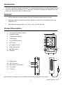
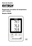
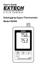
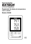
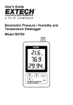
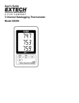
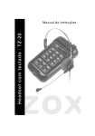
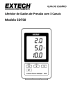
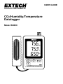
USER GUIDE CO2/Humidity/Temperature Datalogger Model SD800 Introduction Congratulations on your purchase of the Extech SD800 CO2/Temperature/Humidity Datalogger. This meter measures, displays, and stores CO2, temperature and relative humidity readings. Data is stored on a SD card for transfer to a PC. This meter is shipped fully tested and calibrated and, with proper use, will provide years of reliable service Features LCD simultaneously displays Carbon Dioxide, Temperature and Relative Humidity Datalogger date/time stamps and stores readings on an SD card in Excel® format for easy transfer to a PC Selectable data sampling rate: 5, 10, 30, 60, 120, 300, 600 seconds Product Description 1. Humidity/Temperature Sensor 2. Humidity Display 3. Temperature Display 4. CO2 Display 5. LOG (ENTER) button 6. SET button 7. AC adaptor socket 8. CO2 probe socket 9. ▲(TIME) button 1 2 3 4 10 5 6 10. ▼ button 9 7 8 14 11. Reset button 12. RS-232 output 13. SD memory card socket 14. CO2 probe 11 12 15 13 15. CO2 plug Note: Battery Compartment and Tilt Stand are located on the back of the meter. 2 SD800-EU-EN V2.6 07/13 Operation Setup 1. Connect the CO2 probe to the datalogger by inserting the plug into the connector on the bottom of the datalogger. 2. Connect the AC adaptor to the datalogger by inserting the plug into the connector on the bottom of the datalogger. 3. Insert the 6 AAA batteries into the battery compartment. Without these batteries installed, the real time clock will reset every time the ac adaptor is disconnected. Datalogging 1. Open the left side door and insert a formatted SD card Note: The SD card should be at least 1GB in capacity (4GB to 16GB recommended) Note: Do not use memory cards formatted by other meters or cameras. Use the SD card formatting procedure under the advanced features section of this manual to correctly format the card. Note: The internal clock must be set to the correct time See the advanced features section of this manual to set the clock. Note: The default data structure uses a decimal point “.” as the numeric decimal indicator. See the advanced features section of this manual to change this to a comma “,”. Note: If the SD memory card is not installed, “EMPTY” will appear in the display Note: Displayed error messages: CHCArd The memory card is full or there is a problem with the card LobAt The battery is low. No CArd The SD card is not inserted 2. Press the LOGGER button for >2 seconds to begin logging. “DATALOGGER” will appear in the display and the meter will beep each time the data is recorded (if the beeper is enabled). 3. To stop datalogging, press the LOGGER button for >2 seconds. “DATALOGGER” will change to “DATA” and the meter will count down through the recorded data. NOTE: To avoid corrupting data, do not remove the memory card without properly ending the record function. Time/Date/Sample Rate Check Press and Hold the TIME button for >2 seconds and the display will cycle through the date, time and sample rate information. 3 SD800-EU-EN V2.6 07/13 SD Card Data Structure 1. When the SD card if first inserted into the datalogger the folder CHA01 is created. 2. The first datalogging session will then create a file CHA01001.XLS. All data will be saved to this file until the number of columns reaches 30,000. 3. After 30, 000 columns a new file, CHA01002.XLS is created. This is repeated every 30,000 columns until CHA01099.XLS. At this point a new folder, CHA02 is created and the process is repeated. CHA10 is the final folder. Transferring Data to a PC 1. Remove the memory card from the datalogger and plug it into the SD card slot on the PC. 2. Launch Excel® and open the data file on the memory card from within the spreadsheet program. The file will appear similar to the figure below. 4 SD800-EU-EN V2.6 07/13 Advanced Settings The SET function is used to accomplish the following: Format the SD memory card Set the date and time Set the sampling time Set the beeper sound ON/OFF Set the SD card Decimal character Select the Temperature units Set the RS232 data output ON/OFF Set CO2 height compensation in meters Set CO2 height compensation in feet 1. Press and Hold the SET button for >2 seconds to enter the setting mode. The first function (Sd F) will appear in the display. Press the SET button to step through the seven functions. Use the ▲ and ▼ buttons to adjust the selected function. Use the “LOGGER” button to step through fields within a function. In the SET mode, if no button is pressed within 5 seconds the logger will revert to the standard mode. 2. Sd F – Format the SD card. Press the ▲ button to select yES or no. For yES, press the Enter button. When yES and Ent appear, press the Enter key again to format the card and erase all existing data. The screen will display a flashing yEs and ESC while the memory is being erased and formatted. 3. dAtE – Set the date and time. Press the ▲ or ▼ buttons to adjust the selected field. Press the Enter button to store the value and to step through the various fields. 4. SP-t – Set the sample rate. Press the ▲ button to select the desired sample rate and press Enter to store the selection. The selections are: 5, 10, 30, 60, 120, 300, 600 seconds and AUTO. In AUTO, the data will be stored every time there is a temperature change of >1 degree, > 1 %RH or > 50 ppm. 5. bEEP - Set the beeper ON or OFF. Press the ▲ button to select ON or OFF and press Enter to store the selection. 6. dEC - Set the SD card Decimal character. Press the ▲ button to select USA (decimal) or Euro (comma) and press Enter to store the selection. 7. t-CF - Set the Temp. unit to °F or °C and press ENTER to store the selection. 8. rS232 - Set the RS232 data output ON/OFF. Press the ▲ button to select ON or off and press Enter to store the selection 9. HIgh- – Set the height compensation for CO2 in meters. Press the ▲ or ▼ buttons to adjust the selected field to the height (altitude) of the measurement site. This adjustment will improve measurement accuracy. 10. HIghF - Set the height compensation for CO2 in feet. Press the ▲ or ▼ buttons to adjust the selected field to the height (altitude) of the measurement site. This adjustment will improve measurement accuracy. 11. ESC – Exit the setting mode. Press the SET button to return to normal operation. System RESET If a condition appears where the CPU does not respond to keystrokes or the meter seems frozen, press the RESET button on the side of the datalogger (use a paper clip or similar pointed object) to return the meter to a working state. 5 SD800-EU-EN V2.6 07/13 RS232 Interface A serial output is provided to link the meter to a PC’s serial port. Call Technical Assistance for more information on this interface. Battery Warning, Installation and Replacement 1. low battery icon appears in the display, When the AC adaptor is not connected and the the batteries are weak and should be replaced. To replace or install batteries, remove the Philips head screw that secures the rear battery cover and lift off the cover. 2. Replace the six AAA batteries (use alkaline heavy duty type), observing polarity 3. Replace and secure the cover. EU users are legally bound by the Battery Ordinance to return used batteries to community collection points or wherever batteries / accumulators are sold. Disposal in household trash or refuse is prohibited. Disposal: Follow the valid legal stipulations with respect to the disposal of the device at the end of its lifecycle Battery Safety Reminders Please dispose of batteries responsibly; always observe local, state, and federal regulations with regard to battery disposal. Never dispose of batteries in a fire. Batteries may explode or leak. Never mix battery types. Always install new batteries of the 6 SD800-EU-EN V2.6 07/13 Specifications Display Measurement sensors 60 x 50 mm (2.4 x 2.0”) LCD Temperature: Internal sensor Relative Humidity: Precision capacitance type CO2: NDIR <2 min to 63% of final reading typical SD memory card, 1 GB to 16 GB. 5/10/30/60/120/300/600 seconds or Auto. Automatic Approx. 1 second RS 232 0 to 50°C (32 to 122°F) Less than 90% RH 9V AC adaptor. Six (6) AAA (UM4) 1.5 V batteries for clock backup Meter: 240 g (0.53lbs.). Probe 158g (0.35lb) Meter: 132 x 80 x 32mm (5.2 x 3.1 x 1.3”) Probe: 132 x 38 x 32mm (5.2 x 1.5 x 1.3”) CO2 Response Time Memory Card Datalogger Sampling Time Temperature Compensation Display update rate Data Output Operating Temperature Operating Humidity Power Supply Weight Dimension Temperature Relative Humidity Range Resolution Accuracy (of reading) 0.0 to 50.0 °C 0.1°C ± 0.8°C 32.0 to 122.0°F 0.1°F ± 1.5°F 10 to 70% 70 to 90% CO2 0.1% ≤1000ppm >1000 to ≤3000ppm: ± 4% RH ± (4% of reading + 1% RH) ± 40ppm 1ppm >3000ppm ± 5% of reading ±250ppm typical Note: Above specification tests under the environment RF Field Strength less than 3 V/M & frequency less than 30 MHz only. Copyright © 2013 FLIR Systems, Inc. All rights reserved including the right of reproduction in whole or in part in any form. ISO-9001 Certified www.extech.com 7 SD800-EU-EN V2.6 07/13