1
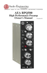
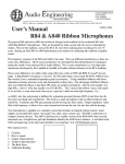
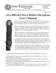
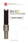
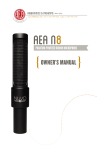
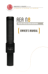
Audio Engineering Associates • STUDIO RIBBON MICS • MIC POSITIONERS • TALL STANDS • ACCESSORIES TRP - “The Ribbon Preamp” Operating Manual By Wes Dooley © May 2006 Basic Description The AEA TRP is a low-noise, high-gain, two-channel preamplifier for ribbon, moving coil, and tube microphones that do not use or want phantom power. With all of the features that a ribbon mic user ever needs, its minimum-path JFET design features ultra-high gain, and an 18,000 ohm input impedance. This brings out the best in all ribbon mics, especially those with narrow ribbons such as the RCA 77 and Royer Stereo, with their 1600 to 1800 ohm bass resonance peaks. When you plug a microphone into “The Ribbon Pre” you are taking a step back in time, to before phantom powering became ubiquitous. As you will discover in this manual and Appendixes A and B, it is not a good idea to use phantom power with mics that do not require it — not even with moving-coil mics, such as a Shure SM57. The TRP first stage electronics are minimal path, so there are no phantom power blocking capacitors. The pre-amp is protected, but without the extra coloration that results from using capacitors. Zener diodes are used instead to clamp down on external phantom power voltages while staying out of circuit for microphone level signals. First stage gain is set from + 6 to + 63 dB by a 12 position Grayhill switch. Another 21 dB of gain is available after the output level potentiometer. Internal audio switching for polarity reversal and highpass filters is handled by gold-contact Aeromat relays. These high-end components help keep the audio patch short and simple for best sound. Each channel features a three-LED level display. Green and red LEDs snap on to full brightness at -5 and +20 levels respectively. The amber LED increases in brightness between 0 and +20. Designed by Fred Forssell to handle extreme dynamics, the TRP recovers instantaneously from unexpected “solid red” overloads. Professional Neutrik 3 pin XLR and ¼ inch TRS phone connectors provide simultaneous balanced and unbalanced outputs. The balanced outputs deliver more than +28 dBu, and the unbalanced outputs exceed +22 dBu. All outputs will drive a 600 ohm load, but normal bridging loads of 5,000 ohms or more are recommended for maximum headroom. All inputs and outputs maintain proper polarity with each other and international standards. The 3 pin balanced mic input and line output connectors are wired Pin-2 + or high, and Pin-3 – or low. The unbalanced outputs have the tip as the high or + side, with the ring and barrel connected as the – or low side. 1029 N. Allen Ave., Pasadena, CA 91104 www.wesdooley.com Phone: (626) 798-9128 Fax: (626) 798-2378 An external desktop power supply with a grounded AC plug is used with the TRP, so hum fields can be kept away from the high-gain electronics. The power supply uses a seven pin circular DIN connector for its output, which is the same as the Symetrix 300 series. Additional Details A Grayhill rotary switch and high precision resistors set first stage gain to ensure exceptional gain accuracy. The match between channels is typically within 1/100 of a dB. 21 dB of additional second and third stage gain is provided after the 5,000 ohm level control pot. A typical operating position for this potentiometer would be around 2 o’clock. Except for fade outs, this control should not be used below its center position at 12 o’clock. The high-pass filter is intended to moderate the bass boost “proximity effect” inherent with a ribbon microphone when used up close. With very close talkers, this bass lift can become excessive to the point that speech intelligibility suffers. The balanced output stage drivers allow either Pin-3 or Pin-2 to be tied to pin one, with a reduction of headroom being the major performance penalty. To preserve maximum headroom however, we recommend only using the XLR outputs to drive balanced, floating, or differential inputs. The unbalanced phone jack outputs can drive either balanced or unbalanced loads and compared with the balanced outputs, provide 6 dB less gain. To minimize weight and preserve the TRP’s good looks, the half-rack wide by one rack unit high chassis is aluminum with a tough gray and black powder coat finish. A single line schematic and the front and rear panel markings are permanently laser engraved on the chassis. The power supply transformer is not designed to be used outdoors or in a wet environment. It has two 17.25 volt AC secondary windings, which are used within the TRP to provide three regulated DC voltages: bi-polar 18 volt currents are provided for the electronics and +12 volt currents for the Aeromat relays. Physical Specifications Electronics Specifications 83.5 dB of gain -129 EIN noise figure for 150 Ω source -0.5 dB at 160 kHz No phantom power, 18,000 ohm input impedance Green and Red LEDs indicates channel level Balanced XLR, and Unbalanced ¼ inch TRS outputs External Features Switched Gain and Continuous Level Controls Phase reverse and high-pass switches Finish: Gray and Black powder coated aluminum User Interface: Laser engraved legends and single line schematic on chassis External power supply for minimum noise i. Front view ii. Top view Audio Engineering Associates www.ribbonmics.com iii. Rear view B Power � � � � � � � Mic In � � � � A Mic In � No Phantom � ������ Dimensions Half-rack wide, one rack unit high (8.5” x 8.5” x 1.7”) Weight: Two pounds, power supply is 1.5 lbs “The Ribbon Pre” User Comments Allan Meyerson used The Ribbon Pre with AEA R84 mics while recording trombones for X Men III. Allan set up his pre-amps out on the stage with the mics and musicians. His only negative comment about using with the TRP was that he had to go into the studio to trim the gain. Shawn Murphy used the AEA TRP to record acoustic guitars for Disney’s Invincible at Sony Scoring. He used it with R84 mics and reported The Ribbon Pre was quiet, and sounded good, even at its highest gain settings. This is an important detail for Shawn, as he knows some pre-amp’s sound changes at higher gains. He ran the GAIN switch at maximum and the LEVEL pot at 12 o’clock, which provided 65.5 dB of channel gain with another 18.5 dB in reserve. Note from the Author: Much of what I know is because others have shared their experiences with me. Thank you for the opportunity to pass along that knowledge to you. A glossary that covers many of the technical audio terms used throughout this manual can be found at www.stereosoundbook.com. Appendix A Ribbon Mics and Mic Pre-amps © 2004, 2006 by Wes Dooley A RibbonMics.com Publication Studio ribbon microphones offer smooth and versatile performance that sounds good on a wide variety of music. They’ve proven themselves in daily use for more than 70 years. However, to achieve this great sound quality, using them with the right mic preamplifier is essential. This presupposes an understanding of how mic pre-amps interact with mics, in this case, with an emphasis on ribbon and other dynamic mics. Which mic pre-amps are best? Although this appendix will present some criteria for you to evaluate them, you should trust your ears and start listening carefully to mic pre-amps you own, borrow, or are considering purchasing. As you gain experience, you’ll discover that a quiet, distant, solo acoustic guitar, for example, will need 70 dB or more of clean, quiet gain. Older classics such as the ‘class A’ Neve units were designed to provide this gain. Likewise, many contemporary, stand-alone mic pre-amps sound good and can be ordered with extra gain. High performance, specialty pre-amps start at around $700, and choices multiply amazingly as you get to $1,000 per channel. Ribbon mics deliver extraordinary dynamic range, especially with percussion. Your experiences will tell you whether a specialty pre-amp might help you best capture the sounds you value. Mic pre-amps with transformers tend to have a sound of their own and lower input impedance. Transformerless designs tend to be more neutral and open sounding, generally are quieter, and have higher input impedance. The input impedance should be at least 1,000 ohms for ribbon mics, although 1,500 ohms is better. The lower range of impedances influences wider ribbons less, such as those found in AEA and Coles mics. Narrower ribbons, such as in the RCA 77 and the Speiden/Royer stereo mics, are more susceptible. Ribbon microphones with integrated, DC-powered active electronics, such as the old Cambridge or the new Royer P48 powered ribbon mics, reduce the influence of a mic pre-amp’s input impedance. Transformers are still used between the ribbon and the internal electronics, but these internal electronics keep the recording electronics from being affected by a ribbon’s low frequency resonances. As always with P48 powering, the 6,800 ohm current limiting resistors place a limit on the maximum current or voltage available. Ribbon mics have the potential, especially on percussion, for handling extreme transients and dynamic ranges. Thus in many cases it is better to use a ribbon mic with usercontrolled external electronics. Completely transformer-less ribbon mic signal chains are possible, but their current requirements would be high enough that P48 powering would be impractical. Mic output loading is another term for the interaction between a mic’s output impedance and a mic pre-amp’s input impedance. Richard Werner of RCA published an AES paper in 1955 showing that the overall frequency response is altered by this interaction. He measured an RCA 77’s impedance variation with frequency, and an RCA mic pre-amp’s input impedance at the same frequencies. His paper demonstrates how this changes the overall frequency response. The nominal source impedance of a balanced output professional mic can be as low as 20 ohms, is typically from 150 to 300 ohms, and occasionally is as high as 600 ohms. A balanced low impedance design minimizes hum pickup, and reduces high frequency loss and slew rate limiting caused by the higher capacitance of longer mic cables. Mics are not designed to drive a matching load. If your mic’s output impedance is 300 ohms and the pre-amp’s input load is 300 ohms, you‘re attenuating the mic’s signal by six dB. Raising the input impedance to 2700 ohms, reduces that attenuation to one dB, and increases the system’s signal to noise factor by five dB. Mic output and pre-amp input impedances can vary with frequency, sometimes significantly. Richard Werner’s AES paper documented a worse case scenario: He paired a 250 ohm output RCA 77D, narrow ribbon mic, with the 1,500 ohm input of a transformer-coupled tube mic pre-amp. The mic’s nominal 250 ohm output impedance soared to 1300 ohms at its 50 Hz resonance. At this frequency the pre-amp’s nominal 1500 ohm input impedance sagged to around 600 ohms. The result was a deep hole in the bass response of this combination below 100 Hz. To hear a mic as its designer intended, the pre-amp’s input impedance should be at least 1,500 ohms and consistent across the audio band. Even in the ranges above and below the 20-20 kHz audio band, the input impedance should remain high, as out-of-band load changes can affect in-band sonics. A rule of thumb is that a mic’s load impedance should be five or more times the mic’s source impedance. For a 300 ohm mic, such as the Coles 4038, this would translate to a 1,500 ohm load. For a 150 ohm source mic, such as most Neumann mics, this would mean a minimum load of 750 ohms, however, higher is even better. Thus, microphone impedances and pre-amp loadings seem to be a perpetual source of confusion. Ideally the mic’s source impedance should be as low as practical, and the load impedance it feeds should be as high as possible. Microphone pre-amplifier input impedances have been at 1,000 ohms or above now for decades. (Although 19th century voice-powered carbon telephone transmitters had to be loaded into matching 600 receivers for maximum power transfer, even the BBC abandoned that approach well before the 20th century ended.) As mentioned above, with such low impedance loads, P48 phantom powered electronics run out of current at high sound pressure levels. With such mics, the sound can improve significantly if loaded into a higher input impedance. The lower pre-amp input impedance a mic must drive, the harder it has to work. For condenser mics or others with built in electronics, driving too low of a load impedance is heard as decreased headroom, increased distortion, and especially when driving long mic cables, as high frequency limiting at high SPL. With the recent resurgence in popularity of “vintage” equipment, some contemporary mic pre-amp manufacturers provide selectable mic input impedances, as if this is a useful feature or a wonderful effect. Unless you are working with antique 30 or 50 ohm microphones, however, it is neither. Impedance matching is bad for signal to noise, increases distortion, and reduces headroom. The 1955 STC 4038 30-ohm version, built for the BBC was the last major studio microphone designed to be operated into a matching load. More recent versions have a 300-ohm source impedance. Both the 30 and 300ohm versions, however, operate more efficiently with a bridging rather than a matching load, and the BBC has now recognized this. Studio mics are not designed to feed a matched impedance load. You don’t get the sound you paid for when you force your mic to operate into loads that are less than five to ten times their own source impedance. In 1985 AEA built a limited run of transformer-coupled, stereo mic pre-amps with 84 dB of gain. These pre-amps had a user adjustable input impedance switch so that different mics could achieve their best square wave response. A number of mic pre-amps now offer user adjustable input impedances. Such mic pre-amps can alter the load a mic drives in a variety of ways. These changes range from simply varying the resistive loading a mic must drive, to the complexity of changing the turns ratio (impedance transformation) of an input transformer, and / or its secondary loading. Changing the turns ratio and secondary loading of a mic input transformer, can change a mic’s sound on transients from dull, to open, to ringing. Mic pre-amp designers typically aim for transients that are neither over-damped, i.e. dull and lifeless, nor under-damped with excessive ringing. However these designers have no control over which mics their pre-amps will be used with. Thus the same mic, used with different pre-amps, can yield a quite different sound. Transformers, like ribbon mics, look simple, but are deceptively complicated. Here are five common and uncommon events that will change the sound of any transformer. 1. When the source impedance (the mic output in this case) changes 2. When the turns ratio is changed 3. When the load on the transformer’s output side (secondary) changes 4. When the audio is softer or louder than the transformer’s linear operating range 5. If DC through a winding magnetizes the core material and it becomes less linear These variables can alter a pre-amp’s overall sound in quite complex ways, both in the 20-20kHz audio-band frequency response, and the frequency response above and below these points. Interestingly enough, changes in the out-of-band response will impact a pre-amp’s sound, especially with regards to transient response. As with any signal processing, the judgment is yours whether this is a change for the better or worse. To summarize everything above, the most relevant aspects of a mic pre-amp’s input impedance are: 1. How does it change the useable output level and linearity of a mic? 2. How does it alter the frequency and transient response of its mic? For more than forty years, I’ve listened to, set up, used, repaired and manufactured ribbon mics. The RCA-44 and RCA-77, among others, were the high performance standard when I was young and began being supplanted by moving coil and condenser mics as I learned my craft. More recently ribbon mics have enjoyed a renaissance. Throughout all these years, however, a number of competent audio engineers have continued to use them daily. Why? Because they deliver a warm, flattering sound in a wide range of situations that cause them to be the mic of choice for engineers, producers and musicians. Appendix B The Perils of Phantom Power © 2006 by Wes Dooley A RibbonMics.com Publication Phantom powering was developed in the mid 1960’s to power transistorized condenser mics without having to use special cables back to the power supply. Parallel powering, also known also as “AB” or “T” powering, was first introduced by Neumann, but they soon transitioned to 48 volt phantom powering. Schoeps, AKG and Sennheiser all soon developed transistorized condenser mics using some form of parallel or phantom power. The term “Phantom” is meant to reassure us that the operating current feeding a “phantom powered” to the condenser mic is “invisible” to ordinary tube, dynamic, and ribbon mics. This “invisible” power source was designed to not affect any balanced mics that might accidentally be plugged into phantom power. For convenience here I will refer to the microphone’s balanced modulation output pins as two and three, and the ground pin as one. We will ignore earlier microphone connectors and their pin numbering schemes. Phantom power was a big improvement over parallel (AB or T) powering. Parallel powering applies 12 volts of very clean DC to the two signal pins of a mic’s balanced output. Other mic types that have accidental encounters with parallel powering are unlucky. A DC voltage across pins two and three of any tube, moving coil, or ribbon mic that uses an output transformer changes the transformer’s magnetic performance and will permanently change the sound of that mic. This is a permanent change, even after the voltage is removed, unless the transformer can be demagnetized. 12 volts across pins two and three of a moving coil or ribbon mic tries to turn it into a subwoofer. An SM57 diaphragm will survive this sort of abuse, but a ribbon will snap in two as it accelerates out of the gap. Once the 12 volts is removed the SM57 will now sound subtly different, as it is a major event to magnetize a mic’s output transformer. This holds true whether the mic is a Neumann U 47 tube or KM 84 FET mic. A ribbon mic will sound drastically differently: it will be silent! The essence of phantom power is that there is no voltage differential between pins two and three of the balanced mic circuit. Phantom powered mics are designed to draw the same amount of current in each wire of the balanced twisted pair. Thus the voltage drop across each of the two feed resistors and modulation conductors in the cable is identical. Because there is no difference between the voltages on pins two and three, phantom power is “invisible” to the mic’s balanced audio output With both signal leads at the same potential, other mic types can be connected to a balanced phantom-powered input without damage. This assumes that the phantom power circuit is symmetrical and “floating” with no DC connection from either pin two or three of the modulation leads to the pin one ground reference. Perfect cables are assumed, because a short from either pin two or three to pin one will apply 48 volts DC across a mic’s output and the problems are then the same as applying parallel power to a mic. To further complicate the issue, any dirt or corrosion on the pins of the connector also can add resistance and unbalance the equality of the voltage seen by the microphone, and introduce similar problems. The term “phantom” originated in telephone systems, and referred to a method of separately ringing three telephones on a common two-wire line. Around 1970, Gotham Audio Corporation, the exclusive U.S. Neumann importer, applied to register the word “phantom” and “phantom powering” as U.S. trademarks, both of which were granted in 1971. Thus other terms such as “simplex” or “X/Y” powering were sometimes used as alternative descriptions for “phantom” until Gotham Audio allowed their trademarks to expire. Phantom powering was first standardized in Germany as DIN 45596 in 1973. This defines the powering of a single mic, but does not describe or limit the circuit configuration of the mic, which has remained the exclusive responsibility of the manufacturer. The two most important specifications for phantom powering are the supply voltage and the value of the feed resistor[s]. The most common voltage is 48 volts. It is for historical reasons that this voltage is so high. Neumann’s first phantom powered miniature mics, their KM80 series, used this 48 volt current to directly supply the capsule’s polarizing voltage. This reduced current consumption to less than 1 mA and simplified their circuitry by eliminating an internal DC-to-DC converter. For a number of reasons, using such a high voltage today would no longer be a designer’s first choice. However the proposal for 24 volt phantom powering arose too long after 48 volt phantom powering became a defacto standard, and is no longer being advocated. An alternate P12, 12 volt phantom powering standard exists, primarily for battery-operated equipment, but sees far less use than the P48, 48 volt standard. The value given for “maximum current” indicates the current per mic a phantom supply must be able to deliver for it to be in compliance with the standard. The actual current drawn depends on the design of the mic’s electronics and is normally smaller. The voltage drop across the phantom supply’s feed resistors is proportional to the current flowing through them. Thus the actual voltage between pins two and three of a mic’s modulation leads and pin one can vary considerably. A very low current design such as the Neumann KM80s, which draw only 0.4 mA and need a high voltage for capsule polarization, develops almost no IR drop across the P48 supply’s typical 6.81 K resistors. Alternately an AKG C451E uses an internal Zener diode to pull enough current through these 6.81K resistors to bring the voltage on pins two and three down to around 9 volts referenced to pin one. Some electronics such as the Neumann TLM 170 initially need quite a bit of current during their turn on period to achieve operating stability, and then pull less current during normal operation. The voltage source for a phantom power supply is supposed to be stable and have negligible internal resistance. Many phantom power supplies on the market though, including some from well-known manufacturers, add additional “current limiting” resistors of several thousand Ohms. This is safer than with old Stewart 48 volt phantom supplies, which used a non-standard lower resistance value. AKG C451 mics used with these supplies would self-destruct from that much current. Whether these situations resulted from errors or just ignorance of the P48 standard, they create problems. An extra series resistance in the supply will cause the supply voltage to sag unacceptably as more or higher current mics are connected. Until around 1979 the P48 standard only required 2 mA to be available per mic. This was enough for the earliest phantom powered mics as they typically only used a single field effect transistor. However this means that an old phantom power supply might not supply enough current to operate all P48 microphones. For over 25 years now the maximum allowable current has been 10 mA per mic. Retrospectively, a value of 7 mA maximum per mic might make more sense, as this is the point at which the maximum power is delivered to the condenser mic. But some reserve capacity was desired, and some mics actually draw 10 mA. (Chris Woolf has published specifications for most of the microphones on the world market in his Mic Data Book.) You might think all current P48 phantom supplies would be built to power all P48 microphones properly — that they meet the standard and are capable of delivering 10 mA of current per input from a 48 + 2 volts supply. You would be wrong, however, because some manufacturers are not committed to building adequate phantom powering into their mixers and mic pre-amps. Their primary weak points are supply voltages that are too low and/or an insufficient current capability. The presence of such nonstandard products on the market means that not all microphones you hear are performing at their best. Not all the details of DIN 45596 have been included here. The details of the standard were only published in English as IEC standard 268-15A in 1981. Since a number of phantom powered products are not built to meet this standard, it seems apparent that even today these P48 phantom powering standards are not yet widely enough known by all microphone and pre-amp manufacturers — or worse yet, maybe they simply don’t care. After all, it is sad but true that commerce often drives technology, rather than vice versa. Notes from Joerg Wuttke, director of engineering for Schoeps microphones: “Although improvements are always desirable, right now it would be major progress if all manufacturers would implement even the simplest form of phantom powering correctly (a stable voltage source plus two resistors). You can find further details in my paper “The Feeble Phantom,” which can be downloaded from http://www.reddingaudio.com/schoeps/the_feeble_phantom.pdf. The phantom power standard has never said anything up to now about the effect that a mic connected to one input might have on adjacent input channels. In theory there should be no such effect at all since a voltage source has zero source impedance. But evidence could be brought to show that such problems sometimes do occur in practice.” Other Products by Audio Engineering Associates: RCA Working Reproduction Microphones and replacement parts AEA R44C Microphone - Museum Quality Reproduction Our tribute to the classic RCA 44B using New Old Stock ribbon material AEA 44CX Microphone 6db more output for critical digital recordings AEA 44CNE Microphone Based on RCA LTD production - the same sound but easier to build AEA Ribbon Microphones R84 - Studio Ribbon Mic R88 - Stereo Ribbon Mic R92 - Studio Ribbon Mic specifically designed for close micing and guitar Modular Studio Microphone Stands and Booms Since 1983 we have imported and serviced the Coles 4038 studio ribbon microphone and the 4104B, “lip” mic for voice-over work in high noise environments. We sell and service the mics and stock replacement parts. In North America we also represent CB Electronics, a leading worldwide supplier of machine control equipment to the sound-for-picture industry. Their products specialize in professional control of and translation between bi-phase, 9-pin serial and time code machines. Their SR line provides low cost multiple machine remote controls for RS-422, Sony, and Tascam DA88 protocol machines. Audio Engineering Associates • STUDIO RIBBON MICS • MIC POSITIONERS • TALL STANDS • ACCESSORIES 1029 N. Allen Ave. Pasadena, CA 91104 Phone: (626) 798-9128 Fax: (626) 798-2378 www.ribbonmics.com