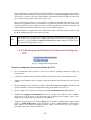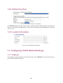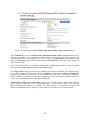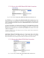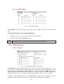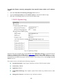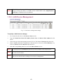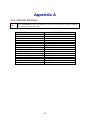
1
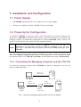
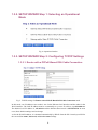
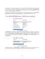
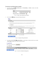
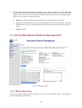
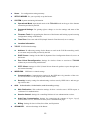
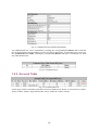
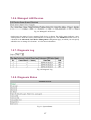
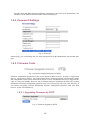
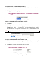
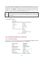
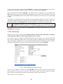
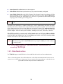
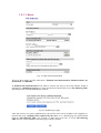
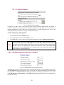
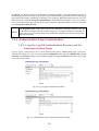
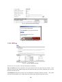
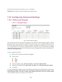
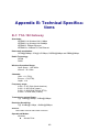
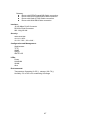
TYA-192 Wi-Fi Pay Terminal
Application Manual
Version: 1.0
Last Updated: 111/12/20088
Table of Contents
1. Installation and Configuration............................................................................................ 1
1.1. Power Supply.......................................................................................................... 1
1.2. Preparing for Configuration ..................................................................................... 1
1.2.1. Connecting the Managing Computer and the TYA-192 ................................. 1
1.2.2. Changing the TCP/IP Settings of the Managing Computer............................ 2
1.3. Configuring the TYA-192......................................................................................... 2
1.3.1. Entering the User Name and Password ........................................................ 2
1.3.2. SETUP WIZARD Step 1: Selecting an Operational Mode ............................. 4
1.3.3. SETUP WIZARD Step 2: Configuring TCP/IP Settings.................................. 4
1.3.4. SETUP WIZARD Step 3: DHCP Server Settings........................................... 6
1.3.5. SETUP WIZARD Step 4: Configure IEEE 802.11 Settings ............................ 7
1.3.6. SETUP WIZARD Step 5: Configuring the Billing Setting................................ 7
1.3.7. SETUP WIZARD Step 6: System Setting. ..................................................... 8
1.3.8. Configuring User Authentication Settings ...................................................... 8
1.4. Using Web-Based Network Management.............................................................. 11
1.4.1. Menu Structure ........................................................................................... 11
1.4.2. Save, Save & Restart, and Cancel Commands ........................................... 13
1.4.3. Home and Refresh Commands ................................................................... 14
1.5. Seeing Status........................................................................................................ 14
1.5.1. Associated Wireless Clients ........................................................................ 14
1.5.2. Authenticated Users.................................................................................... 14
1.5.3. Account Table ............................................................................................. 15
1.5.4. Amount Log................................................................................................. 16
1.5.5. Session List................................................................................................. 16
1.5.6. Managed LAN Devices ............................................................................... 17
1.5.7. Diagnosis Log ............................................................................................. 17
1.5.8. Diagnosis Status ......................................................................................... 17
1.6. System.................................................................................................................. 18
1.6.1. Specifying Operational Mode ...................................................................... 18
1.6.2. Password Settings ...................................................................................... 19
1.6.3. Firmware Tools ........................................................................................... 19
1.6.4. Setting Time Zone....................................................................................... 24
1.6.5. Location Information.................................................................................... 24
1.7. Configuring TCP/IP Related Settings .................................................................... 24
1.7.1. Address....................................................................................................... 24
1.7.2. DHCP Server .............................................................................................. 27
1.7.3. Zero Client Reconfiguration......................................................................... 28
1.7.4. PPTP Client ................................................................................................ 29
1.8. Configuring Wireless Settings ............................................................................... 29
1.8.1. Communication ........................................................................................... 29
1.8.2. Security....................................................................................................... 30
1.9. Configuring AAA (Authentication, Authorization, Accounting) Settings 31
1.9.1. Web Redirection ......................................................................................... 31
1.9.2. Authentication Session Control ................................................................... 35
1.9.3. Authentication Page Customization............................................................. 36
1.9.4. Billing .......................................................................................................... 38
1.10. Configuring Advanced Settings ........................................................................... 39
1.10.1. Filters and Firewall .................................................................................... 39
1.10.2. Management ............................................................................................. 41
1.10.3. LAN Device Management ......................................................................... 43
A-1: Default Settings .................................................................................................... 44
A-2: LED Definitions..................................................................................................... 45
A-3: Rear Panel ........................................................................................................... 45
B-1: TYA-192 Gateway ................................................................................................ 46
i
ii
1. Installation and Configuration
1.1. Power Supply
1.
The TYA-192 is powered by DC 5V / 8A and DC 12V / 6A power supply.
2.
After power is supplied, check the “POWER” LED on (Green light).
1.2. Preparing for Configuration
To configure a TYA-192, a managing computer with a Web browser is needed. For first-time configuration of a TYA-192, an Ethernet network interface card (NIC) should have been installed in the
managing computer. For maintenance-configuration of a deployed TYA-192, either a wireless computer or a wired computer can be employed as the managing computer.
NOTE:
If “Opera” browser is used to configure an TYA-192, click the menu item File, click
Preferences... click File types, and edit the MIME type, text/html, to add a file extension “.sht” so that Opera can work properly with the Web management pages of the
TYA-192.
Since the configuration/management protocol is HTTP-based, you have to make sure that the IP address of the managing computer and the IP address of the managed TYA-192 are in the same IP subnet
(the default IP address of an TYA-192 is 192.168.0.1 and the default subnet mask is 255.255.255.0.)
1.2.1. Connecting the Managing Computer and the TYA-192
To connect the managing computer and the TYA-192 for first-time configuration, you have two
choices as illustrated in Fig. 1.
Crosss-over
Ethernet cable
Normal
Ethernet cable
Managing
Computer
Normal
Ethernet cable
Ethernet
Hub / Switch
Managed
TYA-192
Fig. 1. Connecting a managing computer and an TYA-192 via Ethernet.
1
You can use either a cross-over Ethernet cable (included in the package) or a switch/hub with 2
straight-through Ethernet cables.
NOTE:
One connector of the Ethernet cable must be plugged into the LAN Ethernet port of the
TYA-192 for configuration.
1.2.2. Changing the TCP/IP Settings of the Managing
Computer
Use the Windows Network Control Panel Applet to change the TCP/IP settings of the managing
computer, so that the IP address of the computer and the IP address of the TYA-192 are in the same
IP subnet. Set the IP address of the computer to 192.168.0.xxx.
NOTE:
For some versions of Windows, the computer needs to be restarted for the changes of
TCP/IP settings to take effect.
1.3. Configuring the TYA-192
The TYA-192 is DHCP server enabled by default. After the IP addressing is configured, launch a
Web browser on the managing computer. Then, go to “http://192.168.0.1” to log on to the
TYA-192 for Web-based management.
TIP:
For maintenance configuration, the TYA-192 can be reached by its host name using a
Web browser. For example, if the TYA-192 is named “AP”, you can use the URL
“http://AP” to access the Web-based management interface of the TYA-192.
1.3.1. Entering the User Name and Password
Before the Home page is shown, you will be prompted to enter the user name and password to gain
the right to access the Web-based Network Manager. For first-time configuration, use the default user
name “root” and default password “root”, respectively.
Fig. 2. Entering the user name and password.
2
NOTE:
It is strongly recommended that the password be changed to other value for security reasons. (See Section 1.6.2 for more information).
Fig. 3. The Home Page.
On the Home page, click the SETUP WIZARD to quickly change the configuration of the gateway.
3
1.3.2. SETUP WIZARD Step 1: Selecting an Operational
Mode
Fig. 4. Operational modes.
1.3.3. SETUP WIZARD Step 2: Configuring TCP/IP Settings
1.3.3.1. Router with a PPPoE-Based DSL/Cable Connection
Fig. 5. TCP/IP settings for Router with a PPPoE-Based DSL/Cable Connection mode.
In this mode, two IP addresses are needed—one for the Ethernet LAN interface and the other for the
WAN interface. The LAN IP address must be set manually to a private IP address, say 192.168.0.xxx.
The default LAN IP address is 192.168.0.1 and the default subnet mask is 255.255.255.0. In most
cases, these default settings need no change.
As for the WAN IP address, it is obtained automatically by PPPoE from the ISP. Consult your ISP for
the correct User name, Password, and Service name settings.
4
The Trigger mode setting specifies the way a PPPoE connection is established. Your PPPoE connection can be established and torn down manually (Manual) by clicking the Connect and Disconnect
buttons on the Start page, respectively. Or you can choose to let the device automatically (Auto) establish a PPPoE connection at boot-up time. In Auto mode, if the connection is disrupted, the device
will try to re-establish the broken connection automatically.
1.3.3.2. Router with a DHCP-Based DSL/Cable Connection
Fig. 6. TCP/IP settings for Router with a DHCP-Based DSL/Cable Connection mode.
In this mode, two IP addresses are needed—one for the Ethernet LAN interface and the other for the
WAN interface. The LAN IP address must be set manually to a private IP address, say 192.168.0.xxx.
The default LAN IP address is 192.168.0.1 and the default subnet mask is 255.255.255.0. In most
cases, these default settings need no change.
As for the WAN IP address, it is obtained by DHCP from the ISP. The Trigger mode setting affects
the behavior of the DHCP client of the Router. In Auto mode, you don’t have to worry about the
DHCP process; the device takes care of everything. In Manual mode, there are two buttons on the
Start page for you to manually release an obtained IP address (Release) and re-obtain a new one from
a DHCP server (Renew).
1.3.3.3. Router with a Static-IP DSL/Cable Connection
Fig. 7. TCP/IP settings for Router with a Static-IP DSL/Cable Connection mode.
5
In this mode, two IP addresses are needed—one for the Ethernet LAN interface and the other for the
WAN interface. The LAN IP address must be set manually to a private IP address, say 192.168.0.xxx.
The default LAN IP address is 192.168.0.1 and the default subnet mask is 255.255.255.0. In most
cases, these default settings need no change.
As for the WAN IP address, it must be manually set. Consult your ISP for the correct IP address,
Default Router, Subnet mask, Primary DNS server, and Secondary DNS server settings.
1.3.4. SETUP WIZARD Step 3: DHCP Server Settings
Fig. 8. DHCP Server Setting
The TYA-192 can automatically assign IP addresses to client computers by DHCP. You can specify
the first IP address that will be assigned to the clients and the number of allocatable IP addresses. In
most cases Default gateway and Primary DNS server should be set to the IP address of the Router’s
LAN interface (e.g., the default LAN IP address is 192.168.0.1 and the Subnet mask is set to
255.255.255.0.)
Fig. 9. DHCP Relay Setting
When functionality is set to DHCP Relay, the TYA-192 would not assign any IP address to the clients. It forwards the received DHCP requests from the clients to the designate DHCP server.
6
1.3.5. SETUP WIZARD Step 4: Configure IEEE 802.11 Settings
Fig. 10. IEEE 802.11b communication settings.
The number of available RF channels depends on local regulations; therefore you have to choose an
appropriate regulatory domain to comply with local regulations. The SSID of a wireless client computer and the SSID of the wireless access Router must be identical for them to communicate with each
other.
1.3.6. SETUP WIZARD Step 5: Configuring the Billing Setting
Fig. 11. Configure Billing Steetings
7
There are two service plans: Time to Finish and Accumulation.
Time to Finish means the subscriber can access Internet only one time with one account. Once
subscriber login, the pre-defined usage time will start until run out even the subscriber stop to access
the Internet before run out.
Accumulation means the subscriber can access Internet several times with one account. The system
can keep and accumulate every single usage time until the pre-defined usage time run out.
There are four selections for price plan: A, B, C, and others.
Expiration is the setting for the pre-defined usage duration time.
1.3.7. SETUP WIZARD Step 6: System Setting.
Fig. 12. Configure System administrator and Time Settings
1.3.8. Configuring User Authentication Settings
The TYA-192 supports both Web redirection-based and non-802.1x-based user and IEEE
802.1x-based user authentication.
After the IP addressing settings have been set using SETUP WIZARD, you have to configure Web
redirection settings and/or IEEE 802.1x settings for wireless user authentication.
When both Web redirection and IEEE 802.1x are enabled, the authentication process will first tried
8
IEEE 802.1x and then Web Redirection. In this way, the wireless access router can serve both IEEE
802.1x-enabled and IEEE 802.1x-disabled wireless users.
1.3.8.1. Web Redirection
To setup Web redirection-based user authentication, go to the AAA
Web Redirection section for
configuration. There are three combinations for Web Redirection and Authentication method:
1. Enable with Authentication – Enable both Web-Redirection and user Authentication mechanism.
Fig. 13. Web redirection settings – Enable with Authentication
1.1.
Encryption Method:
1.1.1.
401 Authorization: Logon page on Pop-up window.
1.1.2.
CGI with Plain Code: Logon page on web browser, username/password without
encryption (plain text).
1.1.3.
CGI with Base64: Logon page on web browser, username/password with
Base64 encryption.
1.1.4.
CGI with SSL: Logon page on web browser, username/password with SSL encryption.
2. Enable without Authentication – Enable only the Web-Redirection, but disable the user Authentication mechanism. User will automatically redirect to the destination web page if the URL indicated.
Fig. 14. Web redirection settings – Enable without Authentication
3. Disable – Disable all Web-Redirection mechanisms.
1.3.8.2. Local Authentication Sever
The TYA-192 supports the local Authentication Sever for some hotspot venues where Billing server(s)
is difficult to be implemented. The local Authentication Server contains the built-in database for 2,000
user entries.
9
To setup the Local Authentication method:
1.
Go to the section AAA
Web Redirection, in ‘Functionality’ of ‘Basic’ column, select ‘Enabled with Authentication’.
Fig. 15. Enable with Authentication Settings
2.
Go to the AAA
Billing to setup the billing information.
Fig. 16. Setup the billing information
3.
Go to the section STATUS
Account Table to see the history of the latest 300 user accounts.
“Clean Table’ button uses to remove all user accounts.
Fig. 17. Local User Database Management
10
4.
All the status of generated local users will show in the ‘Account Table List’. The account table
list also includes the accounts which are randomly generated by the gateway as using the control
keypad. The user must use the generated username and password for access logon process.
There are 3 type status of each user account:
Register: to show the generated user who has not yet logon and been activated.
Active: the generated user who has successfully logon and access the Internet. The MAC
address and Login Time of the activated user will be also shown while user has been activated.
Logoff: Log off.
1.4. Using Web-Based Network Management
Fig. 18. The Home page.
1.4.1. Menu Structure
The left side of the start page contains a menu for you to carry out commands. Here is a brief description of the hyperlinks on the menu:
11
Home.
SETUP WIZARD. For you to quickly set up the Router.
SYSTEM. System monitoring information.
For configuration setting summary.
Operational Mode. Operational mode of the TYA-192 based on the type of the Internet
connection provided by the ISP.
Password Settings. For gaining right to change or view the settings and status of the
Router.
Firmware Tools. For upgrading the firmware of the Router and backing up and restoring
configuration settings of the Router.
Time Zone. Time zone and SNTP (Simple Network Time Protocol) server settings.
Location Information
TCP/IP. TCP/IP-related settings.
Address. IP addressing settings for the Router to work in the TCP/IP networking world,
or user name and password provided by the ISP.
DHCP Server. Settings for the DHCP (Dynamic Host Configuration Protocol) server on
the Router.
Zero Client Reconfiguration. Settings for wireless clients to associate to TYA-192
without any network setting modification.
PPTP Client. Settings for VPN (Virtual Private Network) packets to pass through internet-internet boundary.
WIRELESS.
IEEE 802.11-related settings.
Communication. Communication settings for the IEEE 802.11b/g interface of the wireless access Router to work properly with wireless clients.
Security. Security settings for authenticating wireless users by IEEE 802.1x and encrypting wireless data.
AAA.
Authentication, Authorization, and Accounting settings.
Web Redirection. Web redirection settings for how a wireless user’s HTTP request is
“redirected” for authentication.
Session Control. Settings for controlling lifetimes of user authentication sessions.
Auth Page Customization. Settings for customizing the contents of log-on, log-off,
authentication success, and authentication failure authentication pages.
Billing. Settings for Service Plan, Price Plan, and Expiration.
ADVANCED.
Advanced settings of the Router.
12
Filters & Firewall. Packet filtering and firewall settings for user access control and protection from hacker attacks from the Internet, respectively.
Management. Web-based management types, UPnP, and SNMP settings.
LAN Device Management. Settings for the Router to know what LAN devices it has to
manage.
Status. System monitoring information.
Associated Wireless Clients. Display the status of all wireless clients who associated
to TYA-192.
Authenticated Users. Display the status of the users who have been authenticated by
TYA-192. Authenticated users can be also forced terminated in this table.
Account Table. Generate the new users in the authentication mode by Local Accounts.
Billing ticket will be also generated and printed by pressing ‘Generator’ button on this
page.
Amount Log. Display the statistics for the account table.
Session list. Display the status of session traffic of TYA-192.
Managed LAN Devices. Display the status of local LAN devices which connected to
TYA-192.
Diagnosis Log. Display the status log between control board and gateway.
Diagnosis Status. Display the system status.
1.4.2. Save, Save & Restart, and Cancel Commands
Fig. 19. Save, Save & Restart, and Cancel.
At the bottom of each page, there are up to three buttons—Save, Save & Restart, and Cancel. Clicking Save stores the settings changes to the memory of the Router and brings you back to the start page.
Clicking Save& Restart stores the settings changes to the memory of the Router and restarts the
Router immediately for the settings changes to take effect. Clicking Cancel discards any settings
changes and brings you back to the start page.
If you click Save, the start page will reflect the fact that the configuration settings have been changed
by showing two buttons—Restart and Cancel. Clicking Restart restarts the Router for the settings
changes to take effect.
13
1.4.3. Home and Refresh Commands
Fig. 20. Home and Refresh.
At the bottom of each status page that shows read-only information, there are two buttons—Home
and Refresh. Clicking Home brings you back to the start page. Clicking Refresh updates the shown
status information.
1.5. Seeing Status
1.5.1. Associated Wireless Clients
Fig. 21. Status of associated wireless clients.
On this page, the status information of each associated client, including its MAC address, IP address,
user name (if the client has been IEEE 802.1x authenticated), number of bytes it has sent, number of
bytes it has received, and the time of its last activity, is shown.
1.5.2. Authenticated Users
Fig. 22. Authenticated users.
On this page, the status information of each authenticated user, including its current idle time, user
name, IP address, MAC address, and status, is shown. In addition, you can click the Detail link in the
Statistics column to see more detailed statistics information, such as Input packets, Output packets,
Input bytes, and Output bytes.
14
Fig. 23. Authenticated user detailed information.
Any authenticated user can be terminated by clicking the corresponding Terminate link so that this
user is blocked from using networking services provided by the Router. A terminated user is moved to
the Terminated Users Table. Clicking the corresponding Release link puts a terminated user back
into authenticated state.
Fig. 24. Terminated users.
1.5.3. Account Table
Fig. 25. Account Table List
On this page, all the local under registered in local user database are shown. A activated user is identified by its MAC address, login time and the ‘Active’ under the ‘Status’ column.
15
1.5.4. Amount Log
Fig. 26. Amount Log List
◆ Total Amount:Total amount of money currently in the coin box
◆ Coinbox Pulled Value:Total amount of money at last pulled coin box
◆ Amount:Each transaction amount
◆ Date/Time:transaction time
1.5.5. Session List
Fig. 27. Latest outgoing user traffic sessions.
Fig. 28. Latest incoming user traffic sessions.
On this page, latest 50 outgoing and 50 incoming user traffic sessions are shown for monitoring network activity.
16
1.5.6. Managed LAN Devices
Fig. 29. Managed LAN devices.
On this page, the status of every managed LAN device is shown. The Offline status indicates a nonworking device while the Online status indicates a working device. The Add Device button serves as
a shortcut to the Advanced, LAN Device Management configuration page, on which you can specify
which devices to manage. See Section 1.10.3 for more information.
1.5.7. Diagnosis Log
Fig. 30. Diagnosis Log.
1.5.8. Diagnosis Status
Fig. 31. System Status.
17
◆ No account:Sale accounts over 300 or Disabled Authentication
◆ Reserved:Reserved
◆ No WAN:Internet Access failure
◆ Printer Problem:No paper、Printer malfunction、Lack of paper
◆ Coin box full:Coin box full
◆ Coin box steal:Coin box pulled over 25 seconds
◆ Coin machine error:Coin mechanism malfunctions
◆ Keypad error:Stuffed keypad
◆ RS232 error: communication failure between Control Board and Gateway
1.6. System
1.6.1. Specifying Operational Mode
Fig. 32. Operational modes.
On this page, you can specify the operational mode for the Router. Currently, 5 modes are available:
Router with a PPPoE-based DSL/Cable Connection. In this mode, the Router assumes
that a DSL or cable modem is connected to its Ethernet WAN interface. The client computers
can therefore share this DSL/cable-based Internet connection by the NAT server functionality.
The IP address of the Ethernet WAN interface is obtained automatically by PPPoE from the ISP.
Router with a DHCP-based DSL/Cable Connection. In this mode, the Router assumes
that a DSL or cable modem is connected to its Ethernet WAN interface. The client computers
can therefore share this DSL/cable-based Internet connection by the NAT server functionality.
The IP address of the Ethernet WAN interface is obtained automatically by DHCP from the ISP.
Router with a Static-IP DSL/Cable Connection. In this mode, the Router assumes that a
DSL or cable modem is connected to its Ethernet WAN interface. The client computers can
18
therefore share this DSL/cable-based Internet connection by the NAT server functionality. The
IP address of the Ethernet WAN interface must be manually set.
1.6.2. Password Settings
Fig. 33. Password.
On this page, you could change the user name and password of the administrator and account manager.
1.6.3. Firmware Tools
Fig. 34. Firmware management protocol setting.
Firmware management operations for the access Router include Firmware Upgrade, Configuration
Restore, Configuration Backup, and Configuration Reset. Firmware upgrade, configuration backup,
and configuration restore can be achieved via HTTP or TFTP. The HTTP-based way is suggested because it’s more user-friendly. However, due to different behavior of different Web browser versions,
HTTP-based firmware management operations may not work properly with some Web browsers. If
you cannot successfully perform HTTP-based firmware management operations with your Web
browser, try the TFTP-based way.
1.6.3.1. Upgrading Firmware by HTTP
Fig. 35. Firmware upgrade by HTTP.
19
To upgrade firmware of the access Router by HTTP:
1.
Click Browse and then select a correct firmware .bin file. The firmware file path will be shown
in the Firmware file name text box.
2.
Click Upgrade to begin the upgrade process.
1.6.3.2. Backing up and Restoring Configuration Settings by
HTTP
Fig. 36. Configuration backup by HTTP.
To back up configuration of the access Router by HTTP:
1.
Click Back Up.
2.
You’ll be prompted to open or save the configuration file. Click Save.
3.
The configuration file is named by the TYA-192’s MAC address. For example, if the
TYA-192’s MAC address is 00-01-02-33-44-55, the configuration backup file should be
“000102334455.hex”. Don’t change the configuration file name in the Save As dialog box. Select a folder in which the configuration file is to be stored. And then, click Save.
NOTE:
The procedure may be a little different with different Web browsers.
Fig. 37. Configuration restore by HTTP.
To restore configuration of the access Router by HTTP:
1.
Click Browse and then select a correct configuration .hex file. You have to make sure the file
name is the access Router’s MAC address. The firmware file path will be shown in the Firmware file name text box.
2.
Click Restore to upload the configuration file to the access Router.
1.6.3.3. Upgrading Firmware by TFTP
Fig. 38. TFTP server settings.
20
When use TFTP as the firmware management protocol, you can configure settings for the access
Router’s TFTP client to communicate with a TFTP server. If the TFTP client does not get a response
from the TFTP server within a period specified by the Timeout setting, it will resend the previous
request. The Max number of retries setting specifies the maximal number of resend before the TFTP
client stops communicating with the TFTP server.
Within the folder “Utilities” on the companion CD-ROM disk, we offered a TFTP server program
(TftpSrvr.exe) for firmware upgrade. Run this program on the computer that is to serve as a TFTP
server.
Fig. 39. Firmware upgrade by TFTP.
To upgrade firmware of the access Router by TFTP:
1.
Get a computer that will be used as a TFTP server and as a managing computer to trigger the
upgrade process.
2.
Connect the computer and one of the LAN Ethernet switch port with a normal Ethernet cable.
3.
Configure IP address of the computer so that the Router and the computer are in the same IP
subnet.
4.
On the computer, run the TFTP Server utility. And specify the folder in which the firmware files
reside.
5.
On the computer, run a Web browser and click the General, Firmware Upgrade hyperlink.
6.
Specify the IP address of the computer, which acts as a TFTP server. If you don’t know the IP
address of the computer, open a Command Prompt, and type IpConfig, then press the Enter key.
7.
Trigger the firmware upgrade process by clicking Upgrade.
Fig. 40. TFTP Server.
21
After the dialog box of the TFTP server program appears, be sure to specify the working folder
within which the downloaded firmware files reside and the Accept read requests check box of
TFTP Server is selected. Also, the LAN IP address of the Router and the IP address of the TFTP
server must be in the same IP subnet for TFTP to work.
Due to the unreliable nature of wireless media, it’s highly recommended that the TFTP server
and the to-be-upgraded wireless access Router be connected by Ethernet, and on the same LAN,
so that the upgrade process would be smooth. A failed upgrade may corrupt the firmware and
make the Router unstartable. When this occurs, call for technical support.
After the firmware is upgraded, be sure to delete the contents of the Web browser cache, so that
the Web management pages can be shown correctly.
TIP:
The firmware of a deployed access Router can also be upgraded remotely from the Internet. In this case, you must have configured the Router to be remotely manageable (see
Section 1.9.1.1) and adjust the Timeout and Max no. of retries settings of TFTP Server
for remote TFTP upgrade to succeed.
1.6.3.4. Backing up and Restoring Configuration Settings by
TFTP
Fig. 41. Configuration backup/restore.
To back up configuration of the access Router by TFTP:
1.
Get a computer that will be used as a TFTP server and as a managing computer to trigger the
backup process.
2.
Connect the computer and one of the LAN Ethernet switch port with a normal Ethernet cable.
3.
Configure the IP address of the computer so that the computer and the Router are in the same IP
subnet.
4.
On the computer, run the TFTP Server utility. Select the Accept write requests check box, and
specify the folder to which the configuration settings of the Router will be saved.
5.
On the computer, run a Web browser and click the SYSTEM\Firmware Tools hyperlink.
6.
Within the Configuration Backup/Restore section, specify the IP address of the computer,
which acts as a TFTP server. If you don’t know the IP address of the computer, open a Command Prompt, and type IpConfig, then press the Enter key.
7.
Trigger the backup process by clicking Back Up. The Router’s configuration settings will be
saved as “AaBbCcDdEeFf.hex” by the TFTP server, where “AaBbCcDdEeFf” is the Router’s
MAC address. For example, if the Router’s MAC address is 00-01-02-33-44-55, the configuration backup file will be “000102334455.hex”.
22
NOTE:
Remember to select the Accept write requests check box of TFTP Server.
To restore configuration of the TYA-192 by TFTP
1.
Get a computer that will be used as a TFTP server and as a managing computer to trigger the
restoring process.
2.
Connect the computer and one of the LAN Ethernet switch port with a normal Ethernet cable.
3.
Configure the IP address of the computer so that the computer and the Router are in the same IP
subnet.
4.
On the computer, run the TFTP Server utility. And specify the folder in which the configuration
backup file resides. A configuration backup file is named by the Router’s MAC address. For
example, if the Router’s MAC address is 00-01-02-33-44-55, the configuration backup file
should be “000102334455.hex”.
5.
On the computer, run a Web browser and click the General, Firmware Tools hyperlink.
6.
Within the Configuration Backup/Restore section, specify the IP address of the computer,
which acts as a TFTP server. If you don’t know the IP address of the computer, open a Command Prompt, and type IpConfig, then press the Enter key.
7.
Trigger the restoring process by clicking Restore. The Router will then download the configuration backup file from the TFTP server.
NOTE:
Make sure the file is a valid configuration backup file for the access Router.
1.6.3.5. Resetting Configuration to Factory Defaults
Fig. 42. Configuration reset.
Clicking the Reset button resets the device configuration to factory defaults.
WARNING: Clicking the Reset button will lose all your current configuration settings.
23
1.6.4. Setting Time Zone
Fig. 43. Time zone and time server settings.
The TYA-192 supports absolute system time by querying the SNTP (Simple Network Time Protocol)
time server specified by the Time server setting. And you should specify the Time zone according to
where you are.
1.6.5. Location Information
Fig. 44. Location Information Settings.
1.7. Configuring TCP/IP Related Settings
1.7.1. Address
The addressing settings depend on the operational mode of the TYA-192. Each operational mode requires different addressing settings.
24
1.7.1.1. Router with a PPPoE-Based DSL/Cable Connection
Fig. 45. TCP/IP settings for Router with a PPPoE-Based DSL/Cable Connection mode.
If the TYA-192 was set to be in Router with a PPPoE-Based DSL/Cable Connection mode, two IP
addresses are needed—one for the Ethernet LAN interface and the other for the WAN interface. The
LAN IP address must be set manually to a private IP address, say 192.168.0.xxx. The default LAN IP
address is 192.168.0.1 and the default subnet mask is 255.255.255.0. In most cases, these default settings need no change.
As for the WAN IP address, it is obtained automatically by PPPoE from the ISP. Consult your ISP for
the correct User name, Password, and Service name settings.
The Trigger mode setting specifies the way a PPPoE connection is established. Your PPPoE connection can be established and torn down manually (Manual) by clicking the Connect and Disconnect
buttons on the Start page, respectively. Or you can choose to let the device automatically (Auto) establish a PPPoE connection at bootup time. In Auto mode, if the connection is disrupted, the device
will try to re-establish the broken connection automatically.
Custom MAC Address of WAN Interface enables you to change the MAC address of the Ethernet
WAN interface. Therefore, if the ISP-provided DSL or cable modem works only with the
ISP-provided Ethernet card for a computer, the WAN interface of the Router can mimic the
ISP-provided Ethernet card by changing its MAC address to the Ethernet card’s MAC address.
25
1.7.1.2. Router with a DHCP-Based DSL/Cable Connection
Fig. 46. TCP/IP settings for Router with a DHCP-Based DSL/Cable Connection mode.
If the TYA-192 was set to be in Router with a DHCP-Based DSL/Cable Connection mode, two IP
addresses are needed—one for the Ethernet LAN interface and the other for the WAN interface. The
LAN IP address must be set manually to a private IP address, say 192.168.0.xxx. The default LAN IP
address is 192.168.0.1 and the default subnet mask is 255.255.255.0. In most cases, these default settings need no change.
As for the WAN IP address, it is obtained by DHCP from the ISP. The Trigger mode setting affects
the behavior of the DHCP client of the Router. In Auto mode, you don’t have to worry about the
DHCP process; the device takes care of everything. In Manual mode, there are two buttons on the
Start page for you to manually release an obtained IP address (Release) and re-obtain a new one from
a DHCP server (Renew).
‘Heartbeat for BigPond Cable’ is the settings for service of Telstra, Australia. Please consult the Telstra ISP for detail information.
Custom MAC Address of WAN Interface enables you to change the MAC address of the Ethernet
WAN interface. Therefore, if the ISP-provided DSL or cable modem works only with the
ISP-provided Ethernet card for a computer, the WAN interface of the Router can mimic the
ISP-provided Ethernet card by changing its MAC address to the Ethernet card’s MAC address.
1.7.1.3. Router with a Static-IP DSL/Cable Connection
Fig. 47. TCP/IP settings for Router with a Static-IP DSL/Cable Connection mode.
26
If the Router was set to be in Router with a Static-IP DSL/Cable Connection mode, two IP addresses are needed—one for the Ethernet LAN interface and the other for the WAN interface. The
LAN IP address must be set manually to a private IP address, say 192.168.0.xxx. The default LAN IP
address is 192.168.0.1 and the default subnet mask is 255.255.255.0. In most cases, these default settings need no change.
As for the WAN IP address, it must be manually set. Consult your ISP for the correct IP address,
Default Router, Subnet mask, Primary DNS server, and Secondary DNS server settings.
Custom MAC Address of WAN Interface enables you to change the MAC address of the Ethernet
WAN interface. Therefore, if the ISP-provided DSL or cable modem works only with the
ISP-provided Ethernet card for a computer, the WAN interface of the Router can mimic the
ISP-provided Ethernet card by changing its MAC address to the Ethernet card’s MAC address.
1.7.2. DHCP Server
1.7.2.1. Functionality
There are three mode of DHCP Server to be defined in ‘Functionality’: Disable, DHCP Server , and
DHCP Relay.
1.7.2.2. Basic
Fig. 48. Basic DHCP server settings.
The Router can automatically assign IP addresses to client computers by DHCP. In this section of the
management page, you can specify the Default Router, Subnet mask, Primary DNS server, and
Secondary DNS server settings that will be sent to a client at its request. Additionally, you can specify the first IP address that will be assigned to the clients and the number of allocateable IP addresses.
In most cases, Default Router and Primary DNS server should be set to the IP address of the
Router’s LAN interface (e.g., the default LAN IP address is 192.168.0.1), and Subnet mask is set to
255.255.255.0. There should be only one DHCP server on the LAN; otherwise, DHCP would not
work properly. If there is already a DHCP server on the LAN, disable the DHCP server functionality
of the Router.
27
1.7.2.3. Static DHCP Mappings
Fig. 49. Static DHCP mappings.
IP addresses of servers are often static so that clients could always locate the servers by the static IP
addresses. By Static DHCP Mappings, you can ensure that a host will get the same IP address when
it requests one from the DHCP server. Therefore, instead of configuring the IP address of an intranet
server manually, you can configure the server to obtain an IP address by DHCP and it is always assigned the same IP address.
To always assign a static IP address to a specific DHCP client:
1.
Specify the MAC address of the DHCP client and the IP address to be assigned to it. Then, give
a description for this mapping.
2.
Select the corresponding Enabled check box.
1.7.3. Zero Client Reconfiguration
Fig. 50. Zero Client Reconfiguration Settings.
The TYA-192 provides the ‘Zero Client Reconfiguration’ function to allow the wireless clients associate to the TYA-192 without any network setting modification required. It is a convenient function
for the wireless users who can associate the TYA-192 automatically and no need to learn the network
environment details where the TYA-192 deployed. The ‘Zero Client Reconfiguration’ function is enabled by checking the box of ‘Client IP/ARP handling’.
28
The ‘Transparent SMTP proxy’ function provides the capability that the outgoing email of all wireless
clients who associated to the TYA-192 will use ONLY the specified SMTP email account, the original email account will be replaced by the specified email account. For example, if the email account
of SMTP proxy of TYA-192 is ‘[email protected]’ and the original email of wireless users is
‘[email protected]’, if the SMTP proxy enable, the outgoing email of original ‘[email protected]’ will be
replaced by ‘[email protected]’ which specified in the SMTP proxy setting.
NOTE:
The SMTP proxy function can only replace the outgoing email to be the specified email
account. Only the user(s) who has the SMTP settings (SMTP address, username, and
password) of specified email account can receive the email(s) from the specified SMTP
proxy account.
1.7.4. PPTP Client
Fig. 51. PPTP Settings.
1.8. Configuring Wireless Settings
1.8.1. Communication
Basic IEEE 802.11b/g-related communication settings include AP functionality, Regulatory domain,
Channel number, Network name (SSID), Data rate, and Transmit power.
Fig. 52. Basic IEEE 802.11b/g communication settings.
29
For specific needs such as configuring the TYA-192 as a wireless LAN-to-LAN bridge, the AP functionality can be disabled, so that no wireless client can associate with the TYA-192.
Since the IEEE 802.11g-based TYA-192 is also IEEE 802.11b compatible, you can configure the
Date rate setting to meet your backwards compatibility needs. If there is RF interference, you may
want to reduce the Data rate for more reliable wireless transmission. In most cases, leave the setting
to Auto.
The number of available RF channels depends on local regulations; therefore you have to choose an
appropriate regulatory domain to comply with local regulations. The SSID of a wireless client computer and the SSID of the TYA-192 must be identical for them to communicate with each other.
NOTE:
The Regulatory domain setting of the TYA-192 sold in the U.S. and Canada in not configurable. It’s set to FCC by default. As a result, only channels from 1 to 11 are available.
The transmit power of the RF module of the TYA-192 can be adjusted so that the RF coverage of the
TYA-192 can be changed.
1.8.2. Security
IEEE 802.11b/g security settings include SSID broadcasts, Security mode, IEEE 802.11 Authentication algorithm, WEP keys, MAC-Address-Based Access Control.
For security reasons, it’s highly recommended that the security mode be set to options other than
Open System. When the security mode is set to Open System, no authentication and data encryption
will be performed. Additionally, you can disable the SSID broadcasts functionality so that a wireless
client (STA or Bridge Slave) with an “ANY” SSID cannot associate with the TYA-192.
Fig. 53. Basic IEEE 802.11g security settings.
Wireless Client Isolation is a feature for the TYA-192 to block wireless-to-wireless traffic between
STAs so that the STAs cannot see each other. This feature is useful for WLANs deployed in public
places. This way, hackers have no chance to attack other wireless users in a hotspot.
There are up to 7 security modes:
30
Open System. No authentication, no data encryption.
Static WEP. WEP (Wired Equivalent Privacy) keys must be manually configured.
Static TKIP (WPA-PSK). Only TKIP (Temporal Key Integrity Protocol) mechanism of WPA
(Wi-Fi Protected Access) is enabled. In this mode, you have to specify the Pre-shared key,
which will be used by the TKIP engine as a master key to generate keys that actually encrypt
outgoing packets and decrypt incoming packets.
NOTE:
The number of characters of the Pre-shared key setting must be at least 8 and can be up
to 10.
According to the IEEE 802.11 standard, WEP can be used for authentication and data encryption.
Normally, Shared Key authentication is used if WEP data encryption is enabled. In rare cases, Open
System authentication may be used when WEP data encryption is enabled. The Authentication algorithm setting is provided for better compatibility with wireless client computers with various WLAN
network adapters. There are three options available, including Open System, Shared Key, and Auto.
When WEP is enabled by a security mode, the Key length can be specified to be 64 Bits or 128 Bits.
The Selected key setting specifies the key to be used as a send-key for encrypting traffic from the local device side to the remote device side. All 4 WEP keys are used as receive-keys to decrypt traffic
from the remote device side to the local device side.
NOTE:
Each field of a WEP key setting is a hex-decimal number from 0-9, A-F. For example,
when the security mode is Static WEP and the key length is 64 Bits, you could set Key 1
to “00012E3ADF”.
1.9. Configuring AAA (Authentication, Authorization, Accounting) Settings
1.9.1. Web Redirection
The TYA-192 supports both IEEE 802.1x-based and Web redirection-based user authentication.
Here is a brief description of how Web redirection works: When an unauthenticated wireless user is
trying to access a Web page, a logon page is shown instead of the requested page, so that the user can
type his/her user name and password for authentication.
31
1.9.1.1. Basic
Fig. 54. Web redirection disabled.
There are three modes for Web redirection—Enabled with Authentication, Enabled without Authentication, and Disabled.
In Enabled with Authentication mode, when a wireless user tries to access the Internet, he/she is
redirected to a Default log-on page or a page stored on an external Web server (The following URL),
depending on the network administrator’s choice.
Fig. 55. Default log-on page.
After the wireless user passes authentication, the wireless user can be brought to the originally requested Web page (Original URL requested by the user) or to a default page for advertisement
purposes (The following URL). For example, if “http://www.wi-fi.com” is set for The following
URL, the user will be brought to the home page of Wi-Fi Alliance.
32
In addition, the Log-Off window is also shown after the wireless passes authentication. The Log-Off
window can be configured to contain the Default log-off page or a page stored on an external Web
server (The following URL).
Fig. 56. Default log-off page.
NOTE:
On a PDA such as Pocket PC, the log-off would not be shown. To log off from the network, go back to the log-on page, and then click Log Oot to end the session.
If the user fails the authentication, the user can be brought to a default warning page (Default page)
or a page for the user to subscribe a wireless Internet access service (The following URL).
Fig. 57. Default authentication failure warning page.
If you choose The following URL for Log-on page for authentication, Log-off and status page, or
Web page shown after failed authentication, the pages stored on an external server have to contain
specific HTML/JavaScript code so that Web redirection can work without error. Use the source of the
default pages as templates for design your own authentication pages.
Because your customized versions of authentication pages have to contain references to the access
Router’s LAN IP address (192.168.0.1 by default). If the LAN IP address of the access Router is
changed, you must remember to change the IP address references in you customized pages.
Fig. 58. Web redirection enabled without authentication.
In Enabled without Authentication mode, a user can access the Internet through the access Router
without being authenticated first. However, instead of accessing his/her requested page, he/she is first
redirected to a URL for advertisement purposes (User redirect page).
33
1.9.1.2. Unrestricted Clients
Fig. 59. Unrestricted clients settings.
There are occasions on which you want some computers to be able to freely access the Internet without being authenticated first. For example, you may want your wired desktop computers connected
with the Router to be uncontrolled by the Router while providing wireless Internet access service for
your customers with wireless laptop computers. The Unrestricted Clients feature is for this purpose.
You can specify the computers to be uncontrolled by IP address or MAC address.
To specify uncontrolled computers within an IP address range:
1.
Specify the Stating IP and End IP addresses of the IP address range.
2.
Click Add. Then you’ll see the newly entered IP address range appear in the IP Pass-Though
Table.
To specify a uncontrolled computer by MAC address:
1.
Specify its MAC address.
2.
Click Add. Then you’ll see the newly entered MAC address appear in the MAC Pass-Through
Table.
34
1.9.1.3. Walled Garden
Fig. 60. Walled garden settings.
IP addresses or URLs in the walled garden can be accessed without authentication. This feature is
useful for WISPs to do advertisement. For example, a WISP can set up a Web server to contain advertisement information for users who have not subscribed to its wireless Internet access service. The
walled garden links are shown on the log-on authentication page.
To add a link to the walled garden:
1.
Describe this link in the Prompt text box.
2.
Specify the URL of this link in the URL text box.
3.
Click Add. Then you’ll see the newly entered hyperlink appear in the Walled Garden Table.
NOTE:
You cannot specify a Web site that supports Web redirection, which redirects HTTP requests to another URL, as a walled garden site. If such a Web-redirection-enabled site is
specified in the walled garden, an HTTP access request to this site is redirected to another
site that is “out of” the walled garden. And the user is therefore needs to be authenticated
to access this out-of-walled-garden site. Always specify a Web site that actually hosts
Web content as a walled garden site.
1.9.2. Authentication Session Control
Fig. 61. Authentication session control settings.
Authentication session control settings are for controlling the lifetimes of user authentication sessions.
The Idle timeout setting specifies how long a user can be idle without generating any traffic before
being terminated. The Session timeout setting specifies the maximum session lifetime. A zero value
in the Idle timeout, Session timeout, or Keep alive interval setting disables the corresponding functionality effectively.
35
In addition, the Router provides a mechanism for detecting whether a user has left unexpectedly by
handshaking between JavaScript code in the log-off authentication page and the Router. The log-off
page notifies the Router periodically to announce user existence. When this mechanism for user existence detection is enabled (Keep alive functionality), the Router will terminate a user if no notification is received from the log-off page on the user’s computer within the number of minutes specified
by the Keep alive interval setting.
NOTE:
The Log-Off window cannot not be shown on a Windows CE-based Pocket PC, it is due
to different JavaScript behavior of Pocket Explorer. To support Windows CE-based clients, you have to disable the keep-alive mechanism; otherwise the clients will be terminated unexpectedly.
1.9.3. Authentication Page Customization
1.9.3.1. Log-On, Log-Off, Authentication Success, and Authentication Failure Pages
Log-on, log-off, authentication success, and authentication failure authentication pages can be customized in a similar way. You can specify the Text alignment style, page title (HTML title) and the
Contents. The Contents setting accepts HTML tagging. Clicking the Preview link shows a test page
for you to see the results.
Fig. 62. Log-on page customization settings.
Fig. 63. Authentication success page customization settings.
36
Fig. 64. Authentication failure page customization settings.
In addition to the Text alignment, HTML title, and Contents setting, two more settings are provided
for specifying the size of the Log-Off window (Windows width and Window height).
Fig. 65. Log-off page customization settings.
Furthermore, Banner images and Hyperlinks can be added to the Log-Off window for advertisement
purposes. The banner images are shown in sequence at an interval specified by the Update interval
setting. You can also specify the size of the banner image (Image width and Image height).
To specify an advertisement link:
1.
Type the Banner image URL.
2.
Type the Hyperlink URL.
3.
Click the Add button, and then this advertisement link appears in the Advertisement Links Table.
37
Fig. 66. Advertisement links settings.
Fig. 67. Advertisement links in action.
1.9.4. Billing
Fig. 68. Configure Billing Settings
There are two service plans: Time to Finish and Accumulation.
Time to Finish means the subscriber can access Internet only one time with one account. Once
subscriber login, the pre-defined usage time will start until run out even the subscriber stop to access
the Internet before run out.
Accumulation means the subscriber can access Internet several times with one account. The system
can keep and accumulate every single usage time until the pre-defined usage time run out.
38
There are four selections for price plan: A, B, C, and others.
Expiration is the setting for the pre-defined usage duration time.
1.10. Configuring Advanced Settings
1.10.1. Filters and Firewall
1.10.1.1. Packet Filters
Fig. 69. Packet filters settings.
You can specify rules for the firewall component of the Router to check outgoing packets. Packets
that meet the rules can be permitted or denied. The protocol field, source IP address field, destination
IP address field, and destination port field of a packet’s IP header are inspected to see if it meets a
rule. A packet that meets a rule can be dropped (Block) or accepted (Accept) as specified in the Action
setting of the rule. Packets that do not meet any rules can be dropped (Discard) or accepted (Pass) as
specified in the Policy setting.
A rule is composed of 5 parts:
What to do if a packet meets this rule (Action)
Protocol type
All
ICMP
TCP
UDP
Source IP address range (Source IP Address AND Source Subnet Mask)
Destination IP address range (Destination IP Address AND Destination Subnet Mask)
Port ranges
A source (destination) IP address range is determined by performing an AND operation on the source
(destination) IP address field and the source (destination) subnet mask field. For example, if the
source IP address field is 192.168.0.1 and the source subnet mask field is 255.255.255.0, the resultant
source IP address range is 192.168.0.0 to 192.168.0.255.
39
Up to 5 port ranges can be specified in a rule, and these ranges must be separated by commas. For
example, “21,80,85-89,140,200-230” in the destination port field signifies 5 port ranges.
To set a rule for packet filtering:
1.
Specify the protocol type, source IP address, source IP mask, destination IP address, destination IP mask, and destination port for the rule. Then specify in the Action setting how to
deal with a packet that meets the rule.
2.
Select the corresponding Enabled check box.
NOTE:
Set the rules with great care since incorrect rules would make the Router inaccessible.
The last resort to restore the Router to service may be resetting its configuration to factory-set values by pressing the Default switch on the housing of the Router.
1.10.1.2. VLAN
Fig. 70. VALN settings.
VLAN (Virtual Local Area Network) settings are for traffic isolation. When the Block wireless-to-Ethernet-LAN traffic check box is selected, the Router does not forward packets between the
wireless network interface and the Ethernet LAN interface—traffic is allowed only between the
Ethernet WAN interface and the wireless network interface.
1.10.1.3. Firewall
Fig. 71. Packet filters and firewall settings.
SPI analyzes incoming and outgoing packets based on a set of criteria for abnormal content. Therefore,
SPI can detect hacker attacks, and can summarily reject an attack if the packet fits a suspicious profile.
To enable SPI, select the Enable Stateful Packet Inspection (SPI) check box.
Some DoS (Denial of Service) attacks are based on sending invalid ICMP request packets to hosts.
The Router can be set to not accept any ICMP requests on the Ethernet WAN interface to defense
against attacks of this kind. Enable this capability by selecting the Block ICMP PING from Internet
check box.
SPI can detect hacker attacks, including IP-Spoofing, Zero IP Length, Land, Smurf, Fraggle, Teardrop, Ping of Death, Syn-Flood, and X-Tree. Because some of the Router’s CPU resources are spent
in checking packets for these security features, you may feel networking performance degradation if
the security functions are enabled.
40
1.10.1.4. URL Filters
Fig. 72. URL filters settings.
The TYA-192 is capable of blocking HTTP traffic from the intranet to specified unwelcome Web
sites.
To block HTTP traffic to an unwelcome Web site:
1.
Specify the URL (ex. www.xxx.com) of the unwelcome Web site.
2.
Select the corresponding Enabled check box.
NOTE:
Do not type “http://” when specifying a URL. Just type the domain name.
1.10.2. Management
1.10.2.1. Basic
Fig. 73. Web-based management type setting.
The TYA-192 can be managed locally from the LAN side, remotely from the WAN side, or from
both sides. Web admin idle timeout (min) means the idle timeout period for administrator. If the
management type is WAN Only or WAN and LAN, be sure to specify the port 8080 when typing a
URL for managing a Router within a Web browser. For example, if the WAN interface of a Router is
configured to be 61.16.33.113, the URL for managing this Router is “http://61.16.33.113:8080”.
In addition, if the management type is set to WAN Only, the Router can be configured to be manageable only from specific hosts. In this way, security of remote management is enhanced.
41
To make the Router remotely manageable from specific hosts within an IP address
range:
1.
Select the Only allow the following managing hosts check box.
2.
Type the Starting IP address and the End IP Address of the host IP address range.
3.
Select the corresponding check box next to the IP address range.
1.10.2.2. System Log
Fig. 74. System log settings.
System events can be logged to the on-board RAM of the TYA-192 (Local log) or sent in the form of
SNMP trap (Remote log by SNMP trap) or BSD Syslog (Remote log by BSD Syslog) to a remote
SNMP trap monitoring server or remote Syslog server, respectively. See the next subsection for more
information about SNMP trap settings. Set the IP address of the Syslog server in the Syslog server IP
address text box.
The system events are divided into the following categories:
System Information: Login, logout, shut down, start up, NTP, Firmware Update.
Connectivity: PPPOE.
Application: DHCP.
Control Board Message: Price Update, System Fault or Recovery, Pulled coin box, Deal
Finish.
Managed LAN devices: LAN Device Up, LAN Device Down
42
NOTE:
The SNMP Authentication Failure trap is issued when using an incorrect community
string to manage the Router via SNMP and the SNMP MIB II OID, snmpEnableAuthenTraps, is enabled (disabled by default).
1.10.3. LAN Device Management
Fig. 75. LAN device management settings.
To specify a LAN device to manage:
1.
Give a name for this device in the Device Name text box.
2.
Type the Virtual Port, Device IP Address, Device Port, and Device MAC Address for this
device.
3.
Choose the type of the management protocol (TCP or UDP) from the Protocol drop-down list.
4.
Choose whether the Router communicates with the device wirelessly by WDS (Wireless) or by
Ethernet (Wired) from the Interface drop-down list.
5.
Select the corresponding check box next to the Device Name text box.
NOTE:
A valid input for the Virtual Port field must be between 60001 and 60100 inclusive.
NOTE:
The IP address in a Device IP Address text box and the Router’s LAN IP address must
be in the same IP subnet.
NOTE:
The Device Name, Device MAC Address, and the Interface fields are informational.
They do not affect the inner workings of LAN device management.
43
Appendix A
A-1: Default Settings
TIP:
Press the Default switch on the housing of a powered-on Router to reset the configuration settings to factory-set values.
Setting Name
Default Value
Administrator
User Name
root
Password
root
LAN Interface
Method of obtaining an IP Address Set manually
IP Address
192.168.0.1
Subnet Mask
255.255.255.0
Default Gateway
0.0.0.0
DHCP Server
Functionality
Enabled
Default Gateway
192.168.0.1
Subnet Mask
255.255.255.0
Primary DNS Server
192.168.0.1
Secondary DNS Server
0.0.0.0
First Allocataeble IP Address
192.168.0.2
Allocateable IP Address Count
200
44
A-2: LED Definitions
There are several LED indicators on the housing of a Router. They are defined as follows:
: Power
: Alive. Blinks when the TYA-192 is working normally.
: IEEE 802.11b/g interface activity
: Ethernet WAN/LAN interface activity
PWR
ALV
RF
WAN/LAN
PWR
ALV
RF
WAN / LAN / LAN / LAN / LAN
Fig. 76. LED Indicator.
A-3: Rear Panel
12V DC
LAN
/ LAN
/ LAN
/ LAN
/ WAN
Fig. 77. Rear Panel.
45
COM
RESET
Appendix B: Technical Specifications
B-1: TYA-192 Gateway
Standards:
IEEE802.11b Wireless LAN 11Mbps
IEEE802.11g Wireless LAN 54Mbps
IEEE802.3 10Baset Ethernet
IEEE802.3u 100BaseTX Fast Ethernet
Data rate & modulation:
OFDM@54Mbps, CCK@11/5.5Mbps, DQPSK@2Mbps and DBSK@1Mbps
Radio Technology:
OFDM
DSSS
Wireless Operation Range:
Open Space:100~300m
Indoors:35~100m
Channels:
USA: 1-11 (FCC),
Europe: 1-13 (ETSI),
Japan: 1-14
Frequency range:
2.402 ~ 2.472 GHz (North America)
2.402 ~ 2.4970 GHz (Japan)
2.402 ~ 2.4835 GHz (Europe ETSI)
2.4465 ~ 2.4835 GHz (France)
Transmission output Power:
Typ. 19dBm@11Mbps, 15dBm@54Mbps
Receiving Sensitivity:
Typ. -81dBm@11Mbps, -68dBm@54Mbps
Antenna:
Removable Antenna with R-SMA connector
Operational Modes:
Wireless:
Access Point
46
Gateway:
Router with PPPoE-based DSL/Cable connection.
Router with DHCP-based DSL/Cable connection.
Router with Static-IP DSL/Cable connection.
Router with WAN DSL/Cable connection
Interface:
10/100 Mbps RJ-45 Connector
RS-232c Serial Connector
802.11b/g WLAN
Security:
OPEN SYSTEM
64/128-bit WEP
STATIC TKIP(WPA-PSK)
Configuration and Management:
Web-browser
TFTP
SNMP
Syslog
SMTP LOG
LEDs:
Power
LAN/WAN
WLAN
Alive
Environmental:
Temperature: Operating (0~55℃), storage (-20~70℃)
Humidity: 5% to 95% non-condensing in storage
47