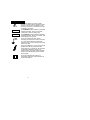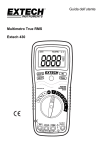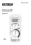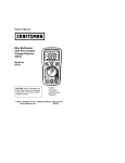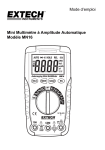
1
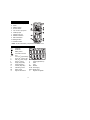
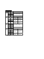
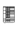
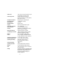
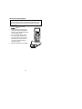
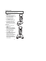
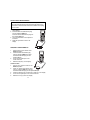
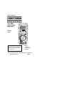
Owner's Manual
True RMS
Autoranging
Multimeter
Model No.
73754
CAUTION: Read, understand and
follow Safety Rules and Operating
Instructions in this manual before
using this product.
• Safety
• Operation
• Maintenance
• Español
© Sears, Roebuck and Co., Hoffman Estates, IL 60179 U.S.A.
www.craftsman.com
062606
TABLE OF CONTENTS
Warranty
Safety Instructions
Safety Symbols
Control and Jacks
Symbols and Annunciators
Specifications
Battery Installation
Operating Instructions
DC Voltage Measurements
AC Voltage Measurements
DC Current Measurements
AC Current Measurements
Resistance Measurements
Continuity Check
Diode Test
Capacitance Measurements
Frequency Measurements
% Duty Cycle Measurements
Temperature Measurements
Autoranging /Manual range selection
Relative Mode
Display Backlight
MAX
Hold
Auto Power Off
Low Battery Indication
Wrong Connection Indication
Maintenance
Battery Replacement
Fuse Replacement
Troubleshooting
Service and Parts
2
Page 3
4
5
6
6
7
10
11
11
12
13
14
15
16
16
17
17
17
18
19
19
20
20
20
20
20
20
21
22
23
24
24
ONE YEAR FULL WARRANTY
ONE YEAR FULL WARRANTY ON CRAFTSMAN
PROFESSIONAL MULTIMETER
If this CRAFTSMAN Professional Multimeter fails to give
complete satisfaction within one year from the date of purchase,
RETURN IT TO THE NEAREST SEARS STORE OR OTHER
CRAFTSMAN OUTLET IN THE UNITED STATES, and Sears
will replace it, free of charge.
This warranty gives you specific legal rights, and you may also
have other rights which vary from state to state.
Sears, Roebuck and Co., Dept. 817WA, Hoffman Estates, IL
60179
For Customer Assistance Call 9am - 5pm (ET)
Monday through Friday 1-888-326-1006
WARNING: USE EXTREME CAUTION IN THE USE OF THIS
DEVICE. Improper use of this device can result in injury or
death. Follow all safeguards suggested in this manual in addition
to the normal safety precautions used in working with electrical
circuits. DO NOT service this device if you are not qualified to do
so.
3
SAFETY INSTRUCTIONS
This meter has been designed for safe use, but must be operated
with caution. The rules listed below must be carefully followed for
safe operation.
1.
NEVER apply voltage or current to the meter that exceeds the
specified maximum:
Input Limits
Function
V DC or V AC
mA AC/DC
A AC/DC
Resistance, Diode Test,
Continuity
Maximum Input
600V DC/600V AC, 200Vrms on
400mV range
500mA 250V fast acting fuse
20A 250V fast acting fuse(30
seconds max every 15 minutes)
250Vrms for 15sec max
2.
USE EXTREME CAUTION when working with high voltages
3.
DO NOT measure voltage if the voltage on the "COM" input
jack exceeds 600V above earth ground
4.
DO NOT measure current of circuits whose voltage is greater
than 600V above earth ground
5.
NEVER connect the meter leads across a voltage source
while the function switch is in the resistance or diode mode.
Doing so can damage the meter
ALWAYS turn off the power and disconnect the test leads
before opening the cover to replace the fuse or battery
6.
7.
NEVER operate the meter unless the back cover is in place
and fastened securely
4
SAFETY SYMBOLS
This symbol adjacent to another symbol,
terminal or operating device indicates that the
operator must refer to an explanation in the
Operating Instructions to avoid personal injury
or damage to the meter.
WARNING
This WARNING symbol indicates a potentially
hazardous situation, which if not avoided,
could result in death or serious injury.
CAUTION
This CAUTION symbol indicates a potentially
hazardous situation, which if not avoided, may
result damage to the product.
MAX
600V
This symbol advises the user that the
terminal(s) so marked must not be connected
to a circuit point at which the voltage with
respect to earth ground exceeds (in this case)
600 VAC or VDC.
This symbol adjacent to one or more terminals
identifies them as being associated with
ranges that may, in normal use, be subjected
to particularly hazardous voltages. For
maximum safety, the meter and its test leads
should not be handled when these terminals
are energized.
This symbol indicates that a device is
protected throughout by double insulation or
reinforced insulation.
5
CONTROLS AND JACKS
1.
2.
3.
4.
5.
6.
7.
8.
9.
10.
11.
4000 count LCD display
HOLD
SELECT button
Function switch
mA, uA and A input jacks
COM input jack
Positive input jack
RANGE hold button
RELATIVE button
Backlight button
Protective holster
NOTE: Tilt stand and battery compartment are on rear of unit.
SYMBOLS AND ANNUNCIATORS
•)))
Continuity
Diode test
Battery status
n
m
k
M
Hz
%
AC
DC
ºF
Test lead connection
error
-9
nano (10 ) (capacitance)
-6
micro (10 ) (amps, cap)
-3
milli (10 ) (volts, amps)
3
kilo (10 ) (ohms)
6
mega (10 ) (ohms)
Hertz (frequency)
Percent (duty ratio)
Alternating current
Direct current
Degrees Fahrenheit
6
A
F
V
REL
AUTO
HOLD
ºC
Amps
Farads (capacitance)
Ohms
Volts
Relative
Autoranging
Display hold
Degrees Centigrade
SPECIFICATIONS
Function Range
DC
400mV
Voltage 4V
40V
400V
600V
AC
Voltage
DC
Current
AC
Current
Resolution
Accuracy
0.1mV
±(0.3% reading + 2 digits)
0.001V
0.01V
0.1V
1V
400mV
0.1mV
4V
40V
400V
600V
0.001V
0.01V
0.1V
1V
200µA
0.1µA
2000µA
1µA
20mA
200mA
2A
20A
0.01mA
0.1mA
0.001A
0.01A
400µA
0.1µA
4000µA
1µA
40mA
400mA
4A
20A
0.01mA
0.1mA
0.001A
0.01A
±(0.5% reading + 2 digits)
±(0.8% reading + 3 digits)
50 to 400Hz 400Hz to 1kHz
±(1.5% reading ±(2.5% reading
+ 15 digits)
+ 15digits)
±(1.5% reading ±(2.5% reading
+ 6 digits)
+ 8 digits)
±(1.8% reading ±(3% reading +
+ 6 digits)
8 digits)
±(1.5% reading + 3 digits)
±(2.5% reading + 5 digits)
50 to 400Hz
400Hz to 1KHz
±(1.8% reading ±(3.0% reading
+ 8 digits)
+ 7 digits)
±(3.0% reading ±(3.5% reading
+ 8 digits)
+ 10 digits)
o
o
o
o
NOTE: Accuracy is stated at 65 F to 83 F (18 C to 28 C) and less
than 75% RH.
7
Function
Resistance
Range
400
Resolution
Accuracy
0.1
±(0.8% reading + 4 digits)
4k
0.001k
40k
0.01k
400k
0.1k
4M
0.001M
40M
Duty Cycle
Temp
(type-K)
±(1.0% reading + 2 digits)
0.01M
±(3.0% reading + 5 digits)
0.01nF
±(5.0% reading + 7 digits)
400nF
0.1nF
±(3.0% reading + 5 digits)
4µF
0.001µF
40µF
0.01µF
100µF
0.1µF
Capacitance 40nF
Frequency
±(0.8% reading + 2 digits)
±(3.5% reading + 5 digits)
±(5.0% reading + 7 digits)
5.000Hz
0.001Hz
±(1.5% reading + 5 digits)
50.00Hz
0.01Hz
500.0Hz
0.1Hz
5.000kHz 0.001kHz
±(1.2% reading + 2 digits)
50.00kHz 0.01kHz
500.0kHz 0.1kHz
5.000MHz 0.001MHz
±(1.5% reading + 4 digits)
10.00MHz 0.01MHz
Sensitivity: 0.8V rms min. @ 20% to 80% duty cycle and
<100kHz; 5Vrms min @ 20% to 80% duty cycle and > 100kHz
0.1 to
0.1%
±(1.2% reading + 2 digits)
99.9%
Pulse width: 100s - 100ms, Frequency: 5Hz to 150kHz
-4 to 1382°F 1°F
±(3.0% reading + 3 digits)
-20 to
1°C
(probe accuracy not included)
750°C
NOTE: Accuracy specifications consist of two elements:
• (% reading) – This is the accuracy of the measurement circuit.
• (+ digits) – This is the accuracy of the analog to digital
converter.
8
Diode Test
Continuity Check
Temperature Sensor
Input Impedance
AC Response
ACV Bandwidth
Display
Overrange indication
Auto Power Off
Polarity
Measurement Rate
Low Battery Indication
Battery
Fuses
Operating Temperature
Storage Temperature
Operating Humidity
Storage Humidity
Operating Altitude
Weight
Size
Safety
Test current of 0.3mA maximum, open
circuit voltage 1.5V DC typical
Audible signal will sound if the
resistance is less than 150 (approx.),
test current <0.7mA
Requires type K thermocouple
>7.5M (VDC & VAC)
True rms
50Hz to 1kHz
4000 count backlit liquid crystal
“OL” is displayed
15 minutes (approximately)
Automatic (no indication for positive);
Minus (-) sign for negative.
2 times per second, nominal
“ ” is displayed if battery voltage
drops below operating voltage
one 9 volt (NEDA 1604) battery
mA, A ranges; 0.2A/250V fast blow
A range; 20A/250V ceramic fast blow
41ºF to 104ºF (5ºC to 40ºC)
o
o
o
o
-4 F to 140 F (-20 C to 60 C)
Max 80% up to 87ºF (31ºC)
decreasing linearly to 50% at
104ºF(40ºC)
<80%
7000ft. (2000) meters maximum.
0.753lb (342g) (includes holster).
7.36” x 3.2” x 2.0” (187 x 81 x 50mm)
(includes holster)
For indoor use and in accordance with
the requirements for double insulation
to IEC1010-1 (1995): EN61010-1
(1995) Overvoltage Category III,
Pollution Degree 2.
9
BATTERY INSTALLATION
WARNING: To avoid electric shock, disconnect the test leads
from any source of voltage before removing the battery cover.
1. Disconnect the test leads from the meter.
2. Remove the rear battery cover by removing the two screws
using a Phillips head screwdriver.
3. Insert the battery into battery clips, observing the correct
polarity.
4. Put the battery cover back in place and secure with the two
screws.
WARNING: To avoid electric shock, do not operate the meter
until the battery cover is in place and fastened securely.
NOTE: If your meter does not work properly, check the fuses and
batteries to make sure that they are still good and that they
are properly inserted.
10
OPERATING INSTRUCTIONS
WARNING: Risk of electrocution. High-voltage circuits, both AC
and DC, are very dangerous and should be measured with great
care.
1. ALWAYS turn the function switch to the OFF position when the
meter is not in use.
2. If “OL” appears in the display during a measurement, the value
exceeds the range you have selected. Change to a higher range.
NOTE: On some low AC and DC voltage ranges, with the test
leads not connected to a device, the display may show a
random, changing reading. This is normal and is caused by
the high-input sensitivity. The reading will stabilize and give
a proper measurement when connected to a circuit.
DC VOLTAGE MEASUREMENTS
CAUTION: Do not measure DC voltages if a motor on the
circuit is being switched ON or OFF. Large voltage surges may
occur that can damage the meter.
1. Set the function switch to the V
position.
2. Press the SELECT button to indicate
“DC” on the display.
3. Insert the black test lead banana
plug into the negative (COM) jack.
Insert the red test lead banana plug
into the positive (V) jack.
4. Touch the black test probe tip to the
negative side of the circuit.
Touch the red test probe tip to the
positive side of the circuit.
5. Read the voltage in the display.
11
AC VOLTAGE MEASUREMENTS
AC VOLTAGE: The probe tips may not be long enough to
contact the live parts inside some 240V outlets for appliances
because the contacts are recessed deep in the outlets. As a
result, the reading may show 0 volts when the outlet actually
has voltage on it.
WARNING: To avoid electric shock, make sure the probe tips
are touching the metal contacts inside the outlet before
assuming no voltage is present
CAUTION: Do not measure AC voltages if a motor on the
circuit is being switched ON or OFF. Large voltage surges may
occur that can damage the meter.
1. Set the function switch to the V
position.
2. Press the SELECT button to indicate
“AC” on the display.
3. Insert the black test lead banana
plug into the negative (COM) jack.
Insert red test lead banana plug into
the positive (V) jack.
4. Touch the black test probe tip to the
negative side of the circuit.
Touch the red test probe tip to the
positive side of the circuit.
5. Read the voltage in the display.
12
DC CURRENT MEASUREMENTS
CAUTION: Do not make current measurements on the 20A
scale for longer than 30 seconds. Exceeding 30 seconds may
cause damage to the meter and/or the test leads.
1. Insert the black test lead
banana plug into the negative
(COM) jack.
2. For current measurements up
to 4000A DC, set the
function switch to the A
position and insert the red test
lead banana plug into the
(A/mA) jack.
3. For current measurements up
to 400mA DC, set the function
switch to the mA position and
insert the red test lead
banana plug into the (A/mA)
jack.
4. For current measurements up
to 20A DC, set the function
switch to the A range and
insert the red test lead
banana plug into the 20A jack.
5. Press the SELECT button to
indicate “DC” on the display.
6. Remove power from the circuit under test,
then open up the circuit at the point where
you wish to measure current.
7. Touch the black test probe tip to the negative side of the circuit.
Touch the red test probe tip to the positive side of the circuit.
8. Apply power to the circuit.
9. Read the current in the display.
13
AC CURRENT MEASUREMENTS
WARNING: To avoid electric shock, do not attempt to
measure AC A in circuits that have voltages which exceed
250V AC.
CAUTION: Do not make current measurements on the 20A
scale for longer than 30 seconds. Exceeding 30 seconds may
cause damage to the meter and/or the test leads.
1. Insert the black test lead
banana plug into the negative
COM jack.
2. For current measurements up
to 4000A AC, set the
function switch to the A
position and insert the red
test lead banana plug into the
A/mA jack
3. For current measurements up
to 400mA AC, set the function
switch to the mA position and
insert the red test lead
banana plug into the A/mA
jack.
4. For current measurements up
to 20A AC, set the function
switch to the A range and
insert the red test lead
banana plug into the 20A jack.
5. Press the SELECT button to indicate “AC” on the display.
6. Remove power from the circuit under test, then open up the
circuit at the point where you wish to measure current.
7. Touch the black test probe tip to the negative side of the circuit.
Touch the red test probe tip to the positive side of the circuit.
8. Apply power to the circuit.
9. Read the current in the display.
14
RESISTANCE MEASUREMENTS
WARNING: To avoid electric shock, disconnect power to the
unit under test and discharge all capacitors before taking any
resistance measurements. Remove the batteries and unplug
the line cords.
1. Set the function switch to the
position.
2. Insert the black test lead banana
plug into the negative (COM) jack
Insert the red test lead banana plug
into the positive jack.
3. Touch the test probe tips across
the circuit or part under test. It is
best to disconnect one side of the
part under test so the rest of the
circuit will not interfere with the
resistance reading.
4. Read the resistance in the display.
15
CONTINUITY CHECK
WARNING: To avoid electric shock, never measure continuity
on circuits or wires that have voltage on them.
1. Set the function switch to the
position.
2. Insert the black lead banana plug
into the negative (COM) jack
Insert the red test lead banana plug
into the positive () jack.
3. Press the SELECT button to
indicate on the display
4. Touch the test probe tips to the
circuit or wire you wish to check.
5. If the resistance is less than
approximately 150, the audible
signal will sound. If the circuit is
open, the display will indicate “OL”.
DIODE TEST
1. Set the function switch to the
position
2. Insert the black test lead banana
plug into the negative COM jack
and the red test lead banana plug
into the positive diode jack.
3. Press the SELECT button to
indicate
on the display.
4. Touch the test probes to the diode
under test. Forward voltage will
typically indicate 0.400 to
0.700mV. Reverse voltage will
indicate “OL”. Shorted devices will
indicate near 0mV. Shorted
devices will indicate near 0mV and
an open device will indicate “OL”
in both polarities.
16
CAPACITANCE MEASUREMENTS
WARNING: To avoid electric shock, disconnect power to the
unit under test and discharge all capacitors before taking any
capacitance measurements. Remove the batteries and unplug
the line cords.
1. Set the rotary function switch to the
CAP position.
2. Insert the black test lead banana plug
into the negative COM jack.
Insert the red test lead banana plug into
the positive CAP jack.
3. Touch the test leads to the capacitor to
be tested.
4. Read the capacitance value in the
display
FREQUENCY MEASUREMENTS
1.
2.
3.
4.
Set the rotary function switch to the
FREQ % position.
Insert the black lead banana plug
into the negative COM jack and the
red test lead banana plug into the
positive Hz jack.
Touch the test probe tips to the
circuit under test.
Read the frequency on the display.
% DUTY CYCLE
1. Set the rotary function switch to the
FREQ % position.
2. Insert the black lead banana plug
into the negative COM jack and the
red test lead banana plug into the positive Hz jack.
3. Press the SELECT key momentarily to select % in the display.
4. Touch the test probe tips to the circuit under test.
5. Read the % duty cycle on the display.
17
TEMPERATURE MEASUREMENTS
1. Set the function switch to the Type K ºF or ºC position.
2. Insert the Temperature Probe into the input jacks, making sure
to observe the correct polarity.
3. Touch the Temperature Probe head to the part whose
temperature you wish to measure. Keep the probe touching the
part under test until the reading stabilizes (about 30 seconds).
4. Read the temperature in the display.
Note: The temperature probe is fitted with a type K mini connector.
A mini connector to banana connector adaptor is supplied
for connection to the input banana jacks.
18
AUTORANGING/MANUAL RANGE SELECTION
When the meter is first turned on, it automatically goes into
AutoRanging. This automatically selects the best range for the
measurements being made and is generally the best mode for
most measurements. For measurement situations requiring that
a range be manually selected, perform the following:
1.
Press the RANGE key. The AUTO display indicator will turn
off.
2. Press the RANGE key to step through the available ranges
until you select the range you want.
3. To exit the Manual Ranging mode and return to AutoRanging,
press and hold the RANGE key for 2 seconds.
Note: Manual ranging does not apply for the Capacitance,
Frequency and Temperature functions.
RELATIVE MODE
The relative measurement feature allows you to make
measurements relative to a stored reference value. A reference
voltage, current, etc. can be stored and measurements made in
comparison to that value. The displayed value is the difference
between the reference value and the measured value.
1.
Perform the measurement as described in the operating
instructions.
2. Press the REL button to store the reading in the display and
the "REL" indicator will appear on the display.
3. The display will now indicate the difference between the
stored value and the measured value.
4. Press the REL button to exit the relative mode.
Note: The Relative function does not operate in the Frequency
function.
19
DISPLAY BACKLIGHT
Press and hold the
button for >1 second to turn on or off the
display backlight function. The backlight will automatically turn
off after 30 seconds.
HOLD
The hold function freezes the reading in the display. Press the
HOLD key momentarily to activate or to exit the hold function.
AUTO POWER OFF
The auto off feature will turn the meter off after 15 minutes.
LOW BATTERY INDICATION
The
icon will appear in the lower left corner of the display
when the battery voltage becomes low. Replace the battery
when this appears.
WRONG CONNECTION INDICATION
The
icon will appear in the upper right corner of the display
and the buzzer will sound whenever the positive test lead is
inserted into the 20A or uA/mA input jack and a non-current
function is selected. If this occurs, turn the meter off and reinsert
the test lead into the proper input jack for the function selected.
20
MAINTENANCE
WARNING: To avoid electric shock, disconnect the test leads
from any source of voltage before removing the back cover or
the battery cover.
WARNING: To avoid electric shock, do not operate your meter
until the battery cover is in place and fastened securely.
This multimeter is designed to provide years of dependable service,
if the following care instructions are performed:
1. KEEP THE METER DRY. If it gets wet, wipe it off.
2. USE AND STORE THE METER IN NORMAL
TEMPERATURES. Temperature extremes can shorten the life
of the electronic parts and distort or melt plastic parts.
3. HANDLE THE METER GENTLY AND CAREFULLY. Dropping
it can damage the electronic parts or the case.
4. KEEP THE METER CLEAN. Wipe the case occasionally with a
damp cloth. DO NOT use chemicals, cleaning solvents, or
detergents.
5. USE ONLY FRESH BATTERIES OF THE RECOMMENDED
SIZE AND TYPE. Remove old or weak batteries so they do not
leak and damage the unit.
6. IF THE METER IS TO BE STORED FOR A LONG PERIOD
OF TIME, the batteries should be removed to prevent damage
to the unit.
UL LISTED
The UL mark does not indicate that this product has been
evaluated for the accuracy of its readings.
21
BATTERY REPLACEMENT
WARNING: To avoid electric shock, disconnect the test leads
from any source of voltage before removing the battery cover.
1. When the battery becomes exhausted or drops below the
operating voltage, “ ” will appear in the left-hand side of the
LCD display. The battery should be replaced.
2. Follow instructions for installing batteries. See the Battery
Installation section of this manual.
3. Dispose of the old batteries properly.
WARNING: To avoid electric shock, do not operate your meter
until the battery cover is in place and fastened securely.
NOTE: If your meter does not work properly, check the fuses and
batteries to make sure that they are still good and that they
are properly inserted.
22
FUSE REPLACEMENT
WARNING: To avoid electric shock, disconnect the test leads
from any source of voltage before removing the battery cover.
1.
2.
3.
4.
5.
6.
7.
8.
9.
10.
11.
Disconnect the test leads from the meter.
Remove the protective rubber holster.
Remove the battery cover (two “B” screws).
Disconnect and remove the battery.
Remove the four “A” screws securing the rear cover.
Remove the rear cover.
Lift the center circuit board straight up from the connectors to
gain access to the fuse holders.
Gently remove the old fuse and install the new fuse into the
holder.
Always use a fuse of the proper size and value (0.2A/250V fast
blow for the 200mA range, 20A/250V fast blow for the 20A
range).
Align the center board with the connectors and gently press
into place.
Replace and secure the rear cover, battery, battery cover and
screws.
WARNING: To avoid electric shock, do not operate your meter
until the battery cover is in place and fastened securely.
23
TROUBLESHOOTING
There may be times when your meter does not operate properly.
Here are some common problems that you may have and some
easy solutions to them.
Meter Does Not Operate:
1. Always read all the instructions in this manual before use.
2. Check to be sure the battery is properly installed.
3. Check to be sure the battery is good.
4. If the battery is good and the meter still doesn’t operate, check
to be sure that both ends of the fuse are properly installed.
If You Do Not Understand How the Meter Works:
1. Purchase “Multitesters and Their Use for Electrical Testing”,
(Item No. 82303).
2. Call our Customer Service Line 1-888-326-1006.
SERVICE AND PARTS
Item Number
Description
82376
93894
82398
73754-D
73754-C
73754-CS
82377
Fuse kit
9V battery
Set of black and red Test Leads
Replacement battery cover
Front Cover
Rear cover screws
Thermocouple probe
For replacement parts shipped directly to your home
Call 9 am – 5 pm Eastern Time, M - F
1-888-326-1006
24