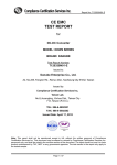
1
Report No: 91002404-D
FCC DoC
TEST REPORT
for
DC-DC CONVERTER
Model: MU / MAU SERIES
Brand: DANUBE
Test Report Number:
91002404-D
Issued for
Danube Enterprise Co., Ltd.
A2, No. 255, Fengren Rd., Renwu Shiang, Kaohsiung County 814, Taiwan(R.O.C.)
Issued by
Compliance Certification Services Inc.
Tainan Laboratory
No. 8, Jiu Cheng Ling, Jiaokeng Village, Sinhua
Township, Tainan Hsien 712, Taiwan R.O.C.
TEL: 886-6-580-2201
FAX: 886-6-580-2202
Issued Date: October 28, 2009
Note: This report shall not be reproduced except in full, without the written approval of Compliance
Certification Services Inc. This document may be altered or revised by Compliance Certification
Services Inc. personnel only, and shall be noted in the revision section of the document. The client
should not use it to claim product endorsement by TAF, NIST or any government agencies. The test
results in the report only apply to the tested sample.
Page 1 / 28
Report No: 91002404-D
REVISION HISTORY
Rev.
Issue
Date
Revisions
Effect Page
Revised By
00
October 28, 2009
Initial Issue
ALL
Leah Peng
Page 2
This report shall not be reproduced except in full, without the written approval of Compliance Certification Services.
Report No: 91002404-D
TABLE OF CONTENTS
1
TEST RESULT CERTIFICATION......................................................................................... 4
2
EUT DESCRIPTION................................................................................................................. 5
3
TEST METHODOLOGY ......................................................................................................... 7
3.1. DECISION OF FINAL TEST MODE................................................................................... 7
3.2. EUT SYSTEM OPERATION ............................................................................................... 7
4
SETUP OF EQUIPMENT UNDER TEST .............................................................................. 8
4.1. DESCRIPTION OF SUPPORT UNITS ................................................................................ 8
4.2. CONFIGURATION OF SYSTEM UNDER TEST............................................................... 8
5
FACILITIES AND ACCREDITATIONS ............................................................................... 9
5.1. FACILITIES .......................................................................................................................... 9
5.2. ACCREDITATIONS ............................................................................................................. 9
5.3. MEASUREMENT UNCERTAINTY.................................................................................... 9
6
EMISSION TEST .................................................................................................................... 10
6.1. CONDUCTED EMISSION MEASUREMENT.................................................................. 10
6.2. LIMITS OF RADIATED EMISSION MEASUREMENT ................................................. 13
7
PHOTOGRAPHS OF THE TEST CONFIGURATION ..................................................... 28
Page 3
This report shall not be reproduced except in full, without the written approval of Compliance Certification Services.
Report No: 91002404-D
2. EUT DESCRIPTION
Product
DC-DC CONVERTER
Model
MU / MAU SERIES
Brand Name
DANUBE
Applicant
Danube Enterprise Co., Ltd.
Manufacturer
Danube Enterprise Co., Ltd.
Housing material
Metal
EUT Type
Engineering Sample.
Serial Number
N/A
Received Date
October 2, 2009
Product Sample.
Mass Product Sample.
For model: MAUD-0505LK (I/P:5VDC, O/P:±5VDC, ±100mA)
For model: MAUD-4805LK(I/P:48VDC, O/P:±5VDC, ±100mA)
Power Source
For model: MUS-0505LK
(I/P: 5VDC, O/P:5VDC,
200mA)
For model: MUS-4805LK
(I/P: 48VDC, O/P:5VDC, 200mA)
For model: MUS-2405LK (I/P: 24VDC, O/P:5VDC, 200mA)
For model: MAUS-2415LK (I/P: 24VDC,O/P:15VDC, 67mA)
NOTE: Client consigns six model samples to test (Model Number: MAUD-0505LK; MAUD-4805LK;
MUS-0505LK; MUS-4805LK; MUS-2405LK; MAUS-2415LK). Therefore, the testing Lab. just
guarantees the unit, which has been tested.
Page 5
This report shall not be reproduced except in full, without the written approval of Compliance Certification Services.
Report No: 91002404-D
MU PARTNUMBES STRUCTURE
Model Name
Difference
MUS-x1x2(F)L(K)
M= Series Name
MUS-x1x2(F)L(K)-zzz
U= Unregulated
S= Single output voltage
x1= input voltage(05;12;15;24;48)
x2= Output voltage(05;09;12;15;24)
F= Fuse (Optional,
if Suffix” F”)
L= Operating Temperature=-40 °C to +85 °C
K= Isolation Voltage 3KVDC (Optional,
if Suffix” K”)
zzz= 0~9,A~Z or blank for market purpose,
MAU PARTNUMBES STRUCTURE
Model Name
Difference
MAUv-x1x2(F)L(K)
MA=Series Name
MAUv-x1x2(F)L(K)-zzz
U=Unregulated
v=Type of output voltage (S=single output or D=Dual output)
x1=input voltage(05;12;15;24;48)
x2=Output voltage(05;09;12;15;24;+/-5;+/-9;+/-12;+/-15;+/-24)
F= Fuse (Optional,
if Suffix” F”)
L= Operating Temperature=-40 °C to +85 °C
K= Isolation Voltage 3KVDC (Optional,
if Suffix” K”)
zzz= 0~9,A~Z or blank for market purpose,
Page 6
This report shall not be reproduced except in full, without the written approval of Compliance Certification Services.
Report No: 91002404-D
3.
TEST METHODOLOGY
3.1 DECISION OF FINAL TEST MODE
The EUT was tested together with the above additional components, and a configuration,
which produced the worst emission levels, was selected and recorded in this report.
The test configuration/ mode is as the following:
Test Mode
1. Full Load
Model Number:
(1) MAUD-0505LK
(2) MAUD-4805LK
(3) MUS-0505LK
(4) MUS-4805LK
(5) MUS-2405LK
(6) MAUS-2415LK
3.2 EUT SYSTEM OPERATION
1.
2.
3.
Setup whole system for test as shown on setup diagram.
Turn on power and check function.
Start to test.
Page 7
This report shall not be reproduced except in full, without the written approval of Compliance Certification Services.
Report No: 91002404-D
4.
SETUP OF EQUIPMENT UNDER TEST
4.1 DESCRIPTION OF SUPPORT UNITS
The EUT has been tested as an independent unit together with other necessary accessories or
support units. The following support units or accessories were used to form a representative test
configuration during the tests.
No.
Product
Manufacturer
Model No.
Certify No.
Signal cable
1
DC power supply
GW
GPC-6030P
DOC
Power cable, unshd, 1.6m
No.
A
Signal cable description
DC Input cable
Shielded, 0.8m, 1pcs.
NOTE:
1) All the equipment/cables were placed in the worst-case configuration to maximize the emission during
the test.
2) Grounding was established in accordance with the manufacturer’s requirements and conditions for the
intended use.
4.2 CONFIGURATION OF SYSTEM UNDER TEST
Load
EUT
A
DC power
supply
AC
Source
Page 8
This report shall not be reproduced except in full, without the written approval of Compliance Certification Services.
Report No: 91002404-D
5.
FACILITIES AND ACCREDITATIONS
5.1 FACILITIES
All measurement facilities used to collect the measurement data are located at
No. 8, Jiu Cheng Ling, Jiaokeng Village,Sinhua Township, Tainan Hsien 712, Taiwan R.O.C.
The sites are constructed in conformance with the requirements of ANSI C63.4 and CISPR
Publication 22. All receiving equipment conforms to CISPR Publication 16-1, “Radio Interference
Measuring Apparatus and Measurement Methods.”
1.1. ACCREDITATIONS
Our laboratories are accredited and approved by the following approval agencies according to
ISO/IEC 17025.
USA
FCC
Japan
VCCI
Canada
INDUSTRY CANADA
Taiwan
TAF, BSMI
Europe
TÜV NORD
Copies of granted accreditation certificates are available for downloading from our web site,
http://www.ccsemc.com.tw
5.2 MEASUREMENT UNCERTAINTY
Where relevant, the following measurement uncertainty levels have been estimated for tests
performed on the EUT as specified in CISPR 16-4-2:
Measurement
Frequency
Uncertainty
Conducted emissions
9kHz~30MHz
±2.05dB
Radiated emissions
30MHz ~ 1000MHz
±2.39dB
This uncertainty represents an expanded uncertainty expressed at approximately the 95%
confidence level using a coverage factor of k=2.
Page 9
This report shall not be reproduced except in full, without the written approval of Compliance Certification Services.
Report No: 91002404-D
6.
EMISSION TEST
6.1 CONDUCTED EMISSION MEASUREMENT
6.1.1 LIMITS
Class A (dBuV)
FREQUENCY (MHz)
Class B (dBuV)
Quasi-peak
Average
Quasi-peak
Average
0.15 - 0.5
79
66
66 - 56
56 - 46
0.50 - 5.0
73
60
56
46
5.0 - 30.0
73
60
60
50
NOTE:
(1) The lower limit shall apply at the transition frequencies.
(2) The limit decreases in line with the logarithm of the frequency in the range of 0.15 to 0.50 MHz.
(3) All emanations from a class A/B digital device or system, including any network of conductors and
apparatus connected thereto, shall not exceed the level of field strengths specified above.
6.1.2 TEST INSTRUMENTS
Conducted Emission room #1
Name of Equipment
Manufacturer
SCHWARZBECK
L.I.S.N.
Model
Serial Number
NNLK
8121-446
8121
Calibration Due
NOV. 19, 2009
For Insertion loss
Rohde & Schwarz
ESH 3-Z5
840062/021
OCT. 05, 2010
TEST RECEIVER
Rohde & Schwarz
ESCS 30
100348
JUL. 02, 2010
BNC COAXIAL
CABLE
CCS
BNC50
11
JAN. 14, 2010
e-3 (5.04211c)
Test S/W
R&S (2.27)
NOTE: The calibration interval of the above test instruments is 12 months and the calibrations are
traceable to NML/ROC and NIST/USA.
Page 10
This report shall not be reproduced except in full, without the written approval of Compliance Certification Services.
Report No: 91002404-D
6.1.3 TEST PROCEDURES
Procedure of Preliminary Test
z
The EUT and Support equipment, if needed, was set up as per the test configuration to simulate
typical usage per the user’s manual. When the EUT is a tabletop system, a wooden table with a
height of 0.8 m is used and is placed on the ground plane as per ANSI C63.4 (see Test Facility for
the dimensions of the ground plane used). When the EUT is a floor standing equipment, it is
placed on the ground plane, which has a 3-12 mm non-conductive covering to insulate the EUT
from the ground plane.
z
All I/O cables were positioned to simulate typical actual usage as per ANSI C63.4.
z
The test equipment EUT installed received DC main power, through a Line Impedance
Stabilization Network (LISN), which supplied power source and was grounded to the ground
plane.
z
All support equipment power received from a second LISN.
z
The EUT test program was started. Emissions were measured on each current carrying line of the
EUT using an EMI Test Receiver connected to the LISN powering the EUT.
z
The Receiver scanned from 150kHz to 30MHz for emissions in each of the test modes.
z
During the above scans, the emissions were maximized by cable manipulation.
z
The test mode(s) described in Item 3.1 were scanned during the preliminary test.
z
After the preliminary scan, we found the test mode described in Item 3.1 producing the highest
emission level.
z
The EUT configuration and cable configuration of the above highest emission levels were
recorded for reference of the final test.
Procedure of Final Test
z
EUT and support equipment were set up on the test bench as per the configuration with highest
emission level in the preliminary test.
z
A scan was taken on both power lines, Line 1 and Line 2, recording at least the six highest
emissions. Emission frequency and amplitude were recorded into a computer in which correction
factors were used to calculate the emission level and compare reading to the applicable limit.
z
The test data of the worst-case condition(s) was recorded.
Page 11
This report shall not be reproduced except in full, without the written approval of Compliance Certification Services.
Report No: 91002404-D
6.1.4 TEST SETUP
Vert. reference plane
EMI receiver
40cm
EUT
80cm
LISN
z
Reference ground plane
For the actual test configuration, please refer to the related item – Photographs of the Test
Configuration.
6.1.5 DATA SAMPLE
Freq.
(MHz)
LISN
Factor
(dB)
Cable
Loss
(dB)
Meter
Reading
(dBuV)
x.xx
9.6
0.1
15.7
Measured
Limits
Level
(dBuV)
(dBuV)
25.4
46
Over
Limits
(dBuV)
Detector
-20.6
QP
REMARKS: 1. Level (dBuV) = Read Level (dBuV) + LISN Factor (dB) + Cable Loss (dB)
2. Over Limit value (dB) = Level (dBuV) – Limit Line (dBuV)
6.1.6 TEST RESULTS
NOTE: This EUT has not connection to AC Source directly. No applicability for this test.
Page 12
This report shall not be reproduced except in full, without the written approval of Compliance Certification Services.
Report No: 91002404-D
6.2 LIMITS OF RADIATED EMISSION MEASUREMENT
dBuV/m (At 10m)
FREQUENCY (MHz)
Class A
Class B
30 ~ 230
40
30
230 ~ 1000
47
37
NOTE: (1) The lower limit shall apply at the transition frequencies.
(2) Emission level (dBuV/m) = 20 log Emission level (uV/m).
6.2.1 TEST INSTRUMENTS
Open Area Test Site # 5
Name of Equipment
Manufacturer
Model
Serial Number
Calibration Due
TEST RECEIVER
Rohde & Schwarz
ESCS 30
100294
FEB. 05, 2010
TYPE N COAXIAL
CABLE
SUHNER
CHA9513
5
AUG. 26, 2010
BILOG ANTENNA
Sunol sciences
JB1
A070506-1
SEP. 16, 2010
Test Software
EMI e-3 / AUDIX (5.04211c)
NOTE: 1. The calibration interval of the above test instruments is 12 months and the calibrations are
traceable to NML/ROC and NIST/USA.
2. N.C.R = No Calibration Request.
Page 13
This report shall not be reproduced except in full, without the written approval of Compliance Certification Services.
Report No: 91002404-D
6.2.2 TEST PROCEDURES
Procedure of Preliminary Test
z
The equipment was set up as per the test configuration to simulate typical usage per the user’s
manual. When the EUT is a tabletop system, a wooden turntable with a height of 0.8 meters is
used which is placed on the ground plane. When the EUT is a floor standing equipment, it is
placed on the ground plane which has a 3-12 mm non-conductive covering to insulate the EUT
from the ground plane.
z
Support equipment, if needed, was placed as per ANSI C63.4.
z
All I/O cables were positioned to simulate typical usage as per ANSI C63.4.
z
The EUT received DC power source from the outlet socket under the turntable. All support
equipment power received from another socket under the turntable.
z
Mains cables, telephone lines or other connections to auxiliary equipment located outside the test
shall drape to the floor. No extension cords shall be used to mains receptacle.
z
The antenna was placed at 10 m away from the EUT as stated in ANSI C63.4. The antenna
connected to the Spectrum Analyzer via a cable and at times a pre-amplifier would be used.
z
The Analyzer / Receiver quickly scanned from 30MHz to 1000MHz. The EUT test program was
started. Emissions were scanned and measured rotating the EUT to 360 degrees and positioning
the antenna 1 to 4 m above the ground plane, in both the vertical and the horizontal polarization,
to maximize the emission reading level.
z
The test mode(s) described in Item 3.1 were scanned during the preliminary test:
z
After the preliminary scan, we found the test mode described in Item 3.1 producing the highest
emission level.
z
The EUT and cable configuration, antenna position, polarization and turntable position of the
above highest emission level were recorded for the final test.
Procedure of Final Test
z
EUT and support equipment were set up on the turntable as per the configuration with highest
emission level in the preliminary test.
z
The Analyzer / Receiver scanned from 30MHz to 1000MHz. Emissions were scanned and
measured rotating the EUT to 360 degrees, varying cable placement and positioning the antenna 1
to 4 m above the ground plane, in both the vertical and the horizontal polarization, to maximize
the emission reading level.
z
Recorded at least the six highest emissions. Emission frequency, amplitude, antenna position,
polarization and turntable position were recorded into a computer in which correction factors were
used to calculate the emission level and compare reading to the applicable limit and only Q.P.
reading is presented.
z
The test data of the worst-case condition(s) was recorded.
Page 14
This report shall not be reproduced except in full, without the written approval of Compliance Certification Services.
Report No: 91002404-D
6.2.3 TEST SETUP
Test table &
Turntable
1m ~ 4m
EUT
Coaxial
Cable
Power
Cable
0.8 m
10 m
z
Ground Plane
ToToPower
power source
Filter
Filter
EMI
Receiver
For the actual test configuration, please rfer to the related item – Photographs of the Test
Configuration.
6.2.4 DATA SAMPLE
Freq.
(MHz)
Reading
Level
(dBuV)
Antenna
Factor
(dB/m)
Cable
Loss
(dB)
Measure
Level
(dBuV/m)
xx.xx
14.00
12
0.2
26.2
Limit
Over
Limit
(dBuV/m) (dBuV/m)
30
-3.80
REMARKS: 1.Level (dBuV/m) = Read Level (dBuV) + Antenna Factor (dB/m) + Cable loss (dB)
2.Over Limit value (dB) = Level (dBuV/m)-Limit Line(dBuV/m)
Page 15
This report shall not be reproduced except in full, without the written approval of Compliance Certification Services.
Report No: 91002404-D
6.2.5 TEST RESULTS
Model No.
Environmental
Conditions
Antenna Pole
Detector Function
REMARKS:
MAUD-0505LK
Test Mode
Full Load
33.2℃, 50 % RH
Resolution
Bandwidth
120 kHz
Vertical
Antenna Distance
10m
Quasi-peak.
Tested by
Rock Guo
1.Level (dBuV/m) = Read Level (dBuV) + Antenna Factor (dB/m) + Cable loss (dB)
2.Over Limit value (dB) = Level (dBuV/m)-Limit Line(dBuV/m)
Page 16
This report shall not be reproduced except in full, without the written approval of Compliance Certification Services.
Report No: 91002404-D
Model No.
Environmental
Conditions
Antenna Pole
Detector Function
REMARKS:
MAUD-0505LK
Test Mode
Full Load
33.2℃, 50 % RH
Resolution
Bandwidth
120 kHz
Horizontal
Antenna Distance
10m
Quasi-peak.
Tested by
Rock Guo
1.Level (dBuV/m) = Read Level (dBuV) + Antenna Factor (dB/m) + Cable loss (dB)
2.Over Limit value (dB) = Level (dBuV/m)-Limit Line(dBuV/m)
Page 17
This report shall not be reproduced except in full, without the written approval of Compliance Certification Services.
Report No: 91002404-D
Model No.
Environmental
Conditions
Antenna Pole
Detector Function
REMARKS:
MAUD-4805LK
Test Mode
Full Load
33.2℃, 50 % RH
Resolution
Bandwidth
120 kHz
Vertical
Antenna Distance
10m
Quasi-peak.
Tested by
Rock Guo
1.Level (dBuV/m) = Read Level (dBuV) + Antenna Factor (dB/m) + Cable loss (dB)
2.Over Limit value (dB) = Level (dBuV/m)-Limit Line(dBuV/m)
Page 18
This report shall not be reproduced except in full, without the written approval of Compliance Certification Services.
Report No: 91002404-D
Model No.
Environmental
Conditions
Antenna Pole
Detector Function
REMARKS:
MAUD-4805LK
Test Mode
Full Load
33.2℃, 50 % RH
Resolution
Bandwidth
120 kHz
Horizontal
Antenna Distance
10m
Quasi-peak.
Tested by
Rock Guo
1.Level (dBuV/m) = Read Level (dBuV) + Antenna Factor (dB/m) + Cable loss (dB)
2.Over Limit value (dB) = Level (dBuV/m)-Limit Line(dBuV/m)
Page 19
This report shall not be reproduced except in full, without the written approval of Compliance Certification Services.
Report No: 91002404-D
Model No.
Environmental
Conditions
Antenna Pole
Detector Function
REMARKS:
MUS-0505LK
Test Mode
Full Load
33.2℃, 50 % RH
Resolution
Bandwidth
120 kHz
Vertical
Antenna Distance
10m
Quasi-peak.
Tested by
Rock Guo
1.Level (dBuV/m) = Read Level (dBuV) + Antenna Factor (dB/m) + Cable loss (dB)
2.Over Limit value (dB) = Level (dBuV/m)-Limit Line(dBuV/m)
Page 20
This report shall not be reproduced except in full, without the written approval of Compliance Certification Services.
Report No: 91002404-D
Model No.
Environmental
Conditions
Antenna Pole
Detector Function
REMARKS:
MUS-0505LK
Test Mode
Full Load
33.2℃, 50 % RH
Resolution
Bandwidth
120 kHz
Horizontal
Antenna Distance
10m
Quasi-peak.
Tested by
Rock Guo
1.Level (dBuV/m) = Read Level (dBuV) + Antenna Factor (dB/m) + Cable loss (dB)
2.Over Limit value (dB) = Level (dBuV/m)-Limit Line(dBuV/m)
Page 21
This report shall not be reproduced except in full, without the written approval of Compliance Certification Services.
Report No: 91002404-D
Model No.
Environmental
Conditions
Antenna Pole
Detector Function
REMARKS:
MUS-4805LK
Test Mode
Full Load
33.2℃, 50 % RH
Resolution
Bandwidth
120 kHz
Vertical
Antenna Distance
10m
Quasi-peak.
Tested by
Rock Guo
1.Level (dBuV/m) = Read Level (dBuV) + Antenna Factor (dB/m) + Cable loss (dB)
2.Over Limit value (dB) = Level (dBuV/m)-Limit Line(dBuV/m)
Page 22
This report shall not be reproduced except in full, without the written approval of Compliance Certification Services.
Report No: 91002404-D
Model No.
Environmental
Conditions
Antenna Pole
Detector Function
REMARKS:
MUS-4805LK
Test Mode
Full Load
33.2℃, 50 % RH
Resolution
Bandwidth
120 kHz
Horizontal
Antenna Distance
10m
Quasi-peak.
Tested by
Rock Guo
1.Level (dBuV/m) = Read Level (dBuV) + Antenna Factor (dB/m) + Cable loss (dB)
2.Over Limit value (dB) = Level (dBuV/m)-Limit Line(dBuV/m)
Page 23
This report shall not be reproduced except in full, without the written approval of Compliance Certification Services.
Report No: 91002404-D
Model No.
Environmental
Conditions
Antenna Pole
Detector Function
REMARKS:
MUS-2405LK
Test Mode
Full Load
33.2℃, 50 % RH
Resolution
Bandwidth
120 kHz
Vertical
Antenna Distance
10m
Quasi-peak.
Tested by
Rock Guo
1.Level (dBuV/m) = Read Level (dBuV) + Antenna Factor (dB/m) + Cable loss (dB)
2.Over Limit value (dB) = Level (dBuV/m)-Limit Line(dBuV/m)
Page 24
This report shall not be reproduced except in full, without the written approval of Compliance Certification Services.
Report No: 91002404-D
Model No.
Environmental
Conditions
Antenna Pole
Detector Function
REMARKS:
MUS-2405LK
Test Mode
Full Load
33.2℃, 50 % RH
Resolution
Bandwidth
120 kHz
Horizontal
Antenna Distance
10m
Quasi-peak.
Tested by
Rock Guo
1.Level (dBuV/m) = Read Level (dBuV) + Antenna Factor (dB/m) + Cable loss (dB)
2.Over Limit value (dB) = Level (dBuV/m)-Limit Line(dBuV/m)
Page 25
This report shall not be reproduced except in full, without the written approval of Compliance Certification Services.
Report No: 91002404-D
Model No.
Environmental
Conditions
Antenna Pole
Detector Function
REMARKS:
MAUS-2415LK
Test Mode
Full Load
33.2℃, 50 % RH
Resolution
Bandwidth
120 kHz
Vertical
Antenna Distance
10m
Quasi-peak.
Tested by
Rock Guo
1.Level (dBuV/m) = Read Level (dBuV) + Antenna Factor (dB/m) + Cable loss (dB)
2.Over Limit value (dB) = Level (dBuV/m)-Limit Line(dBuV/m)
Page 26
This report shall not be reproduced except in full, without the written approval of Compliance Certification Services.
Report No: 91002404-D
Model No.
Environmental
Conditions
Antenna Pole
Detector Function
REMARKS:
MAUS-2415LK
Test Mode
Full Load
33.2℃, 50 % RH
Resolution
Bandwidth
120 kHz
Horizontal
Antenna Distance
10m
Quasi-peak.
Tested by
Rock Guo
1.Level (dBuV/m) = Read Level (dBuV) + Antenna Factor (dB/m) + Cable loss (dB)
2.Over Limit value (dB) = Level (dBuV/m)-Limit Line(dBuV/m)
Page 27
This report shall not be reproduced except in full, without the written approval of Compliance Certification Services.
Report No: 91002404-D
7
PHOTOGRAPHS OF THE TEST CONFIGURATION
RADIATED EMISSION TEST
END OF REPORT
Page 28
This report shall not be reproduced except in full, without the written approval of Compliance Certification Services.