1
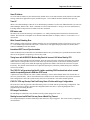
September 25, 2000 GFK-1490F IMPORTANT PRODUCT INFORMATION READ THIS INFORMATION FIRST Product: IC693CPU364 CPU Module with Ethernet Interface IC693CPU364-BF with CPU Firmware Release 10.50 Introduction This document contains information that is not available in any other publication; therefore, we recommend you save it for future reference. This document discusses the features of CPU module IC693CPU364 (CPU364). This module provides two functions in one module: (1) it serves as a High Performance CPU, and (2) it provides Ethernet communications capability with its built-in Ethernet Interface. This document also discusses firmware release 10.50, which corrects the problems listed in the section “Problems Resolved by this Release (10.50).” CPU364 Feature Highlights for Release 10.50 None CPU364 Feature Highlights for Previous Release 10.00 Note: Implementing the following CPU features requires the use of VersaPro 1.10 PLC software. These features are documented in theVersaPro 1.10 on-line help system. • Support was added for the IC693DSM314 servo module. • • • Added support for storing Local Logic Programs. These programs are stored to the CPU from the programmer. In turn, the CPU automatically stores them to the DSM314 module along with the module’s configuration settings. The limit on the size of all Local Logic Programs is 65280 bytes. Reboot after Fatal Fault – If activated, this feature enables the IC693 PLC system to automatically resume normal operation after a fatal fault has occurred. Following the fatal fault, the PLC will automatically reset and resume execution. If fatal faults are present following the power up, the PLC will still be allowed to transition to run mode. The user can enable this feature through a configuration parameter, and can identify the maximum number of retries and the time period these retries may occur within through new Service Request #48. New Service Request 49 may then be used to determine the number of fatal faults and retries that have occurred. Addition of the Drum Sequencer function block. This function block operates in the same manner as it does on the IC200 CPU. CPU364 Feature Highlights for Previous Release 9.10 Ethernet Global Data and Name Resolution support were added in this release. Version 2.2 or later of the Windows -based PLC programming software or version 1.0 or later of the VersaPro Windows-based programming software is required for configuration of these features. For details, refer to the software online help, the TCP/IP Ethernet Communications for the IC69* User's Manual, and the TCP/IP Ethernet Communications for the IC69* Station Manager's Manual. Windows is a registered trademark of Microsoft Corporation 2 Important Product Information GFK-1490F CPU364 Feature Highlights for Previous Release 9.00 • Software Floating-Point. The CPU364 supports all of the floating-point function blocks that are currently supported by the CPU352. They are implemented in firmware using floating point emulation in the CPU364. These Floating-Point math function blocks are described in the IC693 PLC Reference Manual. • User memory totals 240K bytes. %R, %AI, and %AQ references are configurable up to 16K of %R, 8K of %AI and 8K of %AQ memory using the MS-DOS PLC programming software, version 9.02 or later. These three references are configurable up to 32K in release 1.0 of the VersaPro software and release 2.2 of the Windows-based PLC programming software. Configuration instructions for this feature are described in the MS-DOS IC693 Programming Software User’s Manual, and are included in on-line help in both of the Windows PLC Programming Software packages. • Sequential Event Recorder. The Sequential Event Recorder can be used to record up to 1024 samples of 32 individual discrete (bit) references. This function block is described in the IC693 PLC Reference Manual and in online help in the Windows PLC Programming Software. • Break-free SNP. The SNP protocol no longer requires a break to operate. This allows SNP to work over a wider variety of modems. Ethernet Features • The CPU364 supports connection to an Ethernet network via either (but not both) of two built-in Ethernet network ports: AAUI: Capability is provided for connection to various types of Ethernet LANs via an external AAUI 1. transceiver connected to the AAUI port. The IC649AEA103 AAUI transceiver may be used, or the user may supply a different model that meets AAUI standards. 10Base T: The CPU364 provides direct connection to a 10BaseT (twisted pair) Ethernet LAN from its 2. 10BaseT port. • The CPU364 provides network communications using SRTP (Service Request Transfer Protocol) over standard TCP/IP (Transmission Control Protocol / Internet Protocol) on an Ethernet Local Area Network (LAN). The CPU364 supports communications with other IC693 PLCs and/or IC697 PLCs equipped with TCP/IP Ethernet Interfaces, and with MS-DOS TCP/IP programming software and applications which use the TCP/IP Host Communications Toolkit (HCT) Software. Hardware Identification The following table shows the revision level of the circuit boards used in this version (BF) of the IC693CPU364. If you wish to upgrade an existing CPU364 to firmware version 10.50, you may purchase the kit identified in the following table. All previous versions are capable of being upgraded. CPU Model (Version) Circuit Board ID IC693CPU364-BF Circuit Board Version CX3A1 (CPU) 44A739579-G01R05 or later EE3A1 (Ethernet) 44A739599-G01R04 or later Firmware Upgrade Kit Catalog Number 44A747767-G04 Firmware Identification CPU Catalog Number IC693CPU364-BF CPU Firmware Main: 10.50 (35A1) Boot: 9.00 (33A1) Revision Daughterboard Firmware Main: 1.10 (25A1) Boot: 1.00 (33A1) Important Product Information 3 GFK-1490F Functional Compatibility • The Windows PLC Programming Software version 2.00 or later must be used to take advantage of C programming or Sequential Function Chart (SFC) subroutines. • Version 4.00 or later of the C toolkit must be used for C programming. • The MS-DOS PLC Programming Software Version 9.02 or later must be used to take advantage of the new features introduced in firmware release 9.00. These new features are listed in the section “New Features and Functionality of Firmware Release 9.00.” • The Windows PLC Programming Software version 2.20 or later or VersaPro version 1.00 or later is required for configuration of the Ethernet Global Data and configurable Name Resolution features of the 364 PLC. • VersaPro version 1.10 or later is required to use the new features of release 10.00 and to configure and program the IC693DSM314 servo module. Operating Notes CPU364 Hardware Update (Version BD) to Enhance EMC Performance A hardware update (from version AD to version BD) was made to the CPU364 to enhance its EMC performance. The update will also allow faster backplane I/O data transfers to be implemented in the future while still meeting all EMC requirements. This update is fully compatible with all existing products. To realize the maximum EMC benefit, this version of the CPU must be used with the latest 90-30 baseplates. Radiated emissions (EN 55011) of the 90-30 system are reduced with this update. User Flash Contents User information, consisting of program, configuration, CPU ID (used for SNP communications), and status tables in RAM memory, will automatically be cleared if the CPU firmware in flash memory is changed. You will need to restore these if upgrading firmware. A recommended procedure is to first back up your user information from RAM memory to Flash memory. Then write your new firmware to Flash memory (firmware is stored in a different location in Flash memory than that used for storing user information such as program, configuration, etc.). Finally, write your user information back out of Flash into RAM memory. As an alternative, your user information (program, configuration, etc.) can be restored from a computer-based backup program folder using your PLC programming software. The SNP ID must be set separately, using the programming software or the Hand-Held Programmer (HHP). Firmware Upgrade Information The Model 364 CPU operating firmware is stored in flash memory. The CPU and embedded Ethernet Interface each have their own separate firmware. Firmware upgrades are provided on diskette and must be serially downloaded from a Personal Computer. An IBM AT personal computer or better PC with a minimum 640K of RAM, one 3.5” diskette drive, MS-DOS version 3.3 or later (or Windows 95 or later), and one RS-232 serial port is required. In addition, two serial cables are required: • CPU Firmware: IC690ACC901 Mini Converter Kit with cable (RS-232/RS-485). • Ethernet Interface Firmware: IC693CBL316 “Station Manager’s Cable.” IC693CMM321 Ethernet Option Module Version Requirements All IC693 Ethernet Interface (IC693CMM321) modules used with this CPU should be updated to IC693CMM321 firmware release 1.10 or later. This is also a requirement of the TCP/IP Ethernet version of the MS-DOS programming software. FBC Compatibility FBC version 3 or later is required for this CPU. 4 Important Product Information GFK-1490F Writing Flash Using a Serial Programmer When writing very large programs to flash memory, it may be necessary to increase the Windows programming software request timeout value to avoid receiving a request timeout message. An upper bound of 25 seconds is typically satisfactory. For further details, see the item “Store of Program or Reference Tables to Flash may Cause Loss of Ethernet Communications” later in this section. Storing Large Configurations The IC693 PLCwill normally support 20 DSM314 modules in a system. This number may be reduced by other modules in the system, such as APM and GBC modules. It may also be further reduced by having datagrams set up which will read the reference or fault tables. If the configuration and user program is stored at the same time, the presence of either C blocks within the LD program, or a C logic program may also affect the number of DSM314 modules which may be included in a system. If the store fails, it may be possible to store the configuration to the system by first storing the logic program, and then storing the configuration on a separate store request. The number of modules supported may be further reduced by the memory available to the user. Power Supply Requirements The CPU364 requires one of the three following PLC power supplies: IC693PWR321 (Rev. K or later), IC693PWR322, IC693PWR330, or IC693PWR331. Power consumption of the CPU364 and its supporting devices are listed below: • • CPU364 requires 1.1A @ +5VDC (= 5.5 Watts). If used, the external AAUI transceiver will require a maximum of 400 mA, or 2.0 Watts (limited by the AAUI standard). Consult the transceiver documentation to obtain its exact power requirements. The IC649AEA103 transceiver requires 380 mA at 5 VDC (=1.9 Watts). • If used, the converter in the IC690ACC901 serial cable assembly requires 100 mA at 5 VDC (=0.5 Watts). • If used, the IC690ACC900 RS-422/RS-485 to RS-232 converter requires 170 mA at 5 VDC (=0.85 Watts). Unreliable AAUI 10Base2 Ethernet Transceiver (IC649AEA101A) The external AAUI 10Base2 Ethernet transceiver, available as catalog number IC649AEA101A, has been discovered to operate unreliably under some conditions. This part is no longer offered. Instead, please use catalog number IC649AEA103. Configuration via Serial Port is Required Before Using Ethernet Communications The Ethernet Interface within the CPU module cannot operate on a network until a valid IP address is configured. The necessary Ethernet addressing information must be configured prior to actual network operation. Use one of the following methods: • Perform the initial configuration using a PLC Programmer connected through the PLC power supply serial port. • Connect a serial terminal to the station manager port (port 1) of the CPU364. Then use the CHSOSW command to enter a temporary IP address. The Ethernet Interface can then be accessed over the network (such as by an Ethernet PLC Programmer). See TCP/IP Ethernet Communications for the IC69* Station Manager Manual for details. Proper IP Addressing is Always Essential The CPU364’s embedded Ethernet Interface must be configured with the correct IP Address for proper operation in a TCP/IP Ethernet network. Use of incorrect IP addresses can disrupt network operation. Refer to TCP/IP Ethernet Communications for the IC69* User’s Manual for important information on IP addressing. AAUI Cable Attachment Power to the PLC must be turned off whenever the transceiver (AAUI) cable is connected or disconnected at the CPU364 or at the transceiver. Sudden changes in power supply loading caused by connecting or disconnecting the transceiver with power on may result in unexpected operation of the CPU364 or other modules. Important Product Information 5 GFK-1490F Connecting the transceiver with power on may also blow the protective Ethernet interface fuse. A blown fuse can be replaced in the field. Refer to TCP/IP Ethernet Communications for the IC69* User’s Manual for instructions. SQE Enable The Ethernet Interface within the CPU364 requires that the SQE test signal be enabled on the transceiver connecting it to the Ethernet LAN. If you are using an external transceiver, make sure your transceiver has SQE enabled. COMMREQ Operation The CPU364 receives Ethernet Communications Request (COMMREQ) function blocks at a unique Rack/Slot and Task address. Each COMMREQ sent to the CPU364 must be addressed to SYSID = 0001 (= Rack 00 / Slot 01, the location of the CPU364) and to TASK = 21 decimal (Note: TASK = 0 is used in COMMREQs sent to the IC693CMM321 Ethernet module). Please refer to the TCP/IP Ethernet Communications for the IC69* User’s Manual for further COMMREQ function block details. Serial Load/Store of Register Table Causes Loss of Communications to Ethernet Programmers A load or store of the PLC Register (%R) table from a PLC Programmer connected through the CPU serial port (using the connector on the PLC Power Supply) can cause Ethernet applications that use the PLC programmer communications window to lose communications. This condition occurs when the load/store operation requires more than 10 seconds to complete (called a “timeout”). For example, transferring a large %R table to the CPU (even at 19,200 baud) may cause a timeout. If this occurs, the Ethernet Interface will post two or more PLC faults with the text “LAN system-software fault; resuming”, and fault-specific data starting with 080008 and/or 080042. In addition, faults with text “Bad remote application request; discarded request” (1B0021) and “Local request to send rejected; discarded request” (110005) may occur. When these faults occur, the STAT LED on the CPU364 will be turned off to indicate posting of faults to the PLC fault tables. Normal operation will resume once the transfer completes. The STAT LED can be reset using the Station Manager OK command. Ethernet Programmer May Briefly Lose Communications When Configuration Stored Storing a PLC configuration containing Ethernet configuration values may require the Ethernet Interface to restart itself in order to use any changed configuration values. When the Ethernet Interface restarts, an Ethernet PLC Programmer will briefly report a loss of communications. PLC faults similar to those listed under “Serial Load/Store of Register Table Causes Loss of Communications to Ethernet Programmers” above will occur; and the STAT LED on the CPU364 will be turned off to indicate posting of faults to the PLC fault tables. In some cases, a ten second delay may occur before loss of communications is detected. Normal operation will resume once the Ethernet Interface restarts. The STAT LED can be reset using the Station Manager OK command. When the PLC configuration is stored from an Ethernet PLC Programmer, the communications loss occurs immediately after successful completion of the store. Attempts to store configuration plus logic and/or reference tables in one operation can fail. However, storing configuration separately from logic or reference tables will always succeed. Store of Program or Reference Tables to Flash May Cause Loss of Ethernet Communications While storing the PLC program, configuration, and/or reference tables from PLC RAM memory into Flash memory, Ethernet data communications may be lost. Normal data transfers are temporarily suspended during the Flash store operation. Ethernet data transfers (such as used by an Ethernet PLC Programmer connection) during a Flash store operation will fail when the Flash store exceeds the 10-second maximum period allowed for completion. Upon completion of the store to Flash operation, normal operation will resume. RUN Mode Program Store A store of a folder containing large (greater than 14kb) program blocks from a PLC Programmer connected through the Ethernet port on the CPU364, or through an IC693CMM321 Ethernet module, may fail and result in momentary loss of communications. This condition has been observed only when attempting to store a large program to a PLC which is in RUN mode, and which is configured to use a limited communications window. These conditions cause the store 6 Important Product Information GFK-1490F operation to take the maximum possible period to complete. The failure may occur if this period exceeds 10 seconds for an individual program block. If this problem does occur, one of the following options may be used to complete the store operation successfully: 1. Change the PLC configuration to use Run-to-Completion mode instead of a Limited Communications Window for the store operation. 2. Change the PLC from RUN to STOP mode to complete the store. 3. Structure the folder being stored to eliminate large program blocks or subroutine blocks. This will minimize the chance that any single block will take longer than the maximum 10-second period allowed for storage of that block. Store of Large Program Blocks from Older Ethernet Programmers If an attempt is made to store a folder which contains large (greater than 14kb) program blocks or subroutine blocks using the IC693 MS-DOS programming software, Ethernet Version 6.6 or earlier, the store attempt may fail with the message “(S83) Program size too large for PLC or invalid user program” displayed. If this problem is observed, the following options may be used to complete the store operation successfully: 1. Update the IC693 MS-DOS programming software, Ethernet Version, to a more recent version that can be run in a DOS box under the Microsoft Windows NT/95 operating system. IC693 MS-DOS programming software, Ethernet Version 9.02 or later is recommended. (Note: In order to configure the CPU364, Version 9.02 or later is required.) This option requires Microsoft Windows NT or Microsoft Windows 95 to be installed on the PC that executes the programming software. 2. If the ladder contains large (greater than 14kb) program blocks or subroutine blocks, then restructure the ladder to use smaller blocks, either by simplifying the program or by making use of more subroutine blocks that are each smaller than 14kb in size. 3. If neither of the previous options is practical, the following work-around for the problem may be successful. Modify the CONFIG.SYS file on the MS-DOS programmer PC to decrease the maximum TCP segment size used by the Beame & Whiteside driver. This may be accomplished by changing the values used on the line containing the following: DEVICE=C:\BWTCP\TCPIP.SYS 1460 2920 20 Change the value 1460 to 1024, and change the value 2920 to 2048. Managing Channels and TCP Connections In certain conditions, the supply of TCP connections can be totally exhausted. When you issue a COMMREQ to establish a read or write channel, a TCP connection is created, the transfer(s) are made, then upon completion of all the transfers, the TCP connection is terminated. If an application is constructed so that it rapidly and repeatedly establishes a channel with only one repetition (one transfer), the available TCP connections for the Ethernet Interface may be totally exhausted. Specifically, if your ladder program for issuing COMMREQs is constructed so it does the following, all available TCP connections can quickly be used up: The number of repetitions (Word 9) in an Establish Read or Write Channel COMMREQ is set to 1, and a new COMMREQ is issued repeatedly and immediately upon completion of the prior one. It is recommended you use “Channel Re-tasking” to avoid exhausting TCP connections. Re-tasking is described in the TCP/IP Ethernet Communications for the IC69* User’s Manual. No Model Number Checking with DOS-based programmer The No Model Number Checking feature does not support storing a 311, 313, 321, 323 or 331 configuration to a Release 9.0 or later CPU. Important Product Information 7 GFK-1490F Minimum Sweep Time for the CPU 364 Reduced in Release 10.50 The minimum sweep time (while in run mode) of the CPU 364 has been reduced by about 1 ms when Ethernet Global Data is not configured (starting with Firmware Release 10.50). Simultaneous Load and Store When operating with multiple programmers attached, if a store operation is initiated by one programmer, while a load operation is already in progress, the load request will fail. Transition Tables are not cleared when the reference tables are cleared. The transition tables are not cleared upon clearing the reference tables through the programmer. Documentation Instructions for using the IC693CPU364 module can be found in the latest version of the following manuals: Hardware Description, Installation Instructions: IC693 Installation and Hardware Manual General Configuration Instructions: IC693 PLC Programming Software User’s Manual Ladder Logic Programming: IC693 PLC Reference Manual Ethernet-Specific Instructions: TCP/IP Ethernet Communications for the IC69* PLC User’s Manual. Also see the TCP/IP Ethernet Communications for the IC69* Station Manager Manual. Problems Resolved by this Release (10.50) Rotate Right and Rotate Left functions do not handle error condition correctly In releases prior to 10.50, the Rotate Right and Rotate Left functions do not correctly handle rotating a string with a rotation request greater than 16 times the length (in words) of the array. These functions should only be used with the rotation request less than 16 times the length (in words) of the array. These function blocks will now treat any request to rotate more than the length of the array as a copy request. Time of Day clock at powerup may not operate In releases prior to 10.50, this would result in a Fatal PLC CPU HW FAULT being logged. The supercap had to be shorted to restore the board to normal operation. Error when run-mode storing, loading, or verifying exactly 50 blocks in run mode. In releases prior to 10.50, if a programmer attempts to verify with a CPU containing exactly 50 subroutines (not including main), the operation will fail. If the programmer attempts to load from a CPU containing exactly 50 subroutines, the operation may fail, or the programmer may appear to succeed, but incorrectly load the data. If an attempt to do a run-mode store on a CPU with exactly 50 subroutines is attempted, the operation will fail. Fatal Fault retry does not work correctly for some faults. In releases prior to 10.50, the fatal fault retry feature will not work correctly for faults which reoccur on powerup (such as system configuration mismatch). The CPU will go into a loop where it consistently powers up, experiences the fault and retries. This will continue indefinitely. 8 Important Product Information GFK-1490F Problems Resolved in Previous Release (CPU Version 10.00, Ethernet Version 1.10) User Flash Write and Erase Failure (resolved in release 9.11) User Flash Write/Erase operations were failing when the Flash Memory was subjected to significant temperature variations. This failure is now detected correctly, an error message is displayed to the user, and the user can retry the operation. Inconsistent Behavior on Load After Clear all with a CPU364 After a clear of the configuration of the CPU, the 364 CPU would sometimes return a type of 360 and sometimes return a type of 364. The CPU will now always return a 364. IC693 PLC can Automatically go to run Mode. The IC693 PLC could automatically go to run mode if a configuration enabling the keyswitch is stored to a PLC with the keyswitch in the ON position whose initial configuration had disabled the keyswitch. Retentive Contact Previous Values Table not Being Cleared The previous values tables for retentive contacts was not being cleared out on a Stop to Run transition Problems Resolved in Firmware Version 9.10 (Ethernet Version 1.10) AI & AQ Above Default Values Release 9.00 provided support for configuring %AI and %AQ above their default values. These new references would previously only work as extra program memory, and could not be used as actual inputs or outputs on physical modules in the configuration. This has been corrected in release 9.10 so that these higher references now work the same as the lower references. Load File of Size 1528 Bytes Loads of a user program where the file was of this specific size would fail. This has been corrected in release 9.10. C Program with Code Area Greater Than 64K Bytes Before release 9.10, C Program blocks with code areas greater than 64k bytes would not store. In release 9.10 and later, ‘C’ program blocks code sizes are limited only by available memory. Ethernet Status Bits If the Ethernet portion of the 364 module had a watchdog or flash checksum failure, its status bits would be held in the previous state. In release 9.10 the status bits are cleared in this case. Handling of Heavy Network Loading Conditions Handling of three types of network errors under temporary heavy network load conditions has been improved. Error Condition Recorded as MAC Tally Exception Log Event Lost Carrier LostCarr event c, entry 2 = 102H Maximum Retries Exceeded Frtry event c, entry 2 = 10aH Late Collision LateColl event c, entry 2 = 10bH Important Product Information 9 GFK-1490F For all these errors, the LLC will tolerate up to four consecutive occurrences of an error before restarting the LLC. During an LLC restart, the Ethernet Interface cannot communicate on the network, so fewer LLC restarts result in less disruption to communications. Also, the Maximum Retries Exceeded condition is now logged in the Ethernet Interface’s exception log and the PLC’s fault table only after a fourth consecutive occurrence, thus reducing nuisance fault reports. SRTP Channel Management An SRTP Channel will now be properly retasked while in the AWAIT_DRSP or AWAIT_CRSP states. Large PING PINGing the Ethernet Interface with more than 32739 data bytes no longer causes the Interface to restart. Time of day Clock The time of day clock maintained by the Ethernet Interface no longer runs about 15 seconds fast per day %S32 & %S20 in Periodic Subroutine These status bits could be changed if used in a periodic subroutine. This has been corrected in release 9.10. Update Mode When the Ethernet (daughterboard) firmware is in update mode, no fault is logged on the PLC to indicate this. The firmware update mode is indicated by the flashing of the EOK, LAN, and STAT LEDs. The LEDs flash in unison. Problems Resolved in Firmware Version 9.01 SNP Master Mode on CPU Ports With some very large configurations and version 9.00 firmware, after a power-cycle, CPU ports set up for SNP Master would need to have their configuration re-stored for the protocol to accept COMM_REQs. This is corrected in version 9.01. Online Changes to Reference Tables Making online changes with the programmer to reference tables could result in a watchdog timeout. This has been corrected in version 9.01. Read from Flash In version 9.00, reading a folder from flash memory could result in the PLC going into a faulted state. This is corrected in version 9.01. CPU364 Restrictions and Open Issues Multiple Log Events The Ethernet Interface sometimes generates multiple exception log events and PLC Fault Table entries when a single error condition occurs. Under repetitive error conditions, the exception log and/or PLC Fault Table can be completely filled with repetitive error messages. DDP2 Name Not Used In systems using more than 75 Ethernet Global Data exchanges, the Ethernet Interface may not initialize with the userconfigured DDP name (if any), but rather use the default DDP name. Attempts by remote stations to communicate with the Interface using the user-configured name will fail. Possible workarounds include: 1. Reconfigure the application to use less than 75 exchanges, or 2. Have remote stations refer to the Interface by its default DDP name 10 Important Product Information GFK-1490F Same IP Address Use of the same IP Address by the CPU364 and by another device on the same network results in the PLC Fault Table message “Bad remote application request; discarded request”. This condition should be identified more precisely. Trace LZ While a local Station Manager “TRACE LZ” troubleshooting command is in effect at an Ethernet Interface, do not issue Station Manager “REM <node> TEST” commands to it from a remote Interface. Doing so can cause errant behavior, including module lockup and loss-of-module in the PLC fault table. EGD status code The status code of an EGD exchange is not updated to “16” while performing Name Resolution as described in the manual. The first status code update occurs when the Name Resolution is complete, either “0” if successful or “4” if unsuccessful. Write Channel Retasking Error When retasking a Write Channel, the Ethernet Interface may very intermittently generate exception log event 1c, entry 2 = 5. The channel stops with status code 9590 (= internal error). The application program may issue another Write Channel COMMREQ to start this channel. Intermittent SNTP Loss of Synchronization Under moderately heavy EGD traffic load, the Ethernet Interface may occasionally lose synchronization with its SNTP time server and generate exception log event 29, entry 2=bH. Timing Issue with ALG220/221 Modules May Result in Incorrect %AI Values Read by CPU A problem was found with the IC693ALG220/221 where the actual %AI values reported by the module may exhibit erratic behavior (catalog module revisions F and earlier may show this problem; revision G has fixed this problem). Certain current or voltage levels within the input range applied to the module could cause the %AI values to report incorrectly. The problem stems from the use of particular optocouplers, which may exhibit timing issues with these CPU35x/36x modules. The IC693 PLC will generate a fatal fault if a ladder containing DOIO function block calls to a smart module is repeatedly placed in RUN then STOP mode A problem was found with the CPU where a ladder containing a call to a DOIO function block will cause the PLC to run out of system memory. This is caused when the PLC transitions to run mode and back to stop mode several times. If the configuration is stored, the system memory will be freed, and the PLC will resume normal operation. IC693 PLC CPU may Develop Fatal Fault During Store of Folders with Large Configurations The IC693 PLC CPU may generate a fatal fault during a store of a folder with an especially large configuration. This may be made worse by storing a program and configuration at the same time, or by having datagrams from a programmer present during the store. PID Integral Contribution The PID Integral Contribution is not calculated correctly with an integral rate of 0 or 1. Reading from an Invalid Flash Part may Cause a Watch Dog Timeout If a corrupted flash part is read, the Watch Dog Timer on the PLC may be triggered. This can be fixed by completing a valid flash store. Important Product Information GFK-1490F Fatal Fault Occurs when Configuring a Module with the HHP Following a Maximum Size PLC Store The IC693 PLC CPU may generate a fatal fault while attempting to configure a module with the HHP following a maximum size store to the PLC. Firmware Update Fail Following Power-up with Clear M/T and a Write to Flash Firmware update may fail following a power-up with Clear M/T pressed on the HHP and a write to flash. Cycling power on the PLC will enable the upgrade to proceed. 11 12 Important Product Information GFK-1490F IC693CPU364 Data Single slot CPU module with embedded Ethernet Interface 8 (CPU baseplate + 7 expansion and/or remote) 1.1 Amps from +5 VDC supply 25 MegaHertz 80386EX 2.69x2.69x6.1 mm, 125V, 1A, slow acting 0 to 60 degrees C (32 to 140 degrees F) ambient .22 milliseconds per 1K of logic (Boolean contacts) 240K (245,760) Bytes. Note: Actual size of available user program memory depends on the amounts configured for the %R, %AI, and %AQ configurable word memory types (described below). 2,048 Discrete Input Points - %I 2,048 Discrete Output Points - %Q 1,280 bits Discrete Global Memory - %G 4,096 bits Internal Coils - %M 256 bits Output (Temporary) Coils - %T 128 bits (%S, %SA, %SB, %SC - 32 bits each) System Status References - %S Configurable in 128 word increments, from 128 to 16,384 Register Memory - %R words with DOS programmer, and from 128 to 32,640 words with Windows programmer Ver. 2.2 or VersaPro 1.0 or later. Configurable in 128 word increments, from 128 to 8,192 Analog Inputs - %AI words with DOS programmer, and from 128 to 32,640 words with Windows programmer Ver 2.2 when available or VersaPro 1.0 or later. Configurable in 128 word increments, from 128 to 8,192 Analog Outputs - %AQ words with DOS programmer, and from 128 to 32,640 words with Windows programmer Ver. 2.2 when available or VersaPro 1.0 or later. System Registers (for reference table 28 words (%SR) CPU Type Total Baseplates per System Load Required from Power Supply Processor Speed Processor Type Ethernet fuse, replaceable Operating temperature Typical Scan Rate User Memory (total) viewing only; cannot be referenced in user logic program) Timers/Counters Shift Registers Built-in Serial Ports Communications Override Battery Backed Clock Interrupt Support Type of Memory Storage PCM/CCM Compatibility Floating Point Math Support >2,000 (depends on available user memory) Yes 1 (uses connector on PLC Power Supply). Supports SNP/SNPX. Requires option modules for RTU and CCM. Ethernet (internal) – AAUI or 10Base T. AAUI requires external transceiver. 10Base T is direct. Ethernet (additional) – Supports Ethernet option modules. LAN – Requires option modules for Genius, Profibus, FIP. Yes Yes Supports the periodic subroutine feature. RAM and Flash Yes Yes, firmware-based NOTES: On earlier modules, the LED labeled “PS PORT” may read “SNP,” and/or the port labeled “STATION MGR RS-232” may read “PORT 1 RS-232”; these are labeling changes only - the functionality was not changed. a47501 SNP PS PORT EOK LAN STAT CPU 364 CPU 364 ON OFF ETHERNET RESTART STATION MGR RS - 232 AAUI 10BASE T FRAME