1
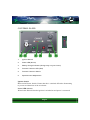
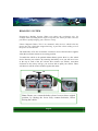
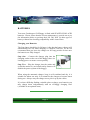
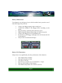
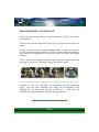
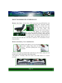
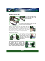
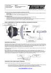
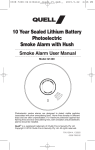
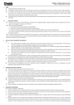
The Grasshopper
Golf Buggy
Owners Manual
Classic - Classic SE - Junior
TECHNICAL SPECIFICATION
Model:
Power:
Transmission:
Speed Control:
Direction Control:
Safety Features:
Climbing Ability:
Brakes:
Battery Charging:
Batteries:
Battery Charger:
Body:
Chassis:
Tyres:
Turning Radius:
Overall Height:
Overall Width:
Overall Length:
CLASSIC , CLASSIC SE & JUNIOR
Twin 24 Volt Permanent Magnet 300 Watt
D.C. Motors
Direct Drive Through 30:1 Reduction Gearboxes
Twist grip step-less control for smooth operation
up to max. 8mph.
Forward/Reverse switch conveniently located on
the main control panel.
Piezo reverse warning horn .
1:3 Gradient.
Non-fading regenerative braking
plus electromagnetic parking brake.
Charging unit plugs directly into rear of buggy.
Two sealed lead acid 12 V x 80/85amp coupled in
series
8 Amp, 24 Volt with automatic cut-out when
charging complete.
Hand Made in Non-Rusting Glass Reinforced
Plastic
MIG Welded High Tensile Steel, With Corrosion
Protection
13” x 6.5 x 6” Tubeless.
102” (140” Junior)
34”
36” (27” or 30” Junior)
48” (50” Junior)
All Specifications subject to change without notice
Page 2
INTRODUCTION
Thank you for choosing a Grasshopper Golf Buggy, a product designed
and engineered by Leisure Karts (UK) Ltd.
This manual provides all the information you will require to drive your
buggy safely and to see that it continues to perform perfectly.
Ensure that you read and understand this manual thoroughly.
It is recommended that insurance cover to include third party liability,
theft and accidental damage should be taken. Some household insurance
companies will give extended cover.
We can supply details of ‘Fish Insurance’ an independent insurance
company recommended by Leisure Karts (UK) Ltd.
The Grasshopper Junior & Classic SE
Page 3
CONTROL PANEL
1
2
3
4
5
6
1.
Ignition Switch
2.
Power LED (Green)
3.
Battery Charge Indicator (Design may vary see insert)
4.
Forward / Reverse LED (Red)
5.
Forward / Reverse Switch
6.
Speed Control Adjustment
Ignition Switch
Main On/Off Power Switch. Ensure that this is switched off before dismounting
to prevent accidental use of the accelerator.
Power LED (Green)
When lit this indicates that the ignition is switched on and power is connected
Page 4
Battery Charge/Power Indicator
There are two different types, both consist of a series of LED lights., when fully
charged the top or right hand light (dependant on type), will be illuminated As
battery charge is used, the light will move either down or to the left. It is advisable to leave the course when the final light is illuminated.
Forward / Reverse LED (Red)
Indicates when the reverse mode switch has been selected, it operates in
conjunction with a warning horn.
Forward/Reverse Switch:
This is a rocker switch, when pressed at the top forward mode is selected, when
pressed at the bottom reverse mode will be selected.
Speed Control Adjustment:
When turned fully, counter-clockwise, the buggy will move forward at 2 m.p.h.
By rotating the control clockwise the speed can be increased to a maximum of
8 m.p.h.
DRIVING THE VEHICLE
Sit comfortably on the vehicle and ensure feet are located on the foot tray. Place
both hands upon the handlebars. The steering column can be moved towards or
away from the driver to suit individual comfort.
The place the key in ignition switch on the control panel. Turn it 90 degrees
clockwise to connect the power. The charge/power indicator will light up to
indicate power on and will show the battery charge status.
Select forward or reverse mode and turn the
accelerator grip gently towards you.
The further the grip is turned the faster the
vehicle will travel. To slow down, gently
return the grip to its resting position.
The grip is spring loaded and if released will
immediately cause the vehicle to slow down
and stop.
Accelerator Twist Grip
Page 5
BRAKING SYSTEM
Regenerative Braking System: When you release the accelerator grip, for
example when travelling down slopes or up hills, the motor provides a reverse
pull effect, rapidly bringing your vehicle to a stop.
Electro Magnetic Brake: This is an automatic safety device, which locks the
motor once the vehicle has stopped moving, it prevents it from rolling even if
the power is switched off.
The brake lifts off as the accelerator is turned to move forward and re-applies
when the accelerator returns to its resting position.
To enable the vehicle to be pushed without battery power there is a free wheel
device fitted to your vehicle. By removing the battery cover you will see a lever
at the top of each of the two electric drive motors (see below), turn them
clockwise as far as they will go, you are now able to push your vehicle. There
will however still be some resistance against the motor.
Note: Ensure you return the brake release levers to there original
position, by turning the levers fully counter-clockwise, before
driving the vehicle.
Page 6
BATTERIES
Your new Grasshopper Golf Buggy is fitted with SEALED LEAD ACID
batteries. Please ensure that the correct maintenance is carried out as per
the information below to prolong their life. DO NOT fit other types of
battery without first checking compatibility with Leisure Karts.
Charging your Batteries
The first charge should be for 24 hours. After that the battery charger will
automatically cut out when charging is complete, however, we do not
recommend that you leave the charger on for long periods of time once
the batteries are fully charged.
Step One – Connect the charger plug into the
charging socket on the rear of the Buggy, there is a
locating groove to ensure correct polarity.
Step Two – Plug the charger into the mains and
switch the mains on, (an in-built safety feature will
disable the power system of the buggy).
When using the automatic charger, keep it well ventilated and dry, it is
suitable for indoor use only. It is normal for the charger to become warm
during use. Always carry the charger never pick it up by the cables.
If you have difficulty finding a suitable place to charge your batteries you
may charge them independently with an off-buggy charging lead.
(Available as an optional extra).
Page 7
Battery Maintenance
Your batteries are the heart of your vehicle and the better you take care of
them the longer they will last.
⇒
⇒
⇒
⇒
⇒
⇒
⇒
Charge your Buggy nightly when in daily use.
Connect the charger to the Buggy before switching on the
mains.
Keep the battery terminals and connectors clean.
When using the charger allow plenty of airflow around it.
Charge your Buggy in a well ventilated area.
Do not leave your Buggy uncharged, this will shorten the life
of the batteries
Only use the recommended charger.
Battery Life Expectancy
Many factors can significantly alter the performance of the batteries.
⇒
⇒
⇒
⇒
⇒
⇒
The weight of the occupant.
The type of terrain covered.
The style of driving.
Incorrect tyre pressure (we recommend 20 - 29 psi)
The age and condition of the battery.
The ambient temperature the vehicle is used in.
Page 8
TRANSPORTING YOUR BUGGY
One of the main design criteria for the Grasshopper Classic, was ease of
transportation.
There are two options dependant or the type of vehicle used to carry your
buggy.
Firstly, if you have a large family hatchback, MPV or estate car, then you
are able to load the buggy into the rear of the vehicle without dismantling,
other than removing the seat (even this may not be necessary with larger
vehicles).
This is achieved by placing ramps up to the rear of the vehicle and using
the buggies own power, driving the buggy up into the vehicle.
Visit www.grass-hopper.co.uk and view a short video demonstrating how.
Secondly, if your car is not able to accommodate the fully assembled
buggy, you can easily dismantle the buggy into manageable parts
allowing it to be placed into the boot of most cars - The only tool
required is a 13mm Spanner to undo the battery terminals.
Page 9
HOW TO DISMANTLE THE BUGGY
Remove the Seat - On the base of the seat stem you will find the seat
locking bolt. Turn this counter
clockwise to loosen the seat
from the frame. however the
lever can only rotate 180
degrees because of the body of
the buggy, to overcome this,
the lever has a ratchet system to allow further
movement. Pull the lever away from the post
turn it back to the original position and allow it
to spring back, once again turn the lever to
unscrew the bolt until the seat can be removed. To re-assemble reverse
the procedure.
Remove the Battery Cover and Batteries
Remove the battery cover by releasing
the three spring clips (four for the
Junior) and then pulling the cover
upwards.
Unscrew the battery terminal nuts and lift away the cables (only one nut
needs to be removed from the short link cable).
Lift batteries vertically from the frame and stand them in a secure
position.
Page 10
Disconnect The Power Plug
This is the plug that carries
power from the rear to the
front of the buggy.
It is located at the bottom left side near the
foot tray or between the batteries.
There are two types of plug. One simply pulls away
from the socket, there is a locating grove to ensure
correct pin alignment on re-assembly. The other type of
plug requires twisting a locking sleeve then pulling
apart, again a grove ensures correct pin alignment
Dismantle The Chassis
To separate the vehicle in
two, pull up the spring
loaded plunger (located at
the centre of the vehicle)
and pull the front section
from the rear.
The steering column can be lowered ready
for placing into a vehicle. The
components of the buggy are heavy and
care with posture should be taken when
lifting – where possible ask for assistance.
Page 11
When lifting the sections, do not lift by the bodywork. Always use the
framework for gripping. The Junior Model has an integral lifting handle
built into the rear of the chassis.
It may be advantageous to release the brakes to assist in manoeuvring the
rear section on the floor or in the car.
HOW TO ASSEMBLE THE BUGGY
Assemble the Chassis - Ensure that both halves are square to each other.
Locate the front stainless steel draw bar into to corresponding slot on the
rear section. Slide the two halves together until the spring plunger locates
into a retaining hole on the draw bar. Three holes have been provided to
suit individual requirement for leg length.
Connect the Power Plug – The power plug connecting the front and rear
sections should be re-connected.
Replace Batteries – One at a time, place the batteries into the chassis. On
Junior model the terminals should be towards the centre. On Classic and
Classic SE Models the terminals should be towards the rear.
Ensure the Brakes are on – If the brakes have been released, ensure that
the brake locking levers have been returned fully counter-clockwise.
Replace Battery Cover – Carefully replace the battery cover and click
spring clips into position.
Replace the Seat – Line up the seat stem into the seat tube on the chassis
and allow it to drop into position. Re-fasten the seat locking bolt until
tight.
Page 12
HOW TO KEEP YOUR BUGGY IN GOOD CONDITION
Apart from having your buggy serviced by an authorised Grasshopper
Dealer, you can help its condition by observing the following home
maintenance guidelines.
Bodywork:
Wash with a sponge and car shampoo.
Clean regularly with a general purpose spray or cream but not an abrasive
cleaner.
Do not use a power jet wash or hose pipe.
Batteries:
Ensure they are kept fully charged.
Keep terminals clean and lightly greased.
Tyres:
Check the tread and remove any stones or flints. The tyres should be
inflated to 29lbs psi (170 kilo Pascal’s).
On hard ground the pressure can be lowered to 20lbs psi
(147 kilo Pascal’s) for a more comfortable ride.
Seat System:
Make sure it is clean from dirt and grit.
Electrical Plugs:
Make sure plugs are clean, dry and pushed fully home.
Page 13
TROUBLE SHOOTING
The Buggy has no Power Indication.
⇒
Check the front to rear connector is pushed home correctly.
⇒
Check that the battery connectors are clean and securely
fastened.
⇒
Check the ignition is switched on.
⇒
Check the batteries are fully charged.
⇒
Check connections are secure. This is best done by
disassembling the buggy and turning it onto its side.
When connected only the red power LED on the charger illuminates.
⇒
Check the charger is plugged into mains and switched on.
⇒
Check the charger is plugged securely into the socket.
⇒
Check the fuse on the charger.
⇒
Check that the connector between the socket and the
controller has not come apart. This is best done by
disassembling the buggy and turning it onto its side.
Page 14
The Battery has fully charged but the power indicator shows less
than full.
⇒
Check that the front to rear connector is dry and pushed fully
home. Pull the plug in and out three or four times to ensure
good clean contact.
The steering column swings backward and forward seeming loose.
⇒
⇒
⇒
Remove the front cover from the handlebars
by unscrewing the two wing-nuts on the
drivers side of the handlebars and pulling the
cover forward.
Pull the rubber gaiter up to expose the
handlebar securing bolt.
tighten the bolt until movement seems stiff,
replace the rubber gaiter and front cover.
If after any of the above actions the buggy still does not function
correctly, contact your supplying dealer to arrange an inspection or
contact Grasshopper Golf Buggies directly on (+44) 01623 514700
WARNING: The wiring, drive motors, electronic
controller and gearbox all require specialist training
to service or repair. Your authorised Grasshopper
engineer has been trained to carry out such repairs.
Unauthorised tampering with the components may
invalidate your warranty.
Page 15
Leisure Karts (UK) Ltd
86-88 Mason Street
Sutton-in-Ashfield
Nottinghamshire
NG17 4HP
Tel: (+44) 01623 404730
email: [email protected]
web: www.grass-hopper.co.uk