1
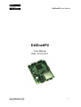
DAEnetIP2 User Manual
DAEnetIP2
User Manual
Date: 22.03.2012
-1-
DAEnetIP2 User Manual
Content
1. Basic features ..................................................................................................3
2. Technical parameters........................................................................................4
3. Application examples.......................................................................................5
4. Product installation...........................................................................................6
5. Default Settings................................................................................................ 7
6. Connectors and LED indicators........................................................................9
7. Web access..................................................................................................... 11
8. SNMP access..................................................................................................17
9. Appendix 1. Power supply............................................................................. 23
10. Appendix 2. Connections............................................................................. 24
11. Appendix 3. I/O Ports...................................................................................25
12. Appendix 4. Connecting analog temperature sensors.................................. 26
13. Appendix 5. Mechanical draw......................................................................29
-2-
DAEnetIP2 User Manual
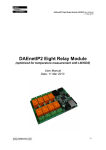
1. Basic features
DAEnetIP2 is multifunctional device for management and control. It could be
used for industrial automatization, access control, fire and security systems. It
is suitable also for controlling relay boards and tracking different sensors via
internet.
• 10 Mb Ethernet interface with Link/Activity Led
• Low power consuption (<50mA/12V)
• Power supply 7.5 - 25V
• Standart protocols: ARP, IP, ICMP (ping), SNMP v1
(snmpget/snmpset/snmp traps), Web, TFTP (firmware update)
• Two MAC addresses protection
• It can be configurated with SNMP requests
• 2x8 digital outputs
• 1x8 combined analog or digital inputs with 10 bit ADC (0-3.3V)
• Integrated WEB server with authorization for all functions/parameters
access
• Size – 43mm x 55mm
-3-
DAEnetIP2 User Manual
2. Technical parameters
Parameter
Value
Size
43x55mm
Power supply voltage
7.5 - 25VDC
CPU power supply (output level 3.3VDC)
3.3V
Digital outputs count
16
Analog inputs count
8 (10bit ADC, Vref=3.3V)
1)
8
Digital inputs count
Default settings jumper
Yes
LED (Link, Activity,
Yes
Power On)
Save I/O states
Yes
DHCP
Yes
Network parameters
IP/Mask/Default gateway
MAC lock (protection)
Yes
SNMPv1
Yes (snmpget,snmpset)
Read-Write Community String
Yes
Read-Only Community String
Yes
SNMP traps
Yes
SNMP I/O access commands
Yes
Web server for configuration/access
Yes
TFTP client for remote firmware update
Yes
Command for TFTP update
Yes
(Web,SNMP)
Enable/Disable TFTP update
Yes
1) Digital inputs are the analog inputs, but the input voltage is converted to 1 or 0
-4-
DAEnetIP2 User Manual
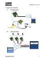
3. Application examples
3.1.
Remote control
DAEnetIP2
PC
Relay Board
Power supply
Electrical device
Data acquisition
Sensor
DAEnetIP 2
MP
SN
SNMP
DAEnetIP 2
Sensor
Sensor
DAEnetIP 2
SN
MP
SN
MP
Tr
ap
3.2.
SNMP Monitoring
Software
SNMP Trap
SNMP
Web browser
H
TT
P
HTTP
-5-
DAEnetIP2 User Manual
4. Product installation
1. Connect the DAEnetIP2 with PC or router with UTP cable.
2. Supply the DAEnetIP2 controller (12VDC stabilized recommend)
3. Your PC IP should be in the DAEnetIP2 network initially. So it is
recommend to be 172.16.100.1. If you have router make the router IP
172.16.100.3
4. Open web browser and type 172.16.100.2 – username/password are
“admin”/”admin”
5. Access the module via Web.
-6-
DAEnetIP2 User Manual
5. Default Settings
5.1.
Table with default settings
These are the default (factory) settings of DAEnetIP2. When you buy the
controller you will receive it with these settings.
Parameter
(according Web pages)
DHCP
IP
Mask
Gateway
VLAN ID
VLAN mode
Access MAC 1,2
SNMP access to IP
SNMP Read-only community string
SNMP RW community string
SNMP/Web Access network IP
SNMP/Web Access network Mask
Reset I/O ports on restart
TFTP update
TFTP Server IP
Broadcast Frames
Web Server
SNMP traps target host
SNMP traps community
Low/High Analog Trap Threshold
Analog Events – Low, High, Acc
Web user/password
Value
Disabled
172.16.100.2
255.255.255.0
172.16.100.1
1
Disabled
000000000000
Enabled
000000000000
private
172.16.100.1
0.0.0.0 (disabled)
Disabled
Enabled
172.16.100.1
Parse
Enabled
172.16.100.1
public
0/1023 (disabled)
None
admin/admin
-7-
DAEnetIP2 User Manual
5.2.
1.
2.
3.
4.
5.
6.
Steps for loading default settings
Turn off the power supply of the IP controller
Move the jumper from position 1 to position 2
Turn on the power supply of the IP controller
Move the jumper from position 2 to position 1
Turn off the power supply of the IP controller
Turn on the power supply of the IP controller
-8-
DAEnetIP2 User Manual
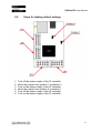
6. Connectors and LED indicators
6.1.
DAEnetIP2 ports view
-9-
DAEnetIP2 User Manual
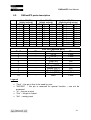
6.2.
Pin N
1
2
3
4
5
6
7
8
9
10
DAEnetIP2 ports description
Port JP3 (P3)
(digital outputs)
Bit
Func
Dir
1
Free
Out
2
Free
Out
3
Free
Out
4
Free
Out
5
Free
Out
6
Free
Out
7
Free
Out
8
Free
Out
GND PWR
GND PWR
Pin N
1
2
3
4
5
6
7
8
9
10
Bit
-
Port JP4 (P5)
(digital outputs)
Bit
Func
Dir
1
Free
Out
2
Free
Out
3
Free
Out
4
Free
Out
5
Free
Out
6
Free
Out
7
Free
Out
8
Free
Out
+3.3V PWR
GND
PWR
Port JP5 (P6)
(digital/analog inputs)
Bit
Func
Dir
1
Free
Ain
2
Free
Ain
3
Free
Ain
4
Free
Ain
5
Free
Ain
6
Free
Ain
7
Free
Ain
8
Free
Ain
+3.3V(Vref) PWR
GND
PWR
Port JP6 (system port)
Func
+3.3V
+3.3V
Reserved
Ping LED
Reserved
Target RST
Switch (RST)
Switch (SCL)
Switch (SDA)
GND
Dir
PWR
PWR
Out
Out
Out
Out
In/Out
PWR
Legend:
• “Free” – the pin is free to be used by user.
• “XXXXXX” - the pin is reserved for special function – can not be
accessed.
• “In” – the pin is input
• “Out” – the pin is output
• “Ain” – analog input
-10-
DAEnetIP2 User Manual
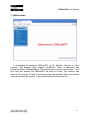
7. Web access
It is possible to configure DAEnetIP2 via IE, Mozilla, Chrome or other
browser. The browser must support JavaScript. There is username and
password (Basic Authentication). The web server has only one session – only
one user can access the DAEnetIP2 via web at a time. The session has
timeout 60 seconds if there is not access from the browser. After that another
user can access the module. This is done because of the security.
-11-
DAEnetIP2 User Manual
7.1.
Setup
7.1.1.
Firmware version
This is the current firmware version. Can not be changed
7.1.2.
MAC address
The MAC address of the module. Can not be changed
7.1.3.
IP address
The IP address of the module.
7.1.4.
Subnet Mask
The subnet mask of the module.
7.1.5.
Default Gateway
The Default gateway of the module.
-12-
DAEnetIP2 User Manual
7.1.6.
VLAN
DAEnetIP2 can work with normal or tagged packets (IEE 802.11q). It supports
the whole set of 12bit VLAN tags.
7.1.7.
DHCP
The IP,MASK and Gateway can be broght by DHCP server.
7.1.8.
MAC filtering
DAEnetIP2 has MAC protection. This means that if it is enabled it can be
accessed from one/two MAC addresses. For disable the MAC protection,
the MAC must be 000000000000.
7.1.9.
SNMP/Web Access network
This function determine which IP/MASK network will access the module
through SNMP and Web. The filtering is for SNMP, Web, ARP, ICMP, DHCP.
Note that MAC protection is with higher priority than SNMP/Web access
protection.
7.1.10. SNMP settings
This section is for enable/disable SNMP access and SNMP community strings.
7.1.11. ICMP monitoring modes
ICMP settings.
7.1.12. TFTP firmware update
DAEnetIP2 has TFTP client for firmware update. When the command is
initiated, the DAEnetIP2 module connects to the TFTP server and starts
downloading the firmware version. After checking if there is connection with
the TFTP server and if the file is correct the firmware will be updated and the
module will be rebooted.
7.1.13. Broadcast frames
In this mode DAEnetIP2 does not response of frames with MAC address FFFF-FF-FF-FF-FF. This allows DAEnetIP2 to hide from the world because it
doesn’t respond to ARP requests
7.1.14. Web server
Enable/disable web access.
-13-
DAEnetIP2 User Manual
7.2.
SNMP traps
SNMP traps can be generated from Analog inputs if its level crosses the
given limits. If the limits are 0 and 1023 then there will not be any traps from
this input. The message gives information from which input is this trap and
what is the input level value. If several events are generated, DAEnetIP2
sends their traps in order they have been generated.
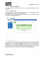
7.3.
Analog events
DAEnetIP2 Analog inputs could be attached to P5 digital output port. When
analog input is changed the corresponding digital output can react. There are
4 modes:
7.3.1.
Mode “Low”
The output will become “1” if the input level is less than Low Threshold and
sets the previous state when the input level is over Low Threshold.
7.3.2.
Mode “High”
The output will be set if the input level is higher than High.
-14-
DAEnetIP2 User Manual
7.3.3.
Mode “Low/High”
The output will be set if the input level is out of the range with High and Low
Threshold.
7.3.4.
Mode “Acc”
The output will be set if the input level is less than Low Threshold and will be in
old state after input level is over High Threshold.
This function does not affect to SNMP traps but the same Threshold values
are used for sending SNMP traps.
7.4.
I/O Ports
P3 and P5 are two 8 channel digital output ports. P6 is 8 channel 1024 bit
analog input port. The reference voltage is 3.3VDC. Also P6 can be used as
digital input port. If the value is greather than 1.65V this is “1”, otherwise “0”.
Via snmp this is parameter pctrlP6byte.0. When this command is send the
module will return one byte with converted analog input values “1” or “0”. In
this way the port can be used either as analog either as digital inputs.
-15-
DAEnetIP2 User Manual
7.5.
Account
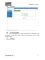
7.6.
Firmware Update
This command starts firmware update. The DAEnetIP2 will download the
firmware file from the TFTP server given in Setp section. After that the device
will be rebooted.
7.7.
Reboot
Reboots DAEnetIP2.
-16-
DAEnetIP2 User Manual
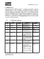
8. SNMP access
DAEnetIP2 supports SNMPv1 protocol – snmpget and snmpset. It may be
configured/read all the parameters via these commands. Read-only
community string is used for reading and Read-Write Community String is
used for changing the parameters. Note that it is not possible using of
snmpwalk. Parameters that can be changed, are grouped according to their
functions in the tables below. To obtain a valid OID number it is necessary to
replace the “x” symbol with the prefix ”.1.3.6.1.4.1.19865”. Also all the snmp
commands are descriped in the file DAEnetIP2.mib. All the functions can be
accessed via SNMP and WEB
8.1.
Configuration settings
OID
x.1.1.1.0
Name
cfgIP
Access
read-write
x.1.1.2.0
cfgMAC
read-only
x.1.1.3.0
cfgVLANTag
read-write
x.1.1.4.0
cfgPassword
read-write
x.1.1.5.0
cfgMACLock1
read-write
x.1.1.6.0
cfgMACLock2
read-write
x.1.1.8.0
cfgVersion
read-only
x.1.1.9.0
cfgMode
read-write
Description
IP Address of
DAEnetIP2 module
MAC address of
DAEnetIP2 module
VLAN ID (12bit) in
VLANEnabled mode
Read-Write community
string (password)
MAC address of first
remote machine allowed
to access DAEnetIP2
module
MAC address of second
remote machine allowed
to access DAEnetIP2
module
Firmware version,
LSB=VER_MINOR,
MSB=VER_MAJOR
Contains different bit
flags for DAEnetIP2
operating modes:
ENABLED_BIT – bit0,
BROADCAST_DISABL
E-bit1,
VLAN_TAG_ENABLEbit2,
NO_LARGE_PACKETS
-bit3,
Syntax
IpAddress
PhysAddress
INTEGER(0..4
095)
OCTET
STRING (SIZE
(4..12))
PhysAddress
PhysAddress
INTEGER(0..6
5535)
INTEGER(0.
.255)
-17-
DAEnetIP2 User Manual
PINGRESTART_ENAB
LE-bit4,
SWITCH_CONTROLbit5,
SECONDARY_TARGE
T-bit6,
USE_ANALOG_PINSbit7
x.1.1.10.0
cfgReset
read-only
Read of this OID
causes rest of
DAEnetIP2 module
NULL
x.1.1.11.0
cfgNewMode
read-write
Contains different bit
flags for DAEnetIP2
operating modes:
SAVE_IOPORTS – bit0,
PING_LED – bit1,
PING_TIMEOUT_IORE
SET – bit2,
TFTP_UPDATE – bit3,
DHCP_CLIENT – bit4.
MONITOR_TIMEOUT_
RESTART – bit5,
WEB_SERVER – bit6,
SWITCH_RESTART –
bit7
INTEGER(0..2
55)
x.1.1.14.0
cfgDefGW
read-write
IpAddress
x.1.1.15.0
cfgNetMask
read-write
x.1.1.17.0
cfgReadOnlyP
assword
read-write
IP Address of Default
Gateway
IP Network Subnet
Mask
Read-only community
string (password)
x.1.1.18.0
cfgTrapServerI
P
cfgTrapPassw
ord
read-write
x.1.1.20.0
cfgAccessIP
read-write
x.1.1.21.0
cfgAccessMas
k
read-write
x.1.1.32.0
cfgTFTPServe
rIP
read-write
x.1.1.19.0
read-write
Remote IP address of
TRAP manager
Community string for
trap messages
IP address of network
class allowed to access
DAEnetIP2
Mask of network class
allowed to access
DAEnetIP2
Remote IP address of
TFTP server for
IpAddress
OCTET
STRING (SIZE
(4..12))
IpAddress
OCTET
STRING (SIZE
(4..12))
IpAddress
IpAddress
IpAddre
ss
-18-
DAEnetIP2 User Manual
x.1.1.33.0
cfgUpdateFirm
ware
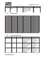
8.2.
Analog traps
OID
x.1.1.122.1.0
x.1.1.122.2.0
x.1.1.122.3.0
x.1.1.122.4.0
x.1.1.122.5.0
x.1.1.122.6.0
x.1.1.122.7.0
x.1.1.122.8.0
x.1.1.122.9.0
x.1.1.122.10.0
x.1.1.122.11.0
x.1.1.122.12.0
x.1.1.122.13.0
x.1.1.122.14.0
x.1.1.122.15.0
x.1.1.122.16.0
8.3.
read-only
firmware update
Read of this OID causes NULL
initiation of firmware
update procedure,
according to system
settings
Name
atrPin1Low
atrPin1High
atrPin2Low
atrPin2High
atrPin3Low
atrPin3High
atrPin4Low
atrPin4High
atrPin5Low
atrPin5High
atrPin6Low
atrPin6High
atrPin7Low
atrPin7High
atrPin8Low
atrPin8High
Access
read-write
read-write
read-write
read-write
read-write
read-write
read-write
read-write
read-write
read-write
read-write
read-write
read-write
read-write
read-write
read-write
Description
Pin low threshold
Pin high threshold
Pin low threshold
Pin high threshold
Pin low threshold
Pin high threshold
Pin low threshold
Pin high threshold
Pin low threshold
Pin high threshold
Pin low threshold
Pin high threshold
Pin low threshold
Pin high threshold
Pin low threshold
Pin high threshold
Syntax
INTEGER(0..1023)
INTEGER(0..1023)
INTEGER(0..1023)
INTEGER(0..1023)
INTEGER(0..1023)
INTEGER(0..1023)
INTEGER(0..1023)
INTEGER(0..1023)
INTEGER(0..1023)
INTEGER(0..1023)
INTEGER(0..1023)
INTEGER(0..1023)
INTEGER(0..1023)
INTEGER(0..1023)
INTEGER(0..1023)
INTEGER(0..1023)
Description
Defines reaction on
respective P5 output
pin when voltage is
compared to
thresholds
Defines reaction on
respective P5 output
pin when voltage is
compared to
thresholds
Defines reaction on
respective P5 output
pin when voltage is
compared to
thresholds
Syntax
INTEGER
{ None(0),
Low(1), High(2),
LowHigh(3),
Acc(4) }
INTEGER
{ None(0),
Low(1), High(2),
LowHigh(3),
Acc(4) }
INTEGER
{ None(0),
Low(1), High(2),
LowHigh(3),
Acc(4) }
Anolog-to-P5 Events
OID
x.1.1.121.1.0
Name
aevPin1
Access
read-write
x.1.1.121.2.0
aevPin2
read-write
x.1.1.121.3.0
aevPin3
read-write
-19-
DAEnetIP2 User Manual
x.1.1.121.4.0
aevPin4
read-write
x.1.1.121.5.0
aevPin5
read-write
x.1.1.121.6.0
aevPin6
read-write
x.1.1.121.7.0
aevPin7
read-write
x.1.1.121.8.0
aevPin8
read-write
8.4.
OID
x.1.2.1.0
x.1.2.2.0
x.1.2.3.0
8.5.
Defines reaction on
respective P5 output
pin when voltage is
compared to
thresholds
Defines reaction on
respective P5 output
pin when voltage is
compared to
thresholds
Defines reaction on
respective P5 output
pin when voltage is
compared to
thresholds
Defines reaction on
respective P5 output
pin when voltage is
compared to
thresholds
Defines reaction on
respective P5 output
pin when voltage is
compared to
thresholds
INTEGER
{ None(0),
Low(1), High(2),
LowHigh(3),
Acc(4) }
INTEGER
{ None(0),
Low(1), High(2),
LowHigh(3),
Acc(4) }
INTEGER
{ None(0),
Low(1), High(2),
LowHigh(3),
Acc(4) }
INTEGER
{ None(0),
Low(1), High(2),
LowHigh(3),
Acc(4) }
INTEGER
{ None(0),
Low(1), High(2),
LowHigh(3),
Acc(4) }
Description
I/O port data
I/O port data
I/O port data
Syntax
INTEGER(0..255)
INTEGER(0..255)
INTEGER(0..255)
Control ports
Name
pctrlPort3
pctrlPort5
pctrlPort6
Access
read-write
read-write
read-write
Control port P3 (Digital outputs)
OID
x.1.2.1.1.0
Name
pctrlP3pin1
Access
Description
readPort3 pin1 data
write
x.1.2.1.2.0
pctrlP3pin2
readwrite
Port3 pin2 data
x.1.2.1.3.0
pctrlP3pin3
readwrite
Port3 pin3 data
Syntax
INTEGER
{ High(1),
Low(0) }
INTEGER
{ High(1),
Low(0) }
INTEGER
{ High(1),
Low(0) }
-20-
DAEnetIP2 User Manual
x.1.2.1.4.0
pctrlP3pin4
readwrite
Port3 pin4 data
x.1.2.1.5.0
pctrlP3pin5
readwrite
Port3 pin5 data
x.1.2.1.6.0
pctrlP3pin6
readwrite
Port3 pin6 data
x.1.2.1.7.0
pctrlP3pin7
readwrite
Port3 pin7 data
x.1.2.1.8.0
pctrlP3pin8
readwrite
Port3 pin8 data
x.1.2.1.33.0
pctrlP3byte
readwrite
I/O port data as
single byte
8.6.
INTEGER
{ High(1),
Low(0) }
INTEGER
{ High(1),
Low(0) }
INTEGER
{ High(1),
Low(0) }
INTEGER
{ High(1),
Low(0) }
INTEGER
{ High(1),
Low(0) }
INTEGER(0..255)
Control port P5 (Digital outputs)
OID
x.1.2.2.1.0
Name
pctrlP5pin1
Access
read-write
Description
Port5 pin1 data
x.1.2.2.2.0
pctrlP5pin2
read-write
Port5 pin2 data
x.1.2.2.3.0
pctrlP5pin3
read-write
Port5 pin3 data
x.1.2.2.4.0
pctrlP5pin4
read-write
Port5 pin4 data
x.1.2.2.5.0
pctrlP5pin5
read-write
Port5 pin5 data
x.1.2.2.6.0
pctrlP5pin6
read-write
Port5 pin6 data
x.1.2.2.7.0
pctrlP5pin7
read-write
Port5 pin7 data
x.1.2.2.8.0
pctrlP5pin8
read-write
Port5 pin8 data
x.1.2.2.33.0 pctrlP5byte
read-write
I/O port data as
Syntax
INTEGER
{ High(1),
Low(0) }
INTEGER
{ High(1),
Low(0) }
INTEGER
{ High(1),
Low(0) }
INTEGER
{ High(1),
Low(0) }
INTEGER
{ High(1),
Low(0) }
INTEGER
{ High(1),
Low(0) }
INTEGER
{ High(1),
Low(0) }
INTEGER
{ High(1),
Low(0) }
INTEGER(0..255)
-21-
DAEnetIP2 User Manual
single byte
8.7.
Returned values are from 10bit Analog to Digital
Convertor
OID
x.1.2.3.1.0
x.1.2.3.2.0
x.1.2.3.3.0
x.1.2.3.4.0
x.1.2.3.5.0
x.1.2.3.6.0
x.1.2.3.7.0
x.1.2.3.8.0
Name
pctrlP6pin1
pctrlP6pin2
pctrlP6pin3
pctrlP6pin4
pctrlP6pin5
pctrlP6pin6
pctrlP6pin7
pctrlP6pin8
Access
read-only
read-only
read-only
read-only
read-only
read-only
read-only
read-only
Description
ADC Channel 1
ADC Channel 2
ADC Channel 3
ADC Channel 4
ADC Channel 5
ADC Channel 6
ADC Channel 7
ADC Channel 8
Syntax
INTEGER(0..1023)
INTEGER(0..1023)
INTEGER(0..1023)
INTEGER(0..1023)
INTEGER(0..1023)
INTEGER(0..1023)
INTEGER(0..1023)
INTEGER(0..1023)
-22-
DAEnetIP2 User Manual
9. Appendix 1. Power supply
The minimal power supply is 7.5VDC. The maximum voltage is 25VDC. The
optimal voltage is 12VDC.
-23-
DAEnetIP2 User Manual
10.
Appendix 2. Connections
10.1.
Connection to PC
10.2.
Connection to router
-24-
DAEnetIP2 User Manual
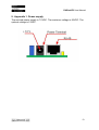
11.
Appendix 3. I/O Ports
They are not buffered and you should very carefully otherwise the MCU could
be damaged. They are digital inputs/outputs. The output level voltage is “1”
(3.3VDC) or “0” (0.25VDC) with consumption < 1.5mA. All inputs/outputs have
protection diodes to GND and +3.3VDC.
Below are given sample examples of I./O ports connections to external
devices. The first figure shows connection with 12V relay. The second shows
example for 5V TTL signal input. R2 is recommend because sometimes the
input signals are ‘tri-state”.
-25-
DAEnetIP2 User Manual
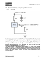
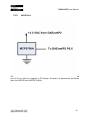
12.
Appendix 4. Using analog temperature sensors
12.1.
LM335Z
On the figure above it is shown LM335Z connection to DAEnetIP2 with several
resistors. LM335 may be assumed as zener diode it is necessary to limit the
current (that's why the 4.7K resistor is added). The biggest disadvantage of
LM335 is the high output voltage during 25°С – 3V. As DAEnetIP2 ADC works
in range of 0-3.3V, actually with directly connected LM335 it is not possible to
measure temperatures over 57°С. Moreover the output of LM 335Z can
exceed 3.3V and damage the ADC channel.
The easiest solution is using simple resistor divisor – 3:1 so the output voltage
during 25°С to be 1V. It is important the divisor resistance to be smaller because this
improves the ADC accuracy (but on the other hand it must be taken in mind also the
current in the sensor resistor). However the resistor divisor makes also the ADC
conversion bigger.
-26-
DAEnetIP2 User Manual
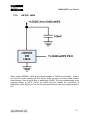
12.2.
LM35Z / LM34
When using LM35DZ / LM34 all the disadvantages of LM335 are avoided – there is
no need of current resistor (as this sensor does not work as zener diode) neither
output divisor. Also its initial error is better than LM335. The only disadvantage is the
minimal voltage is 4VDC (5VDC for LM34) and this makes the connection to
DAEnetIP2 more difficult (it can not be connected directly with only single jumper to
P6).
-27-
DAEnetIP2 User Manual
12.3.
MCP9700A
This sensor – MCP9700A works in range 2.3 – 5.5V and that allows to be supplied
from 3.3V pin which is mapped to P6 jumper. Generally its parameters are better
than the LM335Z and LM35DZ (LM34).
-28-
DAEnetIP2 User Manual
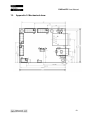
13.
Appendix 5. Mechanical draw
-29-