1
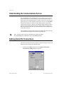
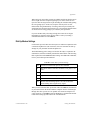
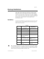
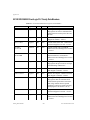
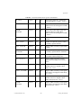
Creating & Managing
Communication Links
B
Certain object classes represent and such as PLCs, RTUs, and controllers.
LookoutDirect uses the term driver to refer to these types of object classes.
The functionality built into driver objects enables them to communicate with
the physical devices that they represent. LookoutDirect communicates with
the outside world primarily through driver objects.
The drivers are not separate applications. They work as any other object in the
LookoutDirect event–driven environment, except that they communicate
with external devices.
With traditional systems, a particular driver is assigned to a specific serial
port. In these configurations, multiple drives cannot share a single serial port.
LookoutDirect does not associate baud rate, data bits, parity, or stop bits with
a particular serial port. In this configuration, drivers that implement different
protocols and baud rates can use the same port and the same modem or radio
frequency (RF).
This capability allows you to mix and match PLCs, RTUs, and other devices
over a single RF without communications conflicts or special hardware. This
is possible because of LookoutDirect’s communication service. Objects use
the communications service to gain access to serial ports in an orderly and
timely fashion.
Some LookoutDirect driver objects communicate with physical devices through
dedicated hardware. These driver objects do not use serial ports but instead rely on their own
proprietary network cards for interfacing to the outside world. A few examples include
Modbus Plus (SA85 card), Data Highway (KT card), and DeltaTau (PMAC card). You do not
need to configure serial ports for these object classes. Refer to the appropriate object class
documentation in Online Help or the Reference manual to verify if a particular object class
uses a serial port.ion in Online Help.
Note
© Automationdirect.com
B-1
Getting Started Guide
Appensix B
Understanding the Communications Service
The LookoutDirect serial communication service allocates serial port usage
between driver objects. At the frequency of the object Poll Rate, a driver
object notifies the communications service that it needs to use a specific serial
port to poll a device. If the requested serial port is not in use, LookoutDirect
allocates the serial port to the driver object. When the driver object takes
control of the serial port, it defines port communications parameters such as
baud rate and protocol and polls its device. When polling is complete, the
driver object releases the port so the communications service can allocated it
to other driver objects.
You can uniquely configure each serial port for hardwired, radio, or dial–up
communications through the Serial Port Settings dialog box.
You must define serial port communication settings on both the
Development/Runtime and Runtime only LookoutDirect products.
Note
Defining Serial Port Connections
This section provides the necessary steps to configure serial port settings for
hardwired, radio, and dial–up communications.
1.
From the LookoutDirect menu bar, select Options Serial Ports...
The Serial Port Settings dialog box appears.
Getting Started Guide
B-2
www.Automationdirect.com
Appendix B
2.
In the Serial Port data field, select the communication port you are
defining. In this example we are using COM 1.
3.
Define the serial port parameters for the appropriate communication
port.
4.
Click on Accept to save the parameter changes for the serial port.
5.
Click on Quit to exit the dialog box.
Selecting the Serial Port
The Serial Port data field is a drop–down list box. Use it to select the
communication port you are defining. Windows supports up to nine serial
ports; however, most computers support only two serial ports without
additional hardware.
Setting the Receive Gap
The Receive gap setting is available for all serial connection types. This
number specifies the number of empty bytes (or amount of time) a driver
receives from a controller before the driver recognizes the end of a message
frame and asks for another message. Normally you should leave this at the
default setting of 20. However, if you are experiencing garbled
communication alarms, you might try increasing this number to allow more
dead time before LookoutDirect decides it has received a complete message.
For example, with a slow baud rate of 1200, you might have to increase the
Receive gap setting to approximately 30.
Hardwired Settings
Hardwired serial connections require no hardware handshaking for line
control. Use this setting for all serial communication types except dial–up
telephone and remote radio transceivers. You should also use this setting
when directly connecting to the Master Repeater on a radio system or through
a leased–line modem. Because a Master Repeater is a full duplex device that
does not require keying and unkeying of the frequency, it acts much like a
physically hardwired network. Other hardwired connection types include
RS–232, RS–422, RS–485, and leased telephone lines.
© Automationdirect.com
B-3
Getting Started Guide
Appensix B
RTS/CTS Handshaking Settings
RTS/CTS is a local hardware handshaking mechanism between the local
computer and the local communication device. Use the Radio (RTS/CTS)
serial connection when connecting the serial port to a device that requires
RTS/CTS hardware handshaking, such as a radio transceiver that must be
keyed up during data transmission and unkeyed during data reception. Other
half–duplex communication media such as RS–485 may require RTS/CTS
hardware handshaking.
When you select RTS/CTS hardware handshaking, LookoutDirect controls
the RTS, or request–to–send pin, and monitors the CTS, or clear–to–send pin,
during data transmission (pins 4 and 5 on a 25–pin RS–232 connector).
Therefore, you must have at least the RTS pin (pin 4) wired straight through
on your RS–232 cable. The CTS pin (pin 5) is optional.
LookoutDirect initiates a serial transmission on an RTS/CTS port by first
asserting RTS to key the radio. It then begins monitoring the state of the CTS
pin. When the radio transmitter is fully keyed and ready to transmit, the radio
asserts CTS and immediately begins data transmission. If the radio does not
assert CTS within the CTS timeout setting (default is 100 msecs),
LookoutDirect assumes the radio is ready to transmit and transmits anyway.
The CTS timeout setting is the maximum amount of time that LookoutDirect
waits after asserting RTS for CTS before transmitting. Most radios typically
take between 10 and 80 milliseconds to key up. Consult your radio
specifications and DIP switch settings to determine the key–up delay on your
radio.
If your radio can assert CTS when it is ready to transmit, add about 50
milliseconds to the radio key–up delay specification and use this total value
for the CTS timeout. If your radio does not assert CTS, you should begin by
adding about 20 milliseconds to your radio key-up time. Then increase this
value in 10 millisecond increments until the remote radio begins to correctly
receive the first bytes of the message.
Some radios may assert CTS before they are actually ready to transmit. In this
case, disconnect the CTS line (pin 5 on a 25–pin RS232 connector) and set
the CTS timeout to a value high enough to let the radio fully key before
transmission.
After it transmits the last byte of data, LookoutDirect continues to assert RTS,
keeping the radio keyed until the RTS delay off time period expires. You
should set this value to the default of zero milliseconds so that LookoutDirect
un-keys the radio as soon as possible to prepare to receive the response.
Getting Started Guide
B-4
www.Automationdirect.com
Appendix B
When un-keyed, most radios generate an audible squelch tail that the remote
device might decode as unexpected garbage bytes. Some remote devices
reject the entire message instead of just decoding the valid data and ignoring
the extra garbage bytes. In this case, keep the radio keyed for several
milliseconds using the RTS delay off setting. This time period delays the
squelch tail long enough for the remote device to recognize the last data frame
as valid before receiving garbage bytes caused by the squelch tail.
If you set the RTS delay off setting too high, the remote device begins
transmitting its response before the local radio is un-keyed, causing a
communication alarm in LookoutDirect.
Dial-Up Modem Settings
Use the Dial–up serial connection when you use a modem in conjunction with
a switched telephone line (not leased line). You can customize the dial–up
settings for your particular modem and phone line.
The default Dialing prefix settings are based on the Hayes Corporation AT
command set, which is an industry standard for data modems. The following
table explains the LookoutDirect default settings. For additional commands,
refer to your modem operation manual.
Table B-1 Default Dial-Up Modem Settings
AT
Attention code that must precede all commands
D
Dial phone number with these modifiers: P for pulse; T for
tone
En
Local echo mode: E for no echo
Mn
Speaker on or off: M for speaker always off
Vn
Verbal or numeric result codes: V for numeric result codes
Xn
Result code and dialing options: X4 waits for dial tone
before dialing and recognizes busy signal.
When you use an external dial–up modem with LookoutDirect, the DTR line
in your cable between the modem and the computer must be wired straight
through. This line is pin 20 on a 25–pin RS–232 connector and pin 4 on a
9–pin connector. LookoutDirect uses the DTR line to command the modem
to disconnect (hang up) and return to the command mode.
© Automationdirect.com
B-5
Getting Started Guide
Appensix B
Some factory modems are not configured to respond to the DTR line. After
LookoutDirect first successfully dials out to a remote modem and finishes the
polling cycle, it drops the DTR line but the modem remains connected. If the
modem does not respond after several seconds of attempting to raise and drop
the DTR line, LookoutDirect generates an alarm stating that the modem is not
responding. If you receive this alarm message, your modem is not configured
to monitor the DTR line.
The Hayes Corporation standard command for configuring the modem to
hang up and enter command mode upon loss of DTR is &D2. You can use a
terminal program to make this setting permanent on most modems by
entering the modem command AT&D2&W to store the setting permanently
in nonvolatile modem memory. Or you can just add &D2 into the Dialing
prefix. The default Dialing prefix is ATX4MVEDT, so you might change it to
AT&D2X4MVEDT.
Retries specifies the number of times LookoutDirect dials the specified phone
number and attempts to connect to the modem at the other end of the line. If
it fails to connect after the specified Retries, it generates an alarm and moves
on to the next phone number in the polling queue (if a queue has formed).
Wait for connection specifies the length of time LookoutDirect waits to
receive a connect signal back from the modem it is calling. The time period
begins when LookoutDirect first sends the local modem the dialing prefix
command. The time should be long enough for the local modem to receive a
dial tone, dial the phone number, allow the remote modem to pick up the line,
and send back a connect message. If the specified time is too short, your
system could be operating correctly but never make a connection.
Pause between calls is the length of wait time after hanging up before it sends
the local modem the next dialing prefix signal. If the specified time is too
brief, your system may not hang up the existing call but instead attempt to call
the next number.
Specific modems, radios, and local phone lines may operate faster or slower than the
default settings. You may need to use a trial–and–error approach to find the best settings for
your system.
Note
Getting Started Guide
B-6
www.Automationdirect.com
Appendix B
DirectLogic Data Members
Protocol driver objects contain a great deal of data. V–memory registers,
inputs, outputs, internal control relays are all included within this object.
Therefore, as soon as you create a DirectLogic object you have immediate
access to the entire data member set of the object. As with all LookoutDirect
drivers, you can access I/O points and other data through data members. The
following tables contain data members currently supported by the
DirectLogic object class.
Data Modifiers
In order to have the DSData Server peform data conversions as it moves data
in and out of the PLC, the data modifier presented in the following can be
added to the end of a data item.
Table B-2
Recognized by
(DirectLogic PLC)
Modifier
Description
No modifier
Decimal value (16 bits)
All
:D
Decimal value (32 bits)
All
:B
Convert to BCD (16 bits)
All
:DB
Convet to BCD (32 bits)
All
:nn
Read a specific bit in a
Word (not available for
writing bits)
All
:R
Convert to Real (32 bits)
DL250, DL350, and
DL450
:W
Word (16 bits)
DL330, DL330P, DL340,
and DL305
:WB
Word (16 bits), converts
to BCD
DL330, DL330P, DL340,
and DL305
The range of data members shown in the following tables may be beyond the capacity
of the specific DirectLogic PLC or compatible CPU that you are using OR may not include
some of the data members shown. Consult the appropriate PLC family user manual for the
specific memory types and ranges available for your PLC CPU.
Note
© Automationdirect.com
B-7
Getting Started Guide
Appensix B
05/105/205/350/405 DirectLogic PLC Family Data Members
Table B-3. 05/105/205/350/405 DirectLogic PLC Data Members
Data Member
Type
Read
Write
Description
Activated
Logical
Yes
No
Object-generated signal when TRUE, this
flag signifies an active5 communication
connection between the process file and
the PLC.
C0 – C3777
Logical
Yes
Yes
Control Relays – addressed in octal and
mapped to V40600 – V40777.
CT0 – CT377
Logical
Yes
Yes
Counter status (done) bits – addressed in
octal and mapped to V41140 – V41157
CTA0:B –
CTA377:B
Numeric
Yes
Yes
Counter current value words BCD –
addressed in octal and mapped to V01000
– V01377
CTA0:DB –
CTA376:DB
Numeric
Yes
Yes
Counter current value double words (two
adjacent addresses; 32-Bit) BCD –
addressed in octal and mapped to V01000
– V01377
Failed
Logical
Yes
No
Object-generated signal when TRUE, this
flag signifies the process file is no longer
communicating with the PLC.
GX0 – GX3777
Logical
Yes
Yes
Remote I/O Inputs – addressed in octal
and mapped to V40000 – V40177
GY0– GY3777
Logical
Yes
Yes
Remote I/O Outputs – addressed in octal
and mapped to V40200 – V40277
Paused
Logical
Yes
No
Object-generated signal when TRUE, this
flag signifies that the communication
connection has paused but is still active
and will go FALSE when its paused
condition is satisfied. Usually caused by
modifying the Link while it is in use.
S0 – S1777
Logical
Yes
Yes
Stage status (active) bits – addressed in
octal and mapped to V41000 – V41077
SP0 – SP777
Logical
Yes
No
Special Relays (system status bits) –
addressed in octal and mapped to V41200
– V41237
Getting Started Guide
B-8
www.Automationdirect.com
Appendix B
Table B-3. 05/105/205/350/405 DirectLogic PLC Data Members
T0 – T0377
Logical
Yes
Yes
Timer status (done) bits – addressed in
octal and mapped to V41100 – V41117
TA0:B – TA377:B
Numeric
Yes
Yes
Timer current value words BCD –
addressed in octal and mapped to V00000
– V00377
TA0:DB –
TA376:DB
Numeric
Yes
Yes
Timer current value double words (two
adjacent addresses; 32-Bit) BCD –
addressed in octal and mapped to V00000
– V00377
V0 – V41237
Numeric
Yes
Yes
Single (16-Bit) V-memory registers
decimal
V0:D – V41237
Numeric
Yes
Yes
Double (two adjacent registers; 32-Bit)
V-memory registers decimal
V0:B – V41237:B
Numeric
Yes
Yes
Single (16-Bit) V-memory registers BCD
0- 9999
V0:DB –
V41236:DB
Numeric
Yes
Yes
Double (two adjacent registers; 32-Bit)
V-memory registers BCD 0- 99999999
V0:R - V41236:R
Numeric
Yes
Yes
Double word V-memory registers signed
real (IEEE 32-Bit Floating Point)
V0:S - V41237:S
Numeric
Yes
Yes
Single (16-Bit) V-memory registers
signed decimal ranging from -32768 to
32767
VC0 – VC3760
Numeric
Yes
Yes
Single (16-Bit) V-memory word registers
decimal Aliases for mapped Control
Relays C0 – C3777
VC0:B – VC3760:B
Numeric
Yes
Yes
Single (16-Bit) V-memory word registers
BCD Aliases for mapped Control Relays
C0 – C3777
VCT0 – VCT360
Numeric
Yes
Yes
Single (16-Bit) V-memory word registers
decimal Aliases for mapped Counter
Status (done) bits CT0 – CT377
VCT0:B –
VCT360:B
Numeric
Yes
Yes
Single (16-Bit) V-memory word registers
BCD Aliases for mapped Counter Status
(done) bits CT0 – CT377
© Automationdirect.com
B-9
Getting Started Guide
Table B-3. 05/105/205/350/405 DirectLogic PLC Data Members
VGX0 – VGX3760
Numeric
Yes
Yes
Single (16-Bit) V-memory word registers
decimal Aliases for mapped Remote I/O
Inputs GX0 – GX3777
VGX0:B –
VGX3760:B
Numeric
Yes
Yes
Single (16-Bit) V-memory word registers
BCD Aliases for mapped Remote I/O
Inputs GX0 – GX3777
VGY0 – VGY3760
Numeric
Yes
Yes
Single (16-Bit) V-memory word registers
decimal Aliases for mapped Remote I/O
Outputs GY0 – GY3777
VGY0:B –
VGY3760:B
Numeric
Yes
Yes
Single (16-Bit) V-memory word registers
BCD Aliases for mapped Remote I/O
Outputs GY0 – GY3777
VS0 – VS1760
Numeric
Yes
Yes
Single (16-Bit) V-memory word registers
decimal Aliases for mapped Stage status
(active) bits S0 – S1777
VS0:B – VS1760:B
Numeric
Yes
Yes
Single (16-Bit) V-memory word registers
BCD Aliases for mapped Stage status
(active) bits S0 – S1777
VSP0 – VSP760
Numeric
Yes
Yes
Single (16-Bit) V-memory word registers
decimal Aliases for mapped Special
Relays (system status bits) SP0 – SP777
VSP0:B – VSP760:B
Numeric
Yes
Yes
Single (16-Bit) V-memory word registers
BCD Aliases for mapped Special Relays
(system status bits) SP0 – SP777
VT0 – VT360
Numeric
Yes
Yes
Single (16-Bit) V-memory word registers
decimal Aliases for mapped Timer Status
(done) bits T0 – T377
VCT0:B –
VCT360:B
Numeric
Yes
Yes
Single (16-Bit) V-memory word registers
BCD Aliases for mapped Timer Status
(done) bits T0 – T377
VX0 – VX1760
Numeric
Yes
Yes
Single (16-Bit) V-memory word registers
decimal Aliases for mapped Inputs X0 –
X1777
Appendix B
Table B-3. 05/105/205/350/405 DirectLogic PLC Data Members
VX0:B – VX1760:B
Numeric
Yes
Yes
Single (16-Bit) V-memory word registers
BCD Aliases for mapped Inputs X0 –
X1777
VY0 – VY1760
Numeric
Yes
Yes
Single (16-Bit) V-memory word registers
decimal Aliases for mapped Outputs Y0 –
Y1777
VY0:B – VY1760:B
Numeric
Yes
Yes
Single (16-Bit) V-memory word registers
BCD Aliases for mapped Outputs Y0 –
Y1777
X0 – X1777
Logical
Yes
Yes
Inputs – addressed in octal and mapped to
V40400 – V40477
Y0 – Y1777
Logical
Yes
Yes
Outputs – addressed in octal and mapped
to V40500 – V40577
© Automationdirect.com
B-11
Getting Started Guide
Appensix B
305/305S Direct Logic PLC Family Data Members
Table B-4. 305/305S DirectLogic Data Members
Data Member
Type
Read
Write
Description
Activated
Logical
Yes
No
Object-generated signal when
TRUE, this flag signifies an active
communication connection
between the process file and the
PLC.
C160 – C373
Logical
Yes
No
Control Relays – addressed in octal
Logical
Yes
No
Special Relays – addressed in octal
Failed
Logical
Yes
No
Object-generated signal when
TRUE, this flag signifies the
process file is no longer
communicating with the PLC.
IO0 – IO157
Logical
Yes
No
Inputs and Outputs – addressed in
octal
Paused
Logical
Yes
No
Object-generated signal when
TRUE, this flag signifies that the
communication connection has
paused but is still active and will go
FALSE when its paused condition is
satisfied. Usually caused by
modifying the Link while it is in
use.
R0 – R777
Numeric
Yes
Yes
Single (8-Bit) byte registers
decimal
R0:W – R776:W
Numeric
Yes
Yes
Single (16-Bit) word registers
decimal
R0:WB – R776:WB
Numeric
Yes
Yes
Single (16-Bit) word registers BCD
RC160 – RC370
Numeric
Yes
Yes
Single (8-Bit) byte Control Relay
and Special Relay registers decimal
Aliases.
C1000 – C1067
C374 – C377
C770 – C777
C1070 – C1077
IO700 – IO767
RC760RC1000 – RC1070
Getting Started Guide
B-12
www.Automationdirect.com
Appendix B
Table B-4. 305/305S DirectLogic Data Members
Data Member
Type
Read
Write
Description
RC160:W – RC360:W
Numeric
Yes
Yes
Single (16-Bit) word Control Relay
and Special Relay registers decimal
Aliases.
Numeric
Yes
Yes
Single (16-Bit) word Control Relay
and Special Relay registers BCD
Aliases.
Numeric
Yes
Yes
Single (8-Bit) byte registers
decimal Aliases for mapped Inputs
and Outputs IO0 – IO157 and
IO700 – IO767
Numeric
Yes
Yes
Single (16-Bit) word registers
decimal Aliases for mapped Inputs
and Outputs IO0 – IO157 and
IO700 – IO767
Numeric
Yes
Yes
Single (16-Bit) word registers BCD
Aliases for mapped Inputs and
Outputs IO0 – IO157 and IO700 –
IO767
RS400 – RS570
Numeric
Yes
Yes
Single (8-Bit) byte Shift Registers
decimal
RS400:W – RS560:W
Numeric
Yes
Yes
Single (16-Bit) word Shift Registers
decimal
RS400:WB – RS560:WB
Numeric
Yes
Yes
Single (16-Bit) word Shift Registers
BCD
SR400 – SR577
Logical
Yes
No
Shift Register Status Bits –
addressed in octal
T600 – T677
Logical
Yes
No
Timer/Counter status (done) bits –
addressed in octal
TCA600:WB –
TCA677W:WB
Numeric
Yes
Yes
Timer/Counter current value words
BCD – addressed in octal and
mapped to R600 – R677
RC760:W
RC1000:W – RC1060:W
RC160:WB – RC360:WB
RC760:WB
RC1000:WB – RC1060:WB
RIO0 – RIO150
RIO700 – RIO760
RIO0:W – RIO140:W
RIO700:W – RIO750:W
RIO0:WB – RIO140:WB
RIO700:WB – RIO750:WB
© Automationdirect.com
B-13
Getting Started Guide
Appensix B
Establishing DirectLogic PLC Links
LookoutDirect will use “Links” to easily build and store the communication
settings for the DirectLogic PLC connection(s). This will also remove the
guess work from communication settings. There are three different types of
Links you can create.
• a standard serial link that uses COM1 through COM4 directly to the
PLC port
• a serial link that will connect through a pair of modems to the PLC port
• a link that will connect through a network card to an Hx–ECOM
module
The majority of communications links can be quickly established using the
LinkWizard. The LinkWizard automatically searches for established
communications links.
Note If you have a network of PLCs, you must build a communications link for each
different PLC. For example, it is possible that all PLCs on a network have the same
communications settings (protocol, baud rate, etc.). However, each one would have a unique
station address, therefore you must build a separate link for each one.
Establishing a Communications Link Using the LinkWizard
1.
Select Object »Create Drivers, choose DirectLogic as the object class,
and then click OK.
The Create DirectLogic dialog box appears with no Comm Link
selected.
2.
Click the link button (...).
The Select Link dialog appears. Existing communications links that are
links found by the Link Wizard are displayed in the Links gallery.
Getting Started Guide
B-14
www.Automationdirect.com
Appendix B
Note If no links appear in the Links gallery, refer to Using the Link Wizard to Add a Serial
Communications Link below.
3.
Double-click the desired link.
The links name appears on the Create DirectLogic dialog box in the
Comm Link text box.
4.
Click OK to establish the link.
Using the Link Wizard to Add a Serial Communications
Link
The wizard will guide you through the creation of a communications link
between LookoutDirect and your PLC.
1.
In the Select Link dialog, click Add.
The Link Wizard opens.
2.
Select the correct communications port, and then click Next.
3.
Select the PLC family. Click Not Sure if you do not know what family
your PLC belongs to. Click Next after making your family selection.
If you are using a AutomationDirect compatible PLC, the Link Wizard
will attempt to detect the family automatically.
4.
Select the correct protocol. The correct protocol will already be
highlighted if a PLC family was selected in the previous step. Click Next
after making your protocol selection.
LookoutDirect attempts to establish communications with the PLC using
the node address and protocol you selected. The first attempt at
communicating with the PLC will be made using 9600 baud and odd
parity. If the first attempt is unsuccessful, a second attempt will be made
using an autobauding sequence. If both attempts at establishing
communication with the PLC are unsuccessful, use the Link Editor to
manually adjust the port configuration until communications are
established.
Note
The choice of protocol is determined by two factors.
• Whether or not the PLC supports the protocol on the port where you are connecting. Refer to your PLC user manual for a list of protocols available for ports on
PLCDirect and compatible CPUs.
• If you need to perform write operations to individual Discrete I/O points or control relays. In this case you must select the K-sequence protocol. DirectNET protocol cannot write to individual bit locations.
© Automationdirect.com
B-15
Getting Started Guide
Appensix B
5.
Enter a unique name for the link that is no more than 16 characters in
length and a description of that is no more than 32 characters in length,
and then click Finish.
The name of the new link appears in the Link gallery of the Select Link
dialog box.
6.
Click Select.
The abbreviated name for the communications link you selected appears
in the Comm Link text box in the Create DirectLogic dialog box.
Note The Poll Rate and Poll= text boxes are used to for Modem/RF communications links
or to compensate for noisy networks. Under normal circumstances, it is unnecessary to
complete these text boxes. Refer to the online help for further information.
Using the Link Wizard to Add an Ethernet Link
The following provides the procedure for configuring a communications link
between a standard network interface card and an Ethernet communications
module.
Refer to Windows online help for information on configuring your network and
installing network protocols.
Note
1.
In the Select Link dialog, click Add.
The Link Wizard opens.
2.
Select Ethernet, and then click Next.
3.
Select the correct transport and protocol, and then click Next.
LookoutDirect scans the network for ethernet modules.
Note
The following restriction apply to the transport layer:
• If the Operating System is Windows NT 4.0, the only Transport option available to
you is Winsock. Windows 95/98 allow you to choose either IPX interrupt or Winsock.
• If you select UDP/IP as the Transport Protocol, you must change the IP address of
the module from its default value of 255.255.255.255 before you can connect to it.
Getting Started Guide
4.
Select the device and addressing mode. If you selected the UDP/IP
protocol in the last step, enter correct the IP address of the network card.
Refer to Making Changes to the Device and Addressing Mode below
further information.
5.
Click Next.
B-16
www.Automationdirect.com
Appendix B
LookoutDirect attempts to communicate with the ethernet module.
6.
Enter a unique name for the link that is no more than 16 characters in
length and a description of that is no more than 32 characters in length,
and then click Finish.
The name of the new link appears in the Link gallery of the Select Link
dialog box.
7.
Click Select.
The abbreviated name for the communications link you selected appears
in the Comm Link text box in the Create DirectLogic dialog box.
Making Changes to the Device and Addressing Mode
Module List Group
Each ethernet module is assigned a unique 12 digit address at the factory,
called the Ethernet address. A sticker located either on the back of the PC
board in the module or on the side of the module itself, will have the Ethernet
address printed on it. The Module List will display any ethernet modules it
finds on the network, sorted by their Ethernet address. If you select any device
in the Module List, the current configuration for that device is displayed in
the fields in the Address Mode section.
• The Query button executes a rescan of the network for Ethernet modules using the same Transport and Transport Protocol specified in the
previous dialog.
• The Setup... button displays a dialog box that allows you to assign a
Name, Description and IP address to the selected module.
• The Link Editor button displays a dialog box that will let you manually
configure the Link parameters for a specific Ethernet module.
© Automationdirect.com
B-17
Getting Started Guide
Appensix B
Address Mode Group
Each ethernet module must have some way of uniquely identifying itself on
a network. The Ethernet address, which is assigned at the factory, is most
always unique, but it is not always the most convenient identifier to
remember.
Fortunately there are three user-configurable identifiers available: the
Module ID, the Name, and the IP Address (the Ethernet address is not user
configurable). The Address Mode selection determines which of these
indentifiers LookoutDirect will use to locate the ethernet modules on your
network. The important thing to remember is that whichever identifier you
choose for the Address Mode, it must be unique on the network.
If you want to change the module’s configuration, click the Setup button and
make any adjustments needed for your network.
Setup Button
Selecting a module in the Devices section will display the current
configuration for that module in the Configuration section. Before you
change any of the values, look at each of the options in more detail.
• The Module ID is a unique numerical identifier given to each module on
the network. This number can be either the module’s dipswitch setting,
or a user configured address (if the dipswitches are set to address 0).
Refer to the Ethernet module’s user manual, part number
H24–ECOM–M, for detailed information on assigning an address.
• The Name field can contain a 32 character alphanumeric string. The
value assigned at the factory is “Name”. If you intend to use the Name
field as the identification method, you must change the default value
from “Name” in order to make it unique on the network.
• The Description field can contain a 32 character alphanumeric string.
• The IP Address field must contain a valid IP address that is unique on
your network. You must be careful not to duplicate IP addresses on a
network (you will not be able to complete the link configuration if the IP
address is not unique). Your Network Administrator should be able to
tell you what addresses are available to use. If you intend to use IP
Address, you must change the value from its default value.
Getting Started Guide
B-18
www.Automationdirect.com
Appendix B
You must be careful not to duplicate information in these user–configurable fields in
any module on the network. You will not be able to complete the Link creation process if you
choose an identifier that has been duplicated on another module.
Note
If you enter new values for a field, click the Update Module button to write
these new values to the EEPROM in the Ethernet module. The Query
Network button will initiate a rescan of the network using the Transport and
Transport Protocol previously specified.
© Automationdirect.com
B-19
Getting Started Guide
Appensix B
Getting Started Guide
B-20
www.Automationdirect.com
Glossary
Prefix
Meanings
Value
µ-
micro-
10 – 6
m-
milli-
10 –3
k-
kilo-
10 3
M-
mega-
10 6
A
absolute date
absolute time
Numeric system LookoutDirect uses for keeping track of dates and times,
in which midnight (0 hours), January 1, 1900 is represented by 1, midnight
of January 2, 1900 is represented by 2, and so on. The absolute date/time
number 36234.47222250 represents 11:20 AM, March 15, 1999.
The numeric value for 1 second in LookoutDirect is .000011574, the
numeric value for 1 minute is .000694444, and the numeric value for 1
hour is .041666667.
ACK
Acknowledge (an alarm or event).
active notification
A feature of event-driven software systems in which the application is
alerted of value changes when they occur instead of through continuous,
loop-driven queries.
address space
An OPC term for the area you browse to find what items are available on
an OPC server. Part of the standard OPC interface, this space may arrange
items hierarchically.
alarm
Software notification of a condition in a process. This alarm may call
attention of a value that has exceeded or fallen below certain levels, set in
the object database or in an Alarm object.
alias
Name given to a data member using the Edit Database dialog box. This
name can be descriptive or mnemonic, and may be associated with other
data member configurations such as scaling, logging, and alarming. A data
member can have more than one alias, each with different associated
configurations.
© Automationdirect.com
G-1
Getting Started Guide
Glossary
B
baud rate
Measurement of data transmission speed, formally defined as the number
of electronic state changes per second. Because most modems transmit
four bits of data per change of state, is sometimes misused or
misunderstood—a 300 baud modem is moving 1200 bits per second.
See BPS.
.bmp files
Graphic files in bitmap format. If you are using a .bmp file in
LookoutDirect, you cannot resize it on screen. See Windows metafile.
BPS
Bits per second—measure of the rate of transfer of data.
C
CBL compiler
LookoutDirect uses the CBL (Control Block Language) compiler to
compile a LookoutDirect source file (.lks) into a binary file (.l4p).
.cbx file
A LookoutDirect file containing a LookoutDirect object class. A .cbx
(Control Block Extension) file may have one or more object classes in it.
checksum
A method of verifying that the number of bits received is the same as the
number of bits transmitted. Used by TCP/IP and serial protocols.
Citadel
The LookoutDirect historical database that stores your data for access
later.
classes
See object classes.
client
A LookoutDirect process that monitors a LookoutDirect server process.
LookoutDirect clients should be computer independent so that they can be
run from any computer on your network. LookoutDirect server processes
run on computers actually connected to your control hardware.
comm port
Term sometimes used for a serial port.
connection
Input to a LookoutDirect object’s writable data members. For more
information, refer to Chapter 4, Using LookoutDirect.
control objects
LookoutDirect objects you use to control a process, change a data value,
adjust a register, and so on.
controllable objects
LookoutDirect objects you can control with a LookoutDirect control
object.
Getting Started Guide
G-2
www.Automationdirect.com
Glossary
.csv files
Comma Separated Value file, a format widely accepted by spreadsheet and
other data handling programs.
CTS
Clear to Send. Part of a handshaking protocol for certain devices that
connect the serial port of a computer. See the RTS/CTS Handshaking
Settings section of Chapter 3, Serial Port Communications, in the
LookoutDirect Developer’s Manual for detailed information.
cursor (data table)
The LookoutDirect data table can activate one row of data at a time using
the data table cursor. See the data table reference in the LookoutDirect
online help or the LookoutDirect Object Reference Manual.
D
DAQ
Short for Data AcQuisition.
data member
Data source or sink associated with a LookoutDirect object. A readable
data member, or source, may be used in expressions or as inputs to
other objects. A writable data member, or sink, may have at most one
connection into it, created using the Object»Edit Connections dialog
box. A data member may be both readable and writable. See also native
data member and alias.
data type
Kind of value (numeric, logical, or text) that a parameter or data member
can hold.
database
Collection of data stored for later retrieval, display, or analysis.
datagram
Message sent between objects in LookoutDirect. A datagram contains
a route and a value.
DCOM/COM
Distributed Component Object Model, a Microsoft standard in which
client program objects request services from server program objects.
The Component Object Model (COM) is a set of interfaces, clients, and
servers used to communicate within the same computer (running
Windows 98/95 or Windows NT).
DDE
© Automationdirect.com
Dynamic Data Exchange, currently used in LookoutDirect to exchange
data with other programs (such as Microsoft Excel) running on your
network.
G-3
Getting Started Guide
Glossary
deadband
A value that must be exceeded for an alarm to sound or a change in state
to be recorded. For instance, if you have a low-level alarm set at 5 with a
deadband of 2, the alarm will not trigger until the value being monitored
drops to 5. The alarm will then stay active until the value being monitored
moves above 7. A deadband keeps small oscillations of value from
triggering an alarm and then canceling it too rapidly.
deviation
Set a deviation to filter out small changes in value when logging data.
Before being logged to a database, a value must change by at least the
deviation amount of the last logged value.
dialing prefix
Part of the Hayes AT command set for use with modems. See the Dial-Up
Modem Settings section of Chapter 3, Serial Port Communications, in the
LookoutDirect Developer’s Manual for detailed information.
displayable objects
A LookoutDirect object class that has a displayable component, such as a
Pot, a Switch, or a Pushbutton.
DLL
A Dynamic Link Library, which is a collection of small, special purpose
programs which can be called by a larger program running on the
computer. Sometimes called Dynamically Linked Library.
driver objects
Lookout Directobjects used to communicate with PLCs, RTUs, and other
I/O devices.
E
edit mode
LookoutDirect mode in which you can alter and create objects within a
process. Switch in and out of edit mode by pressing <Ctrl-space> or by
selecting Edit»Edit Mode.
engineering unit
In LookoutDirect, used to refer to scaled or converted data. Thermocouple
data, for instance, arrives in volts as the raw unit, and must be converted
to degrees, an engineering unit.
environment services
Tasks LookoutDirect performs as a part of making your SCADA/HMI
work easier. LookoutDirect environment services include serial
communications, database and logging, security, networking, alarming,
and so on.
Ethernet
A widely used, standardized local area networking technology, specified
in the IEEE 802.3 standard.
Getting Started Guide
G-4
www.Automationdirect.com
Glossary
event
Anything that happens can be an event. In LookoutDirect, events include
such things as adjusting a control value, entering or exiting edit mode,
opening or closing a control panel, and logging in or logging out of the
system.
expression functions
Mathematical, logical, and other functions used by LookoutDirect
expressions.
expressions
LookoutDirect expressions are often paths to a data member. They can
also function like variables that, using a spreadsheet cell type formula,
become capable of performing flexible, real-time math operations,
condition testing, and other complex operations functions. See Chapter 1,
Expressions, in the LookoutDirect Developer’s Manual for more
information on expressions.
F
failover
A failover is the takeover of a process by a standby computer when the
primary computer fails for any reason.
FieldBus
An all digital communication network used to connect process
instrumentation and control systems.
FieldPoint
A National Instruments hardware product line for industrial automation,
control, monitoring, and reporting.
frame
Sequence of bytes sent from a computer to a device or vice versa. The
syntax of the frame depends on the protocol being used. A read frame
contains enough information to specify a set of variables whose values
the device should return. A write frame specifies a variable in the
device and a new value to write into that variable. Some protocols
support the writing of multiple variables in a single frame. A response
frame is returned from the device to the computer, indicating whether
the frame just sent to it was received successfully. If the frame just
received was a read frame, the response frame contains a set of
requested values.
functionality
The way an object works, operates, or performs a task. Functionality is a
general concept that applies in the same way to all objects in a given object
class. Parameters define the specific functionality of an individual object.
functions
See expression functions.
© Automationdirect.com
G-5
Getting Started Guide
Glossary
G
gray proximity
A term used in LookoutDirect color animation. This sets what percentage
of gray will be replaced by a given color as conditions change in a
monitored value or set of values.
H
Hi and HiHi
Alarm settings. Both warn that a value has gone above some setpoint.
Generally a Hi alarm is used to alert an operator of a need for intervention.
A hihi alarm is usually used to alert an operator that the value has been
exceeded by an even greater margin than a hi alarm indicates, and is
usually used to indicate an urgent need for action.
historical logging
The process of storing data in a database for use at another time, or from
another location.
HOA
Hand-Off-Auto control, used to set whether a value must be changed
manually, is completely turned off, or functions automatically. You can
use a Pot object and a complex expression to create this sort of control in
LookoutDirect, or you can use a RadioButton object, depending on the
particular requirements of the task you need to accomplish.
I
I/O point
Every read-only, write-only, or read-write connection LookoutDirect
makes to external hardware is counted as an I/O point. LookoutDirect is
licensed for use with a set number of I/O points. If you exceed the number
you are licensed to use with your copy of LookoutDirect, a warning
message appears on your computer screen warning you to shut down one
of your processes within a specified time before LookoutDirect cuts back
on I/O usage.
(implicit) data member
A LookoutDirect data member containing the fundamental data for certain
object classes. When you make a connection to an (implicit) data member,
you only use the name of the object, not the name of the object followed
by the data member name.
Getting Started Guide
G-6
www.Automationdirect.com
Glossary
L
.l4p files
File extension for LookoutDirect process files. These are the compiled
files LookoutDirect runs when it runs a process.
.l4t files
File extension for a LookoutDirect state file, which stores the values for
LookoutDirect controls and other objects with state information.
.lka files
File extension for LookoutDirect security files.
.lkp files
File extension for LookoutDirect process files in versions of
LookoutDirect earlier than LookoutDirect 4.
.lks files
File extension for a LookoutDirect source file, which LookoutDirect
compiles to make a LookoutDirect process file that LookoutDirect can
run. This is the file you should make sure you keep backed up in case you
need to recreate a corrupted process file, or in case some future version of
LookoutDirect cannot run a process file compiled in an earlier version of
LookoutDirect.
logging
The process of storing data in a computer database file. See Chapter 7,
Logging Data and Events, in the LookoutDirect Developer’s Manual for
more information on logging data in LookoutDirect.
logical data member
A LookoutDirect data member of the logical data type.
.lst files
Extension for the LookoutDirect state file in versions of LookoutDirect
earlier than LookoutDirect 4.
M
multiplex
© Automationdirect.com
A method of working with more than one data stream using only one
communications channel. There are a number of different methods of
multiplexing, depending on the hardware and software being used. A
number of LookoutDirect driver objects support multiplexing hardware.
G-7
Getting Started Guide
Glossary
N
native data member
Data members built into a LookoutDirect object class, as opposed to data
members you create by using aliases.
NetDDE
A way of networking using DDE (dynamic data exchange), retained in
LookoutDirect 4 and later for compatibility with earlier versions of
LookoutDirect.
numeric data member
A LookoutDirect data member of the numeric data type.
O
object
A specific instance created from an object class.
object classes
Software modules you use to create individual objects to perform tasks in
LookoutDirect.
object connections
Software links between objects used to transmit data and commands from
one object to another.
ODBC
Open DataBase Connectivity, a standard application programming
interface (API) for accessing a database. You can use ODBC statements to
access files in a number of different databases, including Access, dBase,
DB2, and Excel.
ODBC is compatible with the Structured Query Language (SQL)
Call-Level Interface. ODBC handles SQL requests by converting them
into requests an ODBC database can use.
OPC
Getting Started Guide
OLE for Process Control, an industry standard interface providing
interoperability between disparate field devices, automation/control
systems, and business systems. Based on ActiveX, OLE, Component
Object Model (COM), and Distributed COM (DCOM) technologies.
G-8
www.Automationdirect.com
Glossary
P
parameter
Input to an object, similar to a writable data member, whose value is
specified in the object parameter list in a LookoutDirect source (.lks)
file. Typically, parameter values are set in the object Object»Create or
Object»Modify dialog box.
ping
A small utility program in Windows and DOS that checks to see if a
computer can be reached across a network. Also used to indicate the
running of that program.
pixel
Picture Element, the smallest bit of a picture. Has one color or shade of
grey. The number of pixels per inch determine the resolution of an image.
PLC
Programmable Logic Controller.
poll
A software event in which a computer checks some value in a device or
register. In LookoutDirect, a logical command that forces a device poll to
check data member values.
poll rate
How often a device is polled.
pop-up panel
One variety of LookoutDirect control panel that can only be displayed at
the size set by the process developer, and which cannot be maximized.
When open, a popup panel remains on top of other panels until minimized.
process
In LookoutDirect, process refers to a LookoutDirect “program,” used for
industrial automation, control, monitoring, or reporting.
process file
The LookoutDirect binary file LookoutDirect executes when running a
process. Carries the .l4p extension.
R
raw unit
Data as it arrives in your process, such as voltage or amperage.
Thermocouple data, for instance, arrives in volts as the raw unit, and must
be converted to degrees, an engineering unit.
receive gap
A serial communications setting that determines the number of empty
bytes (or amount of time) a driver receives before recognizing the end of
a message frame and requesting another message. See the Setting Receive
Gap section of Chapter 3, Serial Communications, in the LookoutDirect
Developer’s Manual for more information about the receive gap.
© Automationdirect.com
G-9
Getting Started Guide
Glossary
redundancy
A system for making sure that a computer can come online and run a
LookoutDirect process if the computer currently running that process fails
for some reason.
remote
In the context of LookoutDirect, remote is a position source location for a
control. See the Remote Position Source Connections section of
Chapter 4, Using LookoutDirect, for detailed information on the
LookoutDirect remote position source.
resolution
The smallest signal increment that can be detected by a measurement
system. Also, the number of pixels per inch on a computer monitor screen
or dots per inch in printer output.
RTS
Request to Send, part of a handshaking protocol for certain devices that
connect the serial port of a computer. See the RTS/CTS Handshaking
Settings section of Chapter 3, Serial Communications, in the
LookoutDirect Developer’s Manual for detailed information.
RTU
Remote Terminal Unit, a device similar to a PLC for use at a remote
location, communicating with a host system through radio or telephonic
connections.
run mode
LookoutDirect mode in which processes run but no editing changes can be
made. Switch in and out of run mode by pressing <Ctrl-space> or selecting
Edit»Edit Mode.
S
SCXI
Signal Conditioning eXtensions for Instrumentation, a National
Instruments product line for conditioning low-level signals.
security accounts
Also called user and group accounts, LookoutDirect uses security
accounts to define what users or group of users have different operation
privileges in LookoutDirect. See Chapter 6, Security, in the
LookoutDirect Developer’s Manual for detailed information on
LookoutDirect security.
server
A process that provides data (services) to client processes. In
LookoutDirect, server processes are intended to be run on one computer
only, with direct connections to field hardware. Client processes interact
with field hardware through server processes.
source file
LookoutDirect file that can be compiled to produce a binary
LookoutDirect process file that runs a process. Uses a .lks file extension.
Getting Started Guide
G-10
www.Automationdirect.com
Glossary
SQL
Structured Query Language, used to get information from and update
information in a database.
standby
A computer standing by to take over running a process if the primary
computer fails or falls offline.
startup file
A LookoutDirect process file (.l4p) you designate in the System
Options dialog box that LookoutDirect will open and run any time
LookoutDirect is opened.
state file
The LookoutDirect file that stores the value of all LookoutDirect control
parameters and object data members in use in a process. Uses the file
extension .l4t.
system objects
LookoutDirect objects used to control other objects or process and analyze
data.
T
TCP
TCP/IP
Transmission Control Protocol, a method (protocol) for sending data
between computers. Used with IP, the Internet Protocol.
TCP/IP sends data as packets, with IP handling the delivery of data and
TCP keeping track of the individual packets.
text data member
LookoutDirect data member used for text data.
trace
A term for data from a single source over some period of time, stored in
an ODBC-compliant database.
traces table
ODBC databases present data in the form of traces tables. A traces table
contains a field or column of data for each data member being logged,
along with a field you can use to query the database.
trend
Historical data showing the change in a value over time. Often used in
connection with graphing the data for display.
W
.wav files
© Automationdirect.com
File extension given to sound files. You can play a .wav file in
LookoutDirect to add sounds or speech to alarms or events.
G-11
Getting Started Guide
Glossary
Windows metafile
A standard graphics file type for use in the Microsoft Windows operating
environment. If you use a metafile graphic in LookoutDirect, you can
enlarge or reduce it on the screen, use them as masks without specifying
transparent pixels, and use the LookoutDirect Animator to animate the
colors of the graphic.
.wmf file
File extension given to Windows Metafile graphic files.
X
.xls file
Getting Started Guide
File extension given to Microsoft Excel files.
G-12
www.Automationdirect.com