1
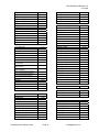
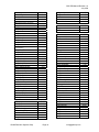
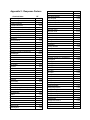
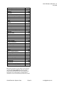
Operation & Maintenance Manual
GDS-PID
Photoionization Detector
Gas Sensor
For Detection of Organic & Inorganic Gases
Important: Read and understand contents prior to first
use. Improper use or operation could result in instrument
malfunction or serious injury.
© 2006 Global Detection Systems Corp.
All Rights Reserved
GDS PID Manual Revision 1.0
July 2006
This page intentionally left blank
Global Detection Systems Corp
Page 2
[email protected]
GDS PID Manual Revision 1.0
July 2006
Table of Contents
SECTION 1 – SAFETY INFORMATION
5
1.1
Safety Information – Read Before Installation & Applying Power
5
1.2
Contacting Global Detection Systems Corp.
5
SECTION 2 – PID SPECIFICATIONS
6
SECTION 2 - GENERAL DESCRIPTION
7
3.1
GDS Photoionization (PID) Gas Detector for Organic & Inorganic Gases
7
3.2
Features (Installed in GDS-48 Remote Sensor Housing)
7
3.3
Features (Installed with GASMAX II Gas Monitor)
7
3.4
Photoionization Detection Technology
8
SECTION 4 - OPERATION
9
4.1
Installation and Startup
9
4.2
Warm-up
10
4.3
Normal Operation
10
SECTION 5 - CALIBRATION
12
5.1
Calibration
12
5.2
Calibration with Known Target Gas
12
5.3
Response Factor
12
5.4
Calibration with Isobutylene
13
SECTION 6 – SENSOR MAINTENANCE
15
6.1
15
GDS-PID Maintenance
SECTION 7 – PARTS LIST & DRAWINGS
15
APPENDIX 1: IONIZATION POTENTIALS
16
APPENDIX 2: RESPONSE FACTORS
21
Global Detection Systems Corp
Page 3
[email protected]
GDS PID Manual Revision 1.0
July 2006
This page intentionally left blank
Global Detection Systems Corp
Page 4
[email protected]
GDS PID Manual Revision 1.0
July 2006
SECTION 1 – SAFETY INFORMATION
1.1
Safety Information – Read Before Installation & Applying Power
IMPORTANT
Users should have a detailed understanding of GDS-PID operating and maintenance instructions. Use the
GDS-PID only as specified in this manual or detection of gases and the resulting protection provided may be
impaired. Read the following WARNINGS prior to use.
WARNINGS
•
Do not paint the sensor assembly.
•
Do not use the GDS-PID if its enclosure is damaged or cracked or has missing components.
•
Make sure the cover and field wiring are securely in place before operation.
•
Periodically test for correct operation of the system’s alarm events by exposing the monitor / sensor
system to a targeted gas concentration above the High Alarm set point.
•
Do not expose the GDS-PID to electrical shock or continuous severe mechanical shock.
•
Protect the GDS-PID from dripping liquids and high power sprays.
•
Use only for applications described within this manual.
CAUTION: FOR SAFETY REASONS THIS EQUIPMENT MUST BE OPERATED AND SERVICED BY
QUALIFIED PERSONNEL ONLY. READ AND UNDERSTAND INSTRUCTION MANUAL COMPLETELY
BEFORE OPERATING OR SERVICING.
ATTENTION: POUR DES RAISONS DE SÉCURITÉ, CET ÉQUIPEMENT DOIT ÊTRE UTILISÉ,
ENTRETENU ET RÉPARÉ UNIQUEMENT PAR UN PERSONNEL QUALIFIÉ. ÉTUDIER LE MANUE
D’INSTRUCTIONS EN ENTIER AVANT D’UTILISER, D’ENTRETENIR OU DE RÉPARER
L’ÉQUIPEMENT.
1.2
Contacting Global Detection Systems Corp.
To contact Global Detection Systems Corp, please call 409-927-2980, FAX 409-927-4180 or visit us on the
web at www.gdscorp.com For sales information, send email to [email protected] or for technical support
email us at [email protected] Our headquarters are located at 2513 Hwy 6 in Santa Fe, Texas 77510.
Global Detection Systems Corp
Page 5
[email protected]
GDS PID Manual Revision 1.0
July 2006
SECTION 2 – PID SPECIFICATIONS
Model:
Available gases:
Detection Method:
Output (analog):
Linear Range:
Response Time:
Operating Temperature
Rating:
Operating Voltage:
Hazardous
Environment
Certification
Warranty:
Global Detection Systems Corp. PID Photoionization Detector for Organic &
Inorganic Compounds
Volatile Organic Compounds and other gases with an Ionization Potential (IP) of
10.6eV or less (See Appendix A)
Diffusion
Installed in GDS-48 Universal Sensor Head:
Bridge output similar to traditional catalytic bead sensor
Installed in GASMAX II Gas Monitor:
4-20 mA (Source type) max. 600 Ohm load at 24 VDC supply voltage
Low Range: 0-20 ppm (Isobutylene equivalent)
High Range: 0-2000 ppm (Isobutylene equivalent)
T90 < 20 Seconds (diffusion mode)
Remote installation using GDS-48 Universal Sensor:
0°C to +50°C
Local installation with GASMAX II Gas Monitor (Arctic Monitor option):
-40°C to +50°C
Installed in GDS-48 Universal Sensor Head:
3.3 to 5.0V DC measured at the detector head
Installed in GASMAX II Gas Monitor:
10-30 VDC measured at the detector head
Installed in GDS-48 Universal Sensor Head:
CSA Certified Class 1, Division 1, Groups B, C, D
Installed in GASMAX II Gas Monitor:
CSA Certified Class 1, Division 1 Groups B, C, D
Electronics (GASMAX II) – Two years from date of purchase
Sensor: (PID) – One year from date of purchase
Global Detection Systems Corp
Page 6
[email protected]
GDS PID Manual Revision 1.0
July 2006
SECTION 2 - GENERAL DESCRIPTION
3.1
GDS Photoionization (PID) Gas Detector for Organic & Inorganic Gases
The GDS-PID photoionization gas detector is a permanently-mounted microprocessor based smart sensor
that continuously monitors for a wide range of organic and inorganic gases. With an output similar to a
traditional catalytic bead combustible gas sensor, the GDS PID can be connected to a GDS Corp C1
Protector sixteen-channel controller, a GDS Corp C2 Protector two-channel controller, a single or dual
channel GASMAX II Gas Monitor, or other instrumentation device that supports a standard Whetstone
bridge input that can provide 3.5 - 5VDC excitation voltage. When used locally with the GASMAX II monitor,
a standard 4-20mA output, an isolated 4-20mA output, a MODBUS digital output and local alarm relay
contacts are available.
3.2
Features (Installed in GDS-48 Remote Sensor Housing)
• Output compatible with standard 3-wire catalytic bead bridge-type circuit (3.5 – 5 VDC excitation)
• Complete PID sensor, containing detector cell, photoionization lamp, lamp driver, amplifier and filter
• 10.6 eV lamp detects common VOCs while remaining insensitive to humidity, O2 or CO2 changes
• Replaceable lamp assembly
• High range (0 – 2000 ppm) and Low Range (0 – 20 ppm) versions available
• Can be installed Intrinsically Safe in hazardous areas (requires IS barrier) – contact factory for details
3.3
Features (Installed with GASMAX II Gas Monitor, C1 Controller or C2 Controller)
• All above features plus the following
• Smart Sensor records serial number, born-on date and other information (GASMAX only)
• Graphic alphanumeric display in engineering units with alarm LEDs
• Optional isolated 4-20mA output, MODBUS digital serial output
• Optional alarm relay contact closure (3 separate levels + Fault)
• Magnetic interface allows setup without declassifying hazardous area
• Second GASMAX channel supports simultaneous monitoring of toxic gas using electrochemical sensor
Global Detection Systems Corp
Page 7
[email protected]
GDS PID Manual Revision 1.0
July 2006
3.4
Photoionization Detection Technology
The Photoionization Detector (PID) detects a wide variety of organic compounds and some inorganic gases
in ambient air. Whether or not a compound can be detected by a PID depends on the lamp energy and the
energy required to remove an electron from the target compound molecule (its ionization potential). If the
lamp energy is greater than the compounds ionization potential, the PID will detect it.
Due to its sensitivity, a PID is not recommended for high concentrations of target gases. However, a PID
does not require oxygen to operate and so would be the detector of choice in conditions where O2 levels are
unpredictable. A PID can also react to a number of inorganic substances, including Ammonia, Carbon
Disulfide, Carbon Tetrachloride, Chloroform, Ethylamine, Formaldehyde and Hydrogen Sulfide.
A typical PID block diagram is shown below. Molecules of interest (1) are being exposed to high-energy
ultra-violet radiation (2), generated by the gas discharge lamp (3). Some percentage of these molecules are
ionized, i.e. converted into positively charged ions and negatively charged electrons:
To be ionized, the molecule M should have its Ionization Potential (IP) smaller than the energy of UV lamp
photons (E). As a rule, the bigger the difference is between E and IP, the bigger the detector’s response.
Both E and IP are usually measured in electron-volts (eV).
For the Ionization Potentials of various
chemicals, refer to Appendix 2.
The pair of electrodes (4, 5) is located in the ionization volume near the lamp window. One of them
(polarizing electrode, 4) is connected to the High Voltage DC source (7), the other (signal electrode, 5) is
attached to the amplifier (6) input. The electric field, created
by these two electrodes, forces both electrons and ions to drift
towards their respective electrode, by which they are being
collected. The resulting small current is being amplified by the
amplifier chip and then the output analog signal is recorded
and/or displayed in digital or analog format. The output signal
is proportional to the concentration of ionizable molecules in
detector’s chamber and thus serves as a measure of
concentration. Major air components (N2, O2, CO2) are not
ionized by typical lamp’s radiation and therefore do not
generate any detector’s response. For this reason, PID is very useful for detection of a wide range of VOCs
(Volatile Organic Compounds) in ambient air, down to the low-ppb concentrations, without interference from
air components.
Global Detection Systems Corp
Page 8
[email protected]
GDS PID Manual Revision 1.0
July 2006
SECTION 4 - OPERATION
4.1
Installation and Startup
Warning: The user shall be made aware that if the equipment is used in a manner not specified by the
manufacturer, the protection provided by the equipment may be impaired.
The first step in the installation process is to establish a mounting location for the GDS PID. Select a
location that is typical of the atmosphere to be monitored or close to the anticipated source of a target gas.
It is very important that the GDS PID be properly located to enable it to provide maximum protection. The
most effective number and placement of sensors vary depending on the conditions of the application. When
determining where to locate sensors the following factors should be considered.
•
What are the characteristics of the gas that is to be detected? Is it lighter or heavier than air? If it is
lighter than air the sensor should be placed above the potential gas leak. Place the sensor close to the
floor for gases that are heavier than air or for vapors resulting from flammable liquid spills. Note that air
currents can cause a gas that is heavier than air to rise. In addition, if the temperature of the gas is
hotter than ambient air or mixed with gases that are lighter than air, it could also rise.
•
How rapidly will the gas diffuse into the ambient air? Select a location for the sensor that is close to the
anticipated source of a gas leak.
•
Wind or ventilation characteristics of the immediate area must also be considered. Movement of air may
cause gas to accumulate more heavily in one area than in another. The detector should be placed in the
areas where the most concentrated accumulation of gas is anticipated. For outdoor applications with
strong wind conditions, it may require the sensors to be mounted closer together and on the down wind
side, to the anticipated area of a gas leak. Also take into consideration for indoor applications, the fact
that many ventilation systems do not operate continuously.
•
The sensor should be accessible for maintenance.
•
Excessive heat or vibration can cause premature failure of any electronic device and should be avoided
if possible.
•
Follow all national and local installation codes and practices.
Both the GDS-48 Universal Sensor housing and GASMAX II Gas Monitor provide a ¾” NPT threaded
connector for installation with conduit or shielded cable. Shielded cable is recommended. Wiring should
be installed in metal conduit with no other cabling in the same conduit.
Global Detection Systems Corp
Page 9
[email protected]
GDS PID Manual Revision 1.0
July 2006
4.2
Warm-up
The GDS PID gas detector is a very sensitive device, and if the sensor has been stored for a significant
amount of time, it may become contaminated with trace amounts of ambient detectable compounds. This in
turn may cause excessive drift of the background signal during warm-up. Therefore, it is highly
recommended to run the sensor for some period of time after prolonged storage, especially if it going to be
used for the low level applications. An overnight burn-in period should be sufficient in most cases. During
this time, the detector will clean itself and the baseline signal will drop and stabilize. If the sensor is used on
a daily basis, it should be allowed to stabilize for 10-20 minutes before use. If high accuracy is not important
(for example, in leak detection application) or in the case of measuring relatively high concentrations (> 100
ppm), this stabilization procedure can be skipped.
4.3
Normal Operation
The operation of any gas sensor should be checked periodically to ensure proper operation. When first
installed, the GDS PID should be challenged with a calibration gas (Isobutylene recommended) to make
certain that the detector and any associated alarm systems are functional. Periodically thereafter, the GDS
PID should be tested and/or recalibrated as necessary. Normally, initial calibration tests should be done at
least monthly, and may be done on a more extended basis once some experience with the sensor and
surrounding environment is obtained.
The GDS PID responds to a wide range of organic and inorganic molecules. To determine if a particular gas
generate a detector response, consult Appendix A and compare the Ionization Potential listed with the GDS
PID lamp energy rating (10.6 eV). For example, the GDS PID will detect Ammonia (IP = 10.2), whereas it
will not detect Acetylene (IP = 11.41). In general, the lower the IP value, the more sensitive the reading and
the lower the Minimum Detectible Quantity (MDQ).
Depending on the IP of the compound and some other properties, the sensor’s sensitivity varies significantly
from one compound to another. If, for example, the sensor generates double the response to some
compound as to Isobutylene, one should expect two times better MDQ, and vice versa – compounds to
which the sensor has lesser sensitivity, it will have proportionally higher MDQ.
The high range sensor linear range is at least 0 to 2000 ppm of Isobutylene, based on a maximum of 20%
non-linearity. The calibration point in this case is 100 ppm. However, the sensor’s signal continues to
increase uniformly as concentration increases all the way to 5000 ppm. As a result, the sensor can be used
beyond the normal linear range for certain applications, including alarm triggering at high concentrations
Global Detection Systems Corp
Page 10
[email protected]
GDS PID Manual Revision 1.0
July 2006
(4000 ppm, for example). In this case the sensor must be calibrated at this concentration with actual gas
samples.
Another way to extend the linear range of the GDS PID is to use software linearization. Since the sensor has
reproducible characteristics from unit to unit, an appropriate software algorithm can be applied for this
purpose. The GASMAX II provides an easy way to enter a specific ten-point piecewise approximation
response curve.
The overall linearity of the sensor may vary slightly, depending on the target compound. As a rule, if the
GDS PID is very sensitive to a given compound, the available linear range will be relatively narrow, and vice
versa. Therefore, if some application requires high accuracy, the linearity characteristic of the sensor should
be experimentally measured for this particular application’s target compound.
A sample’s balance gas affects the sensor’s response to the target gas, mainly as a result of the difference
in UV transparency for different balance gases. In a less UV-transparent environment (ex: O2, CH4) the
GDS-PID will have a lower response to a target gas than it would in a more UV-transparent environment
(ex: N2, H2). Therefore, for best accuracy calibration should be done in an environment that is as close as
possible to the actual operating conditions, especially with respect to humidity and the presence of low
levels of non-VOC compounds.
Global Detection Systems Corp
Page 11
[email protected]
GDS PID Manual Revision 1.0
July 2006
SECTION 5 - CALIBRATION
5.1
Calibration
It is important to understand that the GDS PID is a broadband detector capable of responding to a wide
range of organic and inorganic substances, and will respond to any individual gas or combination of gases
with IP values less than the lamp UV energy level (10.6 eV).
In general, if an actual sample of the expected target compound (between 40% and 80% of the desired full
scale value) is available, it is recommended that the GDS PID be calibrated using the target gas in place of
Isobutylene. This technique will ensure maximum accuracy.
After installation, allow the GDS-PID to stabilize for a period of 8 hours or more, preferably overnight. After
stabilization, calibrate the unit as described below. During the first several weeks of operation, periodically
calibrate the unit to ensure there are no localized sources of contamination that may block the sensors
window. It is recommended that the period between calibrations be no longer than 30 days.
5.2
Calibration with Known Target Gas
If a known concentration sample of the desired target gas is available, the GDS PID sensor can be
calibrated like any typical sensor. In the case of a GDS PID installed remotely using a GDS-48, the
calibration procedure associated with the assigned controller should be used. For example, the C1 Protector
sixteen-channel controller provides an option for “Local Calibration” that allows the necessary zero and span
adjustments to be performed. See the C1 Protector Controller manual for further details.
If the GDS PID is connected to a GASMAX II gas monitor, the standard built-in GASMAX II calibration
should be used. See the GASMAX family manual for further details on sensor calibration procedures.
IMPORTANT: Calibrating the GDS-PID for a specific gas does not make it selective to that gas. A PID is a
wideband detector and will always indicate the total concentration of ionizable VOCs present in the ambient
air sample.
5.3
Response Factor
In many cases, calibrating the detector with actual target gas is impractical due to toxicity, cost or availability
constraints. In these situations, the GDS PID sensor can be calibrated using Isobutylene in place of the
target gas and a Response Factor can be applied to the output. The Response Factor is unique for each
desired target gas (see Appendix B for a list of GDS-PID Response Factors).
Global Detection Systems Corp
Page 12
[email protected]
GDS PID Manual Revision 1.0
July 2006
The Response Factor measures the ratio between the sensitivity to a standard gas (isobutylene) and that of
a target compound. For example, if the GDS PID low range sensor has a typical sensitivity of 1mV/ppm for
Isobutylene and 2 mV/ppm for Benzene that means that Benzene Response Factor is equal to ~0.5. The
Response Factor is calculated by dividing the actual concentration of a compound introduced into the
sensor by the measured detector response:
Response Factor =
Actual Concentration
Measured Response
In general, if the Response Factor is less than 1.0, the GDS PID is more sensitive to the target compound
that it is to Isobutylene; if greater than 1.0, the GDS PID is less sensitive to the target compound than it is to
Isobutylene.
5.4
Calibration with Isobutylene
When the desired target gas is unavailable or excessively dangerous, the GDS-PID can be calibrated using
isobutylene and the output value adjusted to determine the actual target gas concentration.
Manual Conversion: One way to calculate the actual concentration of a target gas is to calibrate the
GDSPID using Isobutylene, apply the target gas and manually multiply the detector reading by the target
gas Response Factor. This technique is useful if more than one type of gas may be present, or if several
different gases may be introduced into the detector, and it is not practical to recalibrate for a specific gas.
For example, if a sample of Ammonia (RF = 9.4) in air is applied to a GDS-PID / GASMAX II (Low Range
sensor, calibrated for 0-20ppm Isobutylene) monitor and the GASMAX II reads 10ppm, the actual Ammonia
concentration would be 94 ppm.
10ppm (Reading)
9.4 (Ammonia RF) = 94 ppm Ammonia
Like any photoionization detector, the GDS PID will respond to many different compounds simultaneously. If
a single gas is present, a single Response Factor can be used to determine the final reading. In the event
that the gas present is a mixture of several compounds, each having a different Response Factor, the
process to calculate the actual concentrations is more difficult. In general, Response Factors for various
mixtures of gases are not available. However, if the composition of the mixture is known with some
accuracy, a corrected Response Factor can be obtained by adding weighted fractions of the different
Response Factors of the mixture components. For example, if the mixture contains 60% Benzene and 40%
Global Detection Systems Corp
Page 13
[email protected]
GDS PID Manual Revision 1.0
July 2006
Toluene, multiply the Benzene factor by 0.6, the Toluene factor by 0.4 and add the result to obtain the new
factor.
Direct readout in PPM: An alternative procedure to calibrate the GDS PID can provide a direct readout on
the GASMAX II monitor for a specific compound. NOTE: This procedure does not make the GDS-PID
selective to the target compound.
RF = Response Factor for specific compound
CG = PPM value of isobutylene calibration gas
LOW RANGE SENSOR
1. Set the GASMAX II SPAN value [20 * RF]
2. Set the GASMAX II CAL SPAN value to [CG * RF]
3. Make sure no VOCs are present in the ambient air surrounding the GASMAX II. If unable to
guarantee no VOCs present, apply a steady flow of 0.5 L/min of ZERO AIR.
4. Perform a ZERO CALIBRATION on the GASMAX II gas monitor.
5. Apply a steady flow of 0.5 L/min of isobutylene calibration gas (8 - 16 ppm recommended)
6. Perform a SPAN CALIBRATION on the GASMAX II gas monitor.
7. The GASMAX II will now display the target gas concentration in PPM.
HIGH RANGE SENSOR
8. Set the GASMAX II SPAN value [2000 * RF]
9. Set the GASMAX II CAL SPAN value to [CG * RF]
10. Make sure no VOCs are present in the ambient air surrounding the GASMAX II. If unable to
guarantee no VOCs present, apply a steady flow of 0.5 L/min of ZERO AIR.
11. Perform a ZERO CALIBRATION on the GASMAX II gas monitor.
12. Apply a steady flow of 0.5 L/min of isobutylene calibration gas (800 - 1600 ppm recommended)
13. Perform a SPAN CALIBRATION on the GASMAX II gas monitor.
14. The GASMAX II will now display the target gas concentration in PPM.
Note: Response factor values are approximate and are only given as a general guide to the response
which may be expected from other gases. For accurate readings, it is always better to calibrate the unit with
the actual target gas whenever possible.
Global Detection Systems Corp
Page 14
[email protected]
GDS PID Manual Revision 1.0
July 2006
SECTION 6 – SENSOR MAINTENANCE
6.1
GDS-PID Maintenance
The GDS-PID sensor is a highly reliable, self-contained photoionization detector that requires very little
maintenance other than periodic calibration and lamp replacement. There are no user-serviceable parts.
Cleaning – During the course of normal operation, contaminants in the ambient air can cause a reduction in
sensitivity due to a build-up of film on the sensor’s UV window. Periodic calibration will compensate for this
effect. In the event that the sensor’s sensitivity drops excessively, the sensor should be returned to the
factory for cleaning.
Lamp Replacement – The sensor’s life span is determined by the life of the UV lamp, typically > 5000
hours of continuous operation. Over the lamp’s lifetime, the output will gradually decline, but the effect will
be insignificant until well after 5000 hours of operation. Normal re-calibration will compensate for this effect.
The lamp is replaceable. Contact GDS Corp for more information regarding PID sensor refurbishment
options.
SECTION 7 – PARTS LIST & DRAWINGS
Part Number Description
10-9060
10-9061
10-906XR
10-0247
10-0198
10-0205
10-0187
1000-0078
Global Detection Systems Corp
Page 15
Photoionization Detector for VOC (0-2000ppm)
Photoionization Detector for VOC (0-20ppm)
PID Sensor Refurbishment
Remote Stainless Steel Sensor Head w/ Cover
Sensor splash guard
Sensor flow cell for process monitoring
Sensor replacement tool
Large black magnet for GASMAX II
[email protected]
Appendix 1: Ionization
Potentials
Chemical Name
A
IP (eV)
2-Amino pyridine
Acetaldehyde
Acetamide
Acetic acid
Acetic anhydride
Acetone
Acetonitrile
Acetophenone
Acetyl bromide
Acetyl chloride
Acetylene
Acrolein
Acrylamide
Acrylonitrile
Allyl alcohol
Allyl chloride
Ammonia
Aniline
Anisidine
Anisole
Arsine
B
8
10.21
9.77
10.69
10
9.69
12.2
9.27
10.55
11.02
11.41
10.1
9.5
10.91
9.67
9.9
10.2
7.7
7.44
8.22
9.89
1,3-Butadiene (butadiene)
1-Bromo-2-chloroethane
1-Bromo-2-methylpropane
1-Bromo-4-fluorobenzene
1-Bromobutane
1-Bromopentane
1-Bromopropane
1-Bromopropene
1-Butanethiol
1-Butene
1-Butyne
2,3-Butadione
2-Bromo-2-methylpropane
2-Bromobutane
2-Bromopropane
2-Bromothiophene
2-Butanone (MEK)
3-Bromopropene
3-Butene nitrile
Benzaldehyde
Benzene
9.07
10.63
10.09
8.99
10.13
10.1
10.18
9.3
9.14
9.58
10.18
9.23
9.89
9.98
10.08
8.63
9.54
9.7
10.39
9.53
9.25
Benzenethiol
Benzonitrile
Benzotrifluoride
Biphenyl
Boron oxide
Boron trifluoride
Bromine
Bromobenzene
Bromochloromethane
Bromoform
Butane
Butyl mercaptan
cis-2-Butene
m-Bromotoluene
n-Butyl acetate
n-Butyl alcohol
n-Butyl amine
n-Butyl benzene
n-Butyl formate
n-Butyraldehyde
n-Butyric acid
n-Butyronitrile
o-Bromotoluene
p-Bromotoluene
p-tert-Butyltoluene
s-Butyl amine
s-Butyl benzene
sec-Butyl acetate
t-Butyl amine
t-Butyl benzene
trans-2-Butene
C
8.33
9.71
9.68
8.27
13.5
15.56
10.54
8.98
10.77
10.48
10.63
9.15
9.13
8.81
10.01
10.04
8.71
8.69
10.5
9.86
10.16
11.67
8.79
8.67
8.28
8.7
8.68
9.91
8.64
8.68
9.13
1-Chloro-2-methylpropane
1-Chloro-3-fluorobenzene
1-Chlorobutane
1-Chloropropane
2-Chloro-2-methylpropane
2-Chlorobutane
2-Chloropropane
2-Chlorothiophene
3-Chloropropene
Camphor
Carbon dioxide
Carbon disulfide
Carbon monoxide
Carbon tetrachloride
Chlorine
Chlorine dioxide
Chlorine trifluoride
Chloroacetaldehyde
10.66
9.21
10.67
10.82
10.61
10.65
10.78
8.68
10.04
8.76
13.79
10.07
14.01
11.47
11.48
10.36
12.65
10.61
GDS PID Manual Revision 1.0
July 2006
á -Chloroacetophenone
Chlorobenzene
Chlorobromomethane
Chlorofluoromethane (Freon
22)
Chloroform
Chlorotrifluoromethane (Freon 13)
Chrysene
Cresol
Crotonaldehyde
Cumene (isopropyl benzene)
Cyanogen
Cyclohexane
Cyclohexanol
Cyclohexanone
Cyclohexene
Cyclo-octatetraene
Cyclopentadiene
Cyclopentane
Cyclopentanone
Cyclopentene
Cyclopropane
m-Chlorotoluene
o-Chlorotoluene
p-Chlorotoluene
D
9.44
9.07
10.77
12.45
1,1-Dibromoethane
1,1-Dichloroethane
1,1-Dimethoxyethane
1,1-Dimethylhydrazine
1,2-Dibromoethene
10.19
11.12
9.65
7.28
9.45
12.2
1,2-Dichloro-1,1,2,2tetrafluoroethane (Freon 114)
1,2-Dichloroethane
1,2-Dichloropropane
1,3-Dibromopropane
1,3-Dichloropropane
2,2-Dimethyl butane
2,2-Dimethyl propane
2,3-Dichloropropene
2,3-Dimethyl butane
3,3-Dimethyl butanone
cis-Dichloroethene
Decaborane
Diazomethane
Diborane
Dibromochloromethane
Dibromodifluoromethane
Dibromomethane
Dibutylamine
Global Detection Systems Corp
11.37
12.91
7.59
8.14
9.73
8.75
13.8
9.8
9.75
9.14
8.95
7.99
8.56
10.53
9.26
9.01
10.06
8.83
8.83
8.7
11.12
10.87
10.07
10.85
10.06
10.35
9.82
10.02
9.17
9.65
9.88
9
12
10.59
11.07
10.49
7.69
Page 17
Dichlorodifluoromethane (Freon 12)
Dichlorofluoromethane
Dichloromethane
Diethoxymethane
Diethyl amine
Diethyl ether
Diethyl ketone
Diethyl sulfide
Diethyl sulfite
Difluorodibromomethane
Dihydropyran
Diiodomethane
Diisopropylamine
Dimethoxymethane (methylal)
Dimethyl amine
Dimethyl ether
Dimethyl sulfide
Dimethylaniline
Dimethylformamide
Dimethylphthalate
Dinitrobenzene
Dioxane
Diphenyl
Dipropyl amine
Dipropyl sulfide
Durene
m-Dichlorobenzene
N,N-Diethyl acetamide
N,N-Diethyl formamide
N,N-Dimethyl acetamide
N,N-Dimethyl formamide
o-Dichlorobenzene
p-Dichlorobenzene
p-Dioxane
trans-Dichloroethene
E
Epichlorohydrin
Ethane
Ethanethiol (ethyl mercaptan)
Ethanolamine
Ethene
Ethyl acetate
Ethyl alcohol
Ethyl amine
Ethyl benzene
Ethyl bromide
Ethyl chloride (chloroethane)
Ethyl disulfide
Ethylene
Ethyl ether
[email protected]
12.31
12.39
11.35
9.7
8.01
9.53
9.32
8.43
9.68
11.07
8.34
9.34
7.73
10
8.24
10
8.69
7.13
9.18
9.64
10.71
9.19
7.95
7.84
8.3
8.03
9.12
8.6
8.89
8.81
9.12
9.06
8.95
9.13
9.66
10.2
11.65
9.29
8.96
10.52
10.11
10.48
8.86
8.76
10.29
10.98
8.27
10.5
9.51
GDS PID Manual Revision 1.0
July 2006
Ethyl formate
Ethyl iodide
Ethyl isothiocyanate
Ethyl mercaptan
Ethyl methyl sulfide
Ethyl nitrate
Ethyl propionate
Ethyl thiocyanate
Ethylene chlorohydrin
Ethylene diamine
Ethylene dibromide
Ethylene dichloride
Ethylene oxide
Ethylenelmine
Ethynylbenzene
F
10.61
9.33
9.14
9.29
8.55
11.22
10
9.89
10.52
8.6
10.37
11.05
10.57
9.2
8.82
2-Furaldehyde
Fluorine
Fluorobenzene
Formaldehyde
Formamide
Formic acid
9.21
15.7
9.2
10.87
10.25
11.05
11.77
11.3
Freon 11 (trichlorofluoromethane)
Freon 112 (1,1,2,2-tetrachloro-1,2difluoroethane)
Freon 113 (1,1,2-trichloro-1,2,2trifluororethane)
Freon 114 (1,2-dichloro-1,1,2,2tetrafluoroethane)
Freon 12 (dichlorodifluoromethane)
Freon 13 (chlorotrifluoromethane)
Freon 22 (chlorofluoromethane)
Furan
Furfural
m-Fluorotoluene
o-Fluorophenol
o-Fluorotoluene
p-Fluorotoluene
H
1-Hexene
2-Heptanone
2-Hexanone
Heptane
Hexachloroethane
Hexane
Hydrazine
Hydrogen
Hydrogen bromide
Hydrogen chloride
Hydrogen cyanide
Hydrogen fluoride
Global Detection Systems Corp
11.78
12.2
12.31
12.91
12.45
8.89
9.21
8.92
8.66
8.92
8.79
9.46
9.33
9.35
10.08
11.1
10.18
8.1
15.43
11.62
12.74
13.91
15.77
Page 18
Hydrogen iodide
Hydrogen selenide
Hydrogen sulfide
Hydrogen telluride
Hydroquinone
I
10.38
9.88
10.46
9.14
7.95
1-Iodo-2-methylpropane
1-Iodobutane
1-Iodopentane
1-Iodopropane
2-Iodobutane
2-Iodopropane
Iodine
Iodobenzene
Isobutane (Isobutylene)
Isobutyl acetate
Isobutyl alcohol
Isobutyl amine
Isobutyl formate
Isobutyraldehyde
Isobutyric acid
Isopentane
Isophorone
Isoprene
Isopropyl acetate
Isopropyl alcohol
Isopropyl amine
Isopropyl benzene
Isopropyl ether
Isovaleraldehyde
m-Iodotoluene
o-Iodotoluene
p-Iodotoluene
K
9.18
9.21
9.19
9.26
9.09
9.17
9.28
8.73
9.4
9.97
10.12
8.7
10.46
9.74
10.02
10.32
9.07
8.85
9.99
10.16
8.72
8.69
9.2
9.71
8.61
8.62
8.5
Ketene
L
9.61
2,3-Lutidine
2,4-Lutidine
2,6-Lutidine
M
8.85
8.85
8.85
2-Methyl furan
2-Methyl naphthalene
1-Methyl naphthalene
2-Methyl propene
2-Methyl-1-butene
2-Methylpentane
3-Methyl-1-butene
3-Methyl-2-butene
3-Methylpentane
[email protected]
8.39
7.96
7.96
9.23
9.12
10.12
9.51
8.67
10.08
GDS PID Manual Revision 1.0
July 2006
4-Methylcyclohexene
Maleic anhydride
Mesityl oxide
Mesitylene
Methane
Methanethiol (methyl mercaptan)
Methyl acetate
Methyl acetylene
Methyl acrylate
Methyl alcohol
Methyl amine
Methyl bromide
Methyl butyl ketone
Methyl butyrate
Methyl cellosolve
Methyl chloride
Methyl chloroform (1,1,1trichloroethane)
Methyl disulfide
Methyl ethyl ketone
Methyl formate
Methyl iodide
Methyl isobutyl ketone
Methyl isobutyrate
Methyl isocyanate
Methyl isopropyl ketone
Methyl isothiocyanate
Methyl mercaptan
Methyl methacrylate
Methyl propionate
Methyl propyl ketone
á -Methyl styrene
Methyl thiocyanate
Methylal (dimethoxymethane)
Methylcyclohexane
Methylene chloride
Methyl-n-amyl ketone
Monomethyl aniline
Monomethyl hydrazine
Morpholine
n-Methyl acetamide
N
1-Nitropropane
2-Nitropropane
Naphthalene
Nickel carbonyl
Nitric oxide, (NO)
Nitrobenzene
Nitroethane
Nitrogen
Global Detection Systems Corp
8.91
10.8
9.08
8.4
12.98
9.44
10.27
10.37
9.9
10.85
8.97
10.54
9.34
10.07
9.6
11.28
11
8.46
9.53
10.82
9.54
9.3
9.98
10.67
9.32
9.25
9.44
9.7
10.15
9.39
8.35
10.07
10
9.85
11.32
9.3
7.32
7.67
8.2
8.9
10.88
10.71
8.12
8.27
9.25
9.92
10.88
15.58
Page 19
Nitrogen dioxide
Nitrogen trifluoride
Nitromethane
Nitrotoluene
p-Nitrochloro benzene
O
9.78
12.97
11.08
9.45
9.96
Octane
Oxygen
Ozone
P
9.82
12.08
12.08
1-Pentene
1-Propanethiol
2,4-Pentanedione
2-Pentanone
2-Picoline
3-Picoline
4-Picoline
n-Propyl nitrate
Pentaborane
Pentane
Perchloroethylene
Pheneloic
Phenol
Phenyl ether (diphenyl oxide)
Phenyl hydrazine
Phenyl isocyanate
Phenyl isothiocyanate
Phenylene diamine
Phosgene
Phosphine
Phosphorus trichloride
Phthalic anhydride
Propane
Propargyl alcohol
Propiolactone
Propionaldehyde
Propionic acid
Propionitrile
Propyl acetate
Propyl alcohol
Propyl amine
Propyl benzene
Propyl ether
Propyl formate
Propylene
Propylene dichloride
Propylene imine
Propylene oxide
Propyne
9.5
9.2
8.87
9.38
9.02
9.02
9.04
11.07
10.4
10.35
9.32
8.18
8.5
8.82
7.64
8.77
8.52
6.89
11.77
9.87
9.91
10
11.07
10.51
9.7
9.98
10.24
11.84
10.04
10.2
8.78
8.72
9.27
10.54
9.73
10.87
9
10.22
10.36
[email protected]
GDS PID Manual Revision 1.0
July 2006
Pyridine
Pyrrole
Q
9.32
8.2
Quinone
S
10.04
Stibine
Styrene
Sulfur dioxide
Sulfur hexafluoride
Sulfur monochloride
Sulfuryl fluoride
T
9.51
8.47
12.3
15.33
9.66
13
o-Terphenyls
1,1,2,2-Tetrachloro-1,2difluoroethane (Freon 112)
1,1,1-Trichloroethane
1,1,2-Trichloro-1,2,2-trifluoroethane
(Freon 113)
2,2,4-Trimethyl pentane
o-Toluidine
Tetrachloroethane
Tetrachloroethene
Tetrachloromethane
Tetrahydrofuran
Tetrahydropyran
Thiolacetic acid
Thiophene
Toluene
Tribromoethene
Tribromofluoromethane
Tribromomethane
Trichloroethene
Trichloroethylene
Trichlorofluoromethane (Freon 11)
Trichloromethane
Triethylamine
Trifluoromonobromo-methane
Trimethyl amine
Tripropyl amine
V
o-Vinyl toluene
Valeraldehyde
Valeric acid
Vinyl acetate
Vinyl bromide
Vinyl chloride
Vinyl methyl ether
W
Water 1
X
Global Detection Systems Corp
2,4-Xylidine
m-Xylene
o-Xylene
p-Xylene
7.65
8.56
8.56
8.45
7.78
11.3
11
11.78
9.86
7.44
11.62
9.32
11.47
9.54
9.25
10
8.86
8.82
9.27
10.67
10.51
9.45
9.47
11.77
11.42
7.5
11.4
7.82
7.23
8.2
9.82
10.12
9.19
9.8
10
8.93
2.59
Page 20
[email protected]
Appendix 2: Response Factors
Chemical Name
1,2,3-trimethylbenzene
1,2,4-trimethylbenzene
1,2-dibromoethane
1,2-dichlorobenzene
1,2-dichloroethane (11.7 lamp)
1,3,5-trimethylbenzene
1,4-dioxane
1-butanol
1-methoxy-2-propanol
1-propanol
2-butoxyethanol
2-methoxyethanol
2-pentanone
2-picoline
3-picoline
4-hydroxy-4-methyl-2-pentanone
acetaldehyde
acetic acid
acetone
acetophenone
acrolein
allyl alcohol
ammonia
amylacetate
arsine
benzene
bromoform
bromomethane
butadiene
butyl acetate
carbon disulfide
chlorobenzene
cumene (isopropylbenzene)
cyclohexane
cyclohexanone
decane
diethylamine
dimethoxymethane
dimethyl disulfide
diesel fuel #1
diesel fuel #2
epichlorhydrin
RF
0.49
0.43
11.70
0.50
0.50
0.34
1.40
3.40
1.40
5.70
1.30
2.50
0.78
0.57
0.90
0.55
10.80
11.00
1.20
0.59
3.90
2.50
9.40
3.50
2.60
0.53
2.30
1.80
0.69
2.40
1.20
0.40
0.54
1.50
0.82
1.60
1.00
11.30
0.30
0.90
0.75
7.60
ethanol
ethyl acetate
ethyl acetoacetate
ethyl acrylate
ethyl ether (diethyl ether)
ethyl mercaptan
ethylbenzene
ethylene
ethylene glycol
ethylene oxide
gasoline
heptane
hydrazine
hydrogen sulfide
isoamyl acetate
isobutanol
isobutyl acetate
isobutylene
isooctane
isopentane
isophorone
isoprene (2-methyl-1,3-butadiene)
isopropanol
isopropyl acetate
isopropyl ether
isopropylamine
Jet A fuel
JP-5 fuel
JP-8 fuel
mesityl oxide
methanol (11.7 lamp)
methyl acetate
methyl acetoacetate
methyl acrylate
methyl benzoate
methyl ethyl ketone
methyl isobutyl ketone
methyl mercaptan
methyl methacrylate
methyl tert-butyl ether
methylamine
methylbenzil alcohol
methylene chloride (11.7 lamp)
m-xylene
naphtalene
10.00
4.20
0.90
2.30
1.20
0.60
0.51
10.10
15.70
19.50
1.10
2.50
2.60
3.20
1.80
4.70
2.60
1.00
1.30
8.00
0.74
0.60
5.60
2.60
0.80
0.90
0.40
0.48
0.48
0.47
2.50
7.00
1.10
3.40
0.93
0.90
1.10
0.60
1.50
0.86
1.20
0.80
0.85
0.53
0.37
GDS PID Manual Revision 1.0
July 2006
n,n-dimethylacetamide
n,n-dimethylformamide
n-hexane
nitric oxide
n-nonane
nitrogen dioxide (11.7 lamp)
n-pentane
n-propyl acetate
octane
o-xylene
phenol
phosphine
pinene, alpha
pinene, beta
propionaldehyde (propanal)
propylene
propylene oxide
p-xylene
pyridine
quinoline
styrene
tert-butyl alcohol
tert-butyl mercaptan
tert-butylamine
tetrachloroethylene
tetrahydrofuran
thiophene
toluene
trans-1,2-Dichloroethene
trichloroethylene
trimethylamine
turpentine - crude sulfite
turpentine - pure gum
vinyl acetate
vinyl bromide
vinyl chloride
vinylcyclohexane (VCH)
vinylidene chloride (1,1-DCE)
0.73
0.80
4.50
7.20
1.60
10.00
9.70
3.10
2.20
0.54
1.00
2.80
0.40
0.40
14.80
1.30
6.50
0.50
0.79
0.72
0.40
3.40
0.55
0.71
0.56
1.60
0.47
0.53
0.45
0.50
0.83
1.00
0.45
1.30
0.40
1.80
0.54
0.80
Note: Data extracted from industry literature; actual data has
not been independently validated by GDS Corp. Response
factor values are approximate and are only given as a
general guide to the response which may be expected from
other gases. For accurate readings, it is always better to
calibrate the unit with the actual target gas whenever possible.
Global Detection Systems Corp
Page 22
[email protected]