1
(6627+(5:,6(63(&,),('
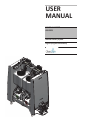
USER
MANUAL
MODEL NUMBER:
ALX-RDS
Remote Delivery System
English (Original Instructions)
35235,(7$5<$1'&21),'(17,$/
$/;0'60$1;
127,1&/8'('
6+2:1)25
,//8675$7,21
385326(621/<
USER MANUAL: ALX-RDS - Remote Delivery System
READ ALL INSTRUCTIONS BEFORE OPERATING EQUIPMENT
Table of Contents
Installation Instructions.......................................................................................................................................... 4
Tower................................................................................................................................................................................ 4
Control Box....................................................................................................................................................................... 4
Pump Controllers Board................................................................................................................................................... 5
Pump Inlet Manifold......................................................................................................................................................... 6
Air and Water Supply........................................................................................................................................................ 7
Destination Valves............................................................................................................................................................ 8
Setup Instructions.................................................................................................................................................. 9
General Settings................................................................................................................................................................ 9
Sleep Function.................................................................................................................................................................. 11
Site Info............................................................................................................................................................................. 12
RFID Association.............................................................................................................................................................. 13
Pump Controller Settings.................................................................................................................................................. 15
Destination Valve Settings................................................................................................................................................ 18
Manifold Settings.............................................................................................................................................................. 20
Priming Pumps.................................................................................................................................................................. 22
Calibrating the Scale......................................................................................................................................................... 23
Pump Calibration.............................................................................................................................................................. 24
Post-Dispense Water Flush............................................................................................................................................... 26
Operation Instructions............................................................................................................................................ 27
Dispensing........................................................................................................................................................................ 27
Syncing............................................................................................................................................................................. 30
Manual Water Flush.......................................................................................................................................................... 31
Maintenance Instructions....................................................................................................................................... 32
Scale Maintenance............................................................................................................................................................ 32
Standard & Event Logs..................................................................................................................................................... 34
Troubleshooting..................................................................................................................................................... 35
Validation Errors............................................................................................................................................................... 35
Dispense Errors................................................................................................................................................................. 40
Diagrams................................................................................................................................................................ 42
Piping and Instrumentation............................................................................................................................................... 42
Example System Layout................................................................................................................................................... 44
Dimensions Diagram........................................................................................................................................................ 45
Exploded Views/BOMs........................................................................................................................................... 46
Model ALX-RDS | Exploded View.................................................................................................................................. 46
Model ALX-RDS | BOM.................................................................................................................................................. 48
Model ALX-RDS-MAN-5................................................................................................................................................ 49
Model ALX-RDS-DEST-5 | Parts Callout........................................................................................................................ 50
Model ALX-RDS-DEST-5 | BOM.................................................................................................................................... 51
Model M1471 | Tank Assembly........................................................................................................................................ 52
Models M1489 & M1492 | Water & Air Regulators......................................................................................................... 53
Printable Instructions............................................................................................................................................. 54
Dispensing Instructions (English)..................................................................................................................................... 54
Dispensing Instructions (Spanish).................................................................................................................................... 56
Manually Emptying Tanks................................................................................................................................................ 58
USER MANUAL (MODEL: ALX-RDS) Page 2 of 58
11/01/2014
USER MANUAL: ALX-RDS - Remote Delivery System
READ ALL INSTRUCTIONS BEFORE OPERATING EQUIPMENT
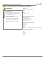
WARNING
Avoid Personal Injury
1. Avoid contact of cleaning agent with skin and
eyes. If contact occurs, see MSDS sheet for
further first aid measures.
2. Follow safety instructions of chemical
manufacturer (MSDS).
3. Always follow plant and OSHA guidelines
about the use of hygiene equipment.
4. Disconnect power before servicing unit.
Specifications
Frame..............1/2 HDPE Plastic
Width..............59”
Depth..............30”
Height.............51”
Water Connection Requirements
Cold Potable Water
35 PSI Minimum Pressure
60 PSI Maximum Pressure
5 GPM Connection
Electrical Connection Requirements
110 Volts AC
Single Phase
60 Hz
5 Amps
24 VDC - Control Voltage (Unit has internal power supply)
Acceptable Chemical Products
Acids
Caustics
Sanitizers
Chlorine
USER MANUAL (MODEL: ALX-RDS) Page 3 of 58
11/01/2014
USER MANUAL: ALX-RDS - Remote Delivery System
READ ALL INSTRUCTIONS BEFORE OPERATING EQUIPMENT
Installation Instructions
Tower
Set unit in desired location.
Aspects to consider when deciding on placement:
• Room for entering and exiting.
• Emergency exit paths.
• Space to access control box.
• Connections for water, air, and chemical lines.
Once the unit has been positioned correctly, level the unit
using the adjustable feet.
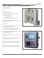
Control Box
Aspects to consider when deciding on placement:
• Distance to electrical connection.
• Cell signal strength (for the 3G router inside box)
• Distance from tower and pump controllers.
Attach the included mounting feet to the back of control
box with a phillips screwdriver.
Securely mount control box to wall, then plug into 115 volt
wall outlet.
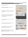
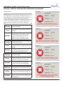
Open the box and look for 3 green lights on the router to
turn on - signaling there is full cell service.
If there are only 2 green lights and 1 orange light, the cell
box has low signal in the building, but still has internet
access.
Red lights show that the router has no service. Move the
box until an area with decent cellular service is found.
USER MANUAL (MODEL: ALX-RDS) Page 4 of 58
11/01/2014
USER MANUAL: ALX-RDS - Remote Delivery System
READ ALL INSTRUCTIONS BEFORE OPERATING EQUIPMENT
Pump Controllers Board
Air In from
Air Supply
The pump controllers are comprised of a circuit board and
solenoid to control air flow to each air operated double
diaphragm pump.
When a pump controller is turned on, the solenoid will
open and send air out to its corresponding AODD pump,
which will send chemical through the lines into the 10
gallon tanks mounted on the ALX-RDS.
Place pump controller board(s) in desired location.
Aspects to consider when deciding on placement:
• Number of pump controllers.
• Distance between the pumps and their pump
controllers.
• Quantity of hose and tubing available to make
connections.
Securely mount the board(s) to wall.
The pump controllers come pre-daisychained with their
CAN lines & 3/8” air lines. Use the provided 5m CAN cable
to connect multiple pump controller boards together if the
system comes with more than one board.
Connect the end of the CAN line on the pump controller
board to the CAN cable on the control box.
String 3/8” airlines from the “Air Out” connection on the
pump controllers to each corresponding pump to finish
installation.
Turn the control box on by pulling out on the red E-stop
mounted on the right side of the box, then check for a
green light on each pump controller, signaling power.
NOTE: The pumps require clean, dry air for proper
operation. The customer is responsible for installing an
air regulator before the pump controllers to ensure
correct operation of the solenoids. Do not use lubricated
air with this system.
USER MANUAL (MODEL: ALX-RDS) Page 5 of 58
11/01/2014
USER MANUAL: ALX-RDS - Remote Delivery System
READ ALL INSTRUCTIONS BEFORE OPERATING EQUIPMENT
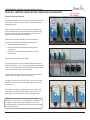
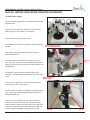
Pump Inlet Manifold
The 10 gallon tanks will already have the water lines from
the water supply running into the top of them for the tank
rinse and manifold flush, so the only hoses that need to be
connected are the chemical lines from the pumps.
Connect the outgoing hose from the pump output onto
the check valves on the Pump Inlet Manifold, using a hose
clamp on each hose.
Make sure the hose is all the way on the hosebarb before
tightening the hose clamp.
Make sure acids run into one manifold and caustics run
into the opposite one.
Once all of the chemical lines have been run, the Air and
Water supply can be setup.
USER MANUAL (MODEL: ALX-RDS) Page 6 of 58
11/01/2014
USER MANUAL: ALX-RDS - Remote Delivery System
READ ALL INSTRUCTIONS BEFORE OPERATING EQUIPMENT
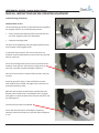
Air and Water Supply
The Air and Water regulators are mounted behind the two
10-gallon tanks.
Connect 1/2” tubing for the water line from the plant’s
water supply into the “Water In” connection.
Turn the water supply on to the system.
Use a flathead screwdriver to adjust the water pressure if
needed.
Water Supply for Tank
Rinse & Manifold Flush
Water Regulator
Adjustment
Clean Logix recommends setting the water pressure
between 40 & 60 PSI.
Water In
The water regulator splits off into 2 separate T connectors. The top T sends water to the Manifold Lock devices,
which T off into lines for the tank rinse and the pump inlet
manifold flush.
The bottom T sends water to the header flush valve
mounted on the destination manifolds on the sides of the
tower.
Water Supply for
Header Flush
Air Regulator
Adjustment
Connect 1/2” tubing for the air line from the plant’s air
supply into the “Air In” connection.
Use the knob on top of the air regulator to adjust the pressure. Clean Logix recommends setting the air pressure
between 60 & 80 PSI.
The 1/2” Air Out line feeds into the pump controllers
mounted on the left side of the unit, which feed underneath the tower to the pump controllers on the right side
of the unit. Once the air lines have been connected and
turned on the Air and Water supplies are fully setup.
USER MANUAL (MODEL: ALX-RDS) Page 7 of 58
Air Out
Air In
11/01/2014
USER MANUAL: ALX-RDS - Remote Delivery System
READ ALL INSTRUCTIONS BEFORE OPERATING EQUIPMENT
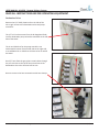
Destination Valves
Remove the 1/4” HDPE plastic wall on the side of the
unit to gain access to the destination valves and pump
controllers.
The 1/2” air line that comes from the Air Regulator feeds
into the destination pump controllers mounted on the left
side of the tower.
The air and CAN lines for the pump controllers run
underneath the tower from the left side to the right side,
so no additional air or CAN lines will have to be run within
the tower.
Run 3/4” hose from the grey plast-o-matic valves through
the pre-cut holes on the top of the unit and out to the
destinations where the chemical will be sent.
Be sure to secure the hose connections with hose clamps.
USER MANUAL (MODEL: ALX-RDS) Page 8 of 58
11/01/2014
USER MANUAL: ALX-RDS - Remote Delivery System
READ ALL INSTRUCTIONS BEFORE OPERATING EQUIPMENT
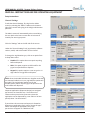
Setup Instructions
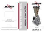
General Settings
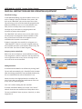
To edit the General Settings, first log into the Admin
screen by selecting the “Admin” button on the bottom
right of the screen and typing in the 4-digit administrator
passcode.
The Admin screen will automatically time out and bring
the user back to the home screen after 10 minutes of
inactivity for security purposes.
Click the “Settings” tab on the left side of the screen.
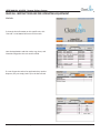
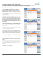
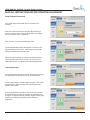
Under the “General Settings” tab, jug selection, software
version, model, and serial number can be viewed.
To change the Jug Selection type, click on an option from
its drop-down menu.
• Disabled: This option does not require anything
before a dispense.
• RFID: This option requires an RFID card for the
jug to be swiped before a dispense.
• Keypad: this option requires a user to type in a 4
digit code for the jug before a dispense.
NOTE: Since the ALX-RDS includes two 10-gallon tanks that
are mounted inside the unit, any Jug Selection options will
be invalid. The Jug Selection options are for the
ALX-600 system, which requires jugs to be placed on the
scale before each dispense.
Dispense Applications (Dispense Recipes) are assigned
permissions on Cleanintel.com. To tell the unit to
reference those permissions (how many times the
application can be dispensed by a user within a 24 hour
period) select “Use Permissions.”
If permissions do not matter and anyone is allowed to
dispense any application freely, select “Access All Apps.”
When users dispense applications then, their
permissions will appear as “9999 Uses Left.”
USER MANUAL (MODEL: ALX-RDS) Page 9 of 58
11/01/2014
USER MANUAL: ALX-RDS - Remote Delivery System
READ ALL INSTRUCTIONS BEFORE OPERATING EQUIPMENT
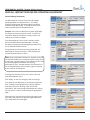
General Settings (Continued)
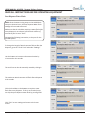
The Max Dispense Time sets a time limit for weightbased applications to dispense within. This safety
feature provides partial protection against accidental
overflows when dispensing. To change the time limit,
select an option from the dropdown menu.
Example: A user starts to dispense a 1 gallon application,
but forgets to place the jug on the scale. The unit will
continue to dispense for forever since the scale is not
reading any increases in weight.
If the Max Dispense Time is set at 5 minutes, the dispense will automatically terminate after 5 minutes,
therefore preventing chemical being dispensed all over
for an unlimited amount of time.
If large amounts of chemical are being dispensed, the
Max Dispense Time must be set in a way that will not
end the dispense before it is done.
NOTE: Since the ALX-RDS includes two 10-gallon tanks that
are mounted inside the unit and have hoses running directly into them, the Max Dispense Time options will be invalid
for protecting against accidental incorrect jug
placement by users. The Max Dispense Time features are
for the ALX-600 system, which requires jugs to be placed
on the scale for each dispense.
To change the timezone on the unit, select a new one
from the dropdown menu.
Click “Apply” to save any changes made on this page.
Every time the unit dispenses, it records the weight and
time, creating a learning algorithm to help it dispense
accurately every time. Clicking “Clear All Learned
Calibrations” will erase the logs of the dispenses, making
the unit have to “relearn” how to dispense applications
again.
Clicking this will not stop the unit from being able to perform, but it may take 4 to 5 dispenses again before the
unit’s calibrations are exact again.
USER MANUAL (MODEL: ALX-RDS) Page 10 of 58
11/01/2014
USER MANUAL: ALX-RDS - Remote Delivery System
READ ALL INSTRUCTIONS BEFORE OPERATING EQUIPMENT
Sleep Function
To prevent the computer from building up too much heat
inside the control box, the unit will begin a
“Sleep Function” after 90 minutes of inactivity.
After 80 minutes of inactivity, the unit will load a screen
that says “Preparing to Sleep.” This screen will appear
for 10 minutes before turning the screen off. Press any
number key on the keypad to remove this screen and go
back to the home page.
When the unti goes to sleep, the screen will turn off, but
the blue light on the monitor, the red light on the RFID
reader, and the green lights on the pump controllers will
all stay on.
To wake up the unit, simply move or click the mouse
on the control box. This will bring up a loading screen
where the unit will “wake up,” which will take between
30 and 60 seconds.
Once the home screen appears, the unit can be used
again.
USER MANUAL (MODEL: ALX-RDS) Page 11 of 58
11/01/2014
USER MANUAL: ALX-RDS - Remote Delivery System
READ ALL INSTRUCTIONS BEFORE OPERATING EQUIPMENT
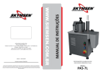
Site Info
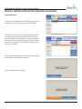
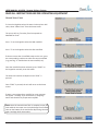
To view the Site Information on this specific unit, click
“Site Info” in the bottom left corner of the screen.
Here the Applications and their codes, Jugs, Users, and
Chemicals assigned to this unit can be viewed.
If a user forgets the code of an application they need to
dispense, they can simply look it up in the Site Info tab.
USER MANUAL (MODEL: ALX-RDS) Page 12 of 58
11/01/2014
USER MANUAL: ALX-RDS - Remote Delivery System
READ ALL INSTRUCTIONS BEFORE OPERATING EQUIPMENT
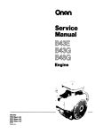
RFID Association
To associate an RFID card to a user in the system,
allowing them to log in by swiping their card, log into the
Admin screen by selecting the “Admin” button on the
bottom right of the screen and typing in the 4-digit
administrator passcode.
Select “Easy Add” on the left side of the screen.
Select a user from the dropdown menu.
Once the user is selected, scan the corresponding RFID
card to enter it into the system.
Once the card has scanned, the code will appear in the
text box. Click “Add.”
USER MANUAL (MODEL: ALX-RDS) Page 13 of 58
11/01/2014
USER MANUAL: ALX-RDS - Remote Delivery System
READ ALL INSTRUCTIONS BEFORE OPERATING EQUIPMENT
RFID Association (Continued)
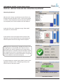
A dialog box will appear saying “RFID Added Successfully.”
Click “OK” to clear this message.
If the dialog box says “Easy Add Failed,” ensure that the unit
has an internet connection, reboot the unit, and attempt to
Easy Add again.
Press “STOP” twice or press the HOME key to return to the
home screen and sync the unit. This will send the RFID
information up to cleanintel.com. (See Page 29 for
instructions on syncing).
Once the sync has finished, the user will be able to log in by
swiping that RFID card.
If the user looks at “Users” under Site Info, they will see the
RFID number assigned to them if there is one.
Repeat this process for as many users and RFID cards as
required. Syncing must occur between each user.
Each user must be synced one at a time.
NOTE: Only one card can be assigned per user, and cards
cannot be shared between other users.
USER MANUAL (MODEL: ALX-RDS) Page 14 of 58
11/01/2014
USER MANUAL: ALX-RDS - Remote Delivery System
READ ALL INSTRUCTIONS BEFORE OPERATING EQUIPMENT
Pump Controller Settings
To be able to dispense chemical with the ALX-RDS, the
following items must be setup under the Pump Controller
settings:
• Each chemical being dispensed must be be assigned to a
pump controller.
• Water must be assigned to a pump controller.
• The Delivery Pump (the pump mounted on each side of
the MDS that sends the chemical from the tanks to the
destinations) must be assigned to a pump controller.
• Each Destination (where the chemical will be sent) must
be assigned to a valve.
• The Water Flush must be assigned to a valve.
• The Manifold Lock must be assigned to a valve.
To edit Pump Controller Settings, log into the Admin screen
by selecting the “Admin” button on the bottom right of the
screen and typing in the 4-digit administrator passcode.
Click on the “Settings” tab on the left side of the screen,
then click on the “Pumps” tab near the top of the screen.
This will bring up a list of all the pump controllers connected
to this unit.
Connected pumps will appear as “Ok” while disconnected
pumps will appear as “Missing.” If a pump is missing, check
its connections to the unit and see if it has a green light,
signaling power.
Select a pump from the list by clicking on it. The selected
pump will be highlighted in orange.
Click “Identify” to make the pump controller blink red for
a few seconds. This allows a user to ensure that the pump
controller they are editing is connected to the right pump.
To change the assignment of a pump (which chemical it’s set
up to dispense) select the pump and click the “Assignments”
tab. This brings up a list of all the chemicals that are set
up on this unit. Select the chemical that this pump will be
dispensing.
Next, click the button underneath the “Assignments” tab
that says “Manifold A.” Here a user can tell the unit which
dispense manifold this chemical is located on
(acids or caustics).
USER MANUAL (MODEL: ALX-RDS) Page 15 of 58
11/01/2014
USER MANUAL: ALX-RDS - Remote Delivery System
READ ALL INSTRUCTIONS BEFORE OPERATING EQUIPMENT
Pump Controller Settings (Continued)
Click “Apply” to finalize changes.
After clicking “Apply,” a dialog box will appear saying “Must
Update Calibrations for Pump!”
This message only applies if the pump is going to be
dispensing chemical by calibrated time.
NOTE: Since the ALX-RDS includes two 10-gallon tanks
that are mounted on top of the scales, it will not need to
dispense applications via time-based dispensing, meaning that pump controllers shouldn’t ever need to be time
calibrated. Pump calibrations are for the ALX-600 system,
which can dispense to foamers or bulk tanks that cannot
be measured by weight when dispensing.
Migrating Pumps
To move a pump’s settings (including calibrations and
assignment) to a different pump controller, select the
pump to be moved and click “Migrate.”
This brings up a dialog box that asks which new pump the
old pump’s configuration will be moved to.
Select the pump controller from the dropdown menu and
click “Migrate.”
If the new pump controller had no chemicals previously
assigned, the process will be complete. If the new pump
controller had a previous assignment, an alert will appear
warning that the previous configuration will be overwritten.
USER MANUAL (MODEL: ALX-RDS) Page 16 of 58
11/01/2014
USER MANUAL: ALX-RDS - Remote Delivery System
READ ALL INSTRUCTIONS BEFORE OPERATING EQUIPMENT
Deleting Pumps
To remove a pump from the system, select the pump and
click “Delete.”
This will bring up a dialog box for confirmation.
If the unit dispenses applications by calibrated time, the
calibrations will be removed and have to be added again
later.
Click “Yes” to remove the pump.
Deleting pumps should be a rare occurrence and should
only happen when a pump controller breaks and is
replaced.
If the pump controller is not broken, but is deleted, it will
automatically show up in the list of pumps again with no
assignments.
USER MANUAL (MODEL: ALX-RDS) Page 17 of 58
11/01/2014
USER MANUAL: ALX-RDS - Remote Delivery System
READ ALL INSTRUCTIONS BEFORE OPERATING EQUIPMENT
Destination Valve Settings
To edit Destination Valve Settings, log into the Admin
screen by selecting the “Admin” button on the bottom
right of the screen and typing in the 4-digit administrator
passcode.
The following steps are very similar to assigning chemicals
to pump controllers.
Click on the “Settings” tab on the left side of the screen.
Click on the “Valves” tab near the top of the screen. This
will bring up a list of all the Destination Valves assigned to
this unit. At least one valve must be assigned to “Flush”
and one must be assigned to a destination before the unit
can dispense.
Connected valves will appear as “Ok” while disconnected
valves will appear as “Missing.” If a valve is missing, check
its connections to the unit and see if it has a green light,
signaling power.
Select a valve from the list by clicking on it. The selected
valve will be highlighted in orange.
Click “Identify” to make the valve controller blink red for
a few seconds. This allows a user to ensure that the valve
controller they are editing is connected to the right valve.
To change the assignment of a valve (which destination it’s
set up to send chemical to) select it and click the “Assignments” tab. This brings up a list of all the destinations that
are set up on this unit.
Select the membrane to which this valve will be sending
chemical.
Next, click the button underneath the “Assignments” tab
that says “Manifold A.” Here a user can tell the unit from
which dispense manifold this destination will receive the
chemical.
Click “Apply” to finalize changes.
USER MANUAL (MODEL: ALX-RDS) Page 18 of 58
11/01/2014
USER MANUAL: ALX-RDS - Remote Delivery System
READ ALL INSTRUCTIONS BEFORE OPERATING EQUIPMENT
Deleting Valves
To remove a destination valve from the system, select the
pump and click “Delete.”
This will bring up a dialog box for confirmation.
Click “Yes” to remove the valve.
Deleting valves should be a rare occurrence and should
only happen when a valve controller breaks and is replaced.
If the valve controller is not broken, but is deleted, it will
automatically show up in the list of valves again, but with
no assignments.
USER MANUAL (MODEL: ALX-RDS) Page 19 of 58
11/01/2014
USER MANUAL: ALX-RDS - Remote Delivery System
READ ALL INSTRUCTIONS BEFORE OPERATING EQUIPMENT
Manifold Settings
To edit Manifold Settings, log into the Admin screen, click
on the “Settings” tab on the left side of the screen, and
click on the “Manifolds” tab near the top of the screen.
This will bring up a list of all the chemicals assigned to the
different manifolds on this unit. To view different manifolds, click on the drop-down menu and select one.
See Page 14 for instructions on assigning water and
chemicals to pumps and manifolds.”
The “Manifolds” tab is where users can see which chemicals and pumps are assigned to which manifolds so that
they can be certain that acids are all together on one
manifold and all caustics are on another.
If Water is assigned to the manifold, it will appear as a
“Valid Manifold.” If there is no water assigned (meaning
that manifold cannot do a post-dispense water rinse), the
unit will show “You have no water assigned.”
Assigning Scales to Manifolds
Before the unit can dispense, each manifold must have a
scale assigned to it. Select a scale from the drop-down list
on the right side of the screen. Be sure to assign the correct scale to the correct manifold.
Adding Manifolds
A manifold can be added in the software by clicking “Add.”
The unit will automatically call it “Manifold” with the letter
after the existing manifolds (if two manifolds already exist,
the new manifold will be named “Manifold C” etc).
Select the color to be displayed with this manifold. The
color chosen does not affect the performance of the unit.
It only acts as a reference guide.
Click “Yes” to finish adding the new manifold.
If another manifold is added, the “Pumps” and “Valves”
tabs will show the new manifold in the drop-down menu.
The new manifold will have no pumps, chemicals, or scales
assigned to it.
USER MANUAL (MODEL: ALX-RDS) Page 20 of 58
11/01/2014
USER MANUAL: ALX-RDS - Remote Delivery System
READ ALL INSTRUCTIONS BEFORE OPERATING EQUIPMENT
Deleting Manifolds
To remove the manifold from the software, go back to the
Manifolds tab, select the manifold, and click “Delete.”
If the manifold has chemicals or destinations assigned to
it, the pump controllers and destination valves must be
moved to a different manifold in the software before the
old manifold can be removed. Otherwise a screen will appear with a warning that a manifold with assigned chemicals can’t be deleted.
If no chemicals or destinations are setup on that manifold,
a dialog box for confirmation will appear.
Click “Yes” to delete the manifold.
USER MANUAL (MODEL: ALX-RDS) Page 21 of 58
11/01/2014
USER MANUAL: ALX-RDS - Remote Delivery System
READ ALL INSTRUCTIONS BEFORE OPERATING EQUIPMENT
Priming Pumps
Before the unit can dispense chemical, each pump must be
primed so the chemical fills up the hose to the manifold
Before the pumps can be primed, make sure that one pump
controller is assigned to water for that manifold so a water
flush can be performed between priming pumps. See Page
14 for instructions on assigning water and chemical to pump
controllers.
Select the pump to be primed from the Pumps list, then click
“Prime Pump.”
This will bring up a dialog box where the user can prime the
pump and bring chemical through the hoses.
Press START to turn the pump on. Once chemical is through
the entire hose and is dispensing through the manifold into
the 10 gallon tank, press STOP to turn the pump off.
Click “Close” when priming has been completed.
Once the pump has been primed and chemical is in the 10
gallon tank, the chemical must be removed via the
ball valve on the bottom of the tank before more pumps can
be primed.
Point the discharge hose on the bottom of the tank into a jug
or drain, then open the ball valve on the bottom of the 10
gallon tank.
Once all of the chemical has been removed from the tank,
select the pump controller assigned to “Water” on that manifold, and prime it. This will rinse out the tank and flush the
manifold so that another pump with chemical can be primed
Once the tank has been rinsed and the manifold has been
flushed, open the ball valve on the bottom of the tank again
to remove the water. Close the ball valve when the tank is
empty, and repeat this process for each pump.
Ensure that the ball valve is closed before dispensing!
USER MANUAL (MODEL: ALX-RDS) Page 22 of 58
11/01/2014
USER MANUAL: ALX-RDS - Remote Delivery System
READ ALL INSTRUCTIONS BEFORE OPERATING EQUIPMENT
Calibrating the Scale
To calibrate the scales to ensure the best accuracy when
dispensing, first log into the Admin screen by selecting the
“Admin” button on the bottom right of the screen and typing in the 4-digit admin passcode.
Select “Calibrate” on the left side of the screen, then click
“Scale” on the top of the screen.
Select a scale from the drop-down menu.
If this is the first time calibrating the scale, both sides will
appear red with an exclamation point.
Make sure there is nothing on the 10 gallon tank mounted
on the scale, and that the tank is empty, then click “Tare
Scale.”
Next, place a dumbbell, or a weight on top of the tank.
The specific weight of this object must be known to ensure
complete accuracy.
Using the numbers on the keypad, type in the weight of
the dumbbell and click “Calibrate Scale.”
Both sides will appear green with check marks, signaling
that the scale is fully calibrated.
If the scale must be recalibrated, click “Tare Scale” and
start over. This will wipe all previous calibration values
and will require the user to recalibrate the scale before
dispensing again.
Clean Logix recommends recalibrating the scale every 2-3
months to ensure the best accuracy.
USER MANUAL (MODEL: ALX-RDS) Page 23 of 58
11/01/2014
USER MANUAL: ALX-RDS - Remote Delivery System
READ ALL INSTRUCTIONS BEFORE OPERATING EQUIPMENT
Pump Calibration
NOTE: Since the ALX-RDS includes two 10-gallon tanks
that are mounted on top of the scales, it will not need to
dispense applications via time-based dispensing, meaning that pump controllers shouldn’t ever need to be time
calibrated. Pump calibrations are for the ALX-600 system,
which can dispense to foamers or bulk tanks that cannot
be measured by weight when dispensing.
Disregard the following instructions as pump controllers
on an ALX-RDS system will not need to be calibrated for
time-based dispenses.
To calibrate the pumps for time-based dispenses, log into
the Admin screen by selecting the “Admin” button on the
bottom right of the screen and typing in the 4-digit admin
passcode.
Select “Calibrate” on the left side of the screen, then click
“Pump” on the top of the screen.
Select a pump from the drop-down menu. Only pumps
that have been assigned a chemical will appear in this list.
The unit needs to know how much chemical it pumps out
for a set amount of time, so to calibrate it for timed
dispenses, it must have calibration points setup close to
the regular amounts of chemical that will be dispensed.
The unit’s text will read:
“Calibrate Pump - Without a few calibration points close
to your regular dispense amounts, the unit will not
perform up to its capability.
To add a calibration, click the button below.”
Click “Add Calibration Point.”
The onscreen instructions will read:
“Run the Pump - Dispense a measure that is close to what
would normally be used.
Be sure that you dispense into a jug that will let you
accurately measure how much was dispensed.
You’ll stop the pump by pressing STOP.
To proceed, press the START button.”
Press START and dispense an amount close to what will
be normally dispensed (e.g. if users will be dispensing
one gallon of chemical, dispense one gallon of chemical
for a calibration point).
USER MANUAL (MODEL: ALX-RDS) Page 24 of 58
11/01/2014
USER MANUAL: ALX-RDS - Remote Delivery System
READ ALL INSTRUCTIONS BEFORE OPERATING EQUIPMENT
Pump Calibration (Continued)
Press STOP when the desired amount of chemical is
reached.
Enter the amount of chemical that was dispensed and
select the correct value from the drop-down menu (fluid
ounces, mililiters, liters, or gallons).
Click “Confirm” to save the calibration value.
The saved calibration values will appear in a table on the
right hand side of the screen. Clean Logix recommends
having 2 calibration points per pump.
Repeat this process with all of the pump controllers that
will be dispensing chemical via time. Once they are all
calibrated, the unit can dispense time-based applications.
Clearing Calibrations
To clear calibration points on pumps, select the pump from
the drop-down menu and click “Clear all Calibrations.”
The unit will bring up a confirmation message. Click “Clear
all Calibrations” again to erase all the timed calibration
points on this pump.
Clearing calibrations should be a rare occurance, but may
be required when changes in the plant environment (e.g.
change in air pressure, water pressure, length of hose, type
of pump, etc) affect the speed at which chemical is
dispensed.
USER MANUAL (MODEL: ALX-RDS) Page 25 of 58
11/01/2014
USER MANUAL: ALX-RDS - Remote Delivery System
READ ALL INSTRUCTIONS BEFORE OPERATING EQUIPMENT
Post-Dispense Water Flush
NOTE: Since the water rinsing steps on the ALX-RDS are
setup on cleanintel.com, the Post Dispense Water Flush
settings will not need to be used.
Make sure that the checkbox requiring a water flush after
every dispense is not selected, and that the number of
seconds to flush is set to “Zero.”
Disregard the following instructions, as they are for the
ALX-600 system.
To change the length of time that water flushes after the
dispense, go to the “Flush Time” tab under “Settings.”
Use the buttons to increase or decrease the time by
1.0 seconds or 0.1 seconds.
The scroll bar can also be manually moved by clicking it.
The maximum time that water will flush after a dispense
is 10 seconds.
Click the checkbox on the bottom to require a water
flush after every dispense. If this is not checked, users
can skip the post-dispense water flush by pressing STOP.
Click “Exit” to save settings and return to the home
screen.
USER MANUAL (MODEL: ALX-RDS) Page 26 of 58
11/01/2014
USER MANUAL: ALX-RDS - Remote Delivery System
READ ALL INSTRUCTIONS BEFORE OPERATING EQUIPMENT
Operation Instructions
Dispensing
To begin dispensing, the user can either swipe their RFID
card or type in their 4-digit passcode to login.
Correct passcodes will bring the user to the next screen
while incorrect codes will appear in red.
Select an application to dispense by typing in its 4-digit
code.
Once the application has been selected, the unit shows the
name, location, manifold, and allowed uses of the
application.
NOTE: If any errors appear on this screen, refer to the
Validation Errors troubleshooting guide. (See Page 34).
Press START to confirm the application and continue.
USER MANUAL (MODEL: ALX-RDS) Page 27 of 58
11/01/2014
USER MANUAL: ALX-RDS - Remote Delivery System
READ ALL INSTRUCTIONS BEFORE OPERATING EQUIPMENT
Dispensing (Continued)
NOTE: Under no circumstances interfere with the scale
during a dispense. This includes touching the tank or frame,
lifting up on the tank during a dispense, leaning or placing
any additional weight on the scale, etc. This will cause incorrect readings and reporting on chemical consumption.
Press START to begin the dispense.
Example: This application is dispensing 3 gallons of
“Chemical 1,” with a 1 gallon water rinse. The total amount
of the application is “4 gallons” which is shown above the
right bar.
The first step in the application is to measure out 3 gallons
of “Chemical 1” by dispensing it into the 10 gallon tank.
The bar on the left of the screen shows the current volume
in gallons for the step of the application being dispensed.
The bar on the right shows the total volume of the application, which includes both the chemical and the water rinse.
The second step begins and pumps “Chemical 1” out of the
10 gallon tank via the delivery pump and sends it to the
“Dairy Membrane 1” destination through the destination
valve that is assigned to “Dairy Membrane 1.” (See Page 17
for instructions on assigning/changing destinations).
The delivery pump will stop when the scale reaches “zero”
weight. After a short pause, the pump will run again for a
few seconds to ensure the tank is completely empty.
The unit then dispenses 1 gallon of water to rinse out the
tank. Once the tank is rinsed, the delivery pump sends the
water out through the pump and chemical lines, and into
the membrane system, emptying the tank.
USER MANUAL (MODEL: ALX-RDS) Page 28 of 58
11/01/2014
USER MANUAL: ALX-RDS - Remote Delivery System
READ ALL INSTRUCTIONS BEFORE OPERATING EQUIPMENT
Dispensing (Continued)
After the tank is empty, a post-dispense water flush is sent
through the pump and delivery lines, via the valve assigned
to “Flush,” to the membrane to ensure the pump and lines
are completely free of chemical before the next dispense.
At the end of the cycle, a dialog box saying “Please Wait”
will appear for a few seconds.
A post-dispense screen will appear with the name of the
application, the total volume that was actually dispensed,
and the dispense time of how long it took to complete.
NOTE: Ignore the “Remove Jug” message on the unit. This
message applies to the ALX-600, which requires users to
place jugs on the scale for dispensing, then remove them
when the dispense is complete. Since the ALX-RDS includes
two 10-gallon tanks that are mounted on top of the scales,
and sends chemical out to remote destinations, no jugs will
have to be added or removed for a dispense.
If another dispense is required, press START to return to the
application selection screen. If dispensing is done, press
STOP to return to the home screen.
USER MANUAL (MODEL: ALX-RDS) Page 29 of 58
11/01/2014
USER MANUAL: ALX-RDS - Remote Delivery System
READ ALL INSTRUCTIONS BEFORE OPERATING EQUIPMENT
Syncing
To sync information to and from cleanintel.com, press
the “Sync” button in the bottom right corner of the home
screen.
This will automatically initiate a data transfer from the
unit to the website and back again through the cellular
router.
The unit will sync up all the data logs of dispenses including which users have logged in, how much chemical has
been dispensed, which applications have been used, and
the times and durations for all dispenses.
If a manager has created a new user, updated the list of
chemicals or applications, or added new user permissions
on cleanintel.com, the syncing process will update the unit
with this new data.
The unit is configured to sync to cleanintel.com hourly, so
a user will rarely need to manually sync.
If the syncing fails, ensure the unit has internet connection by checking the router for 3 green lights on the right
(meaning full signal) and that all connections are securely
in place. If a yellow light is on, it shows that the router has
poor signal. A red light means no service.
USER MANUAL (MODEL: ALX-RDS) Page 30 of 58
11/01/2014
USER MANUAL: ALX-RDS - Remote Delivery System
READ ALL INSTRUCTIONS BEFORE OPERATING EQUIPMENT
Manual Water Flush
To rinse the 10 gallon tanks with water via the spinner ball
valve, select “Water Flush” from the home screen.
The screen will say “Press Key That Corresponds to
Manifold for Flush.”
Press “1” on the keypad to select the Red manifold.
Press “2” on the keypad to select the Blue manifold.
If there are more than 2 manifolds setup on the unit, press
the corresponding numbers to select the correct manifold
(e.g. pressing “3” would select the next manfold, etc).
Once the manifold has been selected, press “START” on
the keypad to manually rinse with water.
The water will continue to dispense until “STOP” is
pressed.
Once “STOP” is pressed, the unit will return to the home
screen.
If water is not assigned to a manifold, an error message
will appear. See Page 14 for instructions on assigning
water and chemicals to pumps and manifolds.
NOTE: Once the manual water flush is complete, empty the
tank and drain the water out via the discharge hose and ball
valve on the bottom of the tank before dispensing chemical
again. See Page 40 for instructions.
USER MANUAL (MODEL: ALX-RDS) Page 31 of 58
11/01/2014
USER MANUAL: ALX-RDS - Remote Delivery System
READ ALL INSTRUCTIONS BEFORE OPERATING EQUIPMENT
Maintenance Instructions
Scale Maintenance
WARNING
Avoid Personal Injury
1. Avoid contact of cleaning agent with skin and
eyes. If contact occurs, see MSDS sheet for
further first aid measures.
2. Follow safety instructions of chemical
manufacturer (MSDS).
3. Always follow plant and OSHA guidelines
about the use of hygiene equipment.
4. Disconnect power before servicing unit.
Sometimes debris or foreign objects can get underneath
the scales and cause incorrect readings or dispense errors.
Use the following instructions to perform maintenance on
the scales.
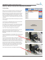
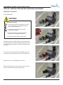
To access the scales underneath the 10 gallon tanks, the
tanks must be disconnected from the air and water lines.
Remove the 1/4” airline leading into the valve.
Release the clamps on the cam coupler so the 3/4” hose
can be removed from the plast-o-matic valve.
USER MANUAL (MODEL: ALX-RDS) Page 32 of 58
11/01/2014
USER MANUAL: ALX-RDS - Remote Delivery System
READ ALL INSTRUCTIONS BEFORE OPERATING EQUIPMENT
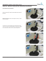
Scale Maintenance (Continued)
Disconnect the 3/8” water line that feeds into the top of
the tank.
Release the clamps on the cam coupler so the 1/2” hose
can be removed.
The tanks can now be lifted up and removed to provide
access to the scale assemblies below. Remove any debris
on or around the scale to ensure accurate dispenses.
USER MANUAL (MODEL: ALX-RDS) Page 33 of 58
11/01/2014
USER MANUAL: ALX-RDS - Remote Delivery System
READ ALL INSTRUCTIONS BEFORE OPERATING EQUIPMENT
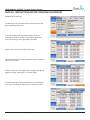
Standard & Event Logs
The data logs on the ALX-RDS can be used to see what has
been happening on the unit.
To access the data logs, log into the Admin screen by
selecting the “Admin” button on the bottom right of the
screen and typing in the 4-digit admin passcode.
Select “Logs” from the left side of the screen.
The Standard Logs show which applications were dispensed
when, by which user.
If there is more than one page of logs, navigate through the
pages by clicking “Next Page” or “Previous Page.”
The Event Logs show each individual action that took place
on the unit, including all button presses and pointer clicks.
USER MANUAL (MODEL: ALX-RDS) Page 34 of 58
11/01/2014
USER MANUAL: ALX-RDS - Remote Delivery System
READ ALL INSTRUCTIONS BEFORE OPERATING EQUIPMENT
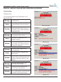
Troubleshooting
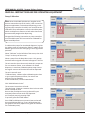
Validation Errors
Use the following guides to help troubleshoot if errors
appear on the unit.
Message
Cause
Solution
Message
Cause
Invalid App Code
The code typed in does not reference any
existing application setup on cleanintel.
com.
Check the Site Info tab to see the
existing applications setup on the unit,
then type in a correct code to dispense an
existing application.
Not all Chemicals Have a Pump
A chemical in the application is not
assigned to a pump.
Solution
Ensure all pump controllers have power.
On unit, go into the Admin screen, then
under “Pumps” tab. Assign the chemical
to a pump. (See Page 14).
Message
No Delivery Pump Assigned to the
Current Manifold
Cause
No pump controller is assigned to the
delivery pump.
Solution
Go to the admin screen, then under the
“Pumps” tab ensure that a pump on each
manifold is assigned to “Delivery.” (See
Page 14).
Message
The Delivery Pump Assigned to the
Current Manifold is Missing
Cause
The pump controller assigned to the
Delivery Pump is disconnected.
Solution
Check for a green light on the pump controller, signaling power. Check all the CAN
connections to the pump controllers.
USER MANUAL (MODEL: ALX-RDS) Page 35 of 58
11/01/2014
USER MANUAL: ALX-RDS - Remote Delivery System
READ ALL INSTRUCTIONS BEFORE OPERATING EQUIPMENT
Troubleshooting (Continued)
Message
Cause
Solution
Message
Cause
Solution
No Destination Valve Assigned to the
Current Manifold
No valve is assigned to the destination of
the application that is trying to be
dispensed on that manifold.
Go to the admin screen, then under the
“Valves” tab ensure that a valve is
assigned to the correct destination on that
manifold. (See Page 17).
The Destination Valve Assigned to the
Current Manifold is Missing
The valve controller assigned to the
Destination in the application is
disconnected.
Check for a green light on the pump
controller, signaling power. Check all the
CAN connections to the pump controllers.
Message
No Flush Valve Assigned to the Current
Manifold
Cause
No valve is assigned to the Flush on that
manifold.
Solution
Go to the admin screen, then under the
“Valves” tab ensure that a valve is
assigned to “Flush” on that manifold. (See
Page 17).
Message
The Flush Valve Assigned to the Current
Manifold is Missing
Cause
The valve controller assigned to the
Flush on that manifold is disconnected.
Solution
Check for a green light on the pump
controller, signaling power. Check all the
CAN connections to the valve controllers.
USER MANUAL (MODEL: ALX-RDS) Page 36 of 58
11/01/2014
USER MANUAL: ALX-RDS - Remote Delivery System
READ ALL INSTRUCTIONS BEFORE OPERATING EQUIPMENT
Troubleshooting (Continued)
Message
Cause
Solution
The Manifold Lock Valve is Missing
No valve is assigned to manifold lock on
the manifold of the application that is trying to be dispensed.
Go to the admin screen, then under the
“Valves” tab ensure that a valve is
assigned “Manifold Lock” on that
manifold. (See Page 17).
USER MANUAL (MODEL: ALX-RDS) Page 37 of 58
11/01/2014
USER MANUAL: ALX-RDS - Remote Delivery System
READ ALL INSTRUCTIONS BEFORE OPERATING EQUIPMENT
Troubleshooting (Continued)
Message
Cause
Solution
Message
Cause
Solution
Message
Cause
Solution
Message
Cause
Solution
No App Permissions Set Up
No permissions to dispense this
application have been setup for this user
on cleanintel.com.
On website, edit the user’s permissions to
be able to dispense that application, then
sync the unit. Alternative: under General
Settings select “Don’t Use Permissions”
(See Page 9).
Too Many Uses
The application has been dispensed by
that particular user to their max permission level within a 24-hour period.
On website, edit the user’s permissions to
be able to dispense that application more
times within a 24-hour period, then sync
the unit. Alternative: under General
Settings select “Don’t Use Permissions”
(See Page 9).
Not All Chemicals on Same Manifold
The application trying to dispense has
multiple chemicals, but not all are
assigned to the same manifold.
On unit, go into the Admin screen, then
under “Pumps” tab. Assign the chemicals
in the application to the same manifold.
(See Page 14).
No Water Pump (Water Flush Required)
Water is not assigned to the manifold that
has an application that is trying to
dispense, but a post-dispense water flush
is required.
On unit, go into the Admin screen, then
under “Pumps” tab and assign water to
the correct manifold, or go under the
“Flush Time” tab and deselect “Require a
flush after each dispense.” (See Page 25).
USER MANUAL (MODEL: ALX-RDS) Page 38 of 58
11/01/2014
USER MANUAL: ALX-RDS - Remote Delivery System
READ ALL INSTRUCTIONS BEFORE OPERATING EQUIPMENT
Troubleshooting (Continued)
Message
No Scale Assigned to this Manifold
Cause
The scale has not been assigned to a specific manifold in the admin screen.
Solution
If the loadcell has a red light, signaling
power, go into the Admin screen and
assign the scale to a manifold under the
“Manifolds” tab. (See Page 19).
Message
The Scale is not Connected
Cause
The scale conditioner is not connected to
the CAN network.
Solution
Check for a red light on the scale conditioner signaling power, then check the
connection from the scale conditioner to
the scale.
Message
Scale is not Calibrated
Cause
The scale has not been calibrated.
Solution
On unit, go into the Admin screen, then
under “Calibrate” tab. Tare the scale, then
follow on-screen instructions to calibrate.
(See Page 22).
Message
Pump Needs Calibration
Cause
Solution
The application trying to dispense is
time-based and needs the pump to be
time-calibrated, but the pump is not.
On unit, go into the Admin screen, then
under “Calibrate” tab. Select which pump
to calibrate. (See Page 23).
USER MANUAL (MODEL: ALX-RDS) Page 39 of 58
11/01/2014
USER MANUAL: ALX-RDS - Remote Delivery System
READ ALL INSTRUCTIONS BEFORE OPERATING EQUIPMENT
Dispense Errors
NOTE: Ignore the “Remove Jug” message on the unit. This
message applies to the ALX-600, which requires users to
place jugs on the scale for dispensing, then remove them
when the dispense is complete. Since the ALX-RDS includes two 10-gallon tanks that are mounted on top of the
scales, and sends chemical out to remote destinations, no
jugs will have to be added or removed for a dispense.
Message
Cause
Dispense Cancelled
User pressed “STOP” before the dispense
finished.
Solution
During a dispense, do not press any
buttons until the screen shows a green
check mark signaling the end of the
dispense. If this error appears, press
“STOP” to return to the home screen.
Message
Jug Lifted Prematurely
Cause
Solution
Message
Cause
User interfered with the tank before the
dispense finished - causing incorrect scale
readings.
Make sure the tank and scale are not
touched during the dispense until the
screen shows a green check mark.
Scale Never Settled
Vibration caused the scale to be unable to
settle/tare itself before the dispense.
Solution
Remove anything that may physically
interfere with the scale. (See Page 31).
Message
Pump Activated, but no Chemical Arrived
Cause
No chemical arrived during the dispense.
Solution
Check that pump is primed and has an air
supply to it to turn it on. (See Page 21 for
priming pumps).
USER MANUAL (MODEL: ALX-RDS) Page 40 of 58
11/01/2014
USER MANUAL: ALX-RDS - Remote Delivery System
READ ALL INSTRUCTIONS BEFORE OPERATING EQUIPMENT
Troubleshooting (Continued)
Chemical Stuck in Tank
Use the following instructions if chemical becomes trapped in
the 10 gallon tank for any of the following reasons:
• A user cancelled the dispense before chemical was sent
out of the 10-gallon tank to the destination.
• A pump was being primed.
The tank can be emptied by manually opening the ball valve
on the bottom of the 10 gallon tank.
To manually empty the tank, first ensure that there is a
container in place underneath the tank to catch the chemical
when it comes out.
Ensure the discharge hose from the tank is pointed into the
container, then open the ball valve by turning the lever.
Once this is opened, chemical will begin to flow out.
Once all of the chemical is removed from the tank, close the
air valve.
Prime the pump for water on that manifold to rinse the
tank and flush the manifold. See Page 21 for instructions on
priming the pump for water.
After the tank has been rinsed and the manifold has been
flushed, open the ball valve on the bottom of the 10 gallon
tank again to remove the water from the tank and send it out
the discharge line.
Close the ball valve when completed.
Ensure that the ball valve is closed before dispensing,
otherwise chemical will leak out of the tank when a dispense
is run!
USER MANUAL (MODEL: ALX-RDS) Page 41 of 58
11/01/2014
USER MANUAL: ALX-RDS - Remote Delivery System
READ ALL INSTRUCTIONS BEFORE OPERATING EQUIPMENT
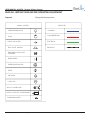
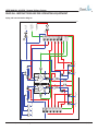
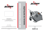
Piping and Instrumentation
Diagrams
6<0%2//(*(1'
/,1(67</(6
3,
35(6685(,1',&$725
3/80%,1*
&2035(66('$,5
3803
(/(&75,&$/
&+(&.9$/9(36,
(19(/23(
%$//9$/9(0$18$/
',$3+5$*09$/9($,5
23(5$7('
%/(('),77,1*
35(6685(5(*8/$725
),/7(5
$,5'5<(5
/&
/2$'&(//
81/(6627+(5:,6(63(&,),('
$/;3&&21752//(5
$/;6&/2$'&(//&21',7,21(5
6
$/;3&
$/;6&
7$1.5,16(12==/(
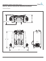
',0(16,216$5(,1,1&+(6
72/(5$1&(6
)5$&7,21$/ $1*8/$50$&+ %(1' 7:23/$&('(&,0$/ 7+5((3/$&('(&,0$/ USER MANUAL (MODEL: ALX-RDS) Page 42 of 58
7+(,1)250$7,21&217$,1('
,17+,6'5$:,1*,67+(62/(
3523(57<2)&/($1/2*,;
$1<5(352'8&7,21,13$57
25$6$:+2/(:,7+2877+(
:5,77(13(50,66,212)
&/($1/2*,;,6352+,%,7('
0$7(5,$/
'5$:1%<$=,(*(5
),1,6+
'$7(
7,7/($/;0'63,
127('(%855$1'%5($.
$//6+$53('*(6
:(,*+7/%
35235,(7$5<$1'&21),'(17,$/
,7(0180%(5
6&$/(
11/01/2014
USER MANUAL (MODEL: ALX-RDS) Page 43 of 58
5(9
$/;3&
$/;3&
$/;3&
$/;3&
$/;3&
6
6
6
6
6
'(67,1$7,21
%
/&
5(9,6,216
'(67,1$7,21
$
&$867,&
0$1,)2/'
*$/
7$1.
11/01/2014
'$7(
*$/
7$1.
&+$1*('/$<28772,1&/8'(',63(16(0$1,)2/'6:,7++<'52/2&.6(783
$''('7$1.5,16(12==/(6$1'),//:$1',17$1.6$''('0$18$/'5$,1
9$/9(672%277202)7$1.6$''('35(6685(5$7,1*672&+(&.9$/9(6,1 36,5(3/$&('48,&.(;+$8679$/9(6:,7+%/(('),77,1*6
'(6&5,37,21
),;('',5(&7,212)7$1.,1/(7&+(&.9$/9(6$''('0$18$/29(55,'(%$//
9$/9(6)25$,56833/<72'(67,1$7,2138036
$/;3&
6
6$1,7,=(5 $&,'
'(67,1$7,21
$
:(,*+7/%
),1,6+
0$7(5,$/
',0(16,216$5(,1,1&+(6
72/(5$1&(6
)5$&7,21$/ $1*8/$50$&+ %(1' 7:23/$&('(&,0$/ 7+5((3/$&('(&,0$/ 81/(6627+(5:,6(63(&,),('
'(67,1$7,21
%
/&
0$1,)2/'
127('(%855$1'%5($.
$//6+$53('*(6
'$7(
'5$:1%<$=,(*(5
7+(,1)250$7,21&217$,1('
,17+,6'5$:,1*,67+(62/(
3523(57<2)&/($1/2*,;
$1<5(352'8&7,21,13$57
25$6$:+2/(:,7+2877+(
:5,77(13(50,66,212)
&/($1/2*,;,6352+,%,7('
35235,(7$5<$1'&21),'(17,$/
$/;3&
$/;3&
$/;3&
$/;3&
$/;3&
$/;3&
3,
&2035(66('
$,56833/<
&$1%86
72&21752/
%2;
:$7(5
6833/<
6&$/(
,7(0180%(5
6+((72)
7,7/($/;0'63,',$*5$05(9
$/;6&
$/;6&
6
6
6
6
6
6
3,
USER MANUAL: ALX-RDS - Remote Delivery System
READ ALL INSTRUCTIONS BEFORE OPERATING EQUIPMENT
Piping and Instrumentation Diagram
USER MANUAL (MODEL: ALX-RDS) Page 44 of 58
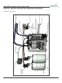
ACID
EXAMPLE PUMP
(1/2" YAMADA
AODD)
5
ALX-PC4X-V3
4
CAUSTIC
WEIGHT (LB.)
FINISH
11/01/2014
3
375.39
Material <not specified>
MATERIAL
DIMENSIONS ARE IN INCHES
TOLERANCES:
FRACTIONAL 1/16"
ANGULAR: MACH .5 BEND 2
TWO PLACE DECIMAL
.015"
THREE PLACE DECIMAL
.005"
UNLESS OTHERWISE SPECIFIED:
AIR SUPPLY
TO PUMPS
2
NOTE: DEBURR AND BREAK
ALL SHARP EDGES!
DATE: 10/28/2014
DRAWN BY: A. ZIEGER
THE INFORMATION CONTAINED
IN THIS DRAWING IS THE SOLE
PROPERTY OF CLEAN-LOGIX.
ANY REPRODUCTION IN PART
OR AS A WHOLE WITHOUT THE
WRITTEN PERMISSION OF
CLEAN-LOGIX IS PROHIBITED.
PROPRIETARY AND CONFIDENTIAL!
SCALE: 1:16
ITEM NUMBER:
1
SHEET 1 OF 1
Default
TITLE: ALX-MDS EXAMPLE SYSTEM REV101
AIR SUPPLY
WATER SUPPLY
DESTINATION VALVE ASSEMBLY
(ALX-MDS-DEST-5 SHOWN)
ALX-MDS
(SIDE COVER
REMOVED FOR
CLARITY)
ALX-COMP-SA
CAN COMMUNICATION
LINES
PLUMBING TO
DESTINATIONS
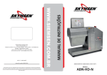
USER MANUAL: ALX-RDS - Remote Delivery System
READ ALL INSTRUCTIONS BEFORE OPERATING EQUIPMENT
Example System Layout
5(9
5(9,6,216
'(6&5,37,21
USER MANUAL: ALX-RDS - Remote Delivery System
'$7(
&+$1*('6<67(0'(6,*172$+<'52/2&.('
',63(16(0$1,)2/'7235(9(179$32535(6685(
%8,/'83)25&,1*&+(&.9$/9(623(1$1'
$//2:,1*&+(0,&$/72/($.,1727$1.6$''('),//
:$1'727$1.72),//)520%27720:,&+5('8&(6
6+$.,1*$1',03529(6,1&203$7,%/(&+(0,&$/
Dimensions
Diagram
6(3$5$7,21$''('*5$&2'(/,9(5<3803672%20
$''('9,721*$6.(7672$//&$0/2&.),77,1*6
READ ALL INSTRUCTIONS BEFORE OPERATING EQUIPMENT
81/(6627+(5:,6(63(
USER MANUAL (MODEL: ALX-RDS) Page 45 of 58
',0(16,216$5(,1,1&+
72/(5$1&(6
)5$&7,21$/ $1*8/$50$&+ 7:23/$&('(&,0$/
7+5((3/$&('(&,0$/
11/01/2014
0$7(5,$/
0DWHULDOQRWVSHF
),1,6+
5(9
USER MANUAL (MODEL: ALX-RDS) Page 46 of 58
'$7(
11/01/2014
),1,6+
0DWHULDOQRWVSHFLILHG!
0$7(5,$/
',0(16,216$5(,1,1&+(6
72/(5$1&(6
)5$&7,21$/ $1*8/$50$&+ %(1' 7:23/$&('(&,0$/ 7+5((3/$&('(&,0$/ 81/(6627+(5:,6(63(&,),('
'$7(
'5$:1%<$=,(*(5
7+(,1)250$7,21&217$,1('
,17+,6'5$:,1*,67+(62/(
3523(57<2)&/($1/2*,;
$1<5(352'8&7,21,13$57
25$6$:+2/(:,7+2877+(
:5,77(13(50,66,212)
&/($1/2*,;,6352+,%,7('
35235,(7$5<$1'&21),'(17,$/
,7(0180%(5$/;0'6
7,7/($/;0'65(9
6(('(7$,/21
1(;73$*(
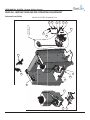
Exploded Views/BOMs
&+$1*('6<67(0'(6,*172$+<'52/2&.('
',63(16(0$1,)2/'7235(9(179$32535(6685(
%8,/'83)25&,1*&+(&.9$/9(623(1$1'
$//2:,1*&+(0,&$/72/($.,1727$1.6$''('),//
:$1'727$1.72),//)520%27720:,&+5('8&(6
6+$.,1*$1',03529(6,1&203$7,%/(&+(0,&$/
6(3$5$7,21$''('*5$&2'(/,9(5<3803672%20
$''('9,721*$6.(7672$//&$0/2&.),77,1*6
5(9,6,216
'(6&5,37,21
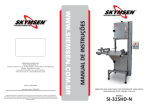
USER MANUAL: ALX-RDS - Remote Delivery System
READ ALL INSTRUCTIONS BEFORE OPERATING EQUIPMENT
Model ALX-RDS | Exploded View
USER MANUAL: ALX-RDS - Remote Delivery System
READ ALL INSTRUCTIONS BEFORE OPERATING EQUIPMENT
Model ALX-RDS | Exploded View
'$7(
(
),//
&(6 $/
20
6
81/(6627+(5:,6(63(&,),('
',0(16,216$5(,1,1&+(6
72/(5$1&(6
)5$&7,21$/ $1*8/$50$&+ %(1' 7:23/$&('(&,0$/ 7+5((3/$&('(&,0$/ ),1,6+
'$7(
of 58
USER MANUAL (MODEL: ALX-RDS) Page 47
7+(,1)250$7,21&217$,1('
,17+,6'5$:,1*,67+(62/(
3523(57<2)&/($1/2*,;
$1<5(352'8&7,21,13$57
25$6$:+2/(:,7+2877+(
:5,77(13(50,66,212)
&/($1/2*,;,6352+,%,7('
'5$:1%<$=,(*(5
:(,*+7/%
35235,(7$5<$1'&21),'(17,$/
0$7(5,$/
0DWHULDOQRWVSHFLILHG!
127('(%855$1'%5($.
$//6+$53('*(6
7,7/($/;0'65(9
,7(0180%(5$/;0'6
6&$/(
6+((72)
11/01/2014
USER MANUAL: ALX-RDS - Remote Delivery System
READ ALL INSTRUCTIONS BEFORE OPERATING EQUIPMENT
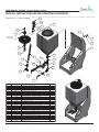
Model ALX-RDS | BOM
7(
12
3$57180%(5
$/;6&
$/;6&
)
)
)
)
0
0
0
0
0
0
0
0
0
3
3
3
3
3
3
3
3
3
3
3
3
3
3
3
3
'(6&5,37,21
$/;6&$/(&21',7,21(5$66<23326,7(25,(17$7,21
$/;6&$/(&21',7,21(5$66<
67$1'2));;66
1871</2&.66
:$6+(5667<3($
%2/7++&;66
-8*&2/257$*5('
$/;3803&21752//(5$66<9
6&$/($66(0%/<$/;9
-8*&2/257$**5((1
0'67$1.$66(0%/<
0'67$1.$66(0%/<
0'672:(5
0'6:$7(5$66<
$,55(*8/$725$66<0'6
48,&.),7(/%2:137;78%(
48,&.),77-2,1732/<352
48,&.(;+$8679$/9(48,&.),7
48,&.),7(/%2:137;78%(
48,&.),7<
48,&.),767(0(/%2:;
6+872))9$/9(78%(33
&$0&283/(5)(0$/(;%$5%
&$0&283/(50$/(;3,3(
48,&.),75('8&(57((;;
3,3(+(;1,33/(32/<
48,&.),7(/%2:
3,3((/%2:32/<
48,&.),73/8*
*$6.(79,721&$0&283/(5
+86.<*5$&23803
81/(6627+(5:,6(63(&,),('
',0(16,216$5(,1,1&+(6
72/(5$1&(6
)5$&7,21$/ $1*8/$50$&+ %(1' 7:23/$&('(&,0$/ 7+5((3/$&('(&,0$/ 7+(,1)250$7,21&217$,1('
,17+,6'5$:,1*,67+(62/(
3523(57<2)&/($1/2*,;
$1<5(352'8&7,21,13$57
25$6$:+2/(:,7+2877+(
:5,77(13(50,66,212)
&/($1/2*,;,6352+,%,7('
'5$:1%<$=,(*(5
),1,6+
'$7(
USER MANUAL (MODEL: ALX-RDS) Page 48 of 58
35235,(7$5<$1'&21),'(17,$/
0$7(5,$/
:(,*+7/%
47<
127('(%855$1'%5($.
$//6+$53('*(6
7,7/($/;0'65(9
,7(0180%(5
6&$/(
6+((72)
11/01/2014
NO.
USER MANUAL: ALX-RDS - Remote Delivery System
READ ALL INSTRUCTIONS BEFORE OPERATING EQUIPMENT
Model ALX-RDS-MAN-5
NOTE:
LEFT SIDE ORIENTATION SHOWN.
12
6
PART NUMBER DESC
1
F1056
WAS
2
F1127
BOLT
3
F1128
WAS
4
M1321
MAN
5
P1136
PIPE
6
P1137
PIPE
7
P1145
1/2 N
8
P1216
QUIC
9
P1318
CHEC
10
P1359
QUIC
11
P1421
PIPE
12
P1499
PIPE
13
P1502
CHEC
9
13
5
2
11
3
1
4
10
8
7
UNLESS OTHERWISE SPECIFIED:
NO.
SHOWN.
6
PART NUMBER DESCRIPTION
1
F1056
WASHER 1/4 SS TYPE A
2
F1127
BOLT HHC 1/4-20 X 2-1/4 X 3/4 SS
3
F1128
WASHER SPLIT LOCK 1/4 SS
4
M1321
MANIFOLD SHORT
5
P1136
PIPE HEX NIPPLE 1/2 X 1/2 POLY
6
P1137
PIPE ADAPTER HOSE BARB 1/2 X 1/2 POLY
7
P1145
1/2 NPT PLASTIC DIAPHRAGM VALVE
8
P1216
QUICK FIT ADAPTER 1/8" NPT X 1/4" TUBE
9
P1318
10
P1359
QUICK FIT ADAPTER 1/2" NPT X 3/8" TUBE
1
11
P1421
PIPE ADAPTER HOSE BARB 1/2 X 90 POLY
1
12
P1499
PIPE ELBOW STREET 1/2" POLY
1
13
P1502
CHECK VALVE 1/2"F X 1/2"M 0.5# HASTELLOY/VITON
1
4
5 CHECK VALVE 1/2"F X 1/2"M 3# HASTELLOY/VITON
9
USER MANUAL (MODEL: ALX-RDS) Page 49 of 58
5
PROPRIETARY
THE INFORM
IN THIS DRA
PROPERTY
ANY REPRO
OR AS A W
WRITTEN PE
CLEAN-LOG
DIMENSIONS ARE IN INCHES
QTY.
TOLERANCES:
FRACTIONAL
1/16"
2
ANGULAR: MACH .5 BEND 2
2
TWO PLACE DECIMAL
.015"
THREE
2 PLACE DECIMAL .005"
MATERIAL
1
Material <not specified>
1
FINISH
5
WEIGHT
1 (LB.)
1
5
DRAWN B
DATE: 10
NOTE: DE
ALL SHAR
1.98
3
11/01/2014
USER MANUAL: ALX-RDS - Remote Delivery System
READ ALL INSTRUCTIONS BEFORE OPERATING EQUIPMENT
Model ALX-RDS-DEST-55(9,6,216
| Parts Callout
5(9
'(6&5,37,21
$''('&$0/2&.),77,1*672:$7(5)/86+9$/9(),;('
:$7(5)/86+9$/9(25,(17$7,215(029('0$18$/
29(55,'('(67,1$7,219$/9($77232)0$1,)2/'
'$7(
12
)
)
)
)
0
0
0
3
3
3
3
3
3
3
3
3
3
3
3
3
3
3
3
3$57180%
81/(6627+(5:,6(63(&,),('
',0(16,216$5(,1,1&+(6
72/(5$1&(6
)5$&7,21$/ $1*8/$50$&+ %(1' 7:23/$&('(&,0$/ 7+5((3/$&('(&,0$/ '5$:1%<$=,(
),1,6+
'$7(
:(,*+7/%
7+(,1)250$7,21&2
,17+,6'5$:,1*,67+
3523(57<2)&/($1
$1<5(352'8&7,21
25$6$:+2/(:,7+
:5,77(13(50,66,212
&/($1/2*,;,6352+
0$7(5,$/
0DWHULDOQRWVSHFLILHG!
USER MANUAL (MODEL: ALX-RDS) Page 50 of 58
35235,(7$5<$1'&21
127('(%855$1'
$//6+$53('*(6
11/01/2014
USER MANUAL: ALX-RDS - Remote Delivery System
READ ALL INSTRUCTIONS BEFORE OPERATING EQUIPMENT
Model ALX-RDS-DEST-5 | BOM
12
3$57180%(5 '(6&5,37,21
47<
)
%2/7++&;66
)
1871</2&.66
)
:$6+(5667<3($
)
:$6+(563/,7/2&.66
0
0$1,)2/'325732/<352
0
$/;3803&21752//(5$66<9
0
$/;3&%/(('),77,1*
3
48,&.),7(/%2:137;78%(
3
48,&.),7$'$37(5137;78%(
3
48,&.),7(/%2:137;78%(
3
48,&.),7(/%2:137;78%(
3
9$/9($,52339&
3
&+(&.9$/9(+$67(//2<9,721
3
&$0&283/(5)(0$/(;%$5%
3
&$0&283/(50$/(;3,3(
3
3,3((/%2:675((732/<
3
48,&.),75('8&(57((;;
3
3,3($'$37(5+26(%$5%;;33
3
3,3($'$37(5+26(%$5%;33
3
3,3(1,33/(;32/<
3
3,3(+(;1,33/(32/<
3
3,3(3/8*32/<
3
*$6.(79,721&$0&283/(5
USER MANUAL
(MODEL: ALX-RDS) Page 51 of 58
27+(5:,6(63(&,),('
35235,(7$5<$1'&21),'(17,$/
7+(,1)250$7,21&217$,1('
11/01/2014
(9
USER MANUAL: ALX-RDS - Remote Delivery System
READ ALL INSTRUCTIONS BEFORE OPERATING EQUIPMENT
5(9,6,216
'(6&5,37,21
'$7(
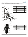
Model
M1471 | Tank Assembly
83'$7('0725(9
&+$1*('6<67(0'(6,*172,1&25325$7($',63(16( 0$1,)2/'7$1./,'$1'),//:$1'
,1&/8'('
:,7+7$1.
81/(6627+(5:,6(63(&,),('
12
3$57180%(5
)
)
)
0
0
0
3
3
3
3
3
3
3
3
3
3
3
3
3
3
3
3
3
3
3
3
',0(16,216$5(,1,1&+(6
72/(5$1&(6
)5$&7,21$/ $1*8/$50$&+ %(1' 7:23/$&('(&,0$/ 47<
7+5((3/$&('(&,0$/
'(6&5,37,21
%2/7++&;66
0$7(5,$/
:$6+(5667<3($
0DWHULDOQRWVSHFLILHG!
:$6+(563/,7/2&.66
),1,6+
6&$/(75$<7$1.+2/'(5$66<
:(,*+7/%
7$1.:$6+,1*12==/(
),//:$1'*$//217$1.
3,3(7((32/<
3,3(+(;1,33/(;32/<
48,&.),7(/%2:137;78%(
&+(&.9$/9();0+$67(//2<9,721
48,&.),7$'$37(5137;78%(
9$/9($,52339&
J32/<5,16(7$1.6/23(%27720
&$0&283/(5)(0$/(;%$5%
&$0&283/(50$/(;3,3(
3,3((/%2:675((732/<
3,3(5('8&(51,33/(;32/<
9$/9(%$//39&0$/()(0$/(
3,3($'$37(5+26(%$5%137;33
3,3(+(;1,33/(32/<
*$6.(79,721&$0&283/(5
&$0&283/(50$/(;137
&$0&283/(5)(0$/(;%$5%
%8/.+($'7$1.),77,1*137
&+(&.9$/9(0;0+$67(//2<9,721
3,3(7((32/<
5(9,6,216
5(9
'(6&5,37,21
'$7(
83'$7('0725(9
1
&+$1*('6<67(0'(6,*172,1&25325$7($',63(16(
0$1,)2/'7$1./,'$1'),//:$1'
35235,(7$5<$1'&21),'(17,$/
7+(,1)250$7,21&217$,1('
,17+,6'5$:,1*,67+(62/(
3523(57<2)&/($1/2*,;
$1<5(352'8&7,21,13$57
25$6$:+2/(:,7+2877+(
:5,77(13(50,66,212)
&/($1/2*,;,6352+,%,7('
'5$:1%<$=,(*(5
7,7/(0'67$1.$66(0%/<5(9
'$7(
,7(0180%(50(;3/2'('
127('(%855$1'%5($.
$//6+$53('*(6
6&$/(
6+((72)
81/(6627+(5:,6(63
',0(16,216$5(,1,1&
72/(5$1&(6
)5$&7,21$/ $1*8/$50$&+ 7:23/$&('(&,0$/
7+5((3/$&('(&,0$/
0$7(5,$/
0DWHULDOQRWVSH
USER MANUAL (MODEL: ALX-RDS) Page 52 of 58
11/01/2014
),1,6+
:(,*+7/%
REVISIONS
EV.
102
NO.
DESCRIPTION
DATE
CHANGED FROM HOSE BARB TO 3/8" QUICK-FIT 2
PLACES.
10/28/2014
USER MANUAL: ALX-RDS - Remote Delivery System
PART NUMBER DESCRIPTION
1
P1140
PIPE TEE 1/2 SS
2
P1198
PIPE ELBOW 1/2 X 90 SS
3
P1273
QUICK FIT ADAPTER 1/2" NPT x 1
4
P1359
QUICK FIT ADAPTER 1/2" NPT X 3
5
P1397
STRAINER Y 1/2" NPT 316SS 100 M
6
P1398
PRESSURE REGULATOR WATER 1
7
P1399
PRESSURE GAUGE WRG14
8
P1407
PIPE ADAPTER HOSE BARB 1/2" N
BARB X 90 PPQTY.
READ ALL INSTRUCTIONS BEFORE OPERATING EQUIPMENT
Models M1489 & M1492 | Water & Air Regulators
DATE
ICK-FIT 2
NO.
4 102
1
P1140
2
P1198
P1408
PIPE TEE 1/2 SS 9
10
PIPE ELBOW 1/2 X 90 SS P1409
3
P1273
QUICK FIT ADAPTER 1/2" NPT x 1/2" TUBE
1
4
P1359
QUICK FIT ADAPTER 1/2" NPT X 3/8" TUBE
2
5
P1397
STRAINER Y 1/2" NPT 316SS 100 MICRON
1
6
P1398
PRESSURE REGULATOR WATER 1/2" SS
1
7
P1399
PRESSURE GAUGE WRG14
1
8
P1407
PIPE ADAPTER HOSE BARB 1/2" NPT X 3/4"
BARB X 90 PP
2
9
P1408
PIPE NIPPLE 1/2 X 2 SS
3
10
P1409
PIPE NIPPLE 1/2 X 3 SS
2
1
10/28/2014
4 102
10
9
7
1
6
PART NUMBER DESCRIPTION
PIPE NIPPLE 1/23 X 2 SS
PIPE NIPPLE 1/21 X 3 SS
4 102
1
9
8
5
9
107
3
6
9
2
9
UNLESS OTHERWISE SPECIFIED:
1
5
8
NO.
1
2
3
1
3
4
DIMENSIONS ARE IN INCHES
TOLERANCES:
PART NUMBER
DESCRIPTION 1/16"
FRACTIONAL
F1075 ANGULAR:
SCREW SELF
TAP 10-16
SS
MACH
.5X 1/2BEND
2
M1521TWOREGULATOR
BRACKET R38 .015"
PLACE DECIMAL
P1207 THREE
PIPE
HEX PLUG
1/8 POLY
PLACE
DECIMAL
.005"
P1418
P1419
6
P1483
2
4
5
9
1
UNLESS OTHERWISE SPECIFIED:
8
DIMENSIONS ARE IN INCHES
TOLERANCES:
FRACTIONAL 1/16"
ANGULAR: MACH .5 BEND 2
TWO PLACE DECIMAL
.015"
THREE PLACE DECIMAL
.005"
1
MATERIAL
6
Material <not specified>
4
FINISH
WEIGHT (LB.)
4
5
REGULATOR AIR 3/8"
Material
<not0-100psi
specified>
PRESSURE GAUGE
1/4 NPT
FINISHNUT R38 REGULATOR MOUNTING
P1484
7
7
QUICK FIT 3/8 NPT X 1/2 TUBE
MATERIAL
5
NO.
1
2
DRAWN
BY: A. ZIEGER
1
2
M1521
IN THIS DRAWING IS THE SOLE
4
PROPERTY
OFP1418
CLEAN-LOGIX. QUICK FIT 3/8 NPT X 1/2 TUBE
ANY REPRODUCTION IN PART
OR
WITHOUT THEREGULATOR AIR 3/8"
5 AS A WHOLE
P1419
WRITTEN PERMISSION OF
CLEAN-LOGIX
IS PROHIBITED. PRESSURE GAUGE 0-100psi 1/4
6
P1483
1
2
1
NPT
1
TITLE: MDS WATER ASSY REV102
DATE: 10/28/2014
ITEM NUMBER:
SCALE: 1:4
PROPRIETARY AND CONFIDENTIAL!
THE INFORMATION CONTAINED
IN THIS DRAWING IS THE SOLE
PROPERTY OF CLEAN-LOGIX.
ANY REPRODUCTION IN PART
OR AS A WHOLE WITHOUT THE
WRITTEN PERMISSION OF
CLEAN-LOGIX IS PROHIBITED.
MATERIAL
DRAWN BY: A. ZIEGER
FINISH
DATE: 5/20/2014
NOTE: DEBURR AND BREAK
ALL SHARP EDGES!
M1489
1
DRAWN
BY:P1484
A. ZIEGER NUT R38 REGULATOR MOUNTING
7
DIMENSIONS ARE IN INCHES
TOLERANCES:
FRACTIONAL 1/16"
ANGULAR: MACH .5 BEND 2
TWO PLACE DECIMAL
.015"
THREE PLACE DECIMAL
.005"
0.90
QTY.
SCALE: 1:4
2
3 INFORMATION
P1207
PIPE HEX PLUG 1/8 POLY
THE
CONTAINED
UNLESS OTHERWISE SPECIFIED:
Material <not specified>
ITEM NUMBER:
2
3 REGULATOR BRACKET R38
2
USER MANUAL (MODEL: ALX-RDS) Page 53 of 58
TITLE: MDS WATER ASSY R
1
DATE:
10/28/2014
1
PROPRIETARY AND CONFIDENTIAL!
3
WEIGHT (LB.)
THE INFORMATION CONTAINED
IN THIS DRAWING IS THE SOLE
PROPERTY OF CLEAN-LOGIX.
QTY.
ANY
REPRODUCTION IN PART
OR 2AS A WHOLE WITHOUT THE
WRITTEN
PERMISSION OF
1
CLEAN-LOGIX
IS PROHIBITED.
1
DEBURR AND BREAK
PART
NUMBER
DESCRIPTION NOTE:
WEIGHT
(LB.)
ALL SHARP EDGES!
4.23
F1075
SCREW SELF TAP 10-16 X 1/2 SS
NOTE: DEBURR AND BREAK
ALL SHARP EDGES!
2
4.23
PROPRIETARY AND CONFIDENTIAL!
1
M1489
SHEET 1 OF 1
1
11/01/2014
TITLE: AIR REGULATOR ASSY MDS REV101
ITEM NUMBER:
SCALE: 2:3
M1492
SHEET 1 OF 1
S
DISPENSE INSTRUCTIONS (MODEL: ALX-MDS) Page 1 of 2
Ϯ͘ŶƚĞƌƚŚĞĐŽĚĞĨŽƌƚŚĞĂƉƉůŝĐĂƟŽŶLJŽƵǁĂŶƚƚŽĚŝƐƉĞŶƐĞ͘
ĚĞƐĐƌŝƉƟŽŶǁŝůůĐŽŵĞƵƉƚŽĐŽŶĮƌŵƚŚĞĨŽƌŵƵůĂ͘
Home Screen: Type passcode to login
ENTER
09/12/2014
Passcode Entered /ŶĐŽƌƌĞĐƚůLJ
ϯ͘WƌĞƐƐEdZŽƌ^dZdƚŽĐŽŶƟŶƵĞ͘
Passcode Entered ŽƌƌĞĐƚůLJ
ϭ͘dLJƉĞŝŶLJŽƵƌϰĚŝŐŝƚƵƐĞƌĐŽĚĞƚŽůŽŐŝŶ͘ĐŽƌƌĞĐƚƉĂƐƐĐŽĚĞǁŝůůďƌŝŶŐLJŽƵƚŽƚŚĞWƌĞͲŝƐƉĞŶƐĞƐĐƌĞĞŶ͘/ŶĐŽƌƌĞĐƚĐŽĚĞƐǁŝůůĂƉƉĞĂƌŝŶZ.
/ĨLJŽƵƌĐŽĚĞŝƐĞŶƚĞƌĞĚŝŶĐŽƌƌĞĐƚůLJ͕ƉƌĞƐƐ>Zͬ>ďƵƩŽŶƚŽŐŽďĂĐŬ͘
>ĞĂǀĞDĂŝŶWŽǁĞƌKEĂƚĂůůƟŵĞƐ
>tz^tZd,WZKWZWW͛^;/E>h/E'&^,/>Ϳt,/>/^WE^/E',D/>^
>E>K'/yDDZEK^/E'^z^dD/^WE^/E'/E^dZhd/KE^
Printable Instructions
Dispensing Instructions (English)
DISPENSE INSTRUCTIONS (MODEL: ALX-MDS) Page 2 of 2
ϱ͘dŚĞĂƉƉůŝĐĂƟŽŶǁŝůůďĞŐŝŶƚŽĚŝƐƉĞŶƐĞ͘
KEKd>sd,hE/dhEddE
t,/>/d/^/^WE^/E',D/>͊
ϰ͘WƌĞƐƐ^dZdĂŐĂŝŶƚŽďĞŐŝŶƚŚĞĚŝƐƉĞŶƐĞ͘
/DWKZdEd͗/&WW>/d/KEE^dK
^dKWWhZ/E'/^WE^͕WZ^^^dKW
ϭ͘dKh,d,:h'
Ϯ͘dKh,d,^>
ϯ͘dKh,KZ>E'/E^d
d,dKtZ
KEKdKEzK&d,&K>>Kt/E'
t,/>/^WE^/^/EWZK^^͗
09/12/2014
ϲ͘ KŶĐĞ ƚŚĞ ĂƉƉůŝĐĂƟŽŶ ŝƐ ĮŶŝƐŚĞĚ͕ ƉƌĞƐƐ
^dKWƚŽƌĞƚƵƌŶƚŽƚŚĞŚŽŵĞƐĐƌĞĞŶ͕ŽƌƉƌĞƐƐ
^dZdƚŽĚŝƐƉĞŶƐĞĂŶŽƚŚĞƌĂƉƉůŝĐĂƟŽŶ͘
>tz^tZd,WZKWZWW͛^;/E>h/E'&^,/>Ϳt,/>/^WE^/E',D/>^
>E>K'/yDDZEK^/E'^z^dD/^WE^/E'/E^dZhd/KE^
DISPENSE INSTRUCTIONS (MODEL: ALX-MDS) Page 1 of 2
ENTER
09/12/2014
Código de Acceso Introducido Incorrectamente
3. WƵůƐĞEdZŽ^dZdƉĂƌĂĐŽŶƟŶƵĂƌ.
Código de Acceso Introducido Correctamente
2. Escriba el código para la fórmula que quiere dispensar.
hŶĂĚĞƐĐƌŝƉĐŝſŶƐĞǀĂŶĂƉůĂŶƚĞĂƌƉĂƌĂĐŽŶĮƌŵĂƌůĂĨſƌŵƵůĂ͘
Pantalla de Inicio: Tipo de Contraseña
1. Escriba su código de usuario de 4 dígitos que entrar. Si se ha introducido correctamente el código, se le llevará a la siguiente pantalla. Si se introduce el
código de forma incorrecta, el asteriscos se volverá ROJO. Si se introduce el código de forma incorrecta, pulse la tecla CLR / DEL para borrar los números
erróneos, y vuelva a intentarlo.
Deje el Interruptor de Alimentación Principal en Todo Momento
CHEMICAL ALLOCATION LOGIX INSTRUCCIONES
SIEMPRE USAR LA ROPA ADECUADA (INCLUYENDO LA CARETA)
CUANDO SE DISTRIBUYE PRODUCTOS QUÍMICOS
Dispensing Instructions (Spanish)
DISPENSE INSTRUCTIONS (MODEL: ALX-MDS) Page 2 of 2
5. Aplicación comenzará a dispensar.
ϰ͘WƌĞƐŝŽŶĞ^dZdƉĂƌĂĐŽŶĮƌŵĂƌůĂĚŝƐƉĞŶƐĂĐŝſŶ͘
IMPORTANTE: SI SE NECESITA
TERMINAR, PULSE “STOP”
NO TOQUE EL JARRA,
LA ESCALA, O LA TORRE,
DURANTE LA
DISPENSACIÓN
09/12/2014
6. Cuando haya terminado de la dispensación,
pulse STOP para cerrar el sesión.
CHEMICAL ALLOCATION LOGIX INSTRUCCIONES
SIEMPRE USAR LA ROPA ADECUADA (INCLUYENDO LA CARETA)
CUANDO SE DISTRIBUYE PRODUCTOS QUÍMICOS
Manually Emptying Tanks
MANUALLY REMOVING CHEMICAL FROM THE TANKS
ALWAYS WEAR THE PROPER PPE’S (INCLUDING
FACESHIELD) WHILE DISPENSING CHEMICALS
Read through the following instructions if chemical
becomes trapped in the 10 gallon tank.
Point the discharge hose on the bottom of the tank into a
jug or drain. Chemical will flow out from here.
Open the ball valve on the bottom of the 10 gallon tank.
Once this is opened, chemical will begin to flow out.
Once all of the chemical is removed from the tank, close
the valve.
Prime the pump for water on that manifold to rinse the
tank and flush the manifold. See Page 21 for instructions
on priming the pump for water.
After the tank has been rinsed and the manifold has been
flushed, open the ball valve on the bottom of the 10 gallon
tank again to drain the water out the discharge line.
Close the valve when completed.
Ensure that the ball valve is closed before dispensing,
otherwise chemical will leak out of the tank when a
dispense is run!