1
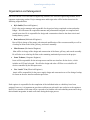
System Design and
Project Plan
PEZ (Pills EZ) Dispenser
October 12, 2010
Ben Anderson
Kyle Smith
Matt Strasser
Jason Terhune
Yao “Annie” Yao
PEZ
System Design and
Project Plan
System Design and Project Plan
···
Table of Contents
System Design ………………………………………………………….……………… 3
Background ……………………………….………………………………………. 4
System Overview …………………………………………………………………. 4
Block Diagram ………………………………………………………………...….. 5
Functional Description of Blocks ……………………………………………...…. 6
Project Plan ………………………………………………...…………….……………. 9
Organization and Management……………………...……………………….….....10
Work Breakdown Structure (Fall) …………………………...……………..…….11
Work Breakdown Structure (Spring) ………………………..….……….………. 12
Budget ………………………………………………………….…..…….……… 13
Fall Gantt Chart …………….……………………………….…...………………. 14
Spring Gantt Chart …………………………………………………………..…… 15
Fall Network Diagram ………………..………………………………………….. 16
Spring Network Diagram ……………………………………….….…………….. 17
Appendices ………………………………………………...…..……………………… 18
System Requirements Specification ….……………….…………………...…….. 19
2
System Design and Project Plan
···
System Design
3
System Design and Project Plan
···
System Design
PEZ (Pills EZ) Dispenser
Background
Presently, many people are dependent upon medications in their daily lives. An increasing
number, especially the elderly, are required to take multiple different types of medications of varying
dosages at different times throughout the day. This can become a complicated procedure for anyone,
causing missed doses, incorrect doses, and potentially life threatening mistakes. Medication works best
when taken on a routine schedule at the proper dosage. Although, medicine dispensing machines that
can solve these problems currently exist, they can range upwards of twelve hundred dollars. Clearly,
the average household cannot afford this indispensable luxury. Based on this situation, a user friendly,
affordable, semi-compact device to dispense medicine at home will be developed.
System Overview
The PEZ Dispenser prototype will attempt to simplify the medication dosing process for the
average customer. The correct dosage of medication will be dispensed throughout the day based on
user determined specifications entered via keypad. The user will be prompted to take medications
throughout the day by an alarm with an audible range similar to that of an average bedside alarm clock.
The interior of the dispenser, which can be accessed upon unlocking the lid, will hold a circular,
rotating tray on which will be eleven individual containers. It has been determined through research1
that the average individual takes no more than ten different types of medication. Therefore, up to ten of
these containers can be filled by the user with the desired medication. The eleventh container will be
used to dispense medication. The correct amount of medication will be obtained through a vacuum
system by which individual pills will be lifted from their containers and transported to the dispensing
container. The central processing unit, or the microprocessor, will store all information needed to
display a clock, sound an alarm, and dispense a dose of medication. The dispenser will be powered by
a standard 120V AC, 60Hz power supply. In case of emergency, the dispenser will be equipped with a
back-up battery which will provide at least 12 hours of reserve power.
4
System Design and Project Plan
···
Block Diagram
5
System Design and Project Plan
···
Functional Description of Blocks
Power Supply
The power supply system receives 110 VAC from a wall outlet. It then steps down the voltage and
current to the correct magnitude for each of the subsystems.
Input:
110 VAC, 60Hz Grounded
Output: To microprocessor – 5 VDC at 300 mA
To alarm – ±15 VDC at 20 mA
To keypad – 12 VDC at 20mA
To LCD – 12 VDC at 50mA
To pill tray motor – 12 VDC at 600 mA±200 mA
To vacuum nozzle control motor – 12 VDC at 600 mA ± 200 mA
To vacuum – 110 VAC, 60Hz (direct from wall)
Microprocessor
The microprocessor will store all information needed to display a clock, sound an alarm, and dispense a
dose of medication. The microprocessor will interface with an alpha/numeric keypad, LCD (Liquid
Crystal Display), alarm components, vacuum circuitry, and the motor control circuitry. A user will be
able enter all information needed via the keypad. The clock display and all prompted information
needed from program will be displayed via LCD. The appropriate signals will be sent to control the
motors motions. Also, the vacuum control circuitry will be sent a five volt digital signal to activate the
vacuum.
Input:
Power 5V DC at max of 300 mA
Digital signals from Keypad 0 to 5V at 0 to 20mA
Output: Digital signal to alarm circuitry – 0 to 5V DC at 0 to 25 mA
Digital signal to LCD – 0 to 5V DC at 0 to 25 mA
Digital signal to keypad – 0 to 5V DC at 0 to 25 mA
Digital signal to vacuum – 0 to 5V DC at 0 to 25 mA
Digital signal to motor control circuit – 0 to 5V DC at 0 to 25 mA
Input/Output System:
LCD
The user will be able to view any stored data pertaining to the alarms set, medications stored, and
dosages entered. The LCD will display the current time along with a number of messages to the user.
These messages include things such as, setting a user pin, questions about entering new medication
data, prompting visually when medication is ready for removal, and setting the clock.
6
System Design and Project Plan
···
Input:
Output:
Power 0 to 5V DC at max of 200mA
Digital Signals from Microprocessor 0 to 5V DC at 0 to 25mA
Text to viewing area.
Keypad
When prompted, or if the user needs to interact with PEZ, the user will enter information via keypad.
The keypad will be alpha/numeric and send all digital signals to the microprocessor for decoding and
storage.
Input:
Output:
Power 0 to 5V DC at max of 20mA
Digital Signals from Microprocessor 0 to 5V DC at 0 to 25mA
Digital signals to microprocessor 0 to 5V at 0 to 20mA
Alarm
The alarm will sound indicating a dose is scheduled to be taken. The alarm will be audible at a
minimum of 80 dB and a tone of approximately 1000 Hz.
Input:
Power 0 to 12V DC at 50mA
Output: > 80 dB Tone
Pill Tray/Motor
The pill tray will contain the user’s pill prescriptions. It will hold up to ten different pill types, and it
will be capable of holding up to 90 1.0 gram pills. A motor having an output torque in the range of
0.15-0.3 N-m will be sufficient to rotate the tray. The motor will rotate the tray through the necessary
angle so that the prescribed pill’s bin will be located on the suction nozzle assembly’s axis of
translation.
Input:
12 VDC at 600 mA±200 mA
Output: Correct pill bin is positioned on the nozzle assembly’s axis of
translation.
Vacuum
The vacuum will provide enough suction to lift and hold pills of various masses, ranging from 10 mg to
1.0 g. The necessary force provided by the vacuum, therefore, is equivalent to the force needed to
overcome the force of gravity on a 1.0 g pill, 0.00981 N.
Input:
110 VAC, 60Hz
Output: Suction
7
System Design and Project Plan
···
Nozzle Assembly/Motor
The nozzle assembly will translate the suction tip of the vacuum hose into the pill bin directly below it,
allowing it to make contact with each pill and affix to it. The nozzle will be selected such that small
pills or pieces of pills cannot be sucked inside. The torque requirements for the motor to drive the
assembly have yet to be determined.
12 VDC at 600 mA ± 200 mA
Output: Vertical translation of the vacuum’s nozzle
Input:
Frame/Encasement
The encasement will provide protection for the components of the dispenser, and the frame will provide
sufficient strength to support the system and allow for transportation. The encasement will have a
locking door which will allow access to the pill tray in the event that power cannot be supplied. The
dimensions will be in the range of 41 cm x 41 cm x 41 cm (16 in x 16 in x 16 in) to 77 cm x 77 cm x 77
cm (30 in x 30 in x 30 in).
Input:
None
Output: None
8
System Design and Project Plan
···
Project Plan
9
System Design and Project Plan
···
Organization and Management
Our team consists of two mechanical engineering students, two electrical engineering students, and a
computer engineering student. Project management and design tasks will be broken down into the
following responsibilities:
·
Kyle Smith (Electrical Engineer)
Kyle is the project manager and responsible for the project being completed on time and under
budget. He will ensure the required documents and presentations assigned are completed and
turned in on time. He is responsible for design and construction related to the alarm circuit and
backup battery system.
·
Ben Anderson (Mechanical Engineer)
Ben will be in charge of the proper selection and modification of the vacuum assembly as well as
a backup for Matt on the frame, pill tray, and nozzle assembly.
·
Matt Strasser (Mechanical Engineer)
Matt will be in charge of the design and construction of the frame, pill tray, and nozzle assembly.
He will also act as a backup for Ben on the remaining mechanical processes in the project.
·
Jason Terhune (Computer Engineer)
Jason will be responsible for the microprocessor and the user interface for the device, which
includes an LCD and a keypad. He will also design and order a PCB to act as a hub for all
devices controlled by the microprocessor.
·
Yao “Annie” Yao (Electrical Engineer)
Annie will be responsible for the power supply design and construction as well as being a backup
for Jason on the user interface and microprocessor.
Each engineer is responsible for the completion of the individual tasks to which they have been
assigned, however, it is important to note that work done on each task is not exclusive to the engineers
listed. Every member of the team will be expected to be familiar with each other’s systems and to keep
their ultimate integration in mind at all times during the design process.
10
System Design and Project Plan
···
Work Breakdown Structure (Fall)
ID
F 1.0
Task Name
Project Selection
F 2.0
Preliminary
System Design
Requirements
Specification
System Design
and Project Plan
Report
F 3.0
F 4.0
F 4.1
F 4.2
F 5.0
F 5.1
F 5.2
F 5.3
Presentation
Mechanical
Systems Design
Pill Tray
Assembly/Motor
Vacuum System
Deliverables/Checkpoints
Project confirmation
Duration
8/30-9/7
People
All
Choose best solutions and apply them
9/7-9/28
All
Document that sets the quantitative
requirements for the project
Breakdown of design and build process
and detailed scheduling
Write detailed report regarding the
above ideas
Present the ideas to faculty
Detailed design of each mechanical
subsystem
Holds pills and uses motor to rotate tray
Written document
9/10-9/28
All
Written document and formal
presentation
Written document
9/28-10/14
All
9/28-10/12
All
PowerPoint and verbal presentation
SolidWorks models, analysis, data
sheets, calculations, etc.
SolidWorks model, analysis,
calculations, and motor data sheet
Calculations and testing
10/8-10/14
9/28-11/5
SolidWorks model, analysis,
calculations, and motor data sheet
SolidWorks model and dimension
calculations
Electrical schematic, analysis, and data
sheets
Electrical schematic, analysis, and
calculations
Electrical schematic, analysis, and
calculations
Power consumption calculations
10/5-10/26
All
Ben,
Matt
Matt,
Ben
Ben,
Matt
Matt,
Ben
Matt,
Ben
Jason,
Kyle
Annie,
Kyle
Kyle,
Annie
Kyle,
Annie
Kyle,
Annie
Retrieves pills from chambers
F 9.1
I/O System
Design
LCD Screen
Translates vertically to retrieve pills from
chambers
Encapsulates all components of the
project
Microprocessor selection and mounting
solutions
Provides power from the wall to all
subcomponents of the system
Provides a 12-hour alternate power
supply when wall power is unavailable
Estimate power draw from all subcomponents
Research best choice for battery
chemistry to meet power consumption
and size requirements
Allows user to input, view pill
information, and set alarms
Displays vital information to the user(s)
F 9.2
Keypad
Allows the user(s) to input information
F 9.3
Alarm System
F 10.0
System Analysis
F 11.0
F 11.1
F 11.2
Final Design
Report/
Presentation
Build Mock-up
F 12.0
Documentation
F 13.0
Project
Management
Audibly alerts the user(s) when it is time
for a dose
Ensure that individual parts will integrate
into the system as a whole
Final system and sub-function design
Write detailed report regarding the
above ideas and present ideas to faculty
Build a non-functioning physical
representation of the system
Keep records of all design work,
research, and tests
Supervise the completion of project goals
on time and within budget
F 5.4
F 6.0
F 7.0
F 8.0
F 8.1
F 8.2
F 9.0
Vacuum Nozzle
Assembly/Motor
Frame Design
Description
Make a final decision on which project to
pursue
Basic design of what system will do
Microprocessor
Selection
Power Supply
Selection
Battery Backup
System Design
Estimate Power
Consumption
Select Battery
Chemistry
11
Analysis, data sheets, and part
selection
9/28-10/19
10/1-10/15
10/26-11/5
10/6-10/11
9/28-10/19
10/1210/26
10/1210/26
10/1210/26
Electrical schematic, analysis, and
data sheets
Electrical schematic, analysis, and data
sheets
Electrical schematic, analysis, and data
sheets
Electrical schematic, analysis, and data
sheets
Finalized system design
10/13-11/8
11/9-12/6
Jason,
Annie
Jason,
Annie
Jason,
Kyle
Kyle,
Annie
All
Written document and presentation
Written document and formal
presentation
Fully-assembled structure representing
each sub-system
Documents and engineering
notebooks
Deadlines, constraints, and
specifications met
11/15-12/9
11/9-12/9
All
All
11/9-12/9
All
8/30-12/9
All
8/30-12/9
Kyle
10/1310/22
10/15-11/8
10/13-11/8
System Design and Project Plan
···
Work Breakdown Structure (Spring)
ID
S 1.0
S 1.1
S 1.2
S 1.3
S 1.4
S 1.5
Task Name
Parts Assembly
and Testing
Pill Tray and
Motor
Vacuum System
Vacuum Nozzle
and Motor
Power Supply
Description
Assemble all parts and verify that they
work correctly
Build, assemble, and test rotation of the
tray
Test system using required range of pill
types and attach to nozzle assembly
Build, assemble, and test vertical
translation
Implement and test voltage control
circuit
Backup Battery
System
I/O System
Implementation
Build and test that the battery will
power system for 12 hours
System through which the user
interfaces with the prototype
S 1.6.1
LCD Screen
S 1.6.2
Keypad
S 1.6.3
Alarm System
S 1.7
S 1.8
User Interface
Configuration
Board Etching
S 2.0
S 3.0
Programming
Project Status
S 3.1
Report
S 3.2
S 4.0
S 6.0
S 7.0
Presentation
System Frame
Assembly
System
Integration
System Testing
Finalize Prototype
S 8.0
User’s Manual
S 9.0
S 9.1
Final Project
Report
S 9.2
Presentation
Connect and test LCD screen with the
microcontroller
Create and test a keypad circuit for user
input
Build and test that alarm sounds at
programmed times
Configure the keypad and LCD to work
with programming
Design circuit boards for final system
and etch them
Write and test code for microcontroller
Description of current progress of the
project
Write detailed report regarding the
above ideas
Present the ideas to the faculty
Build frame to house all subcomponents
Compile all modules to create
prototype
Run full system test
Verify correct operation and prepare for
presentation
Describes how to use the device and
any special considerations
Final design and functioning prototype
Write detailed report regarding the
above ideas
Present project to faculty
S 10.0
Documentation
S 11.0
Project
Management
S 1.6
S 5.0
Keep records of all design work,
research, and tests
Supervise the completion of project
goals on time and within budget
12
Deliverables/Checkpoints
Working modules and test data
Duration
1/20-4/25
People
All
Functioning system of tray and motor
assembly
Functioning vacuum pill-retrieval
system
Functioning system of vacuum nozzle,
gear, and rack
Working module that steps down the
voltage and current to the correct
values
Functioning battery system
1/20-2/1
Matt,
Ben
Ben,
Matt
Ben,
Matt
Annie,
Kyle
All components built and functioning
to specifications
2/10-3/11
Working LCD screen that outputs all
text correctly at the appropriate time
Working keypad that can be used to
input information
Functioning, fully-audible alarm
2/22-3/11
Working user interface
2/22-3/11
Professional and self-made circuit
boards
Functioning system code
Report and presentation
4/11-4/25
1/20-3/11
2/15-3/10
Kyle,
Annie
Jason,
Kyle,
Annie
Jason,
Annie
Jason,
Kyle
Kyle,
Annie
Jason,
Annie
Kyle,
Annie
Jason
All
Written report
2/15-3/8
All
PowerPoint and verbal presentation
Completed frame
3/8-3/10
3/22-4/8
Assembled project and test data
3/22-4/11
All
Matt,
Ben
All
Test data
Completed prototype
4/11-4/25
4/25-5/3
All
All
Document
4/12-4/30
All
Report and presentation
Written report
4/5-5/5
4/5-5/3
All
All
PowerPoint, verbal presentation, and
demonstration
Documents and engineering
notebooks
Deadlines, constraints, and
specifications met
5/3-5/5
All
1/18-5/5
All
1/18-5/5
Kyle
2/1-2/15
2/15-3/1
1/20-2/1
2/1-2/8
2/22-3/8
2/10-2/18
System Design and Project Plan
···
Budget
Item
Motor (to rotate tray)
Tray
Motor
(for nozzle assembly)
Gear and Rack
Vacuum
Plexiglas (4’ x 8’)
tools/building materials
(for frame and enclosure)
Microprocessor
(PIC30F)
LCD
Keypad
Battery
Power Supply
Alarm
PCB
(manufactured and self-made)
Estimated Costs
Prospective Vender
Cost ($)
www.robotshop.com
www.rexart.com
www.robotshop.com
38.00
2.00
20.00
Estimate
Date
0ct.4,2010
0ct.4,2010
0ct.4,2010
www.qtcgears.com
www.virtual-ii.com
www.professionalplastics.com
Lowe’s
100.00
90.00
150.00
75.00
0ct.4,2010
0ct.4,2010
0ct.4,2010
0ct.4,2010
www.microchipdirect.com
10.00
0ct.4,2010
www.robotshop.com
www.jameco.com
www.all-battery.com
www.Amazon/spytown.com
www.Amazon.com
www.PCBexpress.com
17.95
21.95
35.00
30.00
10.00
75.00
0ct.4,2010
0ct.4,2010
0ct.4,2010
0ct.4,2010
0ct.4,2010
0ct.4,2010
Total
674.90
Contingency
325.10
Budget
1,000.00
13
Fall Gantt Chart
14
Spring Gantt Chart
15
Fall Network Diagram
16
Spring Network Diagram
17
System Design and Project Plan
···
Appendices
18
System Design and Project Plan
···
REQUIREMENTS SPECIFICATION
Background
Our team will analyze, build and test an automatic pill dispenser. This dispenser will be powered by a
120V AC, 60Hz power supply with a back-up battery to provide at least 12 hours of reserve power. The
user will easily interface with the dispenser; in return it will dispense the correct amount of pills, on
time, with the prompt of an alarm clock. The automatic pill dispenser combines microcontrollers with
mechanical technologies, allowing for one user. The machine will operate with precision (explained
further in test plan), ensuring that the correct prescription is dispensed at every instance of operation.
System Overview
According to the data released by PRIME Institute for Families USA, annual spending per elderly
person for prescription drugs grew from $559 in 1992 to $1,205 in 2000, an increase of 116 percent. By
2010, annual per person spending on drugs for the elderly is projected to reach $2,810 a year, an
increase of 133 percent over spending in 2000
(http://answers.google.com/answers/threadview/id/563761.html). This data indicates that an everincreasing number of elderly people are going to join the community of “medicine dependent people”,
and significantly greater quantities of prescription medicine will be given to people daily. As a result,
not only for the elderly people, but also for this group of people who are heavily dependent on
medication, taking pills correctly and punctually will be a growing problem. There is a product
designed to dispense medicine that has already been on the market; however, it costs $1,200. Based on
this situation, our group will research and develop an easily-manipulated device to dispense medicine
at home, and reduce the manufacturing cost of the dispenser as much as possible.
Operational Description (Draft User’s Manual)
Important Safeguards:
1. All users of the PEZ must read and understand this owner’s manual before operating the PEZ.
2. The power cord should be plugged into a 120V AC electrical outlet only.
3. If the PEZ begins to malfunction during use, immediately unplug the cord. Do not use or
attempt to repair the malfunctioning PEZ. Contact Team PEZ for further instructions.
Introduction:
To-Do: insert a brief description of the PEZ.
19
System Design and Project Plan
···
Before you use the PEZ for the first time:
1. Use inventory provided on first page of this manual to confirm all parts are present.
2. Assemble the PEZ and make sure the on/off switch is set to off. 3. Plug in the PEZ to power.
Set the clock:
1. Turn power switch to on position.
2. Details for this will be included once more research is done about the microprocessor.
Manual Entry of prescriptions or vitamins:
1. A step by step procedure will walk the user thought a process of adding medication and alarms.
Cleaning and Maintenance:
A build up residue may hinder the performance of the pill counting mechanism. For best results,
completely clean and dry all removable parts monthly or when needed. When cleaning your PEZ,
please observe the following precautions:
1. Make sure the PEZ is off and unplugged. All user data and dosage information will not be lost.
2. NEVER IMMERSE THE CORD, PLUG OR PEZ IN WATER OR OTHER LIQUID.
3. Do not use metal cleaning pads or abrasive cleaners.
Requirements
1. Will handle up to 10 different kinds of pills ranging from 10 milligrams to 1 gram.
2. No more than four kinds will have the same mass, no more than four will have the same
coating, and no more than three will have the same shape.
3. The alarm to take the dosage will sound within two seconds of the programmed time.
4. Should take no more than one minute to transport one pill from its holding chamber to the
dispensing chamber.
5. Will alert the user when it is time to take a dose of medicine.
6. Prescription information (how many of each kind of pill to be taken at a specific time of day on
certain days) can be entered manually through a user interface using a keypad and screen.
7. Will alert the user when a pill supply gets low (three days dosage left).
8. Will allow the user to access the pills by entering a secret PIN code. This applies when loading
a supply of pills or retrieving a dose of pills.
9. Will be powered by a standard 120 V, 60 Hz, AC outlet.
10. Will have a battery back-up lasting at least 12 hours.
11. Should be a table-top device that can be carried by a typical person (definition of a typical
person further explained in the test plan).
20
System Design and Project Plan
···
Design Deliverables
1.
2.
3.
4.
5.
6.
7.
8.
User Interfacing
Alarm Notifying Medication Times
User Recognition
Of Size Such that the Average Person can Lift it
User’s Manual
List of Parts and Their Prices
Schematics
Automated Pill Dispenser Compatible with 1 user
Preliminary Test Plan
To test the pill dispensing functionality of the device, we will perform the following test (spanning 12
hours each run) three times:
·
·
·
·
·
·
·
·
Plug Device into the wall for necessary power
Load the hopper with 10 different types of Pills
A user PIN will be assigned and then the pills can be placed in the machine.
Different dosing schedules including: once a day, twice a day, and three times a day, including
one or two pill doses using the LCD/Keypad interface will be tested.
An alarm will sound alerting the user that it is time to pick up a prescription and the PIN will be
entered.
Once the PIN is entered, no less than one pill per minute (checked via stopwatch) will be
dispensed until the dose has been completely dispensed.
If there is only three days worth of a pill remaining, the user will be alerted by an alarm and an
on screen message immediately following the dose retrieval that causes the amount to fall
below the three day threshold.
The system time will be checked against a digital clock/watch and will lose a maximum of two
seconds during the test.
To test the backup battery system, the above test will be run twice running only on battery power for 12
hours with the following modifications:
·
Pills and Dose Schedules will already be present in the machine
To test that the device can be carried by a typical person, the following test will be performed:
·
Five people will be chosen at random and asked to carry the device from one end of a room to
the other.
21