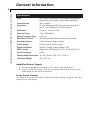
1
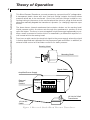
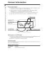
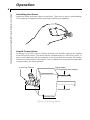
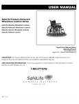
Research Grade Blood
Pressure Transducer
User's Manual
Research Grade Blood Pressure Transducer, 110 VAC/60 Hz
Research Grade Blood Pressure Transducer, 220 VAC/50 Hz
60-3002
60-3003
Table of Contents
Harvard Apparatus Research Grade Blood Pressure Transducer User’s Manual
1
SUBJECT
PAGE NO.
Warranty and Repair Information ........................2
Theory of Operation ..............................................3
General Information............................................4-5
Specifications
4
Amplifier/Power Supply
4
Front Panel Control 4
Electrical Output
5
Maintenance and Storage 5
Serial Number
5
Replacement Parts 5
Operation ............................................................6-7
Installing the Dome 6
Liquid Connections 7
Filling and Purging of Air 8
Warranty and Repair Information
Harvard Apparatus Research Grade Blood Pressure Transducer User’s Manual
2
CAUTION:
Avoid placing force on sensing button when dome is not installed.
Do not allow liquid to enter sensing head since serious damage will
result. Transducer sensing head may not survive being dropped.
Serial Numbers
All inquires concerning our product should refer to the serial number of the unit(s).
Warranty
Harvard Apparatus warranties the instrument(s) for a period of one year from date of
purchase. At its option, Harvard Apparatus will repair or replace the unit(s) if it is
found to be defective as to workmanship or material.
This warranty does not extend to damage resulting from misuse, neglect or abuse,
normal wear and tear, or accident.
This warranty extends only to the original customer purchaser.
IN NO EVENT SHALL HARVARD APPARATUS BE LIABLE FOR INCIDENTAL OR
CONSEQUENTIAL DAMAGES. Some states do not allow exclusion or limitation of
incidental or consequential damages so the above limitation or exclusion may not
apply to you. THERE ARE NO IMPLIED WARRANTIES OF MERCHANTABILITY,
OR FITNESS FOR A PARTICULAR USE, OR OF ANY OTHER NATURE. Some states
do not allow this limitation on an implied warranty, so the above limitation may not
apply to you.
If a defect arises within the one-year warranty period, promptly contact Harvard
Apparatus, Inc. 84 October Hill Road, Holliston, Massachusetts 01746-1371
using our U.S. only toll free number 1-800-272-2775 or dial (508) 893-8999. Goods
will not be accepted for return unless an RMA (returned materials authorization)
number has been issued by our customer service department. The customer is
responsible for shipping charges. Please allow a reasonable period of time for completion of repairs, replacement and return. If the unit is replaced, the replacement
unit is covered only for the remainder of the original warranty period dating from the
purchase of the original device.
This warranty gives you specific rights, and you may also have other rights which vary
from state to state.
Repair Facilities and Parts
Harvard Apparatus stocks replacement and repair parts. When ordering, please
describe parts as completely as possible, preferably using our part numbers. If practical, enclose a sample or drawing.We offer a complete reconditioning service.
CAUTION: Not for clinical use on human patients.
Theory of Operation
Harvard Apparatus Research Grade Blood Pressure Transducer User’s Manual
3
This Blood Pressure Transducer converts pressure to a proportional DC voltage value.
A transparent plastic dome with two Luer-lock fittings contains the liquid whose
pressure values are to be monitored. One of the Luer-lock fittings is used for connecting tubing to the source to be monitored and the other to purge air that would
otherwise markedly degrade the transducer’s dynamic (i.e. changing) response capabilities.
The dome has an internal membrane that contacts a button on the sensing head.
Liquid pressure within the dome acts through the membrane to produce a force
upon the button. The force, in turn, acts against a rigid flexure-spring assembly to produce a small increment of motion which is measured by a differential capacitor circuit housed within the sensing head.
From here, a cable carries the electrical signal to the power supply where the signal
is further amplified and calibrated for the purposes of gain and offset. In addition, an
external offset control will facilitate correction for static pressure.
Sensing Head
Mounting Shaft
Dome
Signal Cable
Amplifier/Power Supply
External
Offset
Control
PRESSURE
TRANSDUCER
mm Hg
OFFSET
12 Volt AC Wall
Transformer
12 Volt AC
Cable
Figure 1. Research Grade Blood Pressure Transducer
General Information
Harvard Apparatus Research Grade Blood Pressure Transducer User’s Manual
4
Specifications
Input
Two Luer-lock connectors on transparent polycarbonate
plastic dome with internal silicone rubber membrane
Internal Volume
300 µ l, approx
Compliance
14 µ l of displacement/100 mm pressure including 30.5
cm (12 in) of standard 3 mm ID vinyl tubing
Sterilization
Chemical – Alcide or Cidex
Pressure Range
-10 to +300 mmHg
Natural Frequency (Dry)
> 500 Hz
Membrane Pressure
300 mmHg without rupture and dome not installed
Overload Pressure
3,000 mmHg with dome installed
Output Voltage
Factory set at 1.0 V/100 mmHg
Digital Panel Meter
Reads in “mmHg” (output voltage x 100)
Offset Control
Adjusts from +50 mmHg (0.5 V) to -100 mmHg (1.0 V)
Carrier Frequency
2 MHz
Sensing Head Dimensions 32 x 45 x 42 mm (1.26 x 1.77 x 1.65 in)
Transducer Weight
70 g (2-1/2 oz)
Amplifier/Power Supply
a) The entire transducer is powered by a 12 volt AC wall transformer.
b) There is no ON/OFF switch. The unit can remain powered, as shown on the
digital meter, for the entire experiment.
Front Panel Control
The offset knob on the front panel is used to set a zero output voltage for any static
pressure up to 100 mmHg.
General Information
Harvard Apparatus Research Grade Blood Pressure Transducer User’s Manual
5
Electrical Output
a) Binding post are provided on the power supply for output connections. Red
is positive (+); black is negative (–) and also ground.
b) Output voltage is 1.0 V/100 mmHg pressure up to 300 mmHg. Output
impedance is 2 kΩ for direct connection to all recorders.
c) The digital panel meter, calibrated in mmHg, reads output voltage x 100.
d) High, Low, and Offset trim pots are factory calibrated. DO NOT adjust.
Binding Posts
High-Gain Trim
_
Low-Gain Trim
+
Offset Trim
To Transducer
Sensing Head
12 Volt AC Cable
Figure 2. Electrical Output
Maintenance and Storage
a) No special precautions are required other than keeping a dome installed at all
times and preventing liquids from entering the sensing head.
b) When not in use, store in a clean, dry place.
Serial Number
The serial number is located on the power supply circuit board. Refer to this number in any correspondence.
Replacement Parts
Catalog No.
Product
52-9990
Replacement Domes, pkg of 2
Operation
Harvard Apparatus Research Grade Blood Pressure Transducer User’s Manual
6
Installing the Dome
Install the dome and make liquid connections. Take care to avoid cross-threading.
The threads will engage smoothly, and finger tightening is adequate.
Liquid Connections
Orienting one of the Luer-lock fittings vertically will facilitate clearing air bubbles
when filling with liquid. The dome may be installed empty or filled with liquid. In
either case, make sure that the pressure in the dome does not exceed 300 mmHg.
Otherwise, the membrane may rupture. Once installation is complete, the membrane
is supported by the sensing button.
Signal Cable
(To Amplifier/Power Supply)
Luer-Lock Fittings
Dome
Mounting Shaft
Sensing Head
Figure 3. Sensing Head
Operation
Harvard Apparatus Research Grade Blood Pressure Transducer User’s Manual
7
Filling and Purging Air
The presence of trapped air bubbles anywhere within the liquid column will add
compliance to the system and degrade the transducer’s dynamic response capabilities. For this reason, it is recommended that the dome, tubing, and lumen be filled
with a continuous flush until all bubbles have been cleared from the system. The
dome cavity is shaped like a cone with one Luer-lock fitting at the tip (apex) and the
other to the side (lateral).
Flushing in the side and out the tip while held vertically allows the bubbles to rise.
Tapping with a finger may be required to dislodge additional bubbles. Be sure to provide sufficient opening to allow fluid to escape and thereby prevent excessive pressure build-up which may rupture the dome.
This precaution is especially important when filling an unmounted dome since the
membrane is not supported and can withstand only 300 mmHg. Thus, installing the
dome on the sensing head before filling is the safest procedure, but may not always
be possible. Close off the filling tube with a stopcock or by pinching it.