1
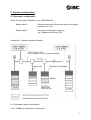
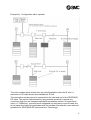
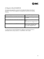
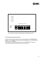
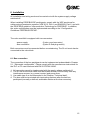
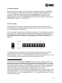
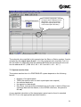
EO312-B
Instruction Manual
PROFIBUS-DP SI units
EX120-SPR1-B
EX121-SPR1-B
EX122-SPR1-B
Index
Page
1.
1.1
1.2
System overview
System description
SI unit EX12#-SPR1-B
2
2
3
2.
2.1
2.2
2.3
System configuration
Systematic configuration
PLC types and PCs
Connectable SMC solenoid valves
4
4
6
6
3.
3.1
3.2
3.3
3.4
Technical data
System technical data
PROFIBUS-DP technical data
SI unit technical data
Electromagnetic compatibility (EMC)
7
7
7
8
9
4.
4.1
4.2
4.3
Description of SI unit EX12#-SPR1-B
Description of individual components
Diagnostics display (status LEDs)
Diagnosis of Slave
10
10
11
12
5.
5.1
5.2
Settings
Address settings
Transmission speed (baud rate)
13
13
14
6.
6.1
6.2
6.3
6.4
Installation
Bus connection
Bus cable
Bus termination
Valve wiring
15
15
16
17
17
7.
7.1
18
18
7.2
7.2.1
7.2.2
7.3
Programming
Data link layer (layer 2) and PROFIBUS-DP service access points
used
Connection with PROFIBUS-DP Master
GSD File
Configuration of a PROFIBUS-DP Master
System reaction time
19
19
20
21
8.
Troubleshooting
22
9.
SMC contact addresses
24
1
1. System overview
1.1 System description
The PROFIBUS-DP is an open, manufacturer-independent field bus. This makes it
possible to use any PROFIBUS-compatible PLC or PC plug-in card as a Master for
the PROFIBUS.
PROFIBUS-DP is a deterministic, decentrally controlled field bus that uses the socalled “Delegated Token”, generally operated with one Master and is suitable for
cyclical PLC/IPC control.
The EX12#-SPR1-B SI units described here support the manufacturer-independent
PROFIBUS-DP protocol concerning IEC 61158 resp. EN 50170.
The PROFIBUS-DP protocol (decentral periphery)
32 active or passive participants can be connected, or 122 when using a maximum of
three signal amplifiers (repeaters). Different transmission speeds are possible
dependent on the max. bus length. The baud rate is automatically detected by the SI
unit and can be between 9.6 kBit/sec and 12 Mbit/sec. The transmission media used
are shielded, paired two wire cables in compliance with the above PROFIBUS-DP
standard (RS 485).
2
1.2 SI unit EX12#-SPR1-B
The SI unit makes it possible to control the SMC solenoid valves via the PROFIBUSDP protocol. All three housing types EX120, EX121 and EX122 contain identical
electronics. Only the mounting types are different.
Housing type:
EX120
EX121
EX122
Type of connection:
Direct mounting without ribbon cable,
no DIN rail mounting
DIN rail mounting with ribbon cable
Direct mounting without RC for DIN rails
for SMC valve type:
VQ, SV
SY
SY
Each Serial-Interface (SI) unit can control a maximum of 16 single solenoid or 8
double solenoid valves. Combinations of single and double solenoid valves are
possible as long as the number of coils does not exceed 16. These SI units do not
have sensor inputs.
The SI solenoid valve manifold is already wired internally. This means that the
manifold only needs to be connected to the bus line (9 pole D-Sub) and the power
supply (5 pole round connector).
The address of the bus participant can either be set via the two rotary switches on
the front of the device (hardware addressing - proposed) or via the bus protocol
(software addressing). Hardware addressing (default) is recommended in advantage
to see the adjusted slave address directly.
An internal selector switch determines which of the two address settings is permitted.
It must also be ensured that the correct GSD file which corresponds to used address
setting mode is used.
3
2. System configuration
2.1 Systematic configuration
There are two types of Master for the PROFIBUS-DP:
Master class 1:
Communication with Slaves and with control signal
networks, e.g. PLC
Master class 2:
For setup and checkout purposes,
e.g. Programming Device (PD)
Example a) Operation without repeater
*
Rt: Termination resistor combination
* for 1.5 MBit/sec, stubs must not be used!
4
Example b) Configuration with a repeater
The valve configurations shown here are interchangeable under the SI units. A
maximum of 16 output drivers are available per SI unit.
The termination resistors must be connected to the start and end of the PROFIBUSDP cable. This can be implemented by using external resistors or special bus
connectors that have an integrated switchable termination resistor. At higher baud
rates (> 1.5 MBit/sec), connectors with integrated line inductance must be used due
to the capacitive load of the participant and the resultant line reflection (see technical
guidelines for PROFIBUS-DP Interconnection Technology).
5
According to the PROFIBUS-DP standard, a maximum of three repeaters are
permitted, i.e. one repeater after every 31 Slaves. The number of repeaters affects
the maximum number of bus participants: e.g. a maximum of 30 bus participants can
be connected with one repeater and a maximum of 28 participants can be connected
with three repeaters per line.
2.2 PLC types and PCs
The SI solenoid valve manifold (SI unit + valve manifold) can be controlled by any
PLC, with an appropriate interface component as the bus master, or by a PC plug-in
card. The interface component or the PC plug-in card must be designed as a
PROFIBUS-DP standard Master.
There are a large variety of such devices or PC plug-in cards available from various
manufacturers.
2.3 Connectable SMC solenoid valves
Solenoid valves in the series VQ1000/2000 can be connected with EX120-SPR1-B
and solenoid valves in the series SY3000/5000 can be connected with
EX122/EX121-SPR1-B. These valve series, in addition to the “SI solenoid valve
manifold” design, are also available with 25 pole D-Sub connectors as electrical
input.
Order designation of the multi-connection sub-bases for solenoid valve manifolds
EX120 Type:
EX121 Type:
EX122 Type:
VV5Q#1-####SN-#-Q
SS5V#-1#S3ND-###-##
SS5Y#-45S1ND-###-##-Q
SS5Y#-45SND-###-##-Q
Note:
The letter N indicates the field bus system PROFIBUS-DP in the multi-connection
sub-base.
Important:
In the VQ series valves, the valves with the “Negative Common” resp. “Minus
Common” configuration must be used (i.e. 24 VDC is switched to the valve and the
ground is common), e.g. VQ1101N-5-Q.
Further technical data regarding the valves and valve sub-bases can be found in the
corresponding SMC product catalogues (address directory in appendix).
6
3. Technical data
3.1 System technical data
Operating temperature
Storage temperature
Relative humidity
CE marking
Degree of protection
0°C... +50°C
-20°C... +85°C
10-95% without condensation
Yes
IP 20 (DIN 40050/IEC 144)
3.2 PROFIBUS-DP technical data (as per EN 50170)
Operating mode of SI solenoid
valves
Max. number of participants
without repeater:
Maximum number of repeaters
Number of bus participants
(with three repeaters)
Transmission speed (baud rate)
and max. cable length without
repeater
(automatic baud rate detection)
Hamming distance
Cable type
Cable parameters
Impedance [Ω]
Capacitance [pF/m]
Loop resistance [Ω/km]
Core diameter [mm]
Core cross-section [mm²]
Transmission media (cable)
The SI unit is designed as a passive participant
(Slave) for the PROFIBUS-DP
32 participants (Master, Slave)
3
126 participants (Slaves). Operation as monomaster system is recommended.
Dependent on bus length and cable type A or B
used
Baud rate:
[kBaud]
12000
6000
3000
1500
500
187.5
93.75
19.2
9.6
Cable type A
[m]
100
100
100
200
400
1000
1200
1200
1200
Cable type B
[m]
Not permitted
Not permitted
Not permitted
Not permitted
200
600
1200
1200
1200
4
Cable A as per PROFIBUS-DP standard EN
50170
Cable B as per PROFIBUS-DP standard EN
19245, Part 1
Cable A
Cable B
135 to 165
100 to 130
(3.. 20MHz)
(>100kHz)
<30
<60
<110
<160
>0.64
>0.53
>0.34
>0.22
Shielded, paired two wire cable,
impedance 100 to 130Ω
Min. 0.22mm² (24 OVG), approx. 60pF/m
7
Bus structure
Connection type:
Supply voltage:
Bus connector:
Galvanic isolation
Line, closed at both ends with terminating
resistors, adapted to RS 485.
Stubs to participant as short as possible, no
branching.
5 pole round connector as per DIN 45322
9 pole D-Sub connector
50 Veff rated voltage
500Veff rated surge voltage
3.3 SI unit technical data
Supply voltage
Current consumption electronics
Current consumption load (valves)
Outputs:
- Number
- Output performance per output
- Voltage
- Polarity of outputs
- Fuse protection of outputs
Min. Slave Interval
Diagnostics functions:
- Bus fault display
- Diagnosis display
e.g. valve voltage too low
- Supply status display
+24V DC electronics
+24V DC rated voltage ± 10%
Allowable range 21.6V DC to 26.4 V DC
Separate power supply for electronics and load
(valves)
Common reference potential
Max. 70 mA at rated voltage without load
Max. 1.4 A
16
max. 2.1W
+24V DC ± 10%
Minus Common
1 micro-fuse per Byte, 2Byte
0.1 ms
LED red “BF”
LED red “DIA”
LED green “RUN”
8
3.4 Electromagnetic compatibility (EMC)
Interference
transmission
EN50081-2, 1993
EN55011 Class A Gr. 1
Resistance to
interference
Enclosure
EN50082-2, 1995
EN61000-4-2 ESD 4kV Contact/8kV air
ENV50140 HF-Field 10V/m 80... 1000 MHz
ENV50204 HF-Field 10V/m 900 MHz
B
A
A
Bus connection
EN61000-4-4 Burst 2kV
ENV50141 HF-conducted 10V, 0.15... 80 MHz
EN61000-4-4 Burst 2kV
ENV50141 HF-conducted 10V, 0.15... 80 MHz
A
A
A
A
Mains (DC)
Benchmark category A:
Benchmark category B:
Normal operating behavior within specified limits
Temporary influence of operating behavior or loss of
function that the device self-corrects.
9
4. Description of SI unit EX12#-SPR1-B
4.1 Description of individual components
18-pole ribbon cable
connector
5-pole round connector
RUN LED
DIA LED
-B
BF LED
2 rotary switches for
the station number
9-pole D-Sub socket
Sliding switch for
Address Mode
The externally visible individual components are described below.
5 pole round connector
The supply voltage for the electronics (SI unit) and for the valves (load) can both be
connected simultaneously through the connection of a 5 pole mating socket. The PS
round connector complies with the DIN 45322 standard.
Top view
3
4
2
5
1
PIN 1:
PIN 2:
PIN 3:
PIN 4:
PIN 5:
+24V DC valve voltage
0V electronics
PE, functional protective earth
+24V DC electronics
0V valve voltage
Note:
The +24V DC valve voltage and the + 24V DC supply voltage for the electronics are electrically isolated from
each other. PIN 3 (PE) must be connected with the shield connection in the mating section of the round plug
connector.
10
9 pole D-Sub socket:
The 9 pole D-Sub socket connects the SI unit with the field bus PROFIBUS-DP. The
connections of the 9 pole D-Sub socket are assigned as follows:
PIN 1
PIN 2
Shield
M24
PIN 3
PIN 4
PIN 5
PIN 6
PIN 7
RxD/TxD-P
RTS
DGND
VP
P24
PIN 8
PIN 9
RxD/TxD-N
CNTR-N
Shield/protective earth
not occupied
(reserved for 24V DC supply ground line)
Receive/transmission data-P; B line
Ready to Send
Digital Ground
+5V for external bus connection
not occupied
(reserved for 24V DC auxiliary power)
Receive/transmission data-N; A line
not occupied
(reserved for repeater control signal, direction
control)
The signals shown in bold (Pin 3, 5, 6 and 8) are essential signals for data exchange
(mandatory signals).
4.2 Diagnostics display (status LEDs)
The status LEDs RUN (green), DIA (red) and BF (red) on the front plate indicate the
status of a SI unit.
LED
Meaning
RUN (green)
Status
(after configuration)
lit up
DIA (red)
not lit up
lit up
Not OK
A fault has occurred in the valve control
system (e.g. the supply voltage for the
solenoid valve has dropped below
permitted value)
BF (red)
not lit up
lit up
No fault
Bus fault! During the set monitoring
period, no communication cycle occurred
on the bus
not lit up
No fault
Supply voltage +24V DC for SI unit OK
11
4.3 Diagnosis of Slave EX12#-SPR1-B
The parameters specified correspond to the diagnosis telegram according to
EN 50 170. The DP Slave diagnosis in hexadecimal format has the following
meaning:
Diagnosis telegram
Message/Meaning
0000: 00 0C 00 02 14 01 07 00 00 00 00 00 00
Response monitoring activated
i.e. All OK
0000: 01 00 00 02 14 01 00 00 00 00 00 00 00
DP Slave cannot be reached via
bus
(e.g. electronics voltage too low)
0000: 08 0C 00 02 14 01 07 FF 00 00 00 00 00
Response monitoring activated
Slave-specific diagnosis data
(e.g. valve voltage too low)
It is assumed here that the DP Master has address 2 and that the SI unit is
addressed with the rotary switches, i.e. the GSD file 1401 is used.
12
5. Settings
5.1 Address settings
The address of the SI unit can be assigned either using both rotary switches
(hardware addressing) or via the bus protocol (using a class 2 Master). In general,
address 1 is kept for the Master.
A small sliding switch inside the SI unit determines the type of addressing used. The
sliding switch is located on the valve connection board to the left of the 18 pole
ribbon cable connector. The appropriate GSD file must be used according to the
position of the sliding switch.
Selection sliding
switch on:
+
Default setting
o
GSD file
The address is assigned using the rotary
switch on the front plate (HW addressing)
Valid address range: 02 to 99 (decimal)
SMCB1401.GSD
The address is assigned via the bus protocol.
(SW addressing)
SMCB1400.GSD
Valid address range: 02 to 126 (decimal)
The rotary switches are no longer operational
Attention:
Each address may only be assigned once per bus participant.
The address of the SI unit is set by default to 03 (left switch decimal digit, right
switch single digit) and the sliding switch is set to +. The SMCB1401.GSD file
must be used in this case. This type of addressing should be used because the
station address on the device is then visible.
Any modification to the address using the rotary switch is only detected after the
electronics are switched back on again and saved in an EEPROM. To set the rotary
switch, remove the transparent plastic cover first.
A modification to the address using the bus protocol, i.e. using a class 2 Master, is
immediately effective and saved in the internal EEPROM. It is not necessary to start
up again. (File: SMCB1400.GSD, sliding switch on o)
13
18-pole valve connector
Selection
sliding
switch
+
o
Valve connection board with sliding switch for addressing mode.
5.2 Transmission speed (baud rate)
The SI unit automatically detects the baud rate specified by the PROFIBUS-DP
Master. The unit supports all transmission speeds specified in the PROFIBUS-DP
standard up to 12 MBit/sec.
The maximum permissible length extension of the PROFIBUS-DP network is
inversely proportional to the baud rate (see technical data).
14
6. Installation
All installation and wiring work must be carried out with the system supply voltage
switched off.
When installing PROFIBUS-DP participants, comply with the VDE provisions for
cable-saving transmission systems (VDE 0113, Part 1 and EN60204, Part 1) and with
the PROFIBUS guideline “Interconnection Technology for PROFIBUS”. In addition,
the entire configuration must be implemented according to the “Configuration
Guidelines PROFIBUS-DP/FMS”.
The valve manifold is equipped with two connectors.
- power supply
- bus connection
(5 pole round connector)
(9 pole D-Sub plug socket)
Both connectors must be connected before commissioning. The SI unit must also be
connected to the valve block.
6.1 Bus connection
The connection of the bus participants can be implemented as described in Chapter
2.1, “Schematic configuration”. Please comply with the manufacturer instructions for
the PLC or PC card used and with EN 50170/DIN 19245.
1. All connections must be implemented with the supply voltage switched off.
2. The SI unit and the bus cable must be located at least 200 mm away from any
interference sources (e.g. power inverter) and power lines.
3. Use cable type A as recommended in the Chapter “Technical data”.
4. The bus must be terminated with terminating resistors after the last bus
participant (normally a defined, switchable resistor at the bus connector).
15
Example:
Minimum wiring with double-sided shielding between two
bus participants
Participant 1
9 pole D-Sub
RxD/TxD-P, PIN 3
DGND, PIN5
RxD/TxD-N, PIN 8
Participant 2
9 pole D-Sub
Cable B
Cable A
Shield
PIN 1
RxD/TxD-P, PIN 3
DGND, PIN5
RxD/TxD-N, PIN 8
Shield
PIN 1
The two signal cables A and B must not be mixed up
6.2 Bus cable
The bus cable must be a shielded, paired two wire (twisted pair) cable as per
EN 50170.
Note:
The cable shield in the D-Sub plug must be connected over a large surface with the metal collar. A single-sided
earthed shield prevents interfering low frequency earth loops, but has no effect against magnetic HF interference.
Pairing is effective against magnetic HF interference, but has no influence on electric HF actions. A double-sided
earthed shield is effective against magnetic HF interference, but has no effect against electric HF interference.
For this reason, specific recommendations cannot be provided. The applicable industrial ambient influences must
be taken in account in each case.
A commercial bus cable of cable type A as per EN 50170 is recommended in
general.
16
6.3 Bus termination
Both ends of the bus cable must be fitted with a termination resistor combination to
avoid interfering line reflections and to ensure a defined quiescent potential. The
lines are defined as closed when the termination resistance (Rt) is equal to the
impedance of the line. The termination of the PROFIBUS-DP network must be
implemented according to the PROFIBUS guideline “Interconnection Technology for
PROFIBUS”, Chapter 3.1, or EN 50170.
6.4 Valve wiring
The solenoid valve manifold is already internally wired. It must therefore only be
connected to the previously mentioned supply voltage (5 pole round connector) and
the bus connection (9 pole D-Sub).
The SI unit has 16 output drivers, therefore a maximum of 16 solenoid valve coils can
be actuated. The output drivers are allocated to the solenoids as described below.
The 18 pole ribbon cable connector connects the SI unit with the valve block (18 pole
ribbon cable for EX121 housing). The pin assignment is shown in the following
diagram.
+
Pin No.:
1
3
5
7
9
11
13
15
17
Bit:
1
0
3
2
5
4
7
6
9
8
11
10
13
12
15 0V
14 0V
Pin No.:
2
4
6
8
10
12
14
16
o
18
The diagram shows a top view of the 18 pole ribbon cable connector, the sliding
switch is located to the left. The output drivers are numbered 0 through 15,
corresponding to the bits in a word-wise allocation in the control system. Pins 17 and
18 are provided for the common ground of the solenoid valve coils.
VQ series solenoid valves
A solenoid valve manifold up to 8 stations is double-solenoid wired by default. If a
double-solenoid valve is located on the first station of the valve manifold, i.e. a valve
with two coils, then Coil A is controlled with Bit 0 and Coil B with Bit 1. On the valve
itself, when Coil A is actuated, a red LED lights up, and when Coil B is actuated, then
a green LED lights up. If station 2 has a single-solenoid valve (5/2-way valve only
with Coil A), then this is actuated by Bit 2, and Bit 3/Pin 3 is not used.
Any wiring diverging from this must be specified using Option K (special wiring) in the
order specifications. In a solenoid valve manifold with 16 single-solenoid valves, the
coils from station 1 to 16 are assigned Bits 0 to 15. The maximum number of 16 coils
must not be exceeded.
17
SY series solenoid valves
Double-solenoid valves in the SY series occupy two stations because of the design,
i.e. each station is individually wired. The valve stations of the manifold from 1 to 16
are allocated to Bits 0 to 15 (Station 1 = Bit 0, Station 2 = Bit 1, etc.).
7. Programming
7.1 Data link layer (layer 2) and PROFIBUS-DP used
Service access points
The so-called ISO/OSI reference model represents open field buses, such as
PROFIBUS-DP. This model is defined in 7 layers, from layer 1 (physical layer) to
layer 7 (application layer). Layer 2 (data link) is positioned on layer 1. Layers 3 to 6
are generally not used in field bus systems, therefore layer 7 is positioned directly
over layer 2.
Up to 244 bytes of net data can be transmitted per telegram (+ 11 bytes for the
header).
Communication
After a RESET or after voltage is restored, the Master attempts to contact all
assigned Slaves in a communication sequence set from the smallest to the largest
address.
The following telegram sequence is maintained during booting:
1.
2.
3.
4.
5.
Diagnosis request
(Optional station address change, Class 2 Master only)
Slave parameterization
Slave configuration
Diagnosis request before data exchange to ensure that booting phase
concluded correctly
6. Data Exchange
7. (Global Control)
Further, more detailed descriptions can be found in the corresponding standards.
18
7.2 Connection with PROFIBUS-DP Master
7.2.1 GSD file
A GSD file (Electronic Data Sheet [German: “Geräte-Stamm-Datei”]) is necessary
for configuring each PROFIBUS-DP participant. This file contains the specific slave
data of the SI unit. The GSD file contains data such as, e.g. the number and type of
I/O channels or the specification of diagnosis texts. The GSD file is certified within the
framework of a PROFIBUS-DP product and must not be modified by the user (read
only).
The data of the GSD file refer to the bus protocol chip used in the SI unit with the
designation LSPM2 (Lean Siemens Profibus Multiplexer).
When the LSPM2 has received a fault-free telegram, it automatically generates the
required response telegram according to EN 50170. The chip is capable of
automatically detecting the baud rate set. During this search (after each RESET and
each expiry of the watchdog timer) inputs and outputs are not manipulated. The
LSPM2 starts the search at the highest baud rate 12 MBit/sec and works sequentially
through each baud rate until it detects a fault-free telegram.
19
7.2.2 Configuring a PROFIBUS-DP Master
The GSD file must first be included in the programming environment of the respective
automating system. This is implemented during hardware configuration in the
Siemens SIMATIC Manager. The new GSD file can be installed using the menu item
Extras.
Additional Field
Devices
It is also possible to copy the GSD file to a suitable directory in the configuration tool.
It may then be necessary to update the hardware catalogue (here:
C:\SIEMENS\STEP7\S7DATA\GSD).
The GSD file is now integrated in the configuration tool and a PROFIBUS-DP system
can now be created and the SMC valve manifold added. This is implemented by
double clicking the corresponding variant (HW or SW) in the catalogue. The SIMATIC
Manager automatically provides the addresses of the input and output bytes. The
Slave number selected in the hardware configuration must correspond with the
number set for the SI unit and must not be assigned twice.
20
The modules highlighted in blue in
the upper half are displayed in the
table below. The control system
assigns the output bytes 0 and 1
in the EX120 (AB 0 and AB1).
The solenoid valve manifold in this example has the Slave or Station number 3 and is
actuated by the output bytes 0 and 1. In a fully assigned valve manifold, Coil A of
the first station is addressed with the address A 0.0 and the last solenoid valve coil
has the address A 1.7 (16 Bit: A0.0, A0.1...A0.7 and A1.0, A1.1...A1.7).
7.3 System reaction time
The system reaction time of a PROFIBUS-DP system depends on the following
factors:
•
•
•
•
•
Number of bus participants
TSDR (the reaction time in which a participant can respond)
the selected baud rate
the agreed net data length
Min_Slave_Interval (the time between two poll cycles in which a Slave can
exchange data with the Master; in the LSPM2 used here, this period is
0.1 ms)
A more detailed calculation of the transmission speed can be found in standard
EN 50 170 or in the appropriate specialist literature.
21
8. Troubleshooting
The following process flow is used in the case where a solenoid in a SI solenoid
valve manifold is not working correctly. This process flow uses the three status LEDs
of the SI unit. If the fault cannot be found using this method, refer to the more
comprehensive diagnostic information provided by the Master (see the user manual
and software description of the PLC or PC used).
General Recommendations:
-
Connect new SI and check it one after the other.
-
Assure +24VDC ± 10% at each SI (i.e. at the end of power supply lines) after
connecting all SI-s.
-
Assure different addresses of all connected SI-s.
22
Solenoid valve not
functioning
Replace SI unit
No
Is the green RUN
LED lit up?
No
Is the
+24VDC±10%
available for the
electronics?
No
Are both fuses OK?
Yes
Yes
Connect +24VDC
Contact SMC
Yes
Yes
Is the wiring OK?
Yes
Does the red BF
LED light up after
booting?
Yes
Slave address
OK?
Yes
Is the Master OK?
No
No
Is the red DIA
LED lit up?
No
Set all addresses
correctly
Set control system to
RUN
Yes
Is +24VDC±10%
available for the
valves?
No
Check +24VDC for
valves
Yes
No
No
Is the wiring OK?
Resolve wiring problem
Ja
Replace SI unit
No
Restart Master and
check status
Is the solenoid valve
working?
Contact SMC
23
9. SMC contact addresses
Germany
SMC Pneumatik GmbH
Boschring 13-15
63329 Egelsbach,
Germany
Tel: (0049) 06103/402-0
PO box 12 10
63324 Egelsbach,
Germany
Fax: (0049) 06103/402-139
Austria
Greece
Spain
SMC Pneumatik GmbH
Girakstrasse 8,
A-2100 Korneuburg
Phone: 02262-62280
Fax:
02262-62285
S. Parianopoulus S.A.
9, Konstantinoupoleos Street
GR-11855 Athens
Phone: 01-3426076
Fax:
01-3455578
SMC Espana, S.A:
Zuzobidea 14, Pol. Ind. Jundiz
E-01195 Vitoria
Phone: 945-184 100
Fax:
945-184124
Belgium
Portugal
Switzerland
SMC Pneumatics N.V./S.A.
Nijverheidstraat 20
B-2160 Wommelgern
SMC Espana
SMC Pneumatik AG
Dorfstrasse 7, Postfach 117
CH-8484 Weisslingen
(Sucursal Portugal), S.A.
Phone: 03-355-1464
Fax:
03-355-1466
Rua de Eng° Ferreira Dias
452, 4100 Porto
Phone: 02-610-89-22
Fax:
02-610-89-36
Denmark
Italy
UK
SMC Pneumatik A/S
Knudsminde 4 B
DK-8300 Odder
Phone: +4570252900
Fax:
+4570252901
SMC Italia S.p.A
Via Garibaldi 62
I-20061 Carugate, (Milano)
Phone: 02-92711
Fax:
02-92150394
SMC Pneumatics (UK) Ltd
Vincent Avenue, Cronhill,
Milton Keynes, MK8 0AN
Phone: 01908-563888
Fax:
01908-561185
Finland
Netherlands
SMC Pneumatikka OY
Veneentekijantie 7
SF-00210 Helsinki
Phone: 09-681021
Fax:
09-6810233
SMC Pneumatics BV
De Ruyterkade 120
NL-1011 AB Amsterdam
Phone: 020-5318888
Fax:
020-5318880
France
Ireland
SMC Pneumatics Ltd.
SMC Pneumatique, S. A.
1, Boulevard de Strasbourg,
Parc Gustave Eiffel
Bussy Saint Georges
F-77607 Marne La Vallee
Cedex 3
Phone: 01-6476 1000
Fax:
01-6476 1010
Phone: 052-396-3131
Fax:
052-396-3191
2002 Citywest Business
Campus
Nass Road, Saggart,
Co. Dublin
Phone:
Fax:
01-403 9000
01-464 0500
24