1
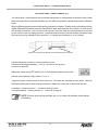
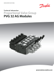
Installation Manual
& Technical Information
Automatic Laser Control
Control Box
Model CB26
Model CB24+
Software Version 4.00
ATI-010864 Rev D
Disclaimer
All documentation, data, dimensions, and drawings in this manual were compiled and checked with
great care, however Apache Technologies, Inc. cannot assume responsibility for possible errors or
omissions. We reserve the right to change designs and specifications without notice.
Apache Technologies, Inc. accepts no liability whatsoever for direct or indirect damage that may
occur due to the unauthorized or improper use or interpretation of this document, and also shall
not be held liable for direct or consequential damages resulting from improper service, application,
maintenance or use of the product.
This document is strictly for the use of qualified service technicians with the requisite technical skills,
training, and facilities. This manual should be read completely before installing the product.
Reproduction of any or all parts of this manual, including electronic, is prohibited without the written
permission of the Apache Technologies, Inc. It also may not be used for any purpose other than
for which it was intended, nor made accessible or communicated in any form to any third party not
expressly authorized by Apache Technologies, Inc.
October 2005
Apache Technologies, Inc.
8261 State Route 235
Dayton, OH 45424 USA
Phone: (937) 482-0200
Fax: (937) 482-0030
Website: www.apache-laser.com
Email: [email protected]
TABLE OF CONTENTS
T
Safety ............................................................................................... 2
Pre-Installation ................................................................................. 3
General Installation .......................................................................... 3
Control Box Controls and Displays ................................................... 7
Control Box Configuration and Set Up ............................................. 9
APPENDICES
A. CB26 or CB24+ Operator’s Manual .............................................. 15
B. Hydraulic Valve Guide and Valve Wiring ...................................... 16
C. Cable Diagrams ........................................................................... 19
D. LED Counter Switch .................................................................... 22
E. Operation Switches Reference Page ........................................... 23
F. Installation Switches Reference Page .......................................... 24
G. Advanced Installation Switches Reference Page ........................ 25
H. Internal Switches Reference Page .............................................. 26
I. Self Diagnosing Fault Codes ......................................................... 27
J. Valve Identification and Setting Recomendation ........................... 29
K. Miscellaneous Installation Information .......................................... 30
© Apache Technologies, Inc. 2005
All rights reserved. No part of this manual may be reproduced, or transmitted in any form
or by any means, electronic, mechanical, photocopying, recording, or otherwise, without
prior written permission of Apache Technologies, Inc.
Automatic Control
1
SAFETY
Meaning of Symbols
WARNING: Indicates a potential hazardous situation, which could result in death or serious injury.
CAUTION: Indicates a potentially hazardous situation, which could result in a minor or moderate
injury and/or material, financial, or environmental damage.
NOTE: Important information to enable the product to be used in a correct and efficient manner
unrelated to safety.
NOTE: The installation technician should be a qualified person who is familiar with the installation,
construction, and operation of the machine and laser equipment and the hazards involved.
NOTE: The user of this product is expected to follow all operating and safety instructions of this manual
and of the machinery operator’s manual. Perform periodic checks of the product’s performance. The
manufacturer or its representatives assume no responsibility for results of the use of this product
including any direct, indirect, consequential damage, and loss of profits. Check your work frequently.
WARNING: High pressure fluid is present in operational hydraulic systems. Fluids under high
pressure are dangerous and can cause serious injury or death. Do not make modifications, repairs
or adjustments to any hydraulic system unless you are competent or working under competent
supervision. If in doubt consult a qualified technician or engineer.
WARNING: When working near construction or agricultural machinery, follow all safety precautions
as described in the machinery’s user manual. Familiarize yourself with all basic functions of the
machine before operating or beginning any work.
WARNING: Do not remove the back panel of the control box. The back panel is to be accessed by
authorized Apache Technologies service personnel only.
WARNING: Be aware of all overhead obstructions and electrical power lines. The receiver and mast
may be higher than the machinery. Remove when transporting.
WARNING: When excavating or trenching, follow all excavation and trench safety regulations and
practices.
CAUTION: Do not disassemble any part of the receiver other than to replace batteries. The receiver
is to be serviced by authorized Apache Technologies service personnel only.
CAUTION: Ensure all equipment is properly installed, the BULLSEYE receiver is secured in its
mounting position, and all cables connections are tight and secure.
NOTE: Environmental Limits: Suitable for use in an atmosphere appropriate for human habitation (no
protection in an aggressive or explosive environment).
Automatic Control
2
PRE-INSTALLATION
The following should be reviewed with the owner and/or operator prior to installation:
• Machines must be within the manufacturer’s specification for fine grading. Loose
linkage or “slop” between the blade and lifting cylinder will adversely affect grade
performance.
• Similarly, uneven cutting edge wear will result in non-uniform grade surfaces.
• Existing wear or damage to the machine’s hydraulic system including heat damage,
oil contamination, existing leaks at fittings, hoses, valves, or cylinders and kinks or
abrasion damage to hoses should be addressed.
• Maintenance program or rebuild/overhaul history if the machine is an older model.
GENERAL INSTALLATION
System Description - CB26
Apache Automatic Blade Control is used on construction grading machinery to automatically
control the blade in earthmoving and grading applications. It is also used on agricultural drainage
and land leveling machinery.
A single BULLSEYE laser receiver mounts above the cutting edge of the blade. The Model CB26
control box mounts in the machine's cab. A hydraulic installation kit ties into the machine’s hydraulic system. Grade information from a rotating laser is processed and automatically directs
the machine’s hydraulics to maintain the elevation of the blade.
The Model CB26 control box will work with many types of hydraulic valves, from on/off (bangbang) solenoid valves to fully proportional valves.
The system is designed to work with a single BULLSEYE machine control receiver. The system
will accept BULLSEYE models 5, 5+, 5MC, or 6.
NOTE: If the BULLSEYE receiver was purchased prior to the purchase of the control
box, check with the factory as updates to the receiver may be required. Please have
the receiver model and serial number available. These updates are free of charge.
Automatic Control
3
GENERAL INSTALLATION
System Description - CB24+
The Model CB24+ control box is similar in configuration to the Model CB26 control box, but there
are some differences.
The Model CB24+ control box will work with only on/off (bang-bang) solenoid valves. It will not
work with proportional current or proportional voltage valves.
The CB24+ is designed to work with a single BULLSEYE machine control receiver. The system
will accept BULLSEYE models 3+, 5+, 5MC, or 6.
The valve drive selector switch (15) does not function with the CB24+. Refer to controls and
configuration sections beginning on page 7.
When used with the BULLSEYE 3+, the on-grade deadband is limited to 1 inch (25 mm) total.
The BULLSEYE 3+ has a total of 2 inches of proportional photocells which leaves a minimum
of 1/2 inch for grade corrections on each side. When combining wide deadbands and low gain
settings, the valve may not reach 100% valve on duty cycle on large corrections.
NOTE: The BULLSEYE 3+ is designed to work with the CB24+ control box only.
NOTE: If the BULLSEYE receiver was purchased prior to the purchase of the control
box, check with the factory as updates to the receiver may be required. Please have
the receiver model and serial number available. These updates are free of charge.
Automatic Control
4
GENERAL INSTALLATION
Components
Control Box
The Control Box should be mounted in a location that is easily visible to the operator, is within
easy reach of the operator’s hands, and can be easily installed and removed. Insure that the
location does not interfere with other machine controls or operator movements.
The Control Box has vented drain holes on the rear bottom of the unit that must face
downward.
A control box mounting bracket (ATI-950054) is designed to accept the
mounting knobs that are included with the control box.
BULLSEYE Receivers
The BULLSEYE receivers mount to round masts from sizes 1.66” to 2.00” O.D. (42 to 50 mm)
and to 1-1/2” (38 mm) square tube.
The communication protocol for the BULLSEYE receivers is proprietary RS485 @ 62.5 kbaud.
Masts
The Model STM1 shock mounted manually telescoping mast allows the receiver to be positioned
above the machinery for unobstructed laser reception. A mast mounting plate that is welded to
the blade is also available.
Installation instructions are provided with the mast and are also in Appendix J.
Hydraulic Valve:
The CB26 Control Box supports Proportional Time (PT), Proportional Current (PC), and
Proportional Voltage (PV) hydraulic valves.
The CB24+ Control Box supports Proportional Time (PT) valves only.
For specific information on these valves, please refer to Appendix B.
Hydraulic installation kits are available for several common machines. Some kits contain the
hydraulic valves, valve brackets, hydraulic hoses and fittings necessary for automatic control
of a specific machine. Other valve kits require some additional components to be supplied. A
separate installation guide is included with the hydraulic kit.
Automatic Control
5
GENERAL INSTALLATION
System Wiring
Cables are generally shipped at the predetermined length required for a particular machine.
Connectors are installed at the factory.
Plan the routing of all cables prior to actual installation.
All cables should be properly installed. Cables should be attached to the machine at a minimum
of every 2 to 3 feet (.6 to 1.0 meter) or less to try to eliminate cable movement and possible
abrasion damage. Special care should be taken at flex points to ensure the cable moves freely
and does not rub on other hoses, fittings, or the machine. Provide adequate cable length to avoid
pinching, stretching, and tight bending. Also, cables should not be clamped to pipes or hoses
that will cause the cable to be exposed to high temperatures.
Connect the 4-socket connector on the power cable to the 4-pin connector on the box. Route
the cable to the machine's battery and connect the terminal ends to the battery. The red terminal
is for the positive post and the black is for ground. The box has reverse polarity protection in
case the terminals are connected improperly.
NOTE: In order to utilize the machine's master disconnect, the ground wire must
be connected to the machine frame.
Connect the 6-pin receiver cable end to the 6-socket connector on the box. Route the cable to
the receiver. Connect the 7-socket receiver cable end to the 7-pin connector on the bottom of
the BULLSEYE receiver.
If a receiver cable with a junction block is used, follow the instructions provided with the cable.
Connect the 10-pin valve cable to the 10-socket connector on the box. Route the cable to the
valve and connect the open-ended wires to the valve following the directions for the valve.
Cable diagrams and part numbers are in Appendix C.
Optional Remote Switch
The remote switch assembly is designed to mount to lever shafts from 3/8 to 1-1/8 in.
(10 to 28 mm)
The switch can be a single function of Auto / Manual selection or can be configured with the
additional Raise / Lower function.
Cable diagrams and part numbers are in Appendix C.
Additional installation instructions are provided with the switch and are also in Appendix J.
Automatic Control
6
CONTROL BOX - CONTROLS AND DISPLAYS
Front View
3
2
4
5
1.
2.
3.
4.
5.
6.
7.
8.
9.
6
1
LED grade display
Power ON / OFF push switch
Power ON indicator
Automatic / Manual toggle switch
Automatic ON indicator
Manual ON indicator
Raise / Lower toggle switch
Access panel thumbscrews
Access panel
7
8
8
9
10
11
12 13
Operation
Switches
14
15
Operation Switches:
10. Rotary switch - On-Grade Deadband selections
(Default setting is "8".)
11. Dip Switch 4-way - Performance selections
(Default setting is all in the OFF position.)
12. Rotary switch - Valve gain (speed)
(Default setting is "8".)
16
Installation Switches:
13. Rotary switch - Valve balance (raise/lower)
(Default setting is "8".)
14. Dip Switch 4-way - Valve set-up
(Default setting is all in the OFF position.)
15. Dip Switch 4-way - Valve drive selector
(Default setting is all in the OFF position.)
Installation
Switches
16.
Fuse, 25 amp
The 3 left side switches (10, 11, 12) are used by the operator to set operating functions.
The 3 right side switches (13, 14, 15) are used during installation for specific valves and machine
settings. These should not be changed by the operator.
Automatic Control
7
CONTROL BOX - CONTROLS AND DISPLAYS
Rear View
17
18
22
22
19
20
21
17.
18.
19.
20.
21.
22.
Automatic Control
6-socket connector - laser receiver
7-socket connector - optional remote switch
10-socket connector - hydraulic valve outputs
4-pin connector - machine power input
Identification / serial number label
Mounting knobs for bracket
8
CONTROL BOX - CONFIGURATION
Valve Selection (15)
The Valve Drive Selector Dip Switch (15) is used to select the type of valve to be driven when
used with the CB26 Control Box. Following are the types of valves supported:
PT - Proportional Time
PV - Proportional Voltage
PC - Proportional Current
On/off (bang-bang) valve drive
Danfoss valve drive
Various dither frequencies (Hz) and
dither amplitudes (% of maximum correction)
Additional information on the types of supported valves are in Appendix B.
Reference Appendix J for a list of common valve models and their Control Box settings.
NOTE: The CB24+ Control Box supports PT valves only. Switch settings are not functional.
CB 26 Settings are as follows:
PT
PC
50 Hz, 10%
PC
50 Hz, 20%
PV
PC
100 Hz, 10%
PC
100 Hz, 20%
PC
200 Hz, 10%
PC
200 Hz, 20%
PC
400 Hz, 10%
PC
400 Hz, 20%
Switch Bats
in ON position
Proportional Current Valves: Dither is a signal which is constantly sent to the valve that causes
the spool to vibrate and stay lubricated. This reduces hysteresis and stiction.
Choose a setting closest to the manufacturers recommendations.
If cylinder lines or cylinder are vibrating from dither, select a higher frequency and/or
lower the % amplitude.
If the valve is sticking or sluggish, select a lower dither frequency and/or a higher
% amplitude.
If the control box power was on during valve selection, cycle the box power before proceeding.
Automatic Control
9
CONTROL BOX - CONFIGURATION
If auxiliary valve drivers and remote switches are desired, please consult the factory. Auxiliary
valve drivers can be used via remote switches to drive other functions like scraper bowl eject,
gate open and close, etc.
Once the proper valve is selected, perform a system communication check. Turn the box on to
confirm power. Check that the receiver is communicating properly. Check the raise/lower and
auto/manual switches. Check the remote switch functions if installed.
Check for proper hydraulic system operation. Ensure there are no leaks, excessive engine load
or pressure relief valves continually opening. Check that all circuits function properly.
NOTE: Before proceeding, warm up the hydraulic system to operating temperature.
Run the machine at operating RPM for approximately 15 minutes while cycling the
blade lift cylinder.
Valve Set Up (14) - Set Valve Minimum Correction
V
The Valve Minimum Correction (VMC) is set to provide output flow as soon as a correction signal
is received providing ffor optimum system performance.
The edges of the valve spool have some degree of overlap with the corresponding edges of the
valve body ports. This is required to prevent flow across the spool when it is in a neutral position.
This spool overlap means that there will be a defined movement of the spool in the bore before
flow begins to take place. This characteristic is sometimes referred to as valve “deadband”. In
this text, adjusting the control box to account for this deadband and create a minimum blade
velocity will be referred to as the Valve Minimum Correction (VMC) to avoid any confusion with
laser system deadband or accuracy.
Spool Overlap - Minimum distance
to move valve for flow to begin.
The VMC is adjusted by using the LED Counter Switch as described in Appendix D. Adjustment
is made for both the raise minimum correction and the lower minimum correction.
The VMC for PT valves is adjusted in increments of time. The VMC for PC or PV valves is a
percentage of maximum valve correction.
Valve Type
PT
PC, PV
Automatic Control
VMC Increment
10 ms
2% of max.
10
Adjustment Range
0 - 310 ms
0 - 62% of max.
CONTROL BOX - CONFIGURATION
Valve Set Up (14) - Set Valve Minimum Correction
V
Set the machines throttle to normal operating RPM.
Place the blade approximately 1 foot (0.3 m) above the ground.
No laser is required.
RAISE Minimum Correction: (switch 1 in ON position)
1. Toggle raise/lower switch to raise and hold.
2. If no blade movement, release switch. If there is movement, skip to step 5.
3. Toggle automatic/manual switch once to auto to increase VMC one unit.
4. Return to step 1.
5. Observe blade speed. Goal is 0.5 inches (13 mm) per second.
6. If blade speed is too slow, continue increasing VMC and checking blade speed.
If blade speed is too fast, toggle A/M switch towards manual to decrease VMC.
7. After proper VMC setting is obtained, note value.
8. Adjust DIP switch to OFF position.
LOWER Minimum Correction: (switch 2 in ON position)
1. Toggle raise/lower switch to lower and hold.
2. If no blade movement, release switch. If there is movement, skip to step 5.
3. Toggle automatic/manual switch once to auto to increase VMC one unit.
4. Return to step 1.
5. Observe blade speed. Goal is 0.5 inches (13 mm) per second.
6. If blade speed is too slow, continue increasing VMC and checking blade speed.
If blade speed is too fast, toggle A/M switch towards manual to decrease VMC.
7. After proper VMC setting is obtained, note value.
8. Adjust DIP switch to OFF position.
Note: It is advisable to log the various settings for each particular machine.
Automatic Control
11
CONTROL BOX - CONFIGURATION
Set Valve Raise / Lower Balance (13)
The valve raise / lower balance set-up allows adjustment to compensate for different raise /lower
blade velocities due to cylinder imbalance or for different hydraulic system responses to different
loads.
Most mobile equipment uses double-acting hydraulic cylinders. Double-acting cylinders are also
called differential cylinders because the effective area, and therefore the volume, of each end of
the cylinder is different. The rod end of the cylinder has less area and volume than the cap end
by the nature of the rod being present. This differential area and volume causes a different force
and velocity during extension and retraction - or raising and lowering for a lift cylinder.
Cap end of cylinder has greater volume and area than rod end.
Set the machines throttle to normal operating RPM.
Place the blade approximately 1 foot (0.3 m) above the ground.
No laser is required.
Adjust the valve set-up DIP switch (14) to the dynamic balance set mode.
Set the valve balance rotary switch (13) to 8.
Toggle the raise / lower switch to raise and hold. The blade will oscillate up and down. Observe
the blade drifting up or down during oscillation. Adjust the rotary pot to minimize the drift.
Clockwise - toward position F - if blade is drifting down.
Counterclockwise - toward position 0 - if blade is drifting up.
NOTE: Ensure valve set-up switches are in run mode (all switches down) before
proceeding
Automatic Control
12
CONTROL BOX - CONFIGURATION
Set Performance Options and System Gain
Refer to the operator's manual for setting performance options that include laser beam strike
averaging, receiver LED's on or off, and control box LED's bright or dim.
Generally, linear gain is selected for valves that have spools with an aggressive or exponential
flow characteristics. Exponential gain is selected for valves that have spools with less aggressive
or linear flow characteristics. Linear gain is the default position. Machine stability and hydraulic
system reaction also influence the selection.
Presetting System Gain
Blade in Air Method:
Ensure valve set up switches are in run mode.
Set the machines throttle to normal operating RPM. Ensure the machine is on flat ground.
Place the blade approximately 1 foot (0.3 m) above the ground.
Set up the rotating laser at a typical working range. If a selectable rotation speed is available, set
it to 600 RPM or faster.
Mount the receiver in its normal operating position to receive the laser.
Select an On-grade deadband (10) of approximately 1/2 of the jobsite tolerance. If working at
ranges that exceed 500 feet (150 m), this may be increased to compensate for the rotating
laser's beam "bounce".
Select manual control (4). Raise the blade to position the receiver at the lower edge of its vertical
reception range, but still receiving the beam. Select automatic control (4).
The blade and receiver will move towards on-grade. Note any overshooting of On-grade. Repeat
procedure for raise correction. Once again, note any overshooting of On-grade. Adjust the Valve
Gain switch (12) until there is one small overshoot for a full receiver length correction in either
direction.
Clockwise rotation - towards F - corresponds to a faster, but less stable correction.
Counterclockwise rotation - towards 0 - corresponds to a slower, but more stable correction.
Set the Valve Set-up switch (14) to Run Mode after completion.
A 5 second timer is also available for checking blade velocities. When set in
this mode, the raise or lower switch will activate the blade for 5 seconds when
the switch is held in the raise or lower position. The cylinder stroke can then be
measured. Ensure proper clearance when using the timer.
Automatic Control
13
CONTROL BOX - CONFIGURATION
Check System Performance
Set up the rotating laser at a typical working range. Select the RPM of the laser to 600 RPM or
faster if available.
Mount the BULLSEYE receiver to the mast of the machine in a position to receive the beam.
Select an On-grade deadband less than the jobsite tolerance. Typically 1/2 the tolerance is the
value used as a starting point.
For example, if the jobsite tolerance is ± ½", set the On-Grade Deadband rotary switch (10) to 5.
This is a deadband of ± ¼ inch or 0.50 inch total deadband.
Ensure other switches are set to "Run Mode" and the other desired options.
Fine tune the Valve Gain (12) while working in typical material and operating conditions.
If the system is over correcting or too jumpy, decrease the gain setting.
If the system is not correcting fast enough or is sluggish, increase the gain setting.
Environmental factors and laser set up can also affect system performance. Follow the set up
procedures for your laser. Ensure proper tripods are used for stable laser operation.
Changing the laser RPM, laser strike averaging, deadband, gain type, gain setting, valve
balance, or valve minimum corrections can affect system performance. System operation should
be rechecked after changing any of these parameters.
Automatic Control
14
APPENDIX A
Control Box Operator’s Manual
An operator’s manual is included as part of this installation manual.
If missing, please request an additional copy.
CB26 Control Box Operator’s Manual
CB24+ Control Box Operator’s Manual
Automatic Control
15
Part No. ATI-026012 Rev E
Part No. ATI-026023 Rev C
APPENDIX B
Hydraulic Valve Guide
PT - Proportional Time Valve:
The PT valve, sometimes referred to as on/off or "bang-bang" valve is not a true proportional
valve. It can only be turned on or off.
The proportionality
tionality is achieved by rapidly turning the valve on and off over time at varying duty
rates as shown in the chart below.
Gain = 1
Gain = 8
Lower
Correction
Gain = F
On Grade
Deadband
Gain = F
Raise
Correction
Gain = 8
Gain = 1
0%
Valve Min.
Correction
50%
100%
PT Valve Signal
(% On, Duty Cycle)
Full machine voltage is applied to the valve to turn it on.
To achieve desired flow rates at "100% on" corrections, proper sizing of the valve or a flow
control device is required.
Application Note: These valves as a group are least expensive, but control performance is not
as smooth as with the PC or PV valves.
Since this type of valve pops open or closed over time, the hoses can jump about and the
rushing hydraulic fluid actually make a snapping sound, hence the name "bang bang" valve is
often used.
PT Valve Wiring: (P/N ATI-026040-XX)
Orange
White
Black
White/Black
1
2*
Lower
Raise
Switched Power
Load Sense
Raise
Coil
Not Used
Lower
Coil
GND
Ground
Ground
1
2*
3 or 4
Danfoss PT Amp Connector
Red
CB26 or CB24+
10-Socket
Connector
A
B
C
D
E
F
G
H
I
J
Danfoss PT Hirschmann Connector
Blue
Green
*Raise cylinder port is the port closest to black electronics module.
Automatic Control
16
APPENDIX B
Hydraulic Valve Guide
PC - Proportional Current Valve:
PC valves are proportional spool valves.
Gain = 1 (Linear)
Gain = 8 (Linear)
Lower
Correction
Gain = 8 (Exponential)
Gain = F (Linear)
On Grade
Deadband
Gain = F (Linear)
Raise
Correction
Gain = 8 (Exponential)
Gain = 8 (Linear)
Gain = 1 (Linear)
0%
Valve Min.
Correction
50%
100%
PC Valve Signal
(% of Maximum Current)
The maximum current supplied to the valve solenoid is equal to machine voltage divided by
coil resistance.
Pulse Width Modulation (PWM) is used to create the < 100% proportional current signal.
The PC signal energizes 1 coil at a time which slides the valve's spool back and forth changing
the valve's orifice size which changes the oil flow rate.
If the valve's maximum current rating is less than the maximum supplied current, (machine
voltage / coil resistance), use the PC valve current set mode (Appendix G) to lower the maximum
supplied current to within the valve's maximum rated current. Reference Appendix J for PC
valve identification and control box settings.
Application Note: PC Valves are typically fast, but not always accurate.
Direct operated solenoid PC Valves are limited in flow rates to about 8 GPM (30 l/m) due to the
force capability of 12V solenoids.
PC Valve Wiring: (P/N ATI-026040-XX)
Blue
Green
Red
CB26 or CB24+
10-Socket
Connector
Orange
White
Black
White/Black
Automatic Control
A
B
C
D
E
F
G
H
I
J
Lower
Raise
Switched Power
Load Sense
Raise
Coil
Not Used
Ground
Ground
17
Lower
Coil
APPENDIX B
Hydraulic Valve Guide
PV - Proportional Voltage Valve:
Namely, Danfoss PVG32, pilot operated proportional valves with "on-board" electronics, spool
position and fault monitoring.
Gain = 1 (Linear)
Gain = 8 (Linear)
Lower
Correction
Gain = 8 (Exponential)
Gain = F (Linear)
On Grade
Deadband
Raise
Correction
25%
0%
50%
Valve Min.
Lower
Correction
75%
100%
Valve Min.
Raise
Correction
PV Valve Signal
(% of Machine Voltage)
The PV valve signal is a low power ratiometric voltage signal that references the switched
power output (machine voltage).
I.e.
50% of machine voltage = No flow
25% of machine voltage = Full lower
75% of machine voltage = Full raise
Danfoss diagnostics:
Green LED on valve = OK
Red LED on valve = Fault
Application Notes: PV valves provide larger flows up to 32 GPM (120 l/m) and have more
accurate flows. For best performance use PVEH actuation modules and linear spools.
Valves are easily converted to interface with open center, closed center, and load sensing
hydraulic systems.
Raise cylinder port is the port closest to the black electronics module.
PV Valve Wiring: (ATI-026040-XX)
CB26
10-Socket
Connector
Orange
White
Black
White/Black
Automatic Control
Not Used
3
1
D.F. Diagnostic
Switched Power
Load Sense
2
PV Signal
GND
Ground
Ground
18
4
2
1
3
Danfoss Amp. Connector
Red
A
B
C
D
E
F
G
H
I
J
Danfoss Hirschmann Connector
Blue
Green
APPENDIX C
Cable Diagrams
7 SOC
7 PIN
Automatic/Manual
Raise/Lower
Remote Switch
Automatic/Manual
Remote Switch
3
6 PIN
BULLSEYE
3+, 5+, 5MC, 6
(Note: 3+ works with
CB24+ only)
6 SOC
6
1
or
or
7
2
6 PIN
6 SOC
7 SOC
4 PIN
10 SOC
Control Box
CB 26 or CB24+
4 SOC
7 PIN
10 PIN
5
4
Master
Disconnect
Switch
+
—
10 --30V
30 VDC
10
DC
PV Valve
PC or PT Valve
Number
Part Number
Description
1
ATI 024013-xx
Receiver cable
2
ATI 024019-xx
Receiver cable with mounting block for coil cord
3
ATI 024104
4
ATI 024012-xx
Coil cord
Power cable
5
ATI 026040-xx
Valve cable for PT / PC / PV valves
6
ATI 026017-xx
Remote switch cable - auto/manual
7
ATI 026016-xx
Remote switch cable - auto/manual and raise/lower
-xx reprsents cable length in feet.
Note: The CB24+ Control Box works with PT valves only.
Automatic Control
19
APPENDIX C
Cable Diagrams
Receiver Cable ATI-0240013-xx (-xx represents cable length in feet)
Red - Power
A
Green - Comm.
B
White - Comm.
C
Black - Ground
D
Not Used
E
Not Used
F
Not Used
G
A
F
B G E
D
C
F
A
E
D
B
C
A
Red - Power
B
Green - Comm.
C
White - Comm.
D
Black - Ground
E
Not Used
F
Not Used
A
Red - Power
B
Green - Comm.
C
White - Comm.
D
Black - Ground
E
Not Used
F
Not Used
A
Red - Power
B
Green - Comm.
C
White - Comm.
D
Black - Ground
E
Not Used
F
Not Used
A
Black - Ground
B
White - Ground
C
Red - Power
D
Green - Power
Receiver Cable with Mounting Block ATI-024019-xx
Red - Power
A
B
Green - Comm.
B
C
White - Comm.
C
Black - Ground
D
Not Used
E
Not Used
F
A
F
D
E
F
E
A
D
B
C
Coil Cable ATI-024104
Red - Power
A
Green - Comm.
B
White - Comm.
C
Black - Ground
D
Not Used
E
F
Not Used
F
E
Not Used
G
A
F
B G E
C
D
A
D
B
C
Power Cable ATI-024012-xx
Automatic Control
20
A
D
B
C
APPENDIX C
Cable Diagrams
Valve Cable ATI-026040-xx (-xx represents cable length in feet)
A
Blue - PT/PC Lower
B
Green - PT/PC Raise, PV Fault
C
Red - Switched Power
D
Orange - Load Sense
E
White - PV Signal
F
G
A
H
G
I
B
F
J
C
E
D
H
I
Black - Ground
J
White/Black - Ground
Remote Switch Cable
ATI-026016 (Auto/manual and raise/lower)
ATI-026017 (Auto/manual only)
F
A
E G B
D
C
Orange
A
Auto / Manual
Green
B
Raise / Lower
Not Used
C
Aux Remote 0
Not Used
D
Aux Remote 1
Not Used
E
Red
F
Power
Black
G
Ground
Raise / Lower
Switch
Auto / Manual
Switch
Auto / Manual
Connecting Pin A to Ground toggles control to Manual.
Connecting Pin A to Power toggles to Automatic.
Raise / Lower
Connecting Pin B to Power creates a valve Raise signal (100%)
Connecting Pin B to Ground creates a valve Lower signal (100%)
Automatic Control
21
APPENDIX D
LED Counter Switch
The control box uses a combination of switches and LED's to provide a counter for various
set up operations. The Valve Minimum Correction uses this counter for adjustment of spool
overlap correction during initial set up.
When the appropriate DIP switches are selected, the LED array and Auto / Manual switch on the
front of the control box function together to form a binary counter.
Each row of LED’s represent a specific number as follows:
16
8
4
2
1
An active LED row represents that specific number. Examples:
represents 2
represents 16
Multiple rows of LED’s can be active. If multiple rows are active, the number that each row
represents are added together. Examples
represents 11
(1 + 2 + 8)
represents 18
(2 + 16)
The combinations can represent numbers from 0 to 31.
The auto / manual switch is used to change the value of the LED Counter. The auto
switch (up) increases the value. The manual switch (down) decreases the value.
Automatic Control
22
APPENDIX E
Operation Switches Reference Page
On-Grade Deadband
(10)
Pot
Deadband
Value
in.
mm
0
0.0
0.0
1
0.1
2.5
2
0.2
5.1
3
0.3
7.6
4
0.4
10.2
5
0.5
12.7
6
0.6
15.2
7
0.7
17.8
8
0.8
20.3
9
0.9
22.9
A
1.0
25.4
B
1.1
27.9
C
1.2
30.5
D
1.3
33.0
E
1.4
35.6
F
1.5
38.1
Performance Options
(11)
1
2 Strike
Averaging OFF
2 Strike
Averaging ON
2
Receiver LED
Disable OFF
Receiver LED
Disable ON
3
Control Box
LED’s Bright
Control Box
LED’s Dim
4
Exponential Gain
Factory Default Setting = 8
Valve Gain
(12)
Distance from Deadband
to Full Blade Speed
Pot
Linear
Exponential
Value
mm
mm
0 (slow)
200
78
1
170
71
2
148
63
3
129
57
4
112
53
5
98
47
6
86
42
7
75
37
8
65
33
9
56
28
A
48
25
B
40
21
C
33
17
D
26
14
E
19
11
F (fast)
12
8
Linear Gain
Factory Default Setting = 8
Factory Default Setting = All OFF
Automatic Control
23
APPENDIX F
Installation Switches Reference Page
Valve Balance
(13)
Pot
Valve Set-up
(14)
Run Mode
Value
0
Lower =
8.00 x Raise
1
Lower =
7.07 x Raise
2
Lower =
6.13 x Raise
3
Lower =
5.20 x Raise
4
Lower =
4.27 x Raise
5
Lower =
3.33 x Raise
6
Lower =
2.40 x Raise
7
Lower =
1.47 x Raise
8
Raise =
1.47 x Lower
9
Raise =
2.40 x Lower
A
Raise =
3.33 x Lower
B
Raise =
4.27 x Lower
C
Raise =
5.20 x Lower
D
Raise =
6.13 x Lower
E
Raise =
7.07 x Lower
F
Raise =
8.00 x Lower
Factory Default Setting = 8
Automatic Control
Raise Valve Minimum
Correction Mode
Drives valve at VMC
value with R switch
Factory Setting = 0
Lower Valve Minimum
Correction Mode
Drives valve at VMC
value with L switch
Factory Setting = 0
Dynamic Balance
Set Mode
Use with Valve Balance
Switch (13)
Oscillates blade with
raise or lower switch
5 Sec. Timer
If sustained R or L, will
time out after 5 sec.
Valve Drive Selection
(15)
(CB 26 Only)
PT
PV
Factory Default
Setting
PC
50 Hz, 10%
PC
100 Hz, 10%
PC
200 Hz, 10%
PC
400 Hz, 10%
PC
50 Hz, 20%
PC
100 Hz, 20%
PC
200 Hz, 20%
PC
400 Hz, 20%
Factory Default Setting = All OFF
24
APPENDIX G
Advanced Installation Switches Reference Page
Valve Set-up (14)
NOTE: The advanced installation switches are used for special applications and
circumstances. In general, default settings for the functions below will suffice for
most applications.
Value for the following functions are adjusted with the LED counter switch as
described in Appendix D.
Load Sense Set Mode
0 = Load Sense OFF
1 = Load Sense ON
Factory setting = 0
(Software version 4.0 and later)
Switched Power Mode for PT / PC Valves. (Switched power is always on for PV valves.)
0 = Switched power OFF
1 = Switched power ON
Factory setting = 0
(Software version 4.0 and later)
Display Averaging Set Mode - Uses strike averaging to smooth LED display.
Takes into account laser RPM.
0 = Adaptive
1 = 1 strike
2 = 9 strike weighted average
3 = 13 strike weighted average
Factory setting = 0
Maximum Valve Current Set Mode
Limits pulse width modulation (PWM) which limits current sent to PC & PT valves at maximum
correction.
0 = 100% maximum PWM = full current
1 – 25 = 96% – 0% of full current
Factory setting = 0
PC Valves: Included with S/N 0201 and higher (Software Version 3.0 and later).
PT Valves: Included with Software Version 4.0 and later
Control Deadband Set Mode - Determines if the corrections drive to the edges or inside the deadband.
0 = Corrections per on-grade deadband switch (10) setting.
1 = Inward corrections stop @1/2 on-grade deadband setting, outward corrections start @ on-grade
deadband setting.
2 = Inward corrections start and outward corrections stop @ 1/2 on-grade deadband setting.
Factory setting = 0
Automatic Control
25
APPENDIX H
Internal Switches Reference Page
The main circuit board inside the control box has two additional 4-way dip switches.
Switch 101 functions are described below.
Switch 100 is used for auxiliary valve configurations and other test simulations.
SW100
SW101
(Factory Settings)
(Factory Settings)
1
Manual Raise/Lower
Override in Auto OFF
Manual Raise/Lower
Override in Auto ON
2
False Strike
Rejection Disabled
False Strike
Rejection Enabled
3
Manual R/L Ramp OFF
Manual R/L Ramp ON
Default ON position allows the manual raise
switch to send the raise signal to the valve
even when in the automatic mode.
Default ON position filters out signals that are
out of time with laser, strike multiple channels
at the same time (strobes), or are at an unrealistic vertical distance from the previous strike.
Default ON position allows a progressive
increase for the valve to get to the 100% open
state in the first second.
4
Test Mode
Operating Mode
Automatic Control
26
APPENDIX I
Self Diagnosing Fault Codes
When the Control Box recognizes a fault, all receiver LED's will light solid and the Power, Auto
and Manual LED’s on the control box will alternately blink.
A specific fault information number will be displayed on the LED counter as described in
Appendix D.
1. Switched Power Driver
Description: Over current (>5A)
Location: Connector – 10 socket Pin – C
Notes: Driver will shut off for 250ms. It will then retry. If 3 failed tries in 2 seconds, driver stays off until power
is cycled.
Possible External Causes: Short in cable coil or connectors.
2. Load Sense Driver
Description: Over current (>5A)
Location: Connector – 10 socket Pin – D
Notes: Driver will shut off for 250ms. It will then retry. If 3 failed tries in 2 seconds, driver stays off until power
is cycled.
Possible External Causes: Short in cable coil or connectors.
3. Auxiliary Driver 2
Description: Over current (>5A)
Location: Connector – 10 socket Pin – F
Notes: Driver will shut off for 250ms. It will then retry. If 3 failed tries in 2 seconds, driver stays off until power
is cycled.
Possible External Causes: Short in cable coil or connectors.
4. Auxiliary Driver 3
Description: Over current (>5A)
Location: Connector – 10 socket Pin – G
Notes: Driver will shut off for 250ms. It will then retry. If 3 failed tries in 2 seconds, driver stays off until power
is cycled.
Possible External Causes: Short in cable coil or connectors.
5. Raise Proportional Current (PC) & Proportional Time (PT) Driver
Description: Over current (>5A)
Location: Connector – 10 socket Pin – B
Notes: Driver will shut off for 250ms. It will then retry. If 3 failed tries in 2 seconds, driver stays off until power
is cycled.
Possible External Causes: Short in cable coil or connectors.
6. Lower Proportional Current (PC) & Proportional Time (PT) Driver
Description: Over current (>5A)
Location: Connector – 10 socket Pin – A
Notes: Driver will shut off for 250ms. It will then retry. If 3 failed tries in 2 seconds, driver stays off until power
is cycled.
Possible External Causes: Short in cable coil or connectors.
Automatic Control
27
APPENDIX I
Self Diagnosing Fault Codes
7. Proportional Voltage Diagnostics
Description: Danfoss Passive or Active fault monitoring
Location: Connector – 10 socket Pin – B
Notes: Passive Danfoss - Fault will clear when fault removed.
Active Danfoss - Fault will clear when fault removed and power cycled.
Possible External Causes: PV signal exceeds 15% - 85% of supply, LVDT wires broken or shorted,
Spool position exceeds command.
9. Proportional Voltage Driver
Description: Over current (>0.06 A)
Location: Connector – 10 socket Pin – E
Notes: Driver shuts off during fault. Fault will clear when fault removed
Possible External Causes: Short in coil cables or connectors.
15. Remote Switch Driver
Description: Over current
Location: Connector – 7 socket
Pin – F
Notes: Fault will clear when fault removed
Possible External Causes: Short in cables or connectors.
16. Receiver Communication
Description: Loss of communication
Location: Connector – 6 socket
Pin – A,B,C,D
Notes: Fault will clear when receiver communicates with the control box
Possible External Causes: Loss of power to receiver, loss of communication with receiver.
18. Machine Low Voltage
Description: Machine Power < 9.5V
Location: Connector – 4 pin
Pin – A,B,C,D
Notes: Fault will clear when voltage returns to operating range.
Possible External Causes: Low battery, voltage regulator, poor connections, undersized / over length
conductors.
19. Machine High Voltage
Description: Machine Power > 31.5V
Location: Connector – 4 pin
Pin – A,B,C,D
Notes: Fault will clear when voltage returns to operating range. If sustained, fuse will blow.
Possible External Causes: Voltage regulator, alternator, power spikes.
20. Internal Problems
Description: Control Box Proc/Ram Check
Location: Connector – N/A
Pin – N/A
Notes: Cycle control box power to clear fault. If fault doesn’t clear, control box needs serviced.
Possible External Causes: Processor or RAM problems.
Automatic Control
28
APPENDIX J
Valve Identification and Setting Recomendation
Valve Identification
Mfgr.
Model Number
Solenoid
CB26 Setting
Recommendations
Solenoid Description
ID
Drive
Dither
Dither
Current
Type
Freq.
Ampl.
Limit
(Hz.)
(%)
(LCS)
Danfoss
PVG32 with PVEH elect. Module
157B4016
12VDC, Active Fault, Hrshmn conn.
PV
N/A
N/A
N/A
Danfoss
PVG32 with PVEH elect. Module
157B4028
24VDC, Active Fault, Hrshmn conn
PV
N/A
N/A
N/A
Danfoss
PVG32 with PVEH elect. Module
157B4086
12VDC, Passive Fault, Hrshmn conn.
PV
N/A
N/A
N/A
Danfoss
PVG32 with PVEH elect. Module
157B4088
24VDC, Passive Fault, Hrshmn conn.
PV
N/A
N/A
N/A
Danfoss
PVG32 with PVEH elect. Module
157B4032
11-32VDC, Active Fault, Hrshmn conn.
PV
N/A
N/A
N/A
Danfoss
PVG32 with PVEH elect. Module
157B4033
11-32VDC, Passive fault, Hrshmn conn.
PV
N/A
N/A
N/A
Danfoss
PVG32 with PVEH elect. Module
157B4034
11-32VDC, passive Fault, Amp conn.
PV
N/A
N/A
N/A
Danfoss
PVG32 with PVEH elect. Module
157B4035
11-32VDC, Active Fault, Amp conn.
PV
N/A
N/A
N/A
Vickers/Eaton
KDG4-3S…..
GP
12VDC, 4.9 Ohms
PC
100
20%
0
Vickers/Eaton
KDG4-3S…..
HA
24VDC, 19.6 Ohms
PC
100
20%
0
Vickers/Eaton
KDG4-3S…..
G
12VDC, 1.8 Ohms
PC
100
20%
12
Vickers/Eaton
KDG4-3S…..
H
24VDC, 7.3 Ohms
PC
100
20%
12
Nachi
ESD……
24VDC, 20 Ohms
PC
100
20%
0
Parker
D1FW….
K
12VDC, 6 Ohms
PC
100
20%
0
Parker
D1FW….
J
24VDC, 24 Ohms
PC
100
20%
0
Parker
D3FW….
K
12VDC, 4 Ohms
PC
100
20%
0
Rexroth
4 WRAB6…..
G12
12VDC, 4.8 Ohms
PC
200
20%
0
Rexroth
4 WRAB6…..
G24
24VDC, 19.2 Ohms
PC
200
20%
0
Bosch
0811-404 ….
12VDC, 3.0 Ohms
PC
200
20%
9
Bosch
0811-404 ….
24VDC, 3.0 Ohms
PC
200
20%
17
Danfoss
PVG32 with PVEO elect. module
157B4216
12VDC, Hrshmn conn.
PT
N/A
N/A
N/A
Danfoss
PVG32 with PVEO elect. module
157B4228
24VDC, Hrshmn conn.
PT
N/A
N/A
N/A
Danfoss
PVG32 with PVEO elect. module
157B4901
12VDC, Amp conn.
PT
N/A
N/A
N/A
Danfoss
PVG32 with PVEO elect. module
157B4902
24VDC, Amp conn.
PT
N/A
N/A
N/A
Vickers/Eaton
DG4V-3…..
GH
12VDC, 3.8 Ohms
PT
N/A
N/A
N/A
Vickers/Eaton
DG4V-3…..
HH
24VDC, 15.9 Ohms
PT
N/A
N/A
N/A
Nachi
SS-G0…..
D1
12VDC, 4.8 Ohms
PT
N/A
N/A
N/A
Nachi
SS-G0…..
D2
24VDC, 19.2 Ohms
PT
N/A
N/A
N/A
Parker
D3W….
K
12VDC, 4 Ohms
PT
N/A
N/A
N/A
Parker
D3W….
J
24VDC, 16 Ohms
PT
N/A
N/A
N/A
Parker
BV06…..
D012
12VDC, 5 Ohms
PT
N/A
N/A
N/A
Parker
BV06…..
D024
24VDC, 20Ohms
PT
N/A
N/A
N/A
Parker
D1VW…..
K 30 watt
12VDC, 4.3 Ohms
PT
N/A
N/A
N/A
Parker
D1VW…..
J 30 watt
24VDC, 17.3 Ohms
PT
N/A
N/A
N/A
Bosch/Rexroth
4WE6….., 4WE10….
G24
24VDC, 19.2 Ohms
PT
N/A
N/A
N/A
Bosch/Rexroth
4WE6….., 4WE10….
G12
12VDC, 4.8 Ohms
PT
N/A
N/A
N/A
Continental
VSD03M…..
42L, 70L
24VDC, 24 Ohms
PT
N/A
N/A
N/A
Continental
VSD03M…..
44L, 75L
12VDC, 6 Ohms
PT
N/A
N/A
N/A
Automatic Control
29
APPENDIX K
Miscellaneous Installation Information
Remote Switch Installation Notes:
1.
The Remote Switch Assembly is designed to mount to lever shafts from 3/8" to 1-1/8"
in diameter by using the different screws provided.
2.
Determine Remote Switch mounting location for easy access during operation.
Cable should route downward from switch housing.
3.
If mounted to a moving lever, ensure there is enough cable to permit full lever travel.
4.
Remove any dirt or oils from the area where the switch will mount with isopropyl
alcohol or detergent cleaner.
5
Remove the adhesive liners on the double sticky tape and apply the switch.
6
Select the correct length of screw for the shaft diameter and tighten clamping
screws. Do not overtighten as this can distort housing and clamp.
7
Strain relief the cable by tie wrapping it to the lever as shown.
8.
Check the function with the control box.
Switch Orientation View
Receiver Cable with Mounting Block Installation Notes:
Mounting Options For ATI-024019-XX
Grill Mounting
JD 450-650H Dozers
1
2.
Automatic Control
Notch top fin for strain relief
clearance & mount to grill.
Leave service loop for
opening grill.
Grill Mounting
CAT D3-D5G Dozers
- Loosen top radiator mounts
to provide clearance for cable
connector routing past radiator.
30
Hood Mounting
- If no access for cable around
radiator, lay block on its side &
mount to top of hood.
APPENDIX K
Miscellaneous Installation Information
STM1 Telescoping Manual Mast Installation Notes:
1. Observe all safety practices recommenced by the machinery
manufacturer while installing and using the mast.
a) Turn off engine and engage parking brake.
b) Rest blade on the ground.
c) Take precautions to avoid lifting or falling injuries. Mast weight is
57 Lbs. (26 kg.)
To minimize elevation errors due to changing cut depths:
a) The mast should be positioned to place the laser receiver
as close as possible vertically over the cutting edge of the
blade.
b) The mast should be vertical "front-to-back" when the blade is in
its normal operating position.
2
To minimize elevation errors due to changing blade tilt on
single laser receiver systems:
a) The mast should be mounted near the center of the
blade.
b) The mast should be vertical "side-to-side" when the blade is in its
normal operating position.
3
Weld the optional mast mounting plate (ATI-010766) to
best meet the above recommendations, and:
a) Not interfere with blade movement or linkages.
b) Provide clearance for pin removal, or other service
requirements.
c) Follow all machine manufacturer precautions for welding to the
machine.
d) Several pieces of material are usually required to stand the plate
slightly above a dozer blade. These pieces are not included with
the mounting plate.
4
5
6
7
Attach the mast to the mounting plate with provided (1) 3/410 x 2-1/2 inch long grade 8 screw and lockwasher. Torque
to 265 ft-lbs. (37 mkg)
Attach the laser receiver to the mast as shown. Wrap the
electrical cable around the mast to keep it out of harm from
blade linkages or material near the blade. Attach the cable
to the laser receiver.
Loosen the mast clamp and extend the mast to the desired
elevation to clear obstructions such as the machines cab.
Tighten the mast clamp.
a) Pull out on the clamp handle to reposition the handle.
Automatic Control
31