1
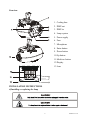
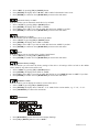
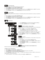
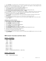
 PROFESSIONAL LIGHT USER’S MANUAL
MC-3
KEEP THIS MANUAL FOR FUTURE NEEDS
For your own safety, please read this user manual carefully before installing the device.
Every person involved with the installation, operation and maintenance of this device has to
- be qualified
- consider this manual to be part of the total product
- keep this manual for the entire service life of the product
- pass this manual on to every further owner or user of the product
- download the latest version of the user manual from the Internet
INTRODUCTION:
Thank you for having chosen this professional lighting. You will see you have acquired a powerful
and versatile device.
Unpack the device. Inside the box you should find:
1: The fixture device
2: A power cable
3: An XLR connection cable
4: A safety cable and this manual.
Please check carefully that there is no damage caused by transportation. Should there be any, consult
your dealer and don’t install this device.
SAFETY INSTRUCTIONS
This device has left our premises in absolutely perfect condition. In order to maintain this condition
and to ensure a safe operation, it is absolutely necessary for the user to follow the safety instructions
and warning notes written in this user manual.
Important:
Damages caused by the disregard of this user manual are not subject to warranty. The dealer
will not accept liability for any resulting defects or problems.
If the device has been exposed to drastic temperature fluctuation (e.g. after transportation), do
2
XM037-V1.3-A
not switch it on immediately. The arising condensation water might damage your device. Leave
the device switched off until it has reached room temperature.
Please make sure that there are no obvious transport damages. If you notice any damages on the
A/C connection cable or on the casing do not take the device into operation and immediately
consult your local dealer.
This device falls under protection-class I. The power plug must only be plugged into a protection
class I outlet. The voltage and frequency must exactly be the same as stated on the device.
Wrong voltages or power outlets can lead to the destruction of the device and to mortal electrical
shock.
Always plug in the power plug last. The power plug must always be inserted without force.
Make sure that the plug is tightly connected with the outlet.
Never let the power-cord come into contact with other cables! Handle the power-cord and all
connections with the mains with particular caution! Never touch them with wet hands, as this
could lead to mortal electrical shock.
Never modify, bend, strain mechanically, put pressure on, pull or heat up the power cord. Never
operate next to sources of heat or cold. Disregard can lead to power cord damages, fire or mortal
electrical shock.
The cable insert or the female part in the device must never be strained. There must always be
sufficient cable to the device. Otherwise, the cable may be damaged which may lead to mortal
damage.
Make sure that the power-cord is never crimped or damaged by sharp edges. Check the device
and the power-cord from time to time.
If extension cords are used make sure that the core diameter is sufficient for the required power
consumption of the device. All warnings concerning the power cords are also valid for possible
extension cords.
Always disconnect from the mains, when the device is not in use or before cleaning it. Only
handle the power-cord by the plug. Never pull out the plug by tugging the power-cord.
Otherwise, the cable or plug can be damaged leading to mortal electrical shock. If the power
plug or the power switch is not accessible, the device must be disconnected via the mains.
If the power plug or the device is dusty, the device must be taken out of operation, disconnected
and then be cleaned with a dry cloth. Dust can reduce the insulation that may lead to mortal
electrical shock. More severe dirt in and at the device should only be removed by a specialist.
There must never enter any liquid into power outlets, extension cords or any holes in the housing
of the device. If you suppose that also a minimal amount of liquid may have entered the device,
it must immediately be disconnected. This is also valid, if the device was exposed to high
humidity. Also if the device is still running, the device must be checked by a specialist if the
liquid has reduced any insulation. Reduced insulation can cause mortal electrical shock.
There must never be any objects entering into the device. This is especially valid for metal parts.
If any metal parts like staples or coarse metal chips enter into the device, the device must be
taken out of operation and disconnected immediately. Malfunction or short-circuits caused by
metal parts may cause mortal injuries.
During the initial start-up some smoke or smell may arise. This is a normal process and does not
necessarily mean that the device is defective.
Caution: During the operation, the housing becomes very hot.
Do not switch the device on and off in short intervals as this would reduce the lamp’s life.
3
XM037-V1.3-A
Keep away children and amateurs!
Never leave this device running unattended.
OPERATING DETERMINATIONS
This device is a light spot for creating decorative effects. This product is designed for indoor use
only.
This device is designed for professional use, e.g. on stages, in discotheques, theatres etc.
Lighting effects are not designed for permanent operation. Consistent operation breaks will
ensure that the device will serve you for a long time without defects.
Do not shake the device. Avoid brute force when installing or operating the device.
Never lift the fixture by holding it at the projector-head, as the mechanics may be damaged.
Always hold the fixture at the transport handles.
When choosing the installation-spot, please make sure that the device is not exposed to extreme
heat, moisture or dust. There should not be any cables lying around. You endanger your own and
the safety of others!
This device must never be operated or stockpiled in surroundings where splash water, rain,
moisture or fog may harm the device. Moisture or very high humidity can reduce the insulation
and lead to mortal electrical shocks. When using smoke machines, make sure that the device is
never exposed to the direct smoke jet and is installed in a distance of 0.5 meters between smoke
machine and device. The room must only be saturated with an amount of smoke that the
visibility will always be more than 10 meters.
The ambient temperature must always be between -5° C and +45° C. Keep away from direct
insulation (particularly in cars) and heaters.
The relative humidity must not exceed 50 % with an ambient temperature of 45° C.
This device must only be operated in an altitude between -20 and 2000 m over NN.
Never use the device during thunderstorms. Over voltage could destroy the device. Always
disconnect the device during thunderstorms.
The symbol
determines the minimum distance from lighted objects. The minimum
distance between light-output and the illuminated surface must be more than this value.
The device must only be installed on a non-flammable surface. In order to safeguard sufficient
ventilation, you should leave 50 cm of free space around the device. Please note that
heat-sensitive objects may be deformed or damaged by the emitted heat.
Make sure that the area below the installation place is blocked when rigging, unrigging or
servicing the fixture.
For overhead use (mounting height >100 cm), always fix the fixture with an appropriate
safety-rope. Fix the safety-rope at the correct fixation points only. The safety-rope must never be
fixed at the transport handles!
Only operate the fixture after having checked that the housing is firmly closed and all screws are
tightly fastened.
The lamp must never be ignited if the objective lens or any housing-cover is open, as discharge
lamps may explode and emit a high ultraviolet radiation, which may cause burns.
4
XM037-V1.3-A
The maximum ambient temperature t = 45° C must never be exceeded.
Operate the device only after having familiarized with its functions. Do not permit operation by
persons not qualified for operating the device. Most damages are the result of unprofessional
operation!
Qualified for operating the device. Most damages are the result of unprofessional operation!
Please consider that unauthorized modifications on the device are forbidden due to safety
reasons!
Never remove the serial barcode from the device as this would make the guarantee void.
If this device will be operated in any way different to the one described in this manual, the
product may suffer damages and the guarantee becomes void. Furthermore, any other operation
may lead to dangers like short-circuit, burns, electric shock, lamp explosion, crash etc.
DESCRIPTION OF THE DEVICE
Features
·Lamp: Philips MSD 250/2
·Control signal: Standard DMX-512, 3 channels
·Stand alone operation with master/slave function, can be sound activated
·One color wheel with 8 dichroic filters plus white, with variable speed of rainbow effect
·Strobe/shutter: Strobe effect of 1-10 flash per second
·Local and remote reset
·4 digits display
·Preset program: 8 built in programs can be called up via DMX controller
·Editable program: Edit and save the program to inside EEPROM via the control board or external
controller, up to 48 scenes can be saved and then can be run in Stand alone or sound activated.
·Number of scenes in Program Run can be changed individually
·Optical:standard19°beam angle (26°optional lens)
5
XM037-V1.3-A
Overview
1. Cooling fans
2. DMX out
3. DMX in
4. Lamp system
5. Power supply
6. Fuse
7. Microphone
8. Enter-button
9. Down-button
10. Up-button
11. Mode/esc-button
12. Display
13. Lens
INSTALLATION INSTRUCTIONS
A)Installing or replacing the lamp
6
XM037-V1.3-A
Before replacing the lamp let the lamp cool down, because during operation, the lamp can reach
very high temperature.
During the installation of halogen lamps do not touch the glass bulbs bare handed. Always use a
cloth to handle the lamps during insertion and removal.
Do not install lamps with a higher wattage. They generate higher temperatures than which the
device was designed for.
For the installation, you need one PHILIPS MSD250/2
Procedure:
Lamp Replacement: Never change the lamp while be fixture is plugged in.
1) Unscrew the 2 screws (A, B) on the bottom of the housing, holding the plate where the lamp is
underneath. Carefully remove the metal plate.
2) Carefully insert the lamp into the socket. Please remember there is only one way to insert the
lamp. Gently slide the lamp and its lamp holder back into place.
3) On the access plate there are 3 screws marked 1, 2 and 3.which are used to adjust the lamp holder
in the lamp housing. You can adjust the 3 screws to fine-turn the position of the lamp to get the
maximum light output as shown below.
Fuse Replacement: Locate and remove the unit’s power cord. Once the cord has been removed
located the fuse holder located inside the power socket. Insert a flat-head screw driver into the power
socket and gently pry out the fuse holder. Remove the bad fuse and replace with a new one. The fuse
holder has a built-in socket for a spare fuse be sure not to confuse the space with active fuse.
B) Mounting the device
7
XM037-V1.3-A
The installation of the effect has to be built and constructed in a way that it can hold 10 times the
weight for 1 hour without any harming deformation.
The installation must always be secured with a secondary safety attachment, e.g. an appropriate
safety cable.
Never stand directly below the device when mounting, removing or servicing the fixture.
The operator has to make sure the safety relating and machine technical installations are
approved with an expert before taking the device into operation for the first time.
These installations have to be approved by a skilled person once a year.
Cautions:
The effect should be installed outside areas where persons may reach it, walk by or be seated.
Overhead mounting requires extensive experience, including amongst others calculating working
load limits, installation material being used, and periodic safety inspection of all installation material
and the device. If you lack these qualifications, do not attempt the installation yourself. Improper
installation can result in bodily injury.
Before mounting make sure that the installation area can hold a minimum point load of 10 times
the device’s weight.
Connect the fixture to the mains with the power plug.
8
XM037-V1.3-A
Installation method via clamp
Please refer to the picture below:
Screw one clamp each via a M10 screw and nut directly into the bracket of the unit. Pull the
safety-chain through the eyelet on the rear of the unit and over the trussing system or a safe
fixation spot.
DMX-512 control connection
Connect the provided XLR cable to the female 3-pin XLR output of your controller and the other
side to the male 3-pin XLR input of the scanner spot. You can chain multiple scanner spot together
through serial linking. The cable needed should be two core, screened cable with XLR input and
output connectors. Please refer to the diagram below.
9
XM037-V1.3-A
DMX-512 connection with DMX terminator
For installations where the DMX cable has to run a long distance or is in an electrically noisy
environment, such as in a discotheque, it is recommended to use a DMX terminator. This helps in
preventing corruption of the digital control signal by electrical noise. The DMX terminator is simply
an XLR plug with a 120Ohm resistor connected between pins 2 and 3,which is then plugged into the
output XLR socket of the last fixture in the chain. Please see illustrations below.
Address 1
address 4
address 7
Projector DMX starting address selection
All fixtures should be given a DMX starting address when using a DMX signal, so that the
correct fixture responds to the correct control signals. This digital starting address is the channel
number from which the fixture starts to “listen” to the digital control information sent out from
the DMX controller. The allocation of this starting address is achieved by setting the correct
number on the display located on the base of the device.
You can set the same starting address for all fixtures or a group of fixtures, or make different
address for each fixture individually.
If you set the same address, all the units will start to “listen” to the same control signal from the
same channel number. In other words, changing the settings of one channel will affect all the
10
XM037-V1.3-A
fixtures simultaneously.
If you set a different address, each unit will start to “listen” to the channel number you have set,
based on the quantity of control channels of the unit. That means changing the settings of one
channel will affect only the selected fixture.
In the case of the MC-3, which is a 3 channel fixture, you should set the starting address of the
first unit to 1, the second unit to 4 (3 + 1), the third to 7 (4 + 3), and so on.
Note:
After switching on, the machine will automatically detect whether DMX 512 data is received or not.
If the data is received, the display will show "A.001" with the actually set address. If there is no data
received at the DMX-input, the display flashes "A001" with the actually set address. This situation
can occur if:
- the 3 PIN XLR plug (cable with DMX signal from controller) is not connected with the input of
the machine.
-
the controller is switched off or defective, if the cable or connector is defective or the signal wires are swap in
the input connector.
Control Board
The Control Board offers several features: you can simply set the starting address, switch on and off
11
XM037-V1.3-A
the lamp, run the pre-programmed program or make a reset.
The main menu is accessed by pressing the Mode/esc-button until the display starts flashing. Browse through the
menu by pressing the Up-button or Down-button. Press the Enter-button in order to select the desired menu. You
can change the selection by pressing the Up-button or Down-button. Confirm every selection by pressing the
Enter-button. You can leave every mode by pressing the Mode/esc-button. The functions provided are described in
the following sections.
Default settings shaded.
ADDR
VALU
SLAV
AUTO
RUN
0
MODE
SOUN
DISP
1
2
SET
ADJU
MIC
AUTO
SOUN
REST
LODA
VER
LADJ
TEST
WHEL
3
4
TIME
A001~ AXXX
ON/OFF
(SLAV)
ALON
(AU-A)
MAST
(AU-M)
ALON
(SO-A)
MAST
(SO-M)
D-00 (DXXX)
DMX address setting
Slave setting
Automatic Run in Stand Alone
Automatic Run as Master
Sound-controlled Run in Stand
Alone
Sound-controlled Run as Master
Display the DMX 512 value of
each channel
Reverse display
VALU
D–XX
RDIS
ON/OFF
CLDI
M-XX
ON/OFF
ON/OFF
ON/OFF
Shut off LED display
Mic sensitivity
Automatic Run by no DMX
Sound Run by no DMX
Reset
Restore factory settings
Software version
Lamp adjustment
Test function of each channel
CODE
CXXX
Fixture code *code is “C050”
CH01~CH30
XXXX(-128~127)
Motor Calibration
ON/OFF
V-1.0~V-9.9
ON/OFF
T–01~T–30
MATI
0000~9999(hours)
Fixture running time
LATI
0000~9999(hours)
Lamp running time
CLMT
ON/OFF
Clear fixture time
CLLT
ON/OFF
Clear lamp time
STEP
S–01 ~S–48
Steps of Program Run
REC.
RE.XX
EDIT
TIME
CNIN
ON/OFF
C–01~C–30
SC01
~ SC48
Auto Save Scene
0 1 XX(00~FFH)
3 0 XX(00~FFH)
T XXX(001~999)
12
Edit the channels of each scene
Time for each scene
Edit program via controller
XM037-V1.3-A
Main functions
- Main menu 0
1. Press [MODE/ESC] to enter the main menu "MODE" (display flashing)
2. Press [ENTER] and select "ADDR", “RUN” or "DISP" by pressing [UP] or [DOWN] button.
3. Press [ENTER] for selecting the desired sub menu.
- DMX address setting, Slave setting
- DMX address setting
With this function, you can adjust the desired DMX-address via the Control Board.
1. Select “VALU“ by pressing [UP] or [DOWN] button.
2. Press [ENTER], adjust the DMX address by pressing [UP] or [DOWN] button.
3. Press [ENTER] to confirm or pressing [MODE/ESC] to return to main menu.
- Slave setting
With this function, you can define the device as slave.
1. Select “SLAV” by pressing [UP] or [DOWN] button.
2. Press [ENTER], the display shows “ON” or “OFF”.
3. Press [UP] to select “ON” if you wish to enable this function or press [DOWN] to select “OFF” if you don’t.
4. Press [ENTER] to confirm or press [MODE/ESC] to return to main menu.
- Program Run, Master setting
With the function "RUN", you can run the internal program. You can set the number of steps under Step. You can
edit the individual scenes under Edit. You can run the individual scenes either automatically (AUTO), i.e. with the
adjusted Step-Time or sound-controlled (SOUN). The selection "ALON" means Stand Alone-mode and "MAST"
that the device is defined as master.
13
XM037-V1.3-A
1.
2.
3.
4.
Select "AUTO" or "SOUN" by pressing [UP] or [DOWN] button.
Press [ENTER] for selecting the desired extension menu.
Select "ALON" or "MAST" by pressing [UP] or [DOWN] button.
Press [ENTER] to confirm or Press [MODE/ESC] to return to the main menu.
- Display the DMX-value, Reverse display, Shut off LED display
- Display the DMX 512 value of each channel
With this function you can display the DMX 512 value of each channel.
1. Select "VALU" by pressing [UP] or [DOWN] button.
2. Press [ENTER] to confirm; the display shows“D-00”. In this setting, the DMX-adjustment of every
channel will be displayed.
3. Press [UP] or [DOWN] button in order to select the desired channel. If you select “D-14” the display
will only show the DMX-value of the 14th channel.
4. Press [ENTER] to confirm or Press [MODE/ESC] to return to the main menu.
5. The display shows "D- XX“, “X” stands for the DMX-value of the selected channel.
- Reverse display
With this function you can rotate the display by 180°.
1. Select "RDIS" by pressing [UP] or [DOWN] button.
2. Press [ENTER], the display shows “ON” or “OFF”.
3. Press [UP] to select “ON” if you wish to enable this function or press [DOWN] button to “OFF” if you
don’t; the display will rotate by 180°.
4. Press [ENTER] to confirm or Press [MODE/ESC] to return to the main menu.
- Shut off LED display
With this function you can shut off the LED display after 2 minutes.
1. Select "CLDI" by pressing [UP] or [DOWN] button.
2. Press [ENTER], the display shows “ON” or “OFF”.
3. Press [UP] to select “ON” if you wish to enable this function or press [DOWN] button to “OFF” if you don’t.
4. Press [ENTER] to confirm or Press [MODE/ESC] to return to the main menu.
- Main menu 1
1. Press [MODE/ESC] to enter the main menu (display flashing).
2. Press [UP] or [DOWN] button. to select “SET”.
-Mic sensitivity
With this function you can adjust the sensitivity of the microphone.
14
XM037-V1.3-A
1.
2.
3.
Select “MIC” by pressing [UP] or [DOWN] button.
Press [ENTER], the display shows “M-XX”, “XX” stands for the number from 0 to 99.
Press [ENTER] to confirm or Press [MODE/ESC] to return to the main menu.
-Automatic Run by no DMX
With this function you can automatic run the device by no DMX.
1. Select “AUTO” by pressing [UP] or [DOWN] button.
2. Press [ENTER], the display shows “ON” or “OFF”.
3. Press [UP] to select “ON” if you wish to enable this function or “OFF” if you don’t.
4. Press [ENTER] to confirm or Press [MODE/ESC] to return to the main menu.
-Sound Run by no DMX
With this function you can sound run the device by no DMX.
1. Select “SOUN” by pressing [UP] or [DOWN] button.
2. Press [ENTER], the display shows “ON” or “OFF”.
3. Press [UP] to select “ON” if you wish to enable this function or “OFF” if you don’t.
4. Press [ENTER] to confirm or Press [MODE/ESC] to return to the main menu.
- Reset
With this function you can reset the device via the Control Board.
1. Select “REST” by pressing [UP] or [DOWN] button.
2. Press [ENTER] to confirm or Press [MODE/ESC] to return to the main menu.
3.
- Restore factory settings
With this function you can restore the factory settings of the device. All settings will be set back to the default
values (shaded). Any edited scenes will be lost.
1. Select “LODA” by pressing [UP] or [DOWN] button.
2. Press [ENTER], the display shows “ON” or “OFF”.
3. Press [UP] to select “ON” if you wish to enable this function or press [DOWN] button to “OFF” if you don’t.
4. Press [ENTER] to confirm or Press [MODE/ESC] to return to the main menu.
- Software version
With this function you can display the software version of the device.
1. Select “VER” by pressing [UP] or [DOWN] button.
2. Press [ENTER], the display shows “V-X.X”, “X.X” stands for the version number, e.g. “V-1.0”, “V-2.6”.
3. Press [MODE/ESC] to return to the main menu.
- Main menu 2
1. Press [MODE/ESC] to enter the main menu (display flashing).
2. Press [UP] or [DOWN] button to select “ADJU”.
15
XM037-V1.3-A
- Lamp adjustment
With this function you can adjust the lamp via the Control Board. The shutter opens and the lamp can be adjusted.
In this mode, the device will not react to any control signal.
1. Select “LADJ” by pressing [UP] or [DOWN] button.
2. Press [ENTER], the display shows “ON” or “OFF”.
3. Press [UP] to select “ON” if you wish to enable this function or press [DOWN] button to “OFF” if you don’t.
4. Press [ENTER] to confirm or Press [MODE/ESC] to return to the main menu.
- Test function of each channel
With this function you can test each channel on its (correct) function.
1. Select “TEST” by pressing [UP] or [DOWN] button.
2. Press [ENTER], the display shows “T-XX”, “X” stands for the channel number.
3. The current channel will be tested.
4. Select the desired channel by pressing [UP] or [DOWN] button.
5. Press [ENTER] to confirm or Press [MODE/ESC] to return to the main menu.
- Motor calibration
With this function you can display the motor calibration.
1. Select “WHEL” by pressing [UP] or [DOWN] button.
2. Press [ENTER], the display shows “CODE” or “CH01-CH30”.
3. Select “CODE” or “CH01-CH30” by pressing [UP] or [DOWN] button.
4. Press [ENTER] to confirm or Press [MODE/ESC] to return to the main menu.
- Main menu 3
1. Press [MODE/ESC] to enter the main menu (display flashing).
2. Press [UP] or [DOWN] button to select “TIME”.
- Fixture running time
With this function you can display the running time of the device.
1. Select “MATI” by pressing [UP] or [DOWN] button.
2. Press [ENTER], the display shows “XXXX”, “X” stands for the number of hours.
3. Press [ENTER] to confirm or Press [MODE/ESC] to return to the main menu.
- Lamp running time
With this function you can display the running time of the lamp.
1. Select “LATI” by pressing [UP] button.
2. Press [ENTER], the display shows “XXXX”, “X” stands for the number of hours.
3. Press [MODE/ESC] to return to the main menu.
16
XM037-V1.3-A
- Clear fixture time
With this function you can clear the running time of the device.
1. Select “CLMT” by pressing [UP] or [DOWN] button.
2. Press [ENTER], the display shows “ON” or “OFF”.
3. Press [UP] to select “ON” if you wish to enable this function or press [DOWN] button to “OFF” if you don’t.
4. Press [ENTER] to confirm or Press [MODE/ESC] to return to the main menu.
- Clear lamp time
With this function you can clear the running time of the lamp. Please clear the lamp time every time you replace the
lamp.
1. Select “CLLT” by pressing [UP] or [DOWN] button.
2. Press [ENTER], the display shows “ON” or “OFF”.
3. Press [UP] to select “ON” if you wish to enable this function or press [DOWN] button to “OFF” if you don’t.
4. Press [ENTER] to confirm or Press [MODE/ESC] to return to the main menu.
- Main menu 5
1.
2.
Press [MODE/ESC] to enter the main menu (display flashing).
Press [UP] or [DOWN] button to select “EDIT”.
- Define the number of steps in Run
With this function you can define the number of steps in the Program
Run.
1. Select “STEP” by pressing [UP] or [DOWN] button.
2. Press [ENTER], the display shows “S-XX”, “X” stands
for the total amount of steps you want to save, so you can
call up to 48 scenes in “RUN”. For example if the “XX” is 05, it
means that “RUN” will run the first 5 scenes you saved in “EDIT”.
3. Press [ENTER] to confirm or Press [MODE/ESC] to return to
the main menu.
-Auto Save
With this function you can automatic save the number of steps in the
Program Run.
1. Select “REC” by pressing [UP] or [DOWN] button.
2. Press [ENTER], the display shows “RE.XX”, “XX” stands for
the number from 1 to 400.
1. Press [ENTER] to confirm or Press [MODE/ESC] to return to
the main menu.
- Editing the channels of the individual scenes
With this function you can edit the program to be called up in Run.
a) Editing via the Control Board
1. Select “SC01” by pressing [UP] or [DOWN] button.
2. Press [ENTER], the display shows “SCXX”, “X” stands for the scene no. to be edited.
3. Change the scene no. by pressing [UP] or [DOWN] button.
4. Press [ENTER], the display shows “C-X”, “X” stands for the channel no. Such as “C-01”, it means you are
editing channel 1 of the selected scene.
5. Select the channel no. you would like to edit by pressing [UP] or [DOWN] button.
17
XM037-V1.3-A
6. Press [ENTER] to enter editing for the selected channel, the fixture reacts to your settings. The display shows
the DMX value of the edited channel. Such as “11XX”, it stands for in the channel 11 of the editing scene, the
DMX value is XX , XX is a hexadecimal number value “01-FF”.
7. Adjust the desired DMX value by pressing [UP] or [DOWN] button.
8. Press [ENTER] in order to edit other channels of this scene.
9. Repeat steps 5-9 until you finish setting all the DMX values for all channels of this scene.
10. Once all the channels completed, the display will flash “TIME”
11. Press [ENTER] to edit the time needed, the display shows “TXXX” , “XXX”stands for the time needed to run
the current scene, value “001-999”. E.g., “002” means you need 0.4ms (002*0.2ms) to run the current scene.
12. Adjust the desired time by pressing [UP] or [DOWN] button.
13. Press [ENTER] to save the settings for the scene you are editing, the display will change to the next scene
automatically.
14. Repeat step 3-14 to edit and other scenes, you can edit and save a maximum of 48 scenes.
15. Press [MODE/ESC] to exit. The number of steps can be defined under “STEP” and the scenes can be called
up under “RUN”
b) Editing via the external controller
Call up the first scene in your controller now.
1. Select “SC01” by pressing [UP] or [DOWN] button.
2. Press [ENTER], the display shows “SC01”.
3. Press [ENTER], the display shows “C-01”.
4. Select "CNIN" by pressing [UP] or [DOWN] button.
5. Press [ENTER], the display shows "OFF".
6. Press [UP] or [DOWN] button .the display shows "ON".
7. Press [ENTER], the display shows "SC02". You successfully downloaded the first scene.
8. Adjust the Step-time as described above under point 12.
9. Call up the second scene in your controller now.
10. Repeat steps 5-11 until all desired scenes are downloaded.
11. Press [MODE/ESC] to exit. The number of steps can be defined under “STEP” and the scenes can be called
up under “RUN”
DMX channel´s functions and their values :
Channel 1 - Color Wheel :
0-21
Open / white
22-43
Color 1
44-65
Color 2
66-87
Color 3
88-109
Color 4
110-131
Color 5
132-153
Color 6
154-175
Color 7
176-199
Color 8
200-255
Forwards rainbow effect from
slow to fast
Channel 2 - Shutter, strobe:
0-31
Shutter closed
32-63
Dimmer (close to open)
18
XM037-V1.3-A
64-95
Strobe effect slow to fast
96-127
No function (shutter open)
128-159
Pulse-effect in sequences
160-191
No function (shutter open)
192-223
Random strobe effect slow to fast
224-255
No function (shutter open)
Channel 3 – Reset, internal programs:
0-19
Color change normal
20-39
Color change to any position
40-79
80-99
No function
All motor reset
100-119
Internal program 1
120-139
Internal program 2
140-159
Internal program 3
160-179
Internal program 4
180-199
Internal program 5
200-219
Internal program 6
220-239
Internal program 7
240-255
Auto program by music
ERROR MESSAGE
When power is applied, the unit will automatically enter “reset/test” mode. This mode brings all the internal motors
to a home position. If there is an internal problem with one or more of the motors an error code will flash in the
display in the form of “XXer” were as XX will represent a function number. For example, when the display shows
“05Er,” it means there is some type of error with the channel 5 motor. If there are multiple errors during the
start-up process they will all flash in the display. For example: if the fixtures has errors on channel 5, channel 6,
and channel 7 all at the same time, you will see the error message “05Er”, “06Er,” and ”07Er” flash repeated 5
times.
If an error does occur during the initial start-upprocedure the fixture will self-generate a second reset signal and try
to realign all the motors and correct the errors, if the error persist after a second attempt a third attempt will be
made.
If after a third attempt all the errors have not been corrected the fixture will make the following determinations:
1) 3 or more errors - The fixture cannot function properly with three or more errors therefore the fixture will place
itself in a stand-by mode until subsequent repairs can be made.
2) Less than 3 errors - The fixture has less than 3 errors, therefore most other functions will work properly. The
fixture will attempt to operate normally until the errors can be correct by a technician. The errors in question
will remain flashing in the display as a reminder of internal errors.
01Er:
(Color-wheel error) This message will appear after the reset of the fixture if the magnetic-indexing circuit
malfunctions (sensor failed or magnet missing) or the stepping-motor is defective (or its drive circuit on the main
PCB). The color wheel is not located in the default position after the reset.
19
XM037-V1.3-A
CLEANING AND MAINTENANCE
The following points have to be considered during the inspection:
1. All screws for installing the devices or parts of the device has to be tightly connected and must
not be corroded.
2. There must not be any deformations on the housing, color lenses, fixations and installation spots
(ceiling, suspension, trussing).
3. Mechanically moved parts must not show any traces of wearing and must not rotate with
unbalances.
4. The electric power supply cables must not show any damage, material fatigue or sediments.
Further instructions depending on the installation spot and usage have to be adhered by a skilled
installer and any safety problems have to be removed.
We recommend a frequent cleaning of the device. Please use a moist, lint- free cloth. Never use
alcohol or solvents.
There are no serviceable parts inside the device except for the lamp. Please refer to the instructions
under “Installation instructions”.
Should you need any spare parts, please order genuine parts from your local dealer.
TECHNICAL SPECIFICATIONS
Power supply:
□100VAC,50Hz;□120VAC, 50Hz;□208VAC,50Hz;□220VAC,50Hz; □230VAC,50Hz;□240VAC, 50Hz;
□100VAC,60Hz;□120VAC,60Hz; □208VAC,60Hz; □220VAC,60Hz;□230VAC,60Hz;□240VAC,60Hz;
Power consumption: 400W
Lamp: PHILIPS MSD250/2
Packing dimensions : 500×370×330mm
Net Weight: 10KGS
Gross Weight: 12KGS
Remark: errors and omissions for any information given in this manual accepted. All information is subject to change
without prior notice.
20
XM037-V1.3-A