1
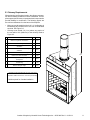
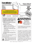
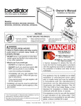
Owner’s Manual
Installation and Operation
Models:
Outdoor Woodburning
Castlewood 42
DO NOT DISCARD THIS MANUAL
• Important operating • Read, understand
and follow these
and maintenance
instructions for safe
instructions included.
installation and
operation.
WARNING
If the information in these instructions is not followed exactly, a
fire may result causing property
damage, personal injury, or death.
• Do not store or use gasoline or other flammable vapors and liquids in the vicinity of
this or any other appliance.
• Do not overfire. Overfiring will void your
warranty.
• Comply with all minimum clearances to
combustibles as specified. Failure to
comply may cause house fire.
WARNING: For Outdoor Use Only.
Installation and service of this fireplace should
be performed by qualified personnel. Hearth
& Home Technologies suggests NFI certified
or factory-trained professionals, or technicians
supervised by an NFI certified
professional.
T
O
N RD
O A
D SC
I
D
CAUTION
• Leave this manual with
party responsible for
use and operation.
WARNING
HOT SURFACES!
Glass and other surfaces are hot during
operation and cool down.
Hot glass will cause burns.
• Do not touch glass until it is cooled
• NEVER allow children to touch glass
• Keep children away
• CAREFULLY SUPERVISE children in same room as
appliance.
• A l e r t c h i l d r e n a n d a d u l t s t o h a z a r d s o f h i g h
temperatures.
High temperatures may ignite clothing or other
flammable materials.
• Keep clothing, furniture, draperies and other combustibles
away.
WARNING
Fire Risk
• For use with solid wood fuel or decorative
gas appliance only.
• Do not install unvented gas logs.
Outdoor Lifestyles by Hearth & Home Technologies Inc. • 4070-300 Rev H • 11/20/14
1
Read this manual before installing or operating this fireplace.
Please retain this owner’s manual for future reference.
Congratulations!
Congratulations on selecting a Outdoor Lifestyles wood
burning fireplace. The Outdoor Lifestyles fireplace you have
selected is designed to provide the utmost in safety, reliability
and efficiency.
As the owner of a new fireplace, you’ll want to read and
carefully follow all of the instructions contained in this owner’s
manual. Pay special attention to all cautions and warnings.
The information contained in this owner’s manual unless noted
otherwise, applies to all models and gas control systems.
Your new Outdoor Lifestyles wood burning fireplace will give
you years of durable use and trouble-free enjoyment. Welcome
to the Outdoor Lifestyles family of fireplace products!
This owner’s manual should be retained for future reference.
We suggest you keep it with your other important documents
and product manuals.
Homeowner Reference Information
We recommend that you record the following pertinent
information about your fireplace:
Model Name: Date purchased/installed: Serial Number: Location on fireplace: Dealership purchased from: Dealer phone: Notes: Listing Label Information/Location
The model information regarding your specific fireplace can be found on the rating plate located on the smoke shield of the
fireplace.
Grate
Serial
Number
FIREPLACE NO.
WARNING: RISK OF
FIRE DAMAGE. REPLACE
GRATE WITH HEARTH & HOME
TECHNOLOGIES INC.
Fireplace
Model
MODEL NO.
MODEL NO.
MFG. DATE
OUTDOOR FIREPLACE INTENDED FOR USE WITH HEARTH & HOME TECHNOLOGIES INC. LISTED FIREPLACE PARTS. SEE INSTALLATION AND
OPERATING INSTRUCTIONS FOR THIS MODEL. ONLY HEARTH & HOME TECHNOLOGIES INC. GLASS DOOR KITS CAN BE INSTALLED ON THIS UNIT.
FIREPLACE ALSO FOR USE
IN MANUFACTURED HOMES
YES
FAN KIT
MODEL NO.
CLEARANCE TO
COMBUSTIBLES:
NO
&
DO NOT OVERFIRE. USE ONLY: SOLID WOOD FUEL OR
LISTED DECORATIVE GAS APPLIANCE. DO NOT USE A
FIREPLACE INSERT OR OTHER PRODUCTS NOT
SPECIFIED FOR USE WITH THIS PRODUCT. IF DOORS
ARE USED OPERATE FIREPLACE WITH DOORS FULLY
OPEN OR CLOSED ONLY. WHEN BURNING A
DECORATIVE GAS APPLIANCE IN THE FIREPLACE,
ADJUST DAMPER TO THE FULLY OPEN POSITION.
CHIMNEY
2 IN. MIN.
IN.
MIN.
FIREBOX
RATED AT
115 VOLTS, 50/60 Hz.,
AMP.
WARNING! THIS FIREPLACE HAS NOT BEEN TESTED WITH AN UNVENTED
GAS LOG SET. TO REDUCE THE RISK OF FIRE OR INJURY, DO NOT
INSTALL AN UNVENTED GAS LOG SET INTO FIREPLACE.
WARNING! TO AVOID THE RISK OF DAMAGING FIREPLACE MATERIALS
AND INCREASING THE RISK OF SPREADING A FIRE DO NOT USE THE
FIREPLACE TO COOK OR WARM FOOD.
IF INSTALLATION OR OPERATING INSTRUCTIONS ARE MISSING
CONTACT: HEARTH & HOME TECHNOLOGIES INC.,
1915 W. SAUNDERS ST., MT. PLEASANT, IA 52641.
2
Outdoor Lifestyles by Hearth & Home Technologies Inc. • 4070-300 Rev H • 11/20/14
1
Listing and Code Approvals
2
Getting Started
Table of Contents
A. Appliance Certification. . . . . . . . . . . . . . . . . . . . . . . . . 4
A. Design and Installation Considerations. . . . . . . . . . . . 5
B. Non-Combustible Materials. . . . . . . . . . . . . . . . . . . . . 5
C. Combustible Materials . . . . . . . . . . . . . . . . . . . . . . . . . 5
D. Tools and Supplies Needed . . . . . . . . . . . . . . . . . . . . . 5
E. Inspect Fireplace and Components . . . . . . . . . . . . . . . 6
F. Grate. . . . . . . . . . . . . . . . . . . . . . . . . . . . . . . . . . . . . . . 6
G. Firescreen. . . . . . . . . . . . . . . . . . . . . . . . . . . . . . . . . . . 6
H. Cooling Air . . . . . . . . . . . . . . . . . . . . . . . . . . . . . . . . . . 6
I. Molded Brick Panel. . . . . . . . . . . . . . . . . . . . . . . . . . . . 6
3
Framing and Clearances
4
Installation of Fireplace
5
Chimney Assembly
6
Complete the Enclosure
7
Installation of Molded Brick Panel
A.
B.
C.
D.
E.
Selecting Fireplace Location. . . . . . . . . . . . . . . . . . . . 7
Clearances . . . . . . . . . . . . . . . . . . . . . . . . . . . . . . . . . 9
Sidewalls/Surrounds. . . . . . . . . . . . . . . . . . . . . . . . . 10
Frame the Fireplace . . . . . . . . . . . . . . . . . . . . . . . . . 10
Chimney Requirements. . . . . . . . . . . . . . . . . . . . . . . 11
11Troubleshooting
A. Diagnostics and Problem Solving. . . . . . . . . . . . . . . . 31
12 Maintenance and Servicing the Fireplace
A.
B.
C.
D.
E.
Disposal of Ashes . . . . . . . . . . . . . . . . . . . . . . . . . . . 32
Chimney Inspection/Cleaning. . . . . . . . . . . . . . . . . . 32
Firebox Refractory. . . . . . . . . . . . . . . . . . . . . . . . . . . 32
Maintenance Task List. . . . . . . . . . . . . . . . . . . . . . . . 33
Chimney Fire. . . . . . . . . . . . . . . . . . . . . . . . . . . . . . . 33
13 Reference Materials
A. Fireplace Dimensions. . . . . . . . . . . . . . . . . . . . . . . . . 34
B. Optional Components. . . . . . . . . . . . . . . . . . . . . . . . . 35
C. Chimney Components . . . . . . . . . . . . . . . . . . . . . . . . 36
D. Termination caps. . . . . . . . . . . . . . . . . . . . . . . . . . . . . 38
► E. Service Parts List . . . . . . . . . . . . . . . . . . . . . . . . . . . . 39
F. Limited Warranty . . . . . . . . . . . . . . . . . . . . . . . . . . . . 41
G. Contact Information . . . . . . . . . . . . . . . . . . . . . . . . . . 43
A. Secure the Fireplace. . . . . . . . . . . . . . . . . . . . . . . . . 12
B. Install Cooling Air Hoods. . . . . . . . . . . . . . . . . . . . . . 13
A. Chimney Requirements . . . . . . . . . . . . . . . . . . . . . . . 14
B. Assemble the Chimney Sections . . . . . . . . . . . . . . . . 15
C. Using Offsets/Returns. . . . . . . . . . . . . . . . . . . . . . . . . 16
A. Chimney Termination . . . . . . . . . . . . . . . . . . . . . . . . . 17
B. Chase Top. . . . . . . . . . . . . . . . . . . . . . . . . . . . . . . . . . 17
C. Install the Termination Cap. . . . . . . . . . . . . . . . . . . . . 17
A. Install Hearth Molded Brick Panel. . . . . . . . . . . . . . . . 19
B. Install Back Molded Brick Panel. . . . . . . . . . . . . . . . . 19
C. Install Side Molded Brick Panel . . . . . . . . . . . . . . . . . 19
D. Install Screens . . . . . . . . . . . . . . . . . . . . . . . . . . . . . . 20
E. Mortar (Optional). . . . . . . . . . . . . . . . . . . . . . . . . . . . . 20
8Accessories
A. Gas Log/Lighter Provisions. . . . . . . . . . . . . . . . . . . . 21
9Finishing
A. Non-combustible Materials. . . . . . . . . . . . . . . . . . . . . 22
B. Combustible Materials . . . . . . . . . . . . . . . . . . . . . . . . 22
C. Hearth Extension . . . . . . . . . . . . . . . . . . . . . . . . . . . . 22
D. Raised Hearth Extension Framing. . . . . . . . . . . . . . . 23
E. Non-combustible Sealant. . . . . . . . . . . . . . . . . . . . . . 24
F. Finishing Material . . . . . . . . . . . . . . . . . . . . . . . . . . . . 25
G. Mantel . . . . . . . . . . . . . . . . . . . . . . . . . . . . . . . . . . . . . 26
10 Operating Instructions
A. General Information. . . . . . . . . . . . . . . . . . . . . . . . . . . 27
B. Grate . . . . . . . . . . . . . . . . . . . . . . . . . . . . . . . . . . . . . . 27
C. Clear Space Near the Fireplace . . . . . . . . . . . . . . . . . 28
D. Firescreen. . . . . . . . . . . . . . . . . . . . . . . . . . . . . . . . . . 28
E. Glass Doors. . . . . . . . . . . . . . . . . . . . . . . . . . . . . . . . . 28
F. Wood Fuel . . . . . . . . . . . . . . . . . . . . . . . . . . . . . . . . . . 29
G. Starting a Fire . . . . . . . . . . . . . . . . . . . . . . . . . . . . . . . 30
Outdoor Lifestyles by Hearth & Home Technologies Inc. • 4070-300 Rev H • 11/20/14
3
1
Listing and Code Approvals
A.Appliance Certification
This fireplace system has been tested and listed in accordance with UL 127 and CAN/ULC-S610-M87 standards by
Underwriters Laboratories Inc. for installation and operation
in the United States and Canada. This fireplace has been
tested and listed for use with the optional components specified in this manual. These optional components may be purchased separately and installed at a later date.
Outdoor Lifestyles is a registered trademark of Hearth &
Home Technologies Inc.
WARNING
Improper installation, adjustment, alteration, service
or maintenance can cause injury or property damage.
Refer to the owner’s information manual provided with
this fireplace. For assistance or additional information
consult a qualified installer, service agency or your
dealer.
Not intended for use as a primary heat source.
This fireplace is tested and approved as a decorative
fireplace. It should not be factored as a primary heat
source in residential heating calculations.
WARNING
Fire Risk
• Do not install or operate damaged fireplace.
• Do not modify fireplace.
• Installation other than as instructed by Hearth & Home
Technologies Inc. is strictly prohibited.
• Do not operate the fireplace without fully assembling
all components.
• Do not overfire.
• THIS FIREPLACE HAS NOT BEEN TESTED FOR USE
WITH UNVENTED GAS LOGS. TO REDUCE RISK OF
FIRE OR INJURY, DO NO INSTALL AN UNVENTED
GAS LOG SET INTO THIS FIREPLACE
• Installation and/or use of any component part not
approved by Hearth & Home Technologies.
WARNING
Fire Risk
• WARNING! TO AVOID THE RISK OF DAMAGING
FIREPLACE MATERIALS AND INCREASING THE
RISK OF SPREADING A FIRE, DO NOT USE THE
FIREPLACE TO COOK OR WARM FOOD.
Hearth & Home Technologies disclaims any responsibility
for, and the warranty and agency listing will be voided by
the above actions.
4
Outdoor Lifestyles by Hearth & Home Technologies Inc. • 4070-300 Rev H • 11/20/14
2
Getting Started
A.Design and Installation Considerations
CAUTION
Check building codes prior to installation.
• Installation MUST comply with local, regional,
state and national codes and regulations.
• Consult insurance carrier, local building inspector,
fire officials or authorities having jurisdiction about
restrictions, installation inspection, and permits.
When planning a fireplace installation, it is necessary to determine the following information before installing:
B. Non-Combustible Materials
Materials which will not ignite and burn, composed of any
combination of the following:
- Steel
-Iron
- Brick
-Tile
-Concrete -Slate
-Glass
-Plasters Materials reported as passing ASTM
R 136, Standard Test Method for Behavior of Metals, in a
Vertical Tube Furnance aat 750° C
C. Combustible Materials
Materials made of or surfaced with any of the following
materials:
• Where the fireplace is to be installed. See Sections
3 and 4.
• The vent system configuration to be used. See Sections
5 and 6.
• Framing and finishing details. See Sections 3, 6 and 8.
• Whether optional accessories are desired. See
Section 12.
D. Tools and Supplies Needed
Moisture Resistance:
Before beginning the installation be sure the following tools and building supplies are available:
This outdoor fireplace will shed moderate amounts of water,
but is not waterproof. Water and condensing water vapor
may enter the chase under certain conditions.
-Wood -Compressed paper
-Plant fibers -Plastic
Any material that can ignite and burn; flame proofed or
not, plastered or un-plastered.
Reciprocating Saw
Framing material
Pliers
High temp caulking material
The fireplace will not perform as an exterior wall. Moisture
penetration must be considered for construction that places
the fireplace in structure walls or on moisture sensitive surfaces.
Hammer Gloves
When installed on exterior walls: Hearth & Home Technologies recommends that the fireplace chase be constructed outside the structure’s weather envelope. Where
the platform meets the wall, use a flashing detail similar to
that required for attached decks. Chase platforms, including
hearths should slope away from the structure at 1/8 in. to
1/4 in. per foot. The fireplace can be shimmed level.
Plumb line Safety glasses
Level
Tape measure
When installed on surfaces where water may collect or
cause damage: Hearth & Home Technologies recommends
that a drainage pan be placed under the unit. This can be
constructed of metal, adhesive polymer membrane (such as
ice and water shield) or other suitable materials. A means of
drainage out of the pan such as tubes or weep holes should
be provided. A slope of 1/8 in. to 1/4 in. per foot towards
the drain port is suggested. The fireplace can be shimmed
level.
Phillips screwdriver
Framing square
Flat blade screwdriver Electric drill and bits
1/2-3/4 in. lenght, #6 or #8 self-drilling screws
Misc. screws and nails
Read all the instructions before starting the
installation. Follow these instructions carefully
during the installation to ensure maximum safety
and benifit.
Hearths should slope away from the front of the fireplace
and chase at 1/8 in. to 1/4 in. per foot. Spark strips must be
on top of any combustible hearth materials used for moisture
management.
Outdoor Lifestyles by Hearth & Home Technologies Inc. • 4070-300 Rev H • 11/20/14
5
E.Inspect Fireplace and Components
WARNING
Fire Risk
Explosion Risk
Inspect fireplace and components for
damage. Damaged parts may impair safe
operation.
• Do NOT install damaged components.
• Do NOT install incomplete components.
• Do NOT install substitute components
I. Molded Brick Panel
•
•
•
The molded brick panels are shipped separately, but
required to contain heat and provide an attractive interior.
They will deteriorate over time and will need occasional
replacement. Small hairline cracks and discoloration are
normal and do not affect safety.
Mortar is not necessary but can be used to enhance the
appearance.
• Carefully remove the fireplace and components from the
packaging.
The fireplace system consists of the following:
• Fireplace / Integral grate/dual cooling air inlet hoods, firescreen, and hearth refractory.
F. Grate
This fireplace is designed to be used with the grate supplied with this unit or one approved by HHT. The grate will
deteriorate over time and will need occasional replacement.
Warning! Risk of Fire!
Use only the factory-supplied intergral grate.
Keep logs in place.
Allows proper air circulation around the fire.
G. Firescreen
The firescreen is provided to control sparks. Keep it
closed when the fireplace is in use.
WARNING! Risk of Fire or Burns!
Screen will not prevent burning materials from
falling out.
Screen pulls or handles may be hot.
H. Cooling Air
Cooling air is necessary to install the fireplace on a combustible surface and in a combustilbe enclosure. Two inlet
hoods are provided and must be installled, to allow cooling
air to be drawn into the enclosure. Ducting between the
hoods and the fireplace is not necessary.
The complete structure must be noncombustible if the hoods
are not installed.
6
Outdoor Lifestyles by Hearth & Home Technologies Inc. • 4070-300 Rev H • 11/20/14
3
Framing and Clearances
WARNING
Note:
• Illustrations and photos reflect typical installations
and are FOR DESIGN PURPOSES ONLY.
• Illustrations/diagrams are not drawn to scale.
• Actual installation/appearance may vary due to
individual design preference.
• Hearth & Home Technologies reserves the right to
alter its products.
Fire Risk
Provide adequate clearances.
• Around air openings
• To combustibles
• For service access.
Locate fireplace away from traffic areas.
A.Selecting Fireplace Location
This outdoor fireplace will shed moderate amounts of water,
but is not waterproof. Water and condensing water vapor
may enter the chase under certain conditions.
The fireplace will not perform as an exterior wall. Moisture
penetration must be considered for construction that places
the fireplace against structure walls or on moisture sensitive
surfaces.
• Exterior Walls (see Figure 3.1)
Hearth & Home Technologies recommends that the
fireplace chase be constructed outside the structure’s
weather envelope. Where the platform meets the wall, use
a flashing detail similar to that required for attached decks.
Chase platforms, including hearths, should slope away
from the structure at 1/8 in. to 1/4 in. per foot. The fireplace
can be shimmed level. Build the outside enclosure out of
standard building materials, being careful to maintain the
minimum air clearances specified in these installation
instructions.
•
Freestanding Installations (see Figure 3.2)
When installing this fireplace as a freestanding fireplace in
your yard, it must be enclosed to prevent impact damage
to the fireplace.
• Porch and Patio Installations
The fireplace will not perform as an exterior wall. Hearth & Home Technologies recommends that the fireplace
chase be constructed outside the structure’s weather
envelope. Where the platform meets the wall, use a
flashing detail similar to that required for attached decks.
Chase platforms, including heaths should slope away from
the structure at 1/8 in. to 1/4 in. per foot. The fireplace can
be shimmed level.
• The cooling air hoods MUST be used if installing in
a combustible enclosure. Ducting is not necessary
between the hoods and the fireplace.
• If fireplace is installed on cement and totally enclosed with
non combustilbe materials (i.e. metal studs, cement board,
etc.) the cooling air hoods do not need to be installed.
• When Installed on Surfaces Where Water May Collect
or Cause Damage:
Hearth & Home Technologies recommends that a drainage
pan be placed under the unit. This can be constructed
of metal, adhesive polymer membrane (such as ice
and water shield) or other suitable materials. A means
of drainage out of the pan such as tubes or weep holes
should be provided. A slope of 1/8 in. to 1/4 in. per foot
towards the drain port is suggested. The fireplace can
be shimmed level. Hearths should slope away from the
front of the fireplace and chase at 1/8 in. to 1/4 in. per
foot. Spark strips must be used on top of any combustible
hearth materials used for moisture management.
Outdoor Lifestyles by Hearth & Home Technologies Inc. • 4070-300 Rev H • 11/20/14
7
Note: If this surface is inside the
building’s warm air enevelope...
...then this surface must be an exterior wall
system.
1-1/2
[ 38 ]
29
[ 737 ]
1-1/2
[ 38 ]
28-1/2
[ 724 ]
1/2
[ 13 ]
53
[ 1344 ]
1/2
[ 13 ]
54
[ 1369 ]
67-1/2
[ 1714 ]
1-1/2
[ 38 ]
1-1/2
[ 38 ]
1/2
[ 13 ]
53
[ 1346 ]
1/2
[ 13 ]
54
[ 1372 ]
95-1/2
[ 2424 ]
Figure 3.1 Fireplace Locations
CORNER INSTALL DIMENSIONS
10 ft
Min.
(Enclosed Fireplace)
FREESTANDING
INSTALLATION
(Combustible Structure)
Figure 3.2 Freestanding Fireplace Locations
8
Outdoor Lifestyles by Hearth & Home Technologies Inc. • 4070-300 Rev H • 11/20/14
B.Clearances
WARNING
Fire Risk
• Comply with all minimum clearances to combustibles as specified.
• Framing or finishing material used on the front of, or in front of, the
appliance closer than the minimums listed, must be constructed entirely
of noncombustible materials (i.e., steel studs, concrete board, etc.).
Failure to comply may cause fire.
0 in. to level of standoffs
1-1/2 to side and back
0 in.
Figure 3.3 Clearance to Combustible
1/2 in to framing
Outdoor Lifestyles by Hearth & Home Technologies Inc. • 4070-300 Rev H • 11/20/14
9
C.Sidewalls/Surrounds
• Locate adjacent combustible sidewalls a minimum of 24 in. (610 mm) from fireplace opening.
• Mantle leg, surround, stub wall, whether combustible or non-combustible, may be constructed as shown in Figure 3.4.
Note: Grid depicts 1 inch squares.
FLUSH
FRONT
BRICK
FRONT
42 in.
[1067 mm]
°a
ng
le
22 3/8 in.
[568 mm]
39
50
52-7/8 in.
(1343 mm)
°a
4 in.
[102 mm]
19 3/4 in.
[500 mm]
ng
le
18 1/2 in.
[470 mm]
24 in.
[610 mm]
24 in.
[610 mm]
Figure 3.4 Mantel Leg, Surround or Wall Projection (acceptable on both sides of opening)
D.Frame the Fireplace
Figure 3.4 shows typical framing using combustible materials (2x4 lumber shown). Cooling air hoods required If total structure is non-combustible, cooling air hoods are not necessary.
• Observe all required air space clearances to combustible materials as shown in Figure 3.5.
2 in./51 mm
minimum air
space clearance
to the enclosure.
Metal framing stud to provide support and backing for
wall material and mantel.
area to be covered with nonccombustible material.
A
28-3/8 in.
721 cm
74- 1/2 in.
1892 cm
53-7/8 in.
1368 cm
Figure 3.5 Framing the Fireplace
10
Outdoor Lifestyles by Hearth & Home Technologies Inc. • 4070-300 Rev H • 11/20/14
E.Chimney Requirements
When planning your fireplace location, the chimney construction and necessary clearances must be considered. The fireplace system and chimney components have been tested to
provide flexibility in construction. The following figures are
the minimum distances from the base of the fireplace.
• Minimum overall straight height is 10 ft If the fireplace is
freestanding and a minimum of 10 ft from a combustible
structure. See Figure 3.2.
• Chimney must extend 2 ft (.6 m) above any portion of
the roof within 10 ft (3048 mm) of the chimney. Refer to
Figure 6.2.
ft
m
Minimum height with offset/return
14.5
4.42
•
Maximum height
90
27.43
•
Maximum chimney length between an offset
and return
20
6.1
•
Maximum distance between chimney
stabilizers
35
10.67
•
Double offset/return minimum height
24
7.32
•
Maximum unsupported chimney length
between the offset and return
6
1.83
35
10.67
•
• Maximum unsupported chimney height above
the fireplace
•
Minimum overall straight height if fireplace is
freestanding
6.4
1.95
•
Minimum Straight Height
14.5
4.42
91/2 ft
* Transition section standard with unit and 1 foot section
required in addtion as minimum or SLA10 (for Canada)
CAK8A required for Canada installation
Outdoor Lifestyles by Hearth & Home Technologies Inc. • 4070-300 Rev H • 11/20/14
11
4
Installation of Fireplace
A. Secure the Fireplace
•
Place the Protective Metal Hearth Strips
Position the Fireplace
This fireplace may be placed on either a combustible
or noncombustible continouous flat surface. Follow the
instructions for framing in Section 3.D. Slide the fireplace
into position. Be sure to provide the minimum air clearance at the sides and back of the fireplace assembly. See
Section 3.B.
WARNING
1 in. (25 mm)
overlap
FIre Risk! Prevent contact with sagging, loose insulation.
Do NOT instal against vapor barriers or exposed insulation.
Cooling Air Hoods must be installed if instaling on a combustible surface.
Level the Fireplace
Level the fireplace side-to-side and front‑to‑back. Shim with
noncombustible material, such as sheet metal, as necessary. Secure the fireplace (using the nailing flanges located
on either side of the fireplace) to the vertical framing.
Note: When elevating the fireplace above the hearth
extension the front of the elevated platform must be
protected with a protective metal hearth strip.
Important: To ensure proper fit of the glass doors, check
the fireplace opening for square. Measure diagonal
distances of the opening to make sure they are equal.
If they are not, continue to shim the fireplace until those
diagonals are equal.
Protective metal strips are placed 2 in. (51 mm) under the
front of the fireplace and must extend beyond the front
and sides of fireplace opening by 2 in. (51 mm).
Figure 4.1 Position the Protective Metal Hearth Strips
Included with your fireplace you will find two metal hearth strips
measuring approximately 26 in. x 4 in. (660 mm x 102 mm).
These strips are used to provide added protection where the
fireplace and the hearth extension meet when installed on
a combustible service.
Slide each metal strip 2 in. (51 mm) under the front edge of
the fireplace. The individual pieces must overlap each other
by 1 in. (25 mm) minimum in the middle of the fireplace to
provide continuous coverage of the floor. See Figure 4.1.
These metal strips should extend from the front and sides of
the fireplace opening by 2 in. (51 mm).
WARNING
Fire Risk!
• Metal hearth strips MUST be installed.
Sparks or embers may ignite flooring.
Top piece must overlap
bottom piece
Raised Platform
2 in.
(51 mm)
1 in. (25 mm) min.
overlap
Floor
2 in.
(51 mm)
Figure 4.2 Protect the Front of an Elevated Platform
12
Outdoor Lifestyles by Hearth & Home Technologies Inc. • 4070-300 Rev H • 11/20/14
B. Install Cooling Air Hoods
WARNING! Cooling air must be provided when installing in combustible enclosure or on combustible surface.
• Locate cooling air hoods to prevent blockage from
leaves, snow/ice, or other debris. Blockages could
cause the unit to overheat.
• Recommended bottom of a 7-3/4” X 7-3/4” or 7-3/4”
diameter hole 12” above bottom of unit
• Do Not place cooling air hood close to exhaust vent.
• The outside air hood can be painted to match/accent
the color of the structure.
Caution! Risk of Fire or Asphyxiation! Do not draw outside air from wall, floor, or ceiling cavity, or enclosed
spaces such as an attic or garage.
Outdoor Lifestyles by Hearth & Home Technologies Inc. • 4070-300 Rev H • 11/20/14
13
5
Chimney Assembly
A. Chimney Requirements
WARNING
Vertical distances are measured from the base of the fireplace.
• Minimum overall straight height is 10 ft. if the fireplace is
freestanding and a minimum of 10 ft from a combustible
structure.
• Chimney must extend 2 ft (.6 m) above any portion of the
roof within 10 ft (3 m) of the chimney. To determine the
chimney components needed to complete your particular
installation, follow the steps below:
• Determine the total vertical height of the fireplace
installation. This dimension is measured from the base of
the fireplace assembly to the point where the smoke exits
the termination cap.
• Subtract the effective height of the fireplace assembly from
the overall height of the fireplace installation (measured
from the base of the fireplace to the bottom of the
termination cap).
• Refer to Table 5.1 to determine what components must
be selected to complete the fireplace installation.
• Determine the number of ceiling firestops, stabilizers,
roof flashing, etc. required to complete the fireplace
installation.
Fire Risk
Must maintain 2 in. (51 mm) air
clearance to insulation and other
combustible materials.
Warning: DO NOT PACK REQUIRED AIR
SPACES WITH INSULATION OR
OTHER MATERIALS.
CAUTION
• Do NOT connect this fireplace to a chimney flue
servicing another appliance.
• Do NOT connect to any air distribution duct or
system.
ft
m
•
Minimum height with offset/return
14.5
4.42
•
Maximum height
90
27.43
•
Maximum chimney length between an offset
and return
20
6.1
•
Maximum distance between chimney
stabilizers
35
10.67
•
Double offset/return minimum height
24
7.32
FS538
FS538
0
0
•
Maximum unsupported chimney length
between the offset and return
6
1.83
FS540
FS540
0
0
35
10.67
SL430
14-1/2
368
SL1106
SL406
4-3/4
121
SL1112
SL412
10-3/4
273
SL1118
SL418
16-3/4
425
SL1136
SL436
34-3/4
883
SL1148
SL448
46-3/4
1187
n/a
SLA10
16-3/4
425
• Maximum unsupported chimney height above
the fireplace
•
Minimum overall straight height if fireplace is
freestanding
6.4
1.95
•
Minimum Straight Height
14.5
4.42
* Transition section standard with unit and 1 foot section required in addtion as minimum
.
Table 5.1
HEIGHT OF CHIMNEY COMPONENTS
US
in.
mm
4-3/4
121
Canada ONLY
Chimney Stabilizer
SL11
SL4
Ceiling Firestops
Offsets/Returns
SL1130
Chimney Sections*
* Dimensions reflect effective height.
Note: A maximum of two pairs of offsets and returns may
be used.
14
Outdoor Lifestyles by Hearth & Home Technologies Inc. • 4070-300 Rev H • 11/20/14
B. Assemble the Chimney Sections
Warning! Risk of Fire! Do NOT install substitute or damaged chimney components.
• Use only those components described in this manual.
Substitute or damaged chimney components could impair
safe operation and cause overheating and fire.
• Support the pipe during construction and check to be sure
inadvertent loading has not dislodged the chimney section
from the fireplace or at any chimney joint.
• Attach the transition section to the top of the fireplace.
• Place inner flue to the inside of the chimney section below
it. Place the outer casing outside the outer casing of the
chimney section below it. Refer to Figure 5.1.
N o t ic e : C h i m n e y s e c t i o ns cann o t b e
disassembled once locked together. Plan
ahead!
• Lock chimney sections and/or offsets/returns together by
pushing downward until the top section meets the stop
bead on the lower section.
• Pull on the top section to make sure it is fully engaged
and will not separate.
• You may use #6 or #8 sheet metal screws no longer than
1/2 in. (13 mm) to fasten chimney sections together. Do
NOT penetrate inner flue.
•
Fiqure 5.1 Assembling Chimney Sections
Fasten offset/returns to chimney sections. Insert the
screws (provided) through the predrilled holes. Do
NOT penetrate inner flue.
• Secure chimney returns with hanger straps (provided);
fasten to studs or joists.
• Vertical straight runs of chimney must be supported every
35 ft (10.7 m).
Outdoor Lifestyles by Hearth & Home Technologies Inc. • 4070-300 Rev H • 11/20/14
15
C. Using Offsets/Returns
To bypass any overhead obstructions, the chimney may be
offset using an offset/return.
An offset and return may be attached together or a chimney
section(s) may be used between an offset and return.
Perform the following steps to determine the correct chimney component combination for your particular installation:
WARNING
Fire Risk
• Draft will be restricted if offsets/returns
greater than 30° are used.
Table 5.2
A
B
• Measure how far the chimney needs to be shifted to enable
it to avoid the overhead obstacle. See Figure 5.1. Use
dimension “A” to determine chimney section required to
achieve the needed shift.
• After determining the offset dimension, refer to Table 5.2
and find the “A” dimension closest to but not less than the
distance of shift needed for your installation.
• The “B” dimension that coincides with the “A” dimension
represents the required vertical clearance that is needed
to complete the offset and return.
• Read across the chart and find the number of chimney
sections required and the model number of those particular
chimney parts.
• Whenever the chimney penetrates a floor/ceiling, a ceiling
firestop must be installed.
• The effective height of the fireplace assembly is measured
from the base of the fireplace to the top of the starter collar.
See Dimensions in Section 12.
SL1106 SL1112 SL1118 SL1136 SL1148
SL406 SL412 SL418 SL436 SL448
in.
mm
in.
mm
4 7/8
124
17 7/8
454
-
-
-
-
-
7 1/4
184
22
559
1
-
-
-
-
9 3/4
248
26 1/8
664
2
-
-
-
-
10 1/4
260
27 1/4
692
-
1
-
-
-
12 3/4
324
31 3/8
797
1
1
-
-
-
13 1/4
337
32 3/8
822
-
-
1
-
-
15 3/4
400
36 5/8
930
-
2
-
-
-
18 1/8
460
40 3/4
1035
1
2
-
-
-
18 3/4
476
41 3/4
1060
-
1
1
-
-
21 3/4
552
47
1194
-
-
2
-
-
22 1/4
565
48
1219
-
-
-
1
-
24 3/4
629
52 1/8
1324
1
-
-
1
-
27 3/4
705
57 3/8
1457
-
1
-
1
-
28 1/4
718
58 3/8
1483
-
-
-
-
1
30 3/4
781
62 1/2
1588
1
-
-
-
1
33 3/4
857
67 3/4
1721
-
1
-
-
1
36 3/4
933
73
1854
-
-
1
-
1
39 3/4
1010
78 1/8
1984
-
-
-
2
-
41 1/8
1045
82 3/8
2092
1
-
-
2
-
45 3/4
1162
88 1/2
2248
-
-
-
1
1
48 1/8
1222
92 3/4
2356
1
-
-
1
1
51 3/4
1314
98 7/8
2511
-
-
-
-
2
Proper assembly of air cooled chimney parts results in an overlap of chimney joints
of 1-1/4 in. (32 mm). Effective length is built into this table.
16
A
B
1-1/4 in. (32 mm)
OVERLAP
Figure 5.2
Example: Your “A” dimension from Figure 5.2 is
14 1/2 in. (368 mm). Using Table 5.2 the dimension
closest to, but not less than 14 1/2 in. (368 mm) is
15 3/4 in. (400  mm) using a 30° offset/return. It is
then determined from the table that you would need
36 5/8 in. (930 mm) (Dimension “B”) between the
offset and return. The chimney components that
best fit your application are two SL1112s or SL412s.
Outdoor Lifestyles by Hearth & Home Technologies Inc. • 4070-300 Rev H • 11/20/14
6
Complete the Enclosure
A. Chimney Termination
Chimney Termination Requirements (see Figure 6.1)
•
Must have a cap approved and listed for this fireplace
system
•
Must not be located where it will become plugged by
snow or other material
•
Must terminate at least 3ft (914 mm) about the roof
and at least 2 ft (610mm) above any portion of the
roof within 10 ft. (305mm)
•
Must be located away from trees or other structures
C.Install the Termination Cap
Note: To protect against the effect of corrosion on those
parts exposed to the weather, the termination cap can be
painted with a rust-resistant paint.
WARNING
Fire Risk
• The minimum overlap of cap to pipe
MUST be met or chimney may separate
from cap.
Separation allows sparks, heat and embers
to escape.
Install the chimney sections up through the chase enclosure
and refer to termination cap instructions.
WARNING
Fire Risk
• Must maintain 2 in. (51 mm) air clearance
to insulation and other combustible
materials.
NOTE: TR11/TR444 Round Termination Cap and TR11T/
TR442 Round Telescoping Termination Cap not recommended for Installations less than 20 feet.
B. Chase Top
A metal chase top is required to seal the top of the chase
around the chimney pipe. The top should include a turndown and drip edge to prevent water from seeping into the
chase. Provide a 1/8 in. (3 mm) gap around the flue pipe and
slope the top downward away from the penetration.
ST1175/ST475 Square Termination Cap
• All seams must be caulked to prevent leaks.
•
•
A chase installation must use a chase top. Chase tops are available from your HHT dealer or may be field constructed.
Attach the chase top to the top of the chase.
Place waterproof
caulk or sealer under
each flange of the
termination cap and
on top of each screw
to help prevent leaks.
Flange
Termination Cap
2 in. (51 mm) Collar
on Chase Top
Collar
2 in. (51 mm)
Minimum Height
The last section of pipe
must stop between 2 in. (51
mm) above the top of the
chase and 4 3/4 in. (121
mm) below the top of the
chase.
Chase Top
2 in. (51 mm)
maximum
4 3/4 in. (121 mm)
maximum
Slope Downward
Chase
Turn-down
Drip Edge
.018 (26 ga) min. Galvanized Chase Top
Chimney
Pipe
Figure 6.1 Field Constructed Chase Top Specification
Termination cap pipe and chimney section must overlap 1-1/2 in. (38 mm)
Figure 6.2 Installing an ST1175/ST475 Square Termination Cap
Outdoor Lifestyles by Hearth & Home Technologies Inc. • 4070-300 Rev H • 11/20/14
17
TCT1175 Terra Cotta Cap
Place waterproof sealer
under each flange of the
termination cap and on
top of each screw to
help prevent leaks.
Remove 2 screws
from front & back
to lift the top off
Termination Cap
Collar
2 in. (51 mm)
Minimum Height
The last section of pipe
must stop between 2 in.
(51 mm) above top of
chase and 7 in. (178 mm)
below top of chase
Chase Top
2 in. (51 mm)
7 in. (178 mm)
Chase
Chimney
Pipe
Termination cap pipe and chimney section must overlap
1-1/2 in. (38 mm)
Figure 6.3 Installing a TCT1175 Square Termination Cap
18
Outdoor Lifestyles by Hearth & Home Technologies Inc. • 4070-300 Rev H • 11/20/14
7
Installation of Molded Brick Panel
A. Install Hearth Molded Brick Panel
1. Put a level on fireplace to verify it is level side to side and front to back.
2. While the hearth is removed from the fireplace , measure all 4 corrners to determine the variance from corner to
corner. See Figure 7.1.
3. Shim the low corners of the hearth refractory by installing
the metal pieces provided on the fireplace bottom. See Figure 7.2. 4. Put a level on the top flange of the refractory and shim as
necessary from side to side or front to back. See Figure
7.3.
Note: The top flange of the hearth should be level to allow
the sides and back to be installed with minimal gaps. The
hearth slopes towards the front of the unit approximately
1/4”.
B. Install Back Molded Brick Panel
•
•
•
•
Refer to Figure 7.4.
Set the grate retainer in place, in the notch in the hearth. Install the back panel. Center from side to side.
Install rear refractory retainer.
Side Refractory Retainer
Back Refractory Retainer
Back Molded Brick Panel
Side Refractory Retainer
Left Side Molded Brick Panel
Grate Retainer
Gas tube locator dimple
Right Side Molded Brick Panel
Figure 7.1.
Hearth Retainer
Figure 7.4
C. Install Side Molded Brick Panel
Figure 7.2.
•
Remove screen rods.
•
Remove smoke shield
•
Install side panel by lifting up, setting on top flange of
hearth and slide towards back of unit until it meets up
with back panel.
•
Install refractory retainer •
Install second side panel following the steps above.
Replace the smoke shield.
•
Install refractory retainer.
Figure 7.3.
Outdoor Lifestyles by Hearth & Home Technologies Inc. • 4070-300 Rev H • 11/20/14
19
F. Grate
D. Install Screens
•
Lay one screen panel flat and slide the round end of
the rod through the rings starting at the handle side of
the screen. Leave the last ring off the rod.
•
Insert the rod through the hole in the bracket. Slip the
last ring over the rod on the other side of the bracket.
•
Fasten the flat end of the screen rod back in place using the screw removed earlier.
•
Repeat for the other screen panel
•
Install the grate If a gas log set
is not going to be installed.
•
Position the rear grate bar in the
Grate Retainer
•
Position the top of the grate
retainer over the rear grate bar
and fasten in place with screw
provided.
Round end of Rod through rings,
then into Screen Rod Clip
Top of Fireplace
Center of Fireplace Opening
Rod Screen
Clip
E.
Inside
Firebox
Mortar (Optional)
The brick panels have been designed for installation without the use of mortar being necessary. If the
look of mortar is preferred, it is available and can be
installed. Follow the directions on the container for mixing.
The mortar can be applied with a mortar bag or trowled
on. Applying with mortar bag may be easiest and less
messy. Clean sparingly as paint will rub off and may
need to be touched up. Touch up paint is available as
an accessory.
VERY IMPORTANT: Allow the mortar 72 hours to cure before operating the fireplace.
If Mortor is applied, it should be
applied after finishing material is
installed. Mortar will be applied
between finishing materials and
molded brick edges, bottom and
sides.
The seam between finishing materials
and firebox top must be sealed with
non-combustible sealant.
The non-combustible finishing
material across the top of
fireplace opening will be even
with lower edge of metal face.
Non-combustible finishing
materials MUST overlap
side faces by 1 1/4 in. (32 mm)
to cover the edges of the
panels. Finished opening
should be 38 x 42 in. (965 x
1067 mm) to allow for door
installation.
The surface of the finished hearth extension and
the surface of the hearth panel should be level.
Figure 7.5 Facing Materials and Mortar
20
Outdoor Lifestyles by Hearth & Home Technologies Inc. • 4070-300 Rev H • 11/20/14
8
Accessories
A.Gas Log/Lighter Provisions
A certified gas log lighter or decorative gas log set can be
installed in this fireplace.
This fireplace was not tested and listed for use with an unvented gas log heater. Do not install an unvented gas log
heater in this fireplace and operate it with the flue damper in
the closed position unless the unvented gas log heater has
been specifically tested and listed for use in this fireplace by
Underwriters Laboratories Inc.
Use of an unvented gas log heater in this factory built
fireplace may create a fire hazard that can result in a
structure fire.
• Maximum input is 100,000 BTU/hr.
• Decorative gas appliance must be certified to ANSI Z21.60
“Standard for Decorative Gas Appliances for Installation
in Vented Fireplaces”.
• Must be installed in accordance with the National Fuel
Gas Code, ANSI Z223.1.
• A log set must incorporate a gas shutoff.
• Log set requires the damper to be locked fully open.
• A locating dimple is on both sides of the hearth refractory.
Determine if a gas line is necessary and drill with a 1” in.
masonry bit. Drill parallel with the back of the fireplace.
• We recommend you seal refractory around pipe with
fireplace mortar or high temperature, noncombustible
sealant.
• Repack insulation from the knockout around the pipe.
• Maintain 1-1/2 in. (38 mm) air space around the pipe for
4 in. (102 mm) beyond the fireplace.
• See Figure 8.1.
Firebox
WARNING
Asphyxiation Risk
• Damper must be locked open when gas logs
installed.
Gas fire generates fumes.
WARNING
Fire Risk
• For use with solid wood fuel or decorative
gas appliance only.
• DO NOT install unvented gas logs.
WARNING
Fire Risk
Explosion Risk
Inspect appliance and components for
damage. Damaged parts may impair safe
operation.
• Do NOT install damaged components.
• Do NOT install incomplete components.
• Do NOT install substitute components
Report damaged parts to dealer.
Outer shell
of fireplace
Maintain air clearance
to combustibles.
Refractory
Combustible
materials
Seal with
fireplace mortar
or non-combustible sealant
Gas line
Repack
insulation
knockout
Gas line
4 in.
(102 mm)
1 1/2 in. (38 mm)
air space around
pipe
Combustible materials
may be located at zero
clearance to gas line
beyond 4 in. (102 mm)
from fireplace side.
Figure 8.1 Gas Line Installation
Outdoor Lifestyles by Hearth & Home Technologies Inc. • 4070-300 Rev H • 11/20/14
21
9
Finishing
A. Non-combustible Materials
• Materials which will not ignite and burn, composed of any
combination of the following:
- Steel
- Iron
- Brick
- Tile
- Concrete
- Slate
- Glass
- Plasters
• Materials reported as passing ASTM E 136, Standard
Test Method for Behavior of Metals, in a Vertical Tube
Furnace at 750° C
B. Combustible Materials
• You MUST use a hearth extension with this fireplace.
• This fireplace has been tested and approved for use with a
hearth extension insulated to a minimum R value of 2.32.
• The hearth extension material MUST be covered with tile,
stone or other non-combustible material.
• Manufactured hearth materials will usually have a
published R value (resistance to heat) or k value
(conductivity of heat). Refer to the formula in Table 12.1
to convert a k value to an R value,
• Refer to Table 12.2 for hearth extension insulation
alternatives.
• Materials made of or surfaced with any of the following
materials:
- Wood
- Compressed paper
- Plant fibers - Plastic
• Any material that can ignite and burn; flame proofed or
not, plastered or un-plastered
Surfaces must be
covered with non
combustible material
C. Hearth Extension
WARNING! Risk of fire! High temperatures, sparks, embers or other burning material falling from the fireplace may
ignite flooring or concealed combustible surfaces.
• Metal hearth strips MUST be installed (Section 7.C.).
• Hearth extensions MUST be installed exactly as
specified.
Table 12.1
12 in.
(305 mm)
42 in.
(1067 mm)
12 in.
(305 mm)
66 in.
(1676 mm)
Raised Platform
20 in. (508 mm) Minimum
Flush Hearth
30 in. (762 mm) Minimum
R = 1/k x inches of thickness
Table 12.2
Hearth Extension Insulation Alternatives-Total minimum R Value must equal 2.32
k per inch
thick
R per inch
thick
Minimum thickness required
Hearth & Home HX3, HX4 (Micore 300™)
0.49
2.06
1 in. (25.4 mm)
USG Micore 160™
0.39
2.54
1 in.(25.4 mm)
USG Durock™ Cement Board
1.92
0.52
4 in. (101.6 mm)
Cement Mortar
5.0
0.20
10 in. (254 mm)
Common Brick
5.0
0.20
10 in. (254 mm)
12.50
0.08
25-3/4 in. (654 mm)
Material
Ceramic Tile
Armstrong™ Privacy Guard Plus
Marble
22
0.46
2.18
1 in. (25.4 mm)
14.3 to 20.0
0.07 to 0.05
29-1/2 to 41 in. (749.3 to 1041.4 mm)
Outdoor Lifestyles by Hearth & Home Technologies Inc. • 4070-300 Rev H • 11/20/14
D. Raised Hearth Extension Framing
The hearth framing must be constructed of non-combustible
materials (Figure 12.2) and placed on 1/2 in. Durock and 1
in. Micore (or equivalent material) (Figure 12.4). When creating the platform, allow for the thickness of the non-combustible finishing materials (Figure 12.5).
IMPORTANT! Hearth extension design must be determined
before installation of fireplace.
Continuous,
non-combustible sealant
1 in. Micore or
equivalent insulation
(see Table)
Tile, stone or other
non-combustible material
Fireplace
Durock
*
Floor constructed of wood or
other combustible material
Protective
Metal Hearth
Strip
Non-combustible
Framing Material
*
* 2 in. (51 mm)
1 in. Micore or
equivalent insulation
& 1/2 in. Durock
Figure 12.4 Raised Platform Hearth Extension-Framing Materials
Figure 12.2
Note: The bottom of the
fireplace opening is 3-3/4 in.
(95.3mm) above the bottom of
the fireplace. Finished hearth
must NOT extend above this
level.
Bottom of
fireplace opening
20 in. Min.
Hearth Extension
Platform must be built
to raise the bottom of
the fireplace opening
to the level of the
desired hearth height.
Non-combustible
Finishing Material
Non-combustible
Finishing Materials
Figure 12.5 Raised Platform Hearth Extension-Finishing Materials
1 in. Micore or
equivalent insulation
& 1/2 in. Durock
Protective Metal
Hearth Strips
Floor
Non-combustible
Framing Material
Hearths should slope away from the front of the fireplace
and chase at 1/8 in. to 1/4 in. per foot. Spark strips must
be on top of any combustible hearth materials used for
moisture management.
Figure 12.3 Raised Platform Hearth Extension Detail
Outdoor Lifestyles by Hearth & Home Technologies Inc. • 4070-300 Rev H • 11/20/14
23
E. Non-combustible Sealant
After completing the framing and applying the facing materials over the framing, a bead of 300° F minimum noncombustible sealant or motar must be used to close off any
gaps at the top and sides between the fireplace and hearth.
Non-combustible Sealant
Figure 12.6 Place Non-combustible Sealant
Flush Hearth Extension Framing
• Fireplace must be recessed 3 3/4 in. (95.3 mm) below the
finished floor.
24
Outdoor Lifestyles by Hearth & Home Technologies Inc. • 4070-300 Rev H • 11/20/14
F. Finishing Material
Refer to Sections 9.A. and Sections 9.B. for combustible/
non-combustible materials. Refer to Figure 9.2 for non-combustible zone if cooling air hoods are installed.
Warning! Risk of Fire! You must maintain clearances.
• Use only non-combustible framing material below
standoffs.
• Sheetrock, wood or other combustibles must NOT be used
as sheathing or facing in the non-combustible zone.
• Do NOT cover metal fireplace front with combustible
materials.
• Install combustible materials only to specified clearances
on top front and side edges.
• Complete framing and apply facing material (drywall) over
framing.
• A bead of 300-deg F minimum non-combustible sealant
must be used to close off any gaps at the top and sides
between the fireplace and facing to prevent cold air leaks.
• Large gaps can be bridged with fiberglass rope gasket.
• Only non-combustible materials may be used to cover the
metal fireplace front.
WARNING! Risk of Fire! Use only non combustible
material when cooling hoods are not installed.
These surfaces
must be covered
with non-combustible
material.
Non-combustible
sealant.
Figure 9.1 Non-combustible Facing
Note: We recommend mortar be applied after
facing materials are installed. Refer to Section 7.E
2 x 4 stud wall
Finished combustible wall
2 x 4 header, flush with
front of stand-offs
Non-Combustible material
Non-combustible
decorative facing
(up to full brick depth)
Continuous,
non-combustible sealant
Tile, stone or other
non-combustible material
1 in. Micore
or equivilent
insulation &
1/2 in. Durock
Hearth
Refractory
Metal strips are placed 2 in. (51 mm)
under the front of the fireplace and must
extend beyond the front and sides of
fireplace opening by 2 in. (51 mm)
Bottom of fireplace opening
and finished hearth may be
the same height
Floor constructed of wood or
other combustible material
Figure 9.2 Decorative Facing
Outdoor Lifestyles by Hearth & Home Technologies Inc. • 4070-300 Rev H • 11/20/14
25
G.Mantel
•
•
•
•
•
Refer to the shaded areas of Figure 9.3 for the location and dimensions of a combustible mantel.
A combustible mantel may be positioned no lower than 22 in. (508 mm) above the top of the fireplace opening.
A combustible mantel may have a maximum depth of 12 in. (305 mm).
Combustible trim and materials cannot be placed within 6 in. (152mm) of the fireplace opening (top or sides).
Combustible materials projecting more than 1 1/2 in. (38 mm) shall not be placed within 12 in. (305 mm) from the top of
the fireplace opening.
• Combustible trim must not cover the metal surfaces of the fireplace.
• Mantel clearance is in accordance with Section 7-3.3.3 of ANSI/NFPA211.
Combustible Wall
Combustible
Decorative Facing
7 ft (2134 mm)
minimum
base of fireplace
to ceiling
2 x 4 stud wall
Grid represents
1 in. squares
Metal support to stablize wall and mantel
Standoffs
12 in./305 mm
Mantel
22 in./559 mm
minimum
Non-combustible
Decorative Facing
such as:
Steel, iron, brick,
tile, concrete, slate,
glass, plasters.
Seal joint with
non-combustible
sealant
12 in./305 mm
minimum
6 in./152 mm
minimum
1 1/2 in./
38 mm
maximum
Measured from top of fireplace opening
Figure 9.3 Clearance to Mantel or other non-combustilbes above fireplace
26
Outdoor Lifestyles by Hearth & Home Technologies Inc. • 4070-300 Rev H • 11/20/14
10
Operating Instructions
WARNING
Fire Risk
• Do not operate fireplace before reading
and understanding operating instructions.
Failure to operate fireplace properly may
cause fire.
A.General Information
Fireplaces, as well as other woodburning appliances, have
been used safely for many years. It has been our experience
that most problems are caused by improper installation and
operation of the fireplace. Make certain that installation and
operation of the fireplace system is in accordance with these
instructions.
It is extremely important that the fire be supervised whenever the fireplace is in use. It is also recommended that an
annual inspection be performed on the fireplace system to
determine if the flue system needs to be cleaned, or as in
the case of any appliance, if minor repairs are required to
maintain the system in top operating condition.
B.Grate
The factory installed integral grate must be used to hold the
logs from falling out of an open fireplace and to allow air to
pass between the burning logs. It is important to keep the
fire off the hearth and to allow the ashes to collect beneath
the fire, thereby forming a layer of additional heat protection.
WARNING
HOT SURFACES!
Glass and other surfaces are hot during
operation and cool down.
Hot glass will cause burns.
• Do not touch glass until it is cooled
• NEVER allow children to touch glass
• Keep children away
• CAREFULLY SUPERVISE children in same room as
appliance.
• Alert children and adults to hazards of high temperatures.
High temperatures may ignite clothing or other
flammable materials.
• Keep clothing, furniture, draperies and other combustibles
away.
WARNING
Fire Risk
• For use with solid wood fuel or decorative gas
appliance only.
• Do not install unvented gas logs.
WARNING
Fire Risk
• Use only factory installed integral grate.
May cause overfire.
Outdoor Lifestyles by Hearth & Home Technologies Inc. • 4070-300 Rev H • 11/20/14
27
C.Clear Space Near the Fireplace
D.Firescreen
Combustible materials must not be stored on the hearth extension. Outdoor room furnishings such as chairs or other
combustibles must be at least 4 ft (1.22 m) from the open
front of the fireplace.
A firescreen is always provided to control sparks. It must be
closed whenever the fireplace is in use. Glass doors or firescreens must not be used to hold burning material inside the
fireplace. Only those glass doors specifically tested and listed for use with the specific fireplace model should be used.
Screens should be closed when the glass doors are closed.
THERE IS NOT A FLUE DAMPER, THEREFORE UNIT
CANNOT BE INSTALLED INDOORS.
WARNING
Fire Risk
• Close firescreen when burning fireplace.
• Do not use firescreen or glass doors to
hold burning material in fireplace.
Firescreen controls sparks.
Glass may break or burning material may
roll out.
E.Glass Doors
Most efficient fireplace operation using glass doors is with
the doors open. When the doors are open the screen must
be closed. Only Hearth & Home Technologies glass doors
may be used. See Figure 10.1 for proper glass door operation.
FULLY OPEN
CORRECT
PARTLY OPEN
INCORRECT
FULLY CLOSED
CORRECT
PARTLY CLOSED
INCORRECT
Figure 10.1 Proper Operating Positions of Bi-fold Doors
WARNING
Fire Risk
Smoke Risk
• Doors must be fully opened or fully closed
when operating fireplace.
Partially opened doors may draw flame, smoke
or heat from fireplace.
28
Outdoor Lifestyles by Hearth & Home Technologies Inc. • 4070-300 Rev H • 11/20/14
F. Wood Fuel
Seasoning
Firewood
Your fireplace performance depends on the quality of the
firewood you use. All seasoned wood, regardless of species, contains about 8,000 BTU’s per pound, and hardwoods have a greater density than soft woods. A piece
of hardwood will contain about 60% more BTU’s than
an equal size piece of soft wood. Firewood is commonly
sold by the cord (128 cu. ft.). A cord of seasoned oak
(hardwood) would contain about 60% more potential energy than a cord of seasoned pine (soft wood).
Examples of soft wood trees are Douglas fir, pine, spruce,
and cedar, poplar, aspen and alder. Soft woods require
less time to dry, burn faster and are easier to ignite than
hardwoods.
Examples of hardwood trees are oak, maple, apple, and
birch. Hardwoods require more time to season, burn
slower and are usually harder to ignite than soft woods.
The best wood fuel is a combination of soft wood and
hardwood. Start the fire with soft wood; the fire will give
off quick heat to bring the fireplace up to operating temperature, and then the hardwood can be added for slow,
even heat and longer burn time.
Moisture
Regardless of which species of wood you burn, the single
most important factor that effects the way your fireplace
operates is the amount of moisture in the wood. The majority of the problems fireplace owners experience are
caused by trying to burn wet, unseasoned wood.
Freshly cut wood can be as much water as it is wood,
having a moisture content of around 50%. Imagine a
wooden bucket that weighs about eight pounds. Fill it
with a gallon of water, put it in the fireplace and try to burn
it. This sounds ridiculous but that is exactly what you are
doing if you burn unseasoned wood.
Seasoned firewood is nothing more than wood that is
cut to size, split and air dried to a moisture content of
around 20%. The time it takes to season wood varies
from around nine months for soft woods to as long as
eighteen months for hardwoods. The key to seasoning
wood is to be sure it has been split, exposing the wet
interior and increasing the surface area of each piece. A
tree that was cut down a year ago and not split is likely
to have almost as high a moisture content now as it did
when it was cut.
The following guideline will ensure properly seasoned
wood:
• Stack the wood to allow air to circulate freely around
and through the woodpile.
• Elevate the woodpile off the ground to allow air
circulation underneath.
• The smaller the pieces, the faster the drying process.
Any piece over 6 in. (152 mm) in diameter should be
split.
• Cover the top of the woodpile for protection from
rain and snow. Avoid covering the sides and ends
completely. Doing so may trap moisture from the
ground and impede air circulation.
The problems with burning wet, unseasoned wood are
twofold: First, you will receive less heat output from wet
wood because it requires energy in the form of heat to
evaporate the water trapped inside. This is wasted energy that should be used for heating your home. Secondly,
this moisture evaporates in the form of steam which has
a cooling effect in your fireplace and chimney system.
When combined with tar and other organic vapors from
burning wood it will form creosote which condenses in
the relatively cool fireplace and chimney.
WARNING
Fire Risk
• Do NOT burn wet or green wood.
• Store wood in dry location.
• Stack wood so both ends are exposed to
air.
Wet, unseasoned wood can cause
accumulation of creosote.
WARNING
Fire Risk
Do NOT store wood:
• Closer than required clearances to
combustibles to fireplace.
• Within space required for loading or ash
removal.
Outdoor Lifestyles by Hearth & Home Technologies Inc. • 4070-300 Rev H • 11/20/14
29
G.Starting a Fire
Place crumpled or twisted paper under the fireplace grate.
Loosely arrange kindling or small pieces of wood to form a
layer above the paper.
The fires must be built on the fireplace grate, without danger
of the burning fuel falling out of the fireplace opening.
CAUTION
Odors and vapors released during initial operation.
• Curing of high temperature paint.
• Open windows for air circulation.
Odors may be irritating to sensitive individuals.
Light the paper and add small pieces of wood until a hot bed
of embers has been established.
After establishing the fire bed, and the small firewood is
burning briskly, add a minimum of three average sized pieces of split firewood, place the wood in such a manner to allow combustion air and flames between them.
Note: When first lighting your fireplace, it may be necessary
to pre-warm the flue to establish a draft. This is done by
holding a rolled up piece of burning newspaper under the
flue damper for a few moments. This will help reduce smoke
spillage during start-up.
Note: The first three or four fires should be of moderate size
to allow the oils and binders to be burned from the fireplace
and the refractory and paint to cure. You may notice an
industrial odor the first few fires. This is considered normal.
30
WARNING
Fire Risk
Keep combustible materials, gasoline and
other flammable vapors and liquids clear of
fireplace.
• Do NOT store flammable materials close
to the fireplace.
• Do NOT use gasoline, lantern fuel,
kerosene, charcoal lighter fluid or similar
liquids to start or “freshen up” a fire in this
fireplace. • Keep all such liquids well away from the
fireplace while it is in use.
Combustible materials may ignite.
Outdoor Lifestyles by Hearth & Home Technologies Inc. • 4070-300 Rev H • 11/20/14
11
Troubleshooting
A. Diagnostics and Problem Solving
I can’t get a good fire going. What am I doing wrong?
Diagnostic Questions
Possible Causes of Condition
Solutions
Is the damper open?
• No draft
Open damper.
Is there enough paper/starter?
• Insufficient heat to ignite kindling
Use more paper/starter.
Is there enough kindling?
Is the kindling dry?
• Insufficient heat to ignite fuel
Use more dry kindling.
Is there enough or too much
wood? Is it too large? Is it dry
enough?
• Insufficient heat to establish draft
Use small split wood that is well seasoned (split, covered on
top at least 6 months, preferably a year).
• Insufficient air passage
• Insufficient surface area
• Ignition temperature high due to moisture
Are there adequate air spaces
between fuel pieces?
• Insufficient combustion air and exposed
surface area
Arrange kindling and wood for air movement.
Is the chimney pre-warmed?
• Exposed, cold chimney down drafting
Use lighted rolled newspaper at throat or flue opening to
start upward movement.
Does the kindling, wood not
ignite?
• Condition, amount, arrangement of kindling
and fuel
Use more, drier, well-spaced kindling and fuel.
Does the kindling ignite, but the
fuel doesn’t?
• Amount of kindling
Use more kindling; use smaller, dry wood.
• Condition of fuel
Does the fuel ignite, but not burn • Condition of fuel
well?
• Draft problem
Use well-seasoned wood and sufficient amount; turn
exhaust fans off; open window slightly. Perform Simplified
House Pressure Test.
I don’t get enough/any heat from the fireplace. What can I do about it?
Diagnostic Questions
Possible Causes of Condition
Solutions
How much wood is used for fire? • Insufficient fuel
Make larger fires.
How well seasoned is the wood? • Condition of fuel
Burn seasoned wood: covered on top, split and stacked for
9 months to 2 years.
How much heat output do you
expect?
Explanation of decorative nature of fireplace; suggestion of
approved fireplace insert.
• Unrealistic expectations
The fireplace burns the wood too fast. What can I do?
Diagnostic Questions
Possible Causes of Condition
Solutions
Do you have glass doors?
• Need to slow air intake
Add glass doors.
What is the condition of the
wood?
• Extremely dry wood
Mix in less seasoned wood after fire established.
Outdoor Lifestyles by Hearth & Home Technologies Inc. • 4070-300 Rev H • 11/20/14
31
12
Maintenance and Servicing the Fireplace
A.Disposal of Ashes
Ashes should be placed in a metal container with a tightfitting lid. The closed container of ashes should be placed
on a noncombustible floor or on the ground, well away from
all combustible materials, pending final disposal. If the ashes are disposed of by burial in soil or otherwise locally dispersed, they should be retained in the closed container until
all embers have thoroughly cooled.
WARNING
Fire Risk
Disposal of ashes
B.Chimney Inspection/Cleaning
Inspect the chimney internally for obstructions and construction damage. Flue pipe joints and seams must be continuous and mechanically tight.
The chimney should be inspected once every two months
during the heating season.
If creosote has accumulated, it should be removed to reduce
the risk of a chimney fire.
Refer to Figure 12.1 to remove/reinstall termination caps.
C.Firebox Refractory
• Ashes should be placed in metal container with tight
fitting lid.
• Do not place metal container on combustible surface.
• Ashes should be retained in closed container until all
embers have thoroughly cooled.
Check firebox refractory for excessive cracks or gaps. If
cracks exceed 1/4 in. (6 mm) in width the refractory should
be replaced. See Section 12 for replacement information.
WARNING
Fire Risk
• Inspect fireplace refractory annually.
Crumbling, deteriorated refractory can allow
overheating of surrounding materials.
WARNING
Fire Risk
Prevent creosote buildup
• Inspect chimney once every two months during heating
season.
• Remove creosote to reduce risk of chimney fire.
• Ignited creosote is extremely HOT.
Note: As you use the fireplace, expansion and contraction
will cause minor cracking of the refractory. This is normal,
unavoidable, and will not affect the performance of the
fireplace. If the cracks become large enough that the metal
behind the refractory is exposed or large pieces fall out, the
panels should be replaced.
1. REMOVE (8) SCREWS
2. LIFT TOP
Remove 4 screws
and lift top pan off.
Remove screws,
lift top cover.
Top Cover
Cap
Remove 2 screws from
the front and back and
lift the top off.
TOP
Cap
SCREW
Chimney
SCREW
Slip
Section
TR11/TR11T
TR444/TR442
Round Termination Cap
ST1175
ST475
Square Termination Cap
TCT1175
Terra Cotta
Termination Cap
Available US only
DT SERIES
Figure 12.1 Chimney cleaning
32
TOP
Outdoor Lifestyles by Hearth & Home Technologies Inc. • 4070-300 Rev H • 11/20/14
CAUTION
WARNING
Handle glass assembly with care.
When cleaning glass door:
• Avoid striking, scratching or slamming
glass.
• Do NOT use abrasive cleaners.
• Use a hard water deposit glass cleaner on
white film.
• Do NOT clean glass when it is hot.
Asphyxiation Risk
Fire Risk
Annual inspection by qualified technician
recommended.
Check:
• Condition of doors, surrounds and fronts
• Condition of glass and glass assembly
• Obstructions of combustion and ventilation
air
• Gas connections and fittings (if present)
• Obstructions of termination cap
• Refractory panels
Clean:
• Glass
• Air passageways, grilles
WARNING
Fire Risk
• Do not use chimney cleaners or flame
colorants in your fireplace.
Will corrode chimney.
D.Maintenance Task List
Inspect
Maintenance Tasks
Screens
1 Assess condition of screen and replace as necessary. Screens are required.
2 Verify maintenance of proper clearance to combustible household objects.
Glass Doors
1 Inspect glass panels for cracks. Replace if this condition is present.
2 Confirm there is no damage to glass or glass frame. Replace as necessary.
3 Clean glass using a non-abrasive cleaner such as Brasso©.
Circulation Compartment
1 Remove any foreign objects.
2 Verify unobstructed air circulation.
Firebox
1 Inspect condition of refractory. Replace if crumbly, deteriorated, or if cracks exceed 1/4 in. (6
mm).
Chimney
1 Inspect for blockage or obstruction such as bird nests, leaves, etc.
2 Confirm that termination cap remains clear and unobstructed by plants, etc.
3 Verify that termination cap clearance to subsequent construction (building additions) has been
maintained.
4 Inspect for corrosion or separation.
5 Verify weather stripping, sealing and flashing remain intact.
6 Inspect for creosote and remove as needed. (See Sections 10 and 11)
Grate
1 If grate burns out, it should be replaced only with the grate specified on the rating plate and in
the replacement parts list for this fireplace.
E.Chimney Fire
In the event of a chimney fire:
• Have the chimney and adjacent structure inspected by
qualified professionals. Hearth & Home Technologies
recommends that NFI or CSIA certified professionals, or
technicians under the direction of certified professionals,
conduct a minimum of an NFPA 211 Level 2 inspection
of the chimney.
• Replace components of the chimney and fireplace as
specified by the professionals.
• Ensure all joints are properly engaged and the chimney
is properly secured.
A chimney fire can permanently damage your chimney system. Failure to replace damaged components and make
proper repairs creates risk of fire.
Outdoor Lifestyles by Hearth & Home Technologies Inc. • 4070-300 Rev H • 11/20/14
33
13
Reference Materials
A.Fireplace Dimensions
5 1/2
(138)
34
Outdoor Lifestyles by Hearth & Home Technologies Inc. • 4070-300 Rev H • 11/20/14
B.Optional Components
ODGF42-BZ Glass Doors (optional)
See your Hearth & Home dealer for a complete list of optional components.
Outdoor Lifestyles by Hearth & Home Technologies Inc. • 4070-300 Rev H • 11/20/14
35
C.Chimney Components
The following pictures show only those chimney components which may be safely used with this fireplace.
A
Catalog #
US
CAN
Description
n/a
CAK8A
Chimney Air Kit
n/a
SLA10
Adapter 11 in. (457mm) long
13 in.
(330 mm)
11 in.
(279 mm)
ID4
ID4
Insulated Duct/Outside Air
UD4
UD4
Uninsulated Duct/Outside Air
SL1106
SL406
Chimney Section - 6 in. (152 mm) long
SL1112
SL412
Chimney Section - 12 in. (305 mm) long
SL1118
SL418
Chimney Section - 18 in. (457 mm) long
SL1136
SL436
Chimney Section - 36 in. (914 mm) long
Catalog #
in
mm
in
mm
SL1148
SL448
Chimney Section - 48 in. (1219 mm) long
SL1106
6
152
4-3/4
121
B
Chimney Sections
A
B
SL11
SL4
Chimney Stabilizer
SL1112
12
305
10-3/4
273
SL1130
SL430
Chimney Offset/Return - 30 deg
SL1118
18
457
16-3/4
425
FS538
FS538
Ceiling Firestop - Straight
SL1136
36
914
34-3/4
883
FS540
FS540
Ceiling Firestop - 30 deg
SL1148
48
1219
46-3/4
1187
AS10
AS10
Straight Attic Insulation Shield, 24 in. (610
mm)
JB577
JB577
Chimney Joint Band
A = Actual Length
B = Effective Length (length of chimney part
after it has been snapped to another)
CB576
CB576
Chimney Bracket
RF570
RF570
Roof Flashing - Flat to 6/12 Pitch
RF571
RF571
Roof Flashing - 6/12 to 12/12 Pitch
TR11
TR444
Round Termination Cap
TR11T
TR442
Round Telescoping Termination Cap
TCT1175
Terra Cotta Termination Cap
ST1175
ST475
DTO134
DTO134
Short Octagon Decorative Cap
Square Termination Cap
DTO146
DTO146
Tall Octagon Decorative Cap
DTS134
DTS134
Short Square Decorative Cap
DTS146
DTS146
Tall Square Decorative Cap
CT56
CT56
LDS33
LDS33
Decorative Shroud - 3 ft x 3 ft (.91 m x .91 m)
LDS46
LDS46
Decorative Shroud - 4 ft x 6 ft (1.22 m x 1.83
m)
LDS-BV
LDS-BV
Decorative Shroud - 26 in. x 26 in.
(660 mm x 660 mm)
Chase Top
20-3/4 in.
(527 mm)
Inside
Diameter
11 in.
(279 mm)
Outside Diameter
13 in.
(330 mm)
SL11 Vent Stabilizer
Field Constructed Shrouds (See
“Woodburning Termination Cap”)
CT-11A
n/a
Adapter-May be used with the following Copper
Caps
n/a
CT-Series
n/a
DT-Series
`
36
Outdoor Lifestyles by Hearth & Home Technologies Inc. • 4070-300 Rev H • 11/20/14
C.Chimney Components Continued
The following pictures show only those chimney components which may be safely used with this fireplace.
Inside
Diameter
11 in.
(279 mm)
21 in.
(533 mm)
Outside
Diameter
13 in.
(330 mm)
SL1130 Offset/Return
13 in.
(330 mm)
A
B
17 in. (432 mm)
Catalog #
A
FS538
0-deg.
17 in.
B
432 mm
FS540
30-deg.
26 in.
660 mm
2 in.
(51 mm)
JB577 Chimney Joint Band
13 in.
(330 mm)
CB576 Chimney Joint Band
Outdoor Lifestyles by Hearth & Home Technologies Inc. • 4070-300 Rev H • 11/20/14
37
D. Termination caps
15-3/4 in.
(400 mm)
31-3/4 in.
(806 mm)
TR-TVK
34-5/8 in.
(879 mm)
TR11 - Round Termination Cap
10 3/4 in.
TR11-TV - Round Termination Cap
32-3/8 in.
(822 mm)
26 in.
34-3/8 in.
(873 mm)
CT11-A Adapter
B
B
TR11T - Round Telescoping Termination Cap
Place waterproof
caulk or sealer under
each flange of the
termination cap and
on top of each screw
to help prevent leaks.
Flange
Termination Cap
Collar
2 in. (51 mm)
Minimum Height
The last section of pipe
must stop between 2 in. (51
mm) above the top of the
chase and 4 3/4 in. (121
mm) below the top of the
chase.
Chase Top
A
A
2 in. (51 mm)
maximum
4 3/4 in. (121 mm)
maximum
Chase
Chimney
Pipe
ST1175 - Square Termination Cap
C
20 in.
(508 mm)
Termination cap pipe and chimney section must overlap 1-1/2 in. (38 mm)
17 in.
(432 mm)
C
DTS134/DTS146
DTO134/DTO146 Decorative Caps
DTO134
A
B
C
in
34
20
24
mm
864
508
610
in
46
22.7
26
mm
1168
576
660
in
34
21.18
24
mm
864
538
610
in
46
21.18
26
mm
1168
538
660
DTO146
9-3/8 in.
(238 mm)
DTS134
10-1/4 in.
(260 mm)
TCT1175 - Terra Cotta Cap
38
DTS146
Outdoor Lifestyles by Hearth & Home Technologies Inc. • 4070-300 Rev H • 11/20/14
►
E. Service Parts List
ODCASTLEWD-42
Service Parts
42 in. Woodburning Fireplace
1
Beginning Manufacturing Date: July 2010
Ending Manufacturing Date: Active
2
3
Traditional Molded Brick Panel
12
8
9
11
10
5
7
4
Herringbone Molded Brick Panel
13
12
7
14
6
11
15
7
Part numbers on following page.
Outdoor Lifestyles by Hearth & Home Technologies Inc. • 4070-300 Rev H • 11/20/14
11/14
39
ODCASTLEWD-42
Service Parts
Beginning Manufacturing Date: July 2010
Ending Manufacturing Date: Active
IMPORTANT:THISISDATEDINFORMATION.Partsmustbeorderedfromadealerordistributor.
Hearth and Home Technologies does not sell directly to consumers.Providemodelnumber
andserialnumberwhenrequestingservicepartsfromyourdealerordistributor.
ITEM
1
DESCRIPTION
COMMENTS
TransitionAssembly
PART NUMBER
4059-044
2
OuterTransitonAssembly
24377
3
InnerTransitonCollar
4059-148
4
GrateAssembly
5
ScreenRod
ScreenRodClips
6
FirescreenAssembly
7
HearthMoldedBrickPanel
GR29
Qty2req
4070-301
Qty2req
4059-111
Qty2req
4070-015
4070-130
Traditional Molded Brick Panel
8
LeftPanel
SRV4070-131
9
RearPanel
SRV4070-133
10
RightPanel
SRV4070-132
11
SideRefractoryRetainer
12
RearRefractoryRetainer
Qty2req
4070-108
4070-106
Herringbone Molded Brick Panel
11
SideRefractoryRetainer
12
RearRefractoryRetainer
4070-106
13
LeftPanel
SRV4070-134
14
RearPanel
SRV4070-136
15
RightPanel
SRV4070-135
40
Qty2req
4070-108
Mortar
10LBBucket
MMMORTR
OutsideAirHood
Qty2req
4070-019
RefractoryFastenerPack
8#8Screws
4025-026
Smokeshieldextension
Stocked
at Depot
4070-251
Outdoor Lifestyles by Hearth & Home Technologies Inc. • 4070-300 Rev H • 11/20/14
Y
Y
F. Limited Warranty
Outdoor Lifestyles by Hearth & Home Technologies, Inc.™
Limited Warranty
Hearth & Home Technologies, Inc. (“HHT”) extends the following warranty for all Outdoor Lifestyles by
HHT™ brand products (“Products”) that are purchased from an HHT authorized dealer.
WARRANTY COVERAGE:
HHT warrants to the original owner of the Product at the site of installation, and to any transferee taking
ownership of the Product at the site of installation within one year following the date of original purchase,
that the Product will be free from defects in materials and workmanship at the time of manufacture. After
installation, if covered components manufactured by HHT are found to be defective in materials or
workmanship during the applicable warranty period, HHT will, at its option, repair or replace the covered
components. This warranty is subject to conditions, exclusions and limitations as described below.
WARRANTY PERIOD:
The warranty period runs for one year, beginning on the earlier of: (i) the date of invoice for the Product;
(ii) in the case of new home construction, the date of first occupancy of the residence or six months after
the date of sale of the Product by an HHT authorized dealer, whichever occurs first; or (iii) the date 24
months following the date of Product shipment from HHT, regardless of the invoice or occupancy date.
WARRANTY CONDITIONS:
• This warranty only covers Products that are purchased through an HHT authorized dealer or
distributor. A list of HHT authorized dealers is available on the HHT branded websites.
• This warranty is only valid while the Product remains at the site of original installation.
• Contact your installing dealer for warranty service. If the installing dealer is unable to provide
necessary parts, contact the nearest HHT authorized dealer or supplier. Additional service fees
may apply if you are seeking warranty service from a dealer other than the dealer from whom
you originally purchased the Product.
• Check with your dealer in advance for any costs to you when arranging a warranty call. Travel
and shipping charges for parts are not covered by this warranty.
WARRANTY EXCLUSIONS:
This warranty does not cover the following:
• Changes in surface finishes as a result of normal use. As a heating appliance, some changes in
color of interior and exterior surface finishes may occur; this is not a flaw and not covered under
warranty.
• Damage to printed, plated, or enameled surfaces caused by fingerprints, accidents, misuse,
scratches, melted items, or other external sources and residues left on surfaces from the use of
abrasive cleaners or polishes.
• Repair or replacement of parts that are subject to normal wear and tear during the warranty
period. These parts include: paint, firebricks, grates, flame guides and the discoloration of glass.
• Minor expansion, contraction, or movement of certain parts causing noise. These conditions are
normal and complaints related to this noise are not covered by this warranty.
Outdoor Lifestyles Warranty - 2108-975A - 10/05/09 - page 1
Outdoor Lifestyles by Hearth & Home Technologies Inc. • 4070-300 Rev H • 11/20/14
41
Limited Warranty (continued)
•
•
•
•
Damages resulting from: (1) failure to install, operate, or maintain the Product in accordance with
the installation instructions, operating instructions, and listing agent identification label furnished
with the Product; (2) failure to install the Product in accordance with local building codes; (3)
shipping or improper handling; (4) improper operation, abuse, misuse, continued operation with
damaged, corroded or failed components, accident, or incorrectly performed repairs; (5) inadequate ventilation, negative pressure or environmental conditions, including, without limitation:
hail, snow, ice, fallen branches, flooding, water damage and fading of color; (6) use of fuels other
than those specified in the operating instructions; (7) installation or use of components not
supplied with the Product or any other components not expressly authorized and approved by
HHT; (8) modification of the Product not expressly authorized and approved by HHT in writing;
and/or (9) interruptions or fluctuations of electrical power supply to the Product.
Non-HHT venting components, hearth components or other accessories used in conjunction with
the Product.
Any part of a pre-existing fireplace system in which an insert or a decorative gas appliance is
installed.
The Product’s capability to heat the desired space. Information is provided to assist the consumer
and the dealer in selecting the proper appliance for the application. Consideration must be given
to the Product’s location and configuration and environmental conditions.
This warranty is void if:
•
The Product has been over-fired or operated in atmospheres contaminated by chlorine, fluorine, or other
damaging chemicals. Over-firing can be identified by, but not limited to, warped plates or tubes, rust colored
cast iron, bubbling, cracking and discoloration of steel or enamel finishes and cracking or spalling of
refractory or cementitious materials.
•
The Product is subjected to prolonged periods of dampness, condensation, ice or snow.
•
There is any damage to the Product or other components due to water or weather damage which is the
result of, but not limited to, improper chimney or venting installation.
LIMITATIONS OF LIABILITY:
Repair or replacement in accordance with the provisions of this warranty will be the owner’s exclusive remedy for and
will constitute HHT’s sole obligation under this warranty, under any other warranty (express or implied), or in contract,
tort or otherwise; provided, however, that if HHT is unable to provide repair or replacement in an expedient and cost
effective manner, HHT may discharge all such obligations by refunding the purchase price of the Product. No
employee, agent, dealer, or other person is authorized to give any warranty on behalf of HHT. TO THE EXTENT
ALLOWED BY LAW, HHT MAKES NO OTHER WARRANTY, EXPRESS OR IMPLIED, INCLUDING ANY WARRANTY OF MERCHANTABILITY OR FITNESS FOR A PARTICULAR PURPOSE. HHT WILL NOT BE LIABLE FOR
ANY CONSEQUENTIAL OR INCIDENTAL DAMAGES ARISING OUT OF DEFECTS IN OR USE OF THE PRODUCTS. Some states do not allow exclusions or limitation of incidental or consequential damages, so these limitations
may not apply to you. This warranty gives you specific rights; you also may have other rights, which vary from state
to state. The duration of any implied warranty is limited to the duration of the warranty period specified herein.
Outdoor Lifestyles Warranty - 2108-975A - 10/05/09 - page 2
42
Outdoor Lifestyles by Hearth & Home Technologies Inc. • 4070-300 Rev H • 11/20/14
G.Contact Information
Please contact your Outdoor Lifestyles dealer with any questions or concerns.
For the number of your nearest Outdoor Lifestyles dealer, please visit www.hearthnhome.com.
– NOTES –
• Leave this manual with
party responsible for
use and operation.
T
O
N RD
O A
D SC
I
DO NOT DISCARD THIS MANUAL
• Important operating • Read, understand
and follow these
and maintenance
instructions for safe
instructions included.
installation and
operation.
D
CAUTION
Outdoor Lifestyles by Hearth & Home Technologies Inc. • 4070-300 Rev H • 11/20/14
43