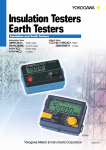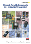
1
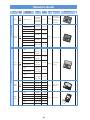
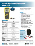
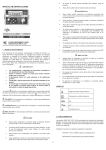
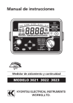
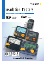
Insulation Testers
Battery Powered Insulation Testers
Analog Models
Digital Models
Single range
2 and 3 ranges
Single range
Single and 2 ranges
4 ranges
3213A
(110쎹180쎹60mm)
2406E
(120쎹110쎹60mm)
MY10
(125쎹103쎹53mm)
2406D
(120쎹110쎹60mm)
MY40
(125쎹103쎹53mm)
ISO9001
ISO14001
Bulletin MY-E
Selection Guide
Type
4
ranges
Series/
Model
Suffix Code
& Backlight
MY40
01 (EL-illuminated)
Digital insulation testers
51 (N/A)
61 (LED-illuminated)
Rating
AC Test
Display Additional Function
Voltage Range
External View
Page
Automatic discharge
125V/200MΩ
250V/200MΩ
500V/2000MΩ
1000V/2000MΩ
0–600V
125V/200MΩ
250V/200MΩ
0–300V
125V/200MΩ
0–300V
250V/200MΩ
0–300V
3 1/2-digit
LCD
Conductor resistance
measurement
P.3
Comparator function
Memory function
52 (N/A)
62 (LED-illuminated)
53 (N/A)
Single & 2
ranges
2406D
63 (LED-illuminated)
3 1/2-digit
LCD
54 (N/A)
500V/200MΩ
0–600V
1000V/2000MΩ
0–600V
Automatic discharge
P.4
64 (LED-illuminated)
55 (N/A)
65 (LED-illuminated)
31 (N/A)
25V/5MΩ
50V/10MΩ
41 (EL-illuminated)
0–300V
125V/20MΩ
32 (N/A)
125V/20MΩ
42 (EL-illuminated)
250V/50MΩ
0–300V
33 (N/A)
2&3
ranges
125V/20MΩ
250V/50MΩ
2406E
43 (EL-illuminated)
34 (N/A)
Analog
500V/100MΩ
Analog insulation testers
35 (N/A)
Single
range
Single
range
Battery check
P.5
0–600V
1000V/2000MΩ
250V/500MΩ
500V/1000MΩ
45 (EL-illuminated)
Automatic discharge
250V/50MΩ
500V/100MΩ
44 (EL-illuminated)
0–600V
0–600V
1000V/2000MΩ
01 (afterglow-illuminated) 125V/20MΩ
0–250V
02 (afterglow-illuminated) 250V/50MΩ
0–300V
03 (afterglow-illuminated) 500V/100MΩ
0–500V
04 (afterglow-illuminated) 500V/1000MΩ
0–500V
05 (afterglow-illuminated) 1000V/2000MΩ
0–500V
MY10
41 (N/A)
100V/20MΩ
0–150V
42 (N/A)
250V/50MΩ
0–250V
43 (N/A)
500V/100MΩ
0–300V
44 (N/A)
500V/1000MΩ
0–300V
45 (N/A)
1000V/2000MΩ
0–300V
46 (N/A)
125V/20MΩ
0–250V
3213A
Analog
Analog
2
Automatic discharge
Battery check
Battery check
P.6
P.7
MY40 Digital Insulation Tester
SERIES
쎲 Digital model with 4 voltage/resistance ratings
쎲 Multifunction
Insulation resistance, AC voltage and conductor resistance measurement
Insulation test mode: Comparator, memory, auto-hold and
discharge functions
All test modes:
Live-line alarm (excluding AC voltage
measurement), battery check and automatic power-off
쎲 Easy-to-view, fluctuation-free display
쎲 Double-action safety mechanism
Protection
against
inadvertent setting of
rotary switch to 1000 V
Testing Performance Specifications
Model
Rating
125V/200MΩ
250V/200MΩ
MY40
-01
500V/2000MΩ
1000V/2000MΩ
Range
Option
.4000
4.000
40.00
200.0
.4000
4.000
40.00
200.0
4.000
40.00
400.0
2000
4.000
40.00
400.0
2000
Resolution Measuring Range
.1kΩ
1kΩ
10kΩ
100kΩ
.1kΩ
1kΩ
10kΩ
100kΩ
1kΩ
10kΩ
100kΩ
1MΩ
1kΩ
10kΩ
100kΩ
1MΩ
Tolerance
Lower Limit of Rated Central Scale
measured Ω Current Value
0.125MΩ
1mA 5MΩ
0–.0199MΩ
.0200–20.00MΩ *
20.01–200.0MΩ
± (5%of rdg+6dgt)
± (2%of rdg+6dgt)
± 5%of rdg
0–.0499MΩ
.0500–20.00MΩ *
20.01–200.0MΩ
± (5%of rdg+6dgt)
± (2%of rdg+6dgt)
± 5%of rdg
0.25MΩ
0–0.999MΩ
1.000–500MΩ *
501–2000MΩ
± (5%of rdg+6dgt)
± (2%of rdg+6dgt)
± 5%of rdg
0.5MΩ
± (5%of rdg+6dgt)
± (2%of rdg+6dgt)
± 5%of rdg
2MΩ
0–1.999MΩ
2.000–1000MΩ *
1001–2000MΩ
Standard test conditions
Ambient temperature/humidity ranges: 23 ±5:/45-75% RH
Tolerances under the above-mentioned conditions:
Deviation from zero scale value: 6 digits maximum
Indication of ∞ mark on bar graph: Approx. 4000 MΩ min. (500 V/1000 V)
Approx. 400 MΩ min. (125 V/250 V)
No-load voltage: 130% max. of rated voltage
1mA
5MΩ
1mA 50MΩ
Rated measuring current: 1 mA (0 to 20%) when in first effective measuring range
Short-circuit Current: 2 mA max.
AC voltage measurement (45-400 Hz)
Model
Range Resolution
MY40-01 600V
0.5mA 50MΩ
1V
Accuracy
Input Impedance
±(2% of rdg + 6dgt)
Approx. 2 MΩ
Conductor resistance measurement
Model
Range Resolution
MY40-01 400Ω
Accuracy
±(2% of rdg + 8dgt)
0.1Ω
Open-circuit Voltage
Buzzer sound
resistance: <40Ω.
* First effective measuring range; ** The minimum value at which the rated voltage can be maintained
General Specifications
Standard Accessories
Display: 3 1/2-digit LCD; 4000 count; backlight-illuminated; logarithmic
bar graph; extension bar graph–no fluctuations, as the display shows
the digits of a reading in the order in which each digit settles.
Example of Extension Bar Indicator View
The data value is
changing.
Product
Part Number
Qty
Protection cover
93013
1
Shoulder strap
99005
1
Line probe
98001
1
Earth probe
98002
1
User's manual
–
1
Batteries
–
4
The data value is fixed.
External Dimensions
Unit: mm
52.5
125
103
Comparator function:The MY40 alerts you by turning on the LOW
symbol and sounding the buzzer if the measured value is smaller than
the reference value. You can allocate as many as three user-defined
reference values to each rating. The factory-set defaults are 0.1 MΩ,
0.2 MΩ and 0.4 MΩ.
Memory function:For each rating, you can save as many as 20
INSULATION
TESTER
LIGHT
Enter
2000M½
MEM
MEAS
measurements at desired memory address numbers.
200M½
PULL LOCK
ALARM
1000V
500V
250V
125V
V
600V MAX
COMP
Select
OFF
Clr
1000V RELEASE
Automatic discharge function:The MY40 automatically begins
discharge when you turn off the MEAS switch. You can monitor the
state of discharge by checking the bar graph and make sure discharge
High-voltage indicators: The high-voltage symbol and LED lamp
come on to alert you when the MY40 is in insulation testing mode or if
any voltage remains to be discharged.
Live-line alarm:If you apply an AC voltage of approximately 40 V or
higher across the input terminals, the MY40 alerts you by blinking the
LED lamp and sounding the buzzer.
Overrange input alarm: If the voltage being measured exceeds 600 V
during AC voltage measurement, the MY40 alerts you by flashing the
Maximum Value indicator and sounding the buzzer.
93013
Protection cover
Auto-hold function: The tester retains the measured resistance for
approximately 5 seconds after the MEAS switch is turned off.
Dimensions: 125 (W) ҂ 103 (H) ҂ 53 (D) (mm), excluding protrusions
Weight: 420 g (main unit and batteries only, excluding accessories)
Batteries: Four AA (R6P) batteries
Note: See the list of accessories on the backside of this bulletin for more information on
accessories.
3
B9108XA
Accessory-housing case
93015
Carrying case
(case for housing both the main
unit and accessories)
2406D Series of Digital Insulation Testers
SERIES
2406 51 2406 52 2406 53 2406 54 2406 55 2406 61
2406 62 2406 63 2406 64 2406 65
쎲 Digital models with single and two ratings
쎲 AC voltage measurement
쎲 Automatic discharge
쎲 EL backlight
쎲 Addition of 500 V/2000 MΩ model
쎲 Excellent tolerance: 2% of reading + 1 digit
(first effective measuring range)
Testing Performance Specifications
Range
Lower Limit of Rated Central Scale
Tolerance
Option Resolution Measuring Range
Value
measured Ω Current
.4000
.1kΩ
2406 51 125V/
0–.0199MΩ
±(5% of rdg + 6dgt) 0.125MΩ
1mA
5MΩ
4.000
1kΩ .0200–10.00MΩ* ±(2% of rdg + 1dgt)
2406 61 200MΩ
40.00
10kΩ 10.01–200.0MΩ
±5% of rdg
200.0 100kΩ
.4000
.1kΩ
0–.0499MΩ
±(5% of rdg + 6dgt)
250V/
1mA
5MΩ
0.25MΩ
4.000
1kΩ .0500–20.00MΩ* ±(2% of rdg + 1dgt)
200MΩ
40.00
10kΩ 20.01–200.0MΩ
±5% of rdg
200.0 100kΩ
.4000
.1kΩ
2406 52 125V/
0–.0199MΩ
±(5% of rdg + 6dgt) 0.125MΩ
1mA
5MΩ
4.000
1kΩ .0200–10.00MΩ* ±(2% of rdg + 1dgt)
2406 62 200MΩ
40.00
10kΩ 10.01–200.0MΩ
±5% of rdg
200.0 100kΩ
.4000
.1kΩ
2406 53 250V/
0–.0499MΩ
±(5% of rdg + 6dgt)
1mA
5MΩ
0.25MΩ
4.000
1kΩ .0500–20.00MΩ* ±(2% of rdg + 1dgt)
2406 63 200MΩ
40.00
10kΩ 20.01–200.0MΩ
±5% of rdg
200.0 100kΩ
.4000
.1kΩ
2406 54 500V/
0–.0999MΩ
±(5% of rdg + 6dgt)
1mA
5MΩ
0.5MΩ
4.000
1kΩ
2406 64 200MΩ
.1000–50.0MΩ* ±(2% of rdg + 1dgt)
40.00
10kΩ
50.1–200.0MΩ
±5% of rdg
200.0 100kΩ
4.000
1kΩ
2406 55 1000V/
0–1.999MΩ
±(5% of rdg + 6dgt)
1MΩ 1mA*** 50MΩ
10kΩ 2.000–1000MΩ* ±(2% of rdg + 1dgt)
2406 65 2000MΩ 40.00
400.0 100kΩ
1001–2000MΩ
±5% of rdg
2000
1MΩ
* First effective measuring range; ** The minimum value at which the rated voltage can be maintained;
Non-backlit
LED-backlit
*** 0.55 mA in the case of the lower limit of the first effective measuring range
Model
Rating
General Specifications
Standard test conditions:
Ambient temperature/humidity ranges: 23 ±5:/45-75% RH
Position of use: Unrestricted
Effect of geomagnetism: None
Low-battery alarm: The battery symbol on the LCD comes on for a
battery voltage level of 7 V ±0.5 V or lower.
No-load voltage: 130% max. of rated voltage
Rated measuring current: 1 mA (0 to 20%) when in first effective
measuring range
Short-circuit current: 12 mA max.
AC voltage measurement specifications
Model
Range Resolution
Accuracy
Input Impedance
2406 51, 52, 53
300V
2406 61, 62, 63
1V
±(1.5% of rdg + 6dgt) Approx. 1.5 MΩ
2406 54, 55
2406 64, 65
1V
±(1.5% of rdg + 6dgt) Approx. 1.5 MΩ
600V
Large switch for better operation
External Dimensions
Discharge function: The tester automatically discharge when you turn
off the MEAS switch. The segment bar extends if there is any residual
voltage in the circuit under test. You can make sure discharge is
complete by checking that the segment bar disappears from the display.
Under this condition, the tester is ready to enter voltage measurement
mode.
Unit: mm
120
53
110
AC voltage measurement: The tester enters AC voltage
measurement mode when you turn on the power (rotary) switch.
Auto-hold function:
The tester retains the measured resistance for approximately 5
seconds after the MEAS switch is turned off.
6
Display: 3 1/2-digit LCD; 4000 count maximum; 42-segment, logarithmic bar
graph; overrange input indicator—the OL symbol comes on if the measured
value exceeds 2000 count (200.0 range).
MΩ range selection:
Fully automatic ranging
Range step-up:
The tester shifts the range one step upward for input levels higher than
4000 count.
Range step-down:
The tester shifts the range one step downward for input levels lower
than 360 count.
B9108XA
Accessory-housing case
Dimensions (main unit): Approx. 120 (W) ҂ 110 (H) ҂ 60 (D) (mm)
Weight: Approx. 500 g (including batteries)
Batteries: Six AA (R6P) batteries
Standard Accessories
Note: See the list of accessories on the backside of this bulletin for information on
accessories.
Same as those of the 2406E series.
4
B9705MU
Hard case
7
2406E Series of Analog Insulation Testers
SERIES
2406 31 2406 32 2406 33 2406 34 2406 35 2406 41
2406 42 2406 43 2406 44 2406 45
쎲 Analog models with two and three ratings
쎲 AC voltage measurement
쎲 Automatic discharge
쎲 Sky blue EL backlight
쎲 Increased safety (covered battery charger)
Testing Performance Specifications
Model
Rating
2406 31
2406 41
25V/5MΩ
50V/10MΩ
125V/20MΩ
125V/20MΩ
250V/50MΩ
125V/20MΩ
250V/50MΩ
500V/100MΩ
250V/50MΩ
500V/100MΩ
1000V/2000MΩ
250V/500MΩ
500V/1000MΩ
1000V/2000MΩ
2406 32
2406 42
2406 33
2406 43
2406 34
2406 44
2406 35
2406 45
EL-backlit
Effective
Central
AC Voltage Lower limit of
Rated Current
Measuring range Scale Value Measuring range measured Ω
0.001–5MΩ
0.1MΩ
0–300V
1mA
0.025MΩ
0.005–10MΩ
0.2MΩ
1mA
0.05MΩ
0.01–20MΩ
0.5MΩ
1mA
0.125MΩ
0.01–20MΩ
0.5MΩ
0–300V
1mA
0.125MΩ
0.01–50MΩ
1MΩ
1mA
0.25MΩ
0.01–20MΩ
0.5MΩ
0–600V
1mA
0.125MΩ
0.01–50MΩ
1MΩ
1mA
0.25MΩ
0.05–100MΩ
2MΩ
1mA
0.5MΩ
0.01–50MΩ
1MΩ
0–600V
1mA
0.25MΩ
0.05–100MΩ
2MΩ
1mA
0.5MΩ
1–2000MΩ
50MΩ
1mA**
1MΩ
0.1–500MΩ
10MΩ
0–600V
1mA**
0.25MΩ
0.5–1000MΩ
20MΩ
1mA**
0.5MΩ
1–2000MΩ
50MΩ
1mA**
1MΩ
* The minimum value at which the rated voltage can be maintained;
** 0.55 mA in the case of the first effective measuring range
Non-backlit
General Specifications
Standard test conditions:
Ambient temperature/humidity ranges: 23 ±5 /45-75% RH
Position of use: Horizontal (5° max. of angle of inclination)
External magnetic fields: None
Battery voltage: Within effective voltage range
(The pointer must stay within the range indicated by the BAT symbol
when the battery check is performed.)
Tolerances under the above-mentioned conditions:
Resistance measurement: First effective measuring range = ±5% of reading
Second effective measuring range = ±10% of reading
Infinite and zero scale values: 0.7% max. of scale length
AC voltage: ±10% of maximum scale value
No-load voltage: 130% max. of rated voltage
Rated measuring current: 1 mA (0 to 20%) when in first effective measuring range
Short-circuit current: 12 mA max.
External Dimensions
Scale length: Approx. 86 mm (outer scale)
Unit: mm
120
53
Discharge function: The tester automatically begins discharge when you turn off the
MEAS switch. The pointer swings if there is any residual voltage in the circuit under test.
You can make sure discharge is complete by checking that the pointer swings back to
the infinite (∞) scale value. Under this condition, the tester is ready to enter voltage
measurement mode.
110
AC voltage measurement: AC voltage measurement is possible wherever the rotary
switch is positioned.
Dimensions (main unit): Approx. 120 (W) ҂ 110 (H) ҂ 60 (D) (mm)
Weight: Approx. 500 g (including batteries)
Batteries: Six AA (R6P) batteries
Accessories: See the list of accessories on the backside of this bulletin for information
on accessories.
B9108XA
Accessory-housing case
Standard Accessories
Product
Part Number
Qty
Remarks
98007
1
Earth probe(blake);approx. 1mlong
Line probe(vermilion);approx. 1m long
Carrying case
B9075MU
1
w/probe-housing
pocket and neck strap
User's manual
–
1
–
Batteries
–
6
–
Earth and Line probes
5
B9705MU
Hard case
7
MY10 Series of Analog Insulation Testers
SERIES
Analog models with single rating
MY10-01:125V/20MΩ
MY10-02:250V/50MΩ
MY10-03:500V/100MΩ
MY10-04:500V/1000MΩ
MY10-05:1000V/2000MΩ
AC voltage measurement
Automatic discharge
A wide choice of accessories
–Designed for shared use with the MY40
Testing Performance Specifications
Model
Rating
Effective Measuring Range
MY10-01
MY10-02
MY10-03
MY10-04
MY10-05
125V/20MΩ
250V/50MΩ
500V/100MΩ
500V/1000MΩ
1000V/2000MΩ
0.01–20MΩ
0.01–50MΩ
0.05–100MΩ
0.5–1000MΩ
1–2000MΩ
Central Scale
Value
0.5MΩ
1MΩ
2MΩ
20MΩ
50MΩ
Standard test conditions:
Ambient temperature/humidity ranges: 23 ±5 /45-75% RH
Position of use: Horizontal (5° max. of angle of inclination)
Effect of geomagnetism: None
Battery voltage: Within effective voltage range
(The pointer must stay within the range indicated by the BAT symbol when the battery check is performed.)
AC Voltage
Lower Limit of
Rated Current
Measuring Range
Measured Ω*
0–250V
1–1.2mA
0.125MΩ
0–300V
1–1.2mA
0.25MΩ
0–500V
1–1.2mA
0.5MΩ
0–500V
0.5–0.6mA
1MΩ
0–500V
0.5–0.6mA
2MΩ
* The minimum value at which the rated voltage can be maintained
Tolerances under the above-mentioned conditions:
Resistance measurement: First effective measuring range = ±5% of reading
Second effective measuring range = ±10% of reading
Infinite and zero scale values: 0.7% max. of scale length
AC voltage: ±10% of maximum scale value
No-load voltage: 130% max. of rated voltage
Rated measuring current: 1 mA (0 to 20%) when in first effective measuring range
Short-circuit current: 12 mA max.
General Specifications
External Dimensions
Unit: mm
Overall scale length: Approx. 107 mm; afterglow-illuminated scale plate
52.5
125
AC voltage measurement: If any AC voltage is present across the
test terminals, the tester lets you know by pointing to an AC voltage
value and turning on the LED lamp. You can perform AC voltage
measurement with the MEAS switch turned off.
103
Additional functions:
• Automatic discharge function
- If the object under test remains electrified after the MEAS switch is
turned off, the tester lets you know by turning on the LED lamp. If you
leave the tester connected to the electrified object, the tester
automatically begins to discharge electricity and then finishes
discharging—the LED lamp comes on and then goes out.
- When the object under test is capacitive and electrified, the tester lets
you know by turning on the LED lamp. When left connected to the
object, the tester automatically discharges electricity, thus preventing
possible electric shock or spike noise at power-on.
• Battery check (BAT mark on the scale plate)
Battery life: Approx. 10 hours when continuously operated on manganese-oxide batteries with the pointer pointing to the central scale value.
93013
Protection cover
Batteries: Four AA (R6P) batteries
Dimensions: Approx. 125 (W) ҂ 103 (H) ҂ 53 (D) (mm), excluding
protrusions
93015
Carrying case
(case for housing both the main
unit and accessories)
Weight: Approx. 500 g (main unit and batteries only, excluding accessories)
Compliance: EN61010-1:1993; EN61010-2-31:1995
(Overvoltage Category III, Pollution Degree 2 installations for indoor use)
B9108XA
Accessory-housing case
Standard Accessories
Part Number
Qty
Protection cover
Product
93013
1
Shoulder strap
99005
1
Line probe
98001
1
Earth probe
98002
1
User's manual
–
1
Batteries
–
4
6
NOTICE
World Wide Web site at
http://www.yokogawa.com/MCC
YOKOGAWA M & C CORPORATION
International Sales Dept.
Musashino Center Bldg.
1-19-18 Nakacho, Musashino-shi, Tokyo, 180-0006 Japan
Phone: +81-422-55-8755 Facsimile: +81-422-55-8954
YOKOGAWA CORPORATION OF AMERICA (U.S.A.)
YOKOGAWA EUROPE B. V. (THE NETHERLANDS)
YOKOGAWA ENGINEERING ASIA PTE. LTD. (SINGAPORE)
YOKOGAWA AMERICA DO SUL LTDA (BRAZIL)
YOKOGAWA MEASURING INSTRUMENTS KOREA CORPORATION (KOREA)
YOKOGAWA AUSTRALIA PTY. LTD. (AUSTRALIA)
YOKOGAWA BLUE STAR LTD. (INDIA)
YOKOGAWA MIDDLE EAST E.C. (BAHRAIN)
LTD. YOKOGAWA ELECTRIC (RUSSIAN FEDERATION)
Phone: +1-770-253-7000
Phone: +31-334-64-1611
Phone: +65-241-9933
Phone: +55-11-5681-2400
Phone: +82-2-551-0660 to 0664
Phone: +61-2-9805-0699
Phone: +91-80-227-1513
Phone: +973-358100
Phone: +7-095-737-7868
Subject to change without notice.
All Rights Reserved. Copyright © 2000, Yokogawa M&C Corporation.
Facsimile: +1-770-251-2088
Facsimile: +31-334-64-1610
Facsimile: +65-241-2606
Facsimile: +55-11-5681-1274/4434
Facsimile: +82-2-551-0665
Facsimile: +61-2-9888-1844
Facsimile: +91-80-227-4270
Facsimile: +973-336100
Facsimile: +7-095-737-7869
[Ed: 02/b]
● Before using the product, read the instruction manual
carefully to ensure proper and safe operation.
Represented by:
MCK-ES9
Printed in Japan: Apr 2002(C)/5,000(YG)