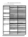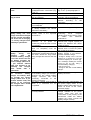
1
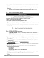
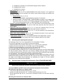
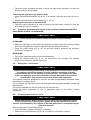
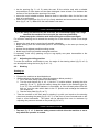
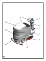
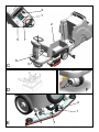
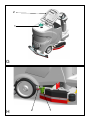
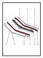
CT110 RIDE-ON SCRUBBER
DRYER
OPERATOR MANUAL
Clemas & Co. Unit 5 Ashchurch Business Centre, Alexandra Way, Tewkesbury,
Gloucestershire, GL20 8NB.
Tel: 01684 850777
Fax: 01684 850707
Email: [email protected]
Web: www.clemas.co.uk
ENGLISH
(Translation of original instructions)
1.
CONTENTS
1.
CONTENTS .......................................................................................................................... 2
2.
GENERAL INFORMATION .................................................................................................. 4
2.1.
2.2.
2.3.
3.
SCOPE OF THE MANUAL ................................................................................................................... 4
IDENTIFYING THE MACHINE ............................................................................................................. 5
DOCUMENTATION PROVIDED WITH THE MACHINE ........................................................................... 5
TECHNICAL INFORMATION............................................................................................... 5
3.1.
3.2.
3.3.
4.
GENERAL DESCRIPTION ................................................................................................................... 5
LEGEND .......................................................................................................................................... 5
DANGER ZONES ............................................................................................................................... 5
SAFETY INFORMATION ..................................................................................................... 6
4.1.
5.
SAFETY REGULATIONS .................................................................................................................... 6
HANDLING AND INSTALLATION ....................................................................................... 9
5.1.
LIFTING AND TRANSPORTING THE PACKAGED MACHINE .................................................................. 9
5.2.
CHECKS ON DELIVERY..................................................................................................................... 9
5.3.
UNPACKING .................................................................................................................................... 9
5.4.
BATTERIES .................................................................................................................................... 10
5.4.1. Batteries: preparation .............................................................................................................. 10
5.4.2. Batteries: installation and connection ...................................................................................... 10
5.4.3. Batteries: removal.................................................................................................................... 11
5.5.
THE BATTERY CHARGER ............................................................................................................... 11
5.5.1. Choosing the battery charger ................................................................................................... 11
5.5.2. Preparing the battery charger................................................................................................... 11
5.6.
LIFTING AND TRANSPORTING THE MACHINE .................................................................................. 12
6.
PRACTICAL GUIDE FOR THE OPERATOR..................................................................... 12
6.1.
CONTROLS - DESCRIPTION ............................................................................................................ 12
•
DISK RELEASE BUTTON (FIG. A, REF. 16): MICRO SCRUB / ECS MACHINE, ENABLES AUTOMATIC
RELEASE OF THE MICROFIBRE DISK, BRUSH OR ABRASIVE DISK FROM THE HEAD. ........................................ 13
6.2.
MOUNTING AND ADJUSTING THE SQUEEGEE .................................................................................. 13
6.3.
MOUNTING AND CHANGING THE BRUSH/ABRASIVE DISKS (STANDARD MACHINE). ................ 13
6.4.
AUTOMATIC ATTACHMENT AND RELEASE OF THE MICROFIBRE DISK/BRUSHES/ABRASIVE DISKS
(MICRO SCRUB / ECS MACHINE) ......................................................................................................... 14
ATTACHING:............................................................................................................................................ 14
RELEASING:............................................................................................................................................. 14
6.5.
DETERGENTS - INSTRUCTIONS....................................................................................................... 14
6.6.
PREPARING THE MACHINE FOR WORK............................................................................................ 14
6.7.
ADJUSTING THE RIDING POSITION .................................................................................................. 15
6.8.
WORKING...................................................................................................................................... 15
7.
PERIODS OF INACTIVITY................................................................................................. 18
8.
BATTERY MAINTENANCE AND CHARGING .................................................................. 18
8.1.
8.2.
9.
PROCEDURE FOR CHARGING USING THE BATTERY CHARGER INSTALLED BY THE MANUFACTURER 18
PROCEDURE FOR CHARGING USING AN EXTERNAL BATTERY CHARGER ......................................... 19
MAINTENANCE INSTRUCTIONS ..................................................................................... 19
9.1.
MAINTENANCE - GENERAL RULES ................................................................................................. 19
9.2.
ROUTINE MAINTENANCE ............................................................................................................... 19
9.2.1
Suction motor air filter and float: cleaning .............................................................................. 19
9.2.2
Detergent solution filter: cleaning ........................................................................................... 19
9.2.3
Squeegee blades: replacing...................................................................................................... 20
9.2.4
Fuses: replacing ....................................................................................................................... 20
9.3.
REGULAR MAINTENANCE .............................................................................................................. 20
9.3.1. Daily operations ...................................................................................................................... 20
2
ENGLISH
9.3.2.
9.3.3.
Weekly operations ................................................................................................................... 20
Six monthly operations ............................................................................................................ 21
10.
TROUBLESHOOTING AND ERROR CODES .............................................................. 22
10.1.
10.2.
10.3.
HOW TO RESOLVE POSSIBLE PROBLEMS ........................................................................................ 22
ALARMS DISPLAYED...................................................................................................................... 25
MOTOR DRIVE ALARM BOARD ....................................................................................................... 26
ENGLISH
3
2.
GENERAL INFORMATION
Read this manual carefully before carrying out any work on the machine1.
2.1.
Scope of the manual
This manual has been written by the Manufacturer and is an integral part of the machine.
It defines the purpose for which the machine has been designed and constructed and
contains all the information required by operators.
In addition to this manual containing all user information, other publications are available
providing specific information for maintenance personnel.
Constant respect for the instructions guarantees the safety of the operator and the
machine, low running costs and high quality results and extends the working life of the
machine. Failure to respect the instructions may lead to damage to the operator,
machine, floor being washed and environment.
To find the topic that interests you more rapidly, consult the list of contents at the
beginning of the manual.
Parts of the text requiring special attention are highlighted in bold and preceded by the
symbols illustrated and described here.
! DANGER
Indicates the need for attention in order to avoid a series of consequences which
could cause death or damage to the health of the operator.
IMPORTANT
Indicates the need for attention in order to avoid a series of consequences which
could cause damage to the machine or work environment or financial loss.
i INFORMATION
Particularly important instructions.
In line with the company's policy of constant product development and updating, the
Manufacturer reserves the right to make modifications without warning.
Although your machine may differ appreciably from the illustrations in this document,
safety and the information contained in this manual are guaranteed.
1 The definition “machine” replaces the trade name of the appliance to which this manual refers.
4
ENGLISH
2.2.
Identifying the machine
The rating plate under the seat (fig. B, ref. 8) provides the following information:
• model;
• power supply;
• total nominal power;
• serial number;
• year of fabrication;
• weight fully loaded;
• maximum slope;
• barcode with serial number;
• manufacturer's identification.
2.3.
Documentation provided with the machine
• user manual;
• guarantee certificate;
• EC certificate of conformity.
3.
3.1.
TECHNICAL INFORMATION
General description
This machine is a scrubber drier for sweeping, washing and drying flat, horizontal, smooth
or moderately rough, even and obstacle free floors in civil and industrial premises.
The scrubber drier spreads a solution of water and detergent in the correct concentration
on the floor and then scrubs it to remove the dirt. By carefully choosing the detergent and
brushes (or abrasive discs) from the wide range of accessories available, the machine
can be adapted to a wide range of combinations of types of floor and dirt.
A suction system incorporated in the machine dries the floor after washing by means of
the low pressure generated in the collection tank by the suction motor. The squeegee
connected to the tank collects the dirty water.
3.2.
Legend
The main parts of the machine are as follows (fig. B):
• detergent solution tank (fig. B, ref. 1): contains and transports the mixture of clean
water and cleaning product;
• collection tank (fig. B, ref. 2): collects the dirty water picked up from the floor after
washing;
• control panel (fig. B, ref. 3);
• head assembly (fig. B, ref. 4): the main element is the brushes, the abrasive disk or the
microfibre disk (fig. B, ref. 5) which distribute the detergent solution on the floor and
remove the dirt;
• squeegee assembly (fig. B, ref. 6): wipes and dries the floor by collecting the water.
• concentrated solution tanks (OPTIONAL) (fig. C, ref. 1)
• battery compartment (fig. C, ref. 2)
• battery charger (OPTIONAL) (fig. C, ref. 3)
3.3.
Danger zones
A -Tank assembly: when using certain detergents, danger of irritation for eyes, skin,
mucous membranes and respiratory tract and of asphyxia. Danger represented by the
dirt collected from the environment (germs and chemical substances). Danger of
crushing between the two tanks when the collection tank is replaced on the solution
tank.
B -Control panel: danger of short circuit.
ENGLISH
5
C -Bottom of washing head: danger due to brush rotation.
D -Rear wheels: danger of crushing between the wheel and chassis.
E -Battery compartment: danger of short circuit between the battery poles and presence
of hydrogen during charging.
4.
4.1.
SAFETY INFORMATION
Safety regulations
Read the "User manual" carefully before start-up and use, or before performing
maintenance or any other work on the machine.
IMPORTANT
Rigorously respect all instructions in the Manual (in particular those relating to
danger and important information) and on the safety plates fitted to the machine.
The Manufacturer declines all liability for damage to people or things resulting from
failure to observe the instructions.
The appliance must be used exclusively by persons trained in its use and/or who have
demonstrated their ability and have been expressly instructed to use the appliance.
The machine must not be used by minors.
The machine must not be used for purposes other than those for which it was expressly
designed. Scrupulously respect all safety standards and conditions applicable to the type
of building in which the machine is to be operated (eg: pharmaceutical companies,
hospitals, chemicals, etc).
Do not use the machine in places with inadequate lighting or explosive atmospheres, on
public roads, in the presence of dirt hazardous to health (dust, gas, etc) and in unsuitable
environments.
The machine is designed for use at temperatures of between +4°C and +35°C. When the
machine is not being used, the temperature range is +0°C and +50°C.
The machine is designed to work in a humidity of between 30% and 95%.
Never use or pick up flammable liquids or explosives (eg. petrol, fuel oil, etc), flammable
gases, dry dusts, acids and solvents (eg. paint solvents, acetone etc) even if diluted.
Never pick up flaming or incandescent objects.
Never use the machine on slopes or ramps of more than 16%. In the case of slight
slopes, do not use the machine transversally, always manoeuvre with care and do not
reverse. When transporting the machine on steeper ramps or slopes, take the utmost
care to avoid tipping up and/or uncontrolled acceleration. Move the machine on ramps
and/or steps only with the brush head and squeegee raised.
Never park the machine on a slope.
The machine must never be left unattended with the motors on. Before leaving it, turn the
motors off, make sure it cannot move accidentally and disconnect the electrical power
supply.
Always pay attention to other people, children in particular, present in the place where you
are working.
Never use the machine to transport people or things or to tow things. Do not tow the
machine.
Never rest objects of any weight on the machine for any reason.
Never obstruct ventilation and heat dispersion slits.
Never remove, modify or circumvent safety devices.
Numerous unpleasant experiences have shown that a wide range of personal objects
may cause serious accidents. Before beginning work, remove jewellery, watches, ties,
etc.
6
ENGLISH
The operator must always use personal protection devices - protective apron or overalls,
non-slip waterproof shoes, rubber gloves, protective goggles and ear protectors and mask
to protect the respiratory tract.
Keep the hands away from moving parts.
Never use detergents other than those specified. Follow the instructions on the relative
safety sheet. We recommend keeping detergents out of reach of children. In the event of
contact with the eyes, wash immediately with abundant water. If ingested, consult a
doctor immediately.
Make sure the power sockets used for the battery charger are connected to a suitable
earth system and protected by differential thermal solenoid switches.
Make sure the electrical characteristics of the machine (voltage, frequency, absorbed
power) given on the rating plate are the same as those of the mains electricity supply.
The earth wire is yellow and green. Never connect this wire to anything other than the
earth contact of the socket.
It is indispensable to respect the battery manufacturer's instructions and current
legislation. The batteries should always be kept clean and dry to avoid surface leakage
current. Protect the batteries from impurities such as metal dust.
Never rest tools on the batteries as this could cause short circuit and explosion.
When using battery acid, always follow the relative safety instructions scrupulously.
In the presence of particularly strong magnetic fields, assess the possible effect on the
control electronics.
Never wash the machine with water jets.
The fluids collected contain detergent, disinfectant, water and organic and inorganic
material. They must be disposed off in accordance with current legislation.
In the case of malfunction and/or faulty operation, turn the machine off immediately,
disconnect from the mains power supply or batteries and do not tamper. Contact a
service centre authorised by the Manufacturer.
All maintenance operations must be performed in an adequately lit place and only after
isolating the machine from the power supply by disconnecting the battery terminals.
All work on the electrical system and all maintenance and repair operations other than
those explicitly described in this manual must be performed by specialised personnel
expert in the sector only.
Only original accessories and spare parts supplied by the Manufacturer may be used in
order to guarantee safe problem-free operation of the machine. Never use parts removed
from other machines or from other kits.
This machine has been designed and constructed to provide ten years' service from the
fabrication date shown on the rating plate. After this time, whether the machine has been
used or not, it should be disposed of according to current legislation in the country in
which it is used:
- the machine must be disconnected from the power supply, emptied of liquids and
cleaned;
- the product is classified as WEEE type special waste and is covered by the
requisites of the new environmental protection regulations (2002/96/EC WEEE). It
must be disposed of separately from ordinary waste in compliance with current
legislation and standards.
Special waste. Do not dispose of with ordinary waste.
Alternatively the machine must be returned to the Manufacturer for a complete overhaul.
If you decide to stop using the machine, you are recommended to remove the batteries
and dispose of them at an authorised collection centre.
ENGLISH
7
You should also make sure that all parts of the appliance which could represent a hazard,
particularly to children, are made safe.
8
ENGLISH
5.
5.1.
HANDLING AND INSTALLATION
Lifting and transporting the packaged machine
IMPORTANT
During all lifting operations, make sure the packaged machine is firmly anchored to
avoid it tipping up or being accidentally dropped.
Always load/unload lorries in adequately lit areas.
The machine, packaged on a wooden pallet by the Manufacturer, must be loaded using
suitable equipment (see EC Directive 2006/42 and subsequent amendments and/or
additions) onto the transporting vehicle. At destination, it must be unloaded using similar
means.
The squeegees are packed in cardboard boxes without pallet.
A fork lift truck must always be used to lift the packaged body of the machine. Handle
with care to avoid knocking or overturning the machine.
5.2.
Checks on delivery
When the carrier delivers the machine, make sure the packaging and machine are both
whole and undamaged. If the machine is damaged, make the carrier is aware of the
damage and before accepting the goods, reserve the right (in writing) to request
compensation for the damage.
5.3.
Unpacking
IMPORTANT
When unpacking the machine, the operator must be provided with the necessary
personal protection devices (gloves, goggles, etc) to limit the risk of accident.
Unpack the machine as follows:
• cut and remove the plastic straps using scissors or nippers;
• remove the cardboard;
• depending on the model, remove the metal brackets or cut the plastic straps fixing the
machine chassis to the pallet;
• using a sloping ramp, push the machine backwards off the pallet;
• unpack the brushes and squeegees;
• clean the outside of the machine in respect of safety regulations;
• once the machine is clear of the packaging, the batteries can be installed.
The packaging may be kept as it can be reused to protect the machine if it is moved to
another site or to a repair workshop.
Otherwise it must be disposed off in compliance with current legislation.
ENGLISH
9
! DANGER
Failure to observe these instructions could cause possibly serious damage to people
and things and invalidates the guarantee.
5.4.
Batteries
Two different types of battery may be installed on these machines:
• wet batteries: the electrolyte level must be checked regularly. When necessary, top
up with distilled water until the plates are covered. Do not over fill (5 mm max. above
the plates).
• gel batteries: this type of battery requires no maintenance.
The technical characteristics must correspond to those indicated in the paragraph on the
technical specification of the machine. The use of heavier batteries could seriously
jeopardise manoeuvrability and lead to the brush motor overheating. Batteries with a
lower capacity and weight will require recharging more frequently.
They must be kept charged, dry and clean and the connections must be tight.
i INFORMATION
Follow
board.
1.
2.
3.
the instructions below to set the type of battery installed on the machine's logic
Switch off the machine by turning the main switch (fig. A, ref. 1) to the 0 position.
Press the emergency button (fig. A ref. 10) (red light on).
Hold the solution/concentrated detergent flow quantity variation buttons (fig. A, ref.
2) down and simultaneously press the emergency button (fig. A, ref. 10) (red light
off). Keep the solution/concentrated detergent flow quantity variation buttons
pressed (fig. A, ref. 2) until "tip A", "tip G" appears on the display.
4. Use the solution flow regulation button (fig. A, ref. 3) to select the type of batteries
installed: "tip A" wet batteries, "tip G" gel batteries.
5. Memorise the parameter by pressing the emergency button (fig. A ref. 10).
5.4.1. Batteries: preparation
! DANGER
During installation of the batteries or any type of battery maintenance, the operator
must be provided with the necessary personal protection devices (gloves, goggles
overalls, etc) to limit the risk of accident. Keep away from naked flames, avoid
short circuiting the battery poles, avoid sparks and do not smoke.
The batteries are normally supplied filled with acid and ready for use.
If the batteries are dry, before mounting them on the machine, proceed as follows:
• remove the caps and fill all elements with specific sulphuric acid solution until the
plates are entirely covered (this requires at least a couple of passes for each element);
• leave for 4-5 hours to allow the air bubbles to come to the surface and the plates to
absorb the electrolyte;
• make sure the level of electrolyte is still above the plates and if necessary top up with
sulphuric acid solution;
• close the caps;
• mount the batteries on the machine (following the procedure described below).
Before starting up the machine for the first time, charge the batteries as follows.
5.4.2. Batteries: installation and connection
! DANGER
Check that all switches on the control panel are in the "0" (off) position.
Make sure you connect the terminals marked with a "+" to the positive poles of the
battery. Do not check the battery charge by sparking.
10
ENGLISH
Meticulously follow the instructions given below as short circuiting the batteries
could cause them to explode.
1) Make sure the two tanks are empty (if necessary, empty them. See the relevant
paragraph).
2) Raise the solution tank and tilt it backwards ACCOMPANYING IT through about 90°.
This provides access to the battery compartment from above.
IMPORTANT
before lifting the solution tank, always remove the suction hose fitted to the squeegee.
3) Place the batteries in the battery compartment.
IMPORTANT
Mount the batteries on the machine using means suitable for their weight.
The positive and negative poles have different diameters.
6) Referring to the arrangement of cables shown in the diagram (fig. D), connect the
battery cable and bridge terminals to the battery poles.
Arrange the cables as shown in the diagram (fig. D), tighten the terminals on the poles
and cover with Vaseline.
7) Lower the tank into the working position
8) When using the machine, follow the instructions below.
5.4.3. Batteries: removal
! DANGER
When removing the batteries, the operator must be equipped with suitable personal
protection devices (gloves, goggles, overalls, safety shoes, etc) to reduce the risk
of accidents. Make sure the switches on the control panel are in the "0" position
(off) and the machine is turned off. Keep away from naked flames, do not short
circuit the battery poles, do not cause sparks and do not smoke. Proceed as
follows:
• disconnect the battery wiring and bridge terminals from the battery poles.
• if necessary, remove the devices fixing the battery to the base of the machine.
• lift the batteries from the compartment using suitable lifting equipment.
5.5.
The battery charger
IMPORTANT
Never allow the batteries to become excessively flat as this could damage them
irreparably.
5.5.1. Choosing the battery charger
Make sure the battery charge is compatible with the batteries to be charged:
− tubular lead batteries: an automatic charger is recommended
− Consult the battery charger manufacturer and manual to confirm the choice.
− gel batteries: use a charger specific for this type of battery.
5.5.2. Preparing the battery charger
If you wish to use a battery charger not provided with the machine, you must fit it with the
connector supplied with the machine.
To install the connector, proceed as follows:
ENGLISH
11
• remove about 13 mm of protective sheath from the red and black wires of the battery
charger;
• insert the wires into the connector contacts and squeeze them forcefully with suitable
pliers;
• respect the polarity (red wire + black wire -) when inserting the wires into the
connector.
• Insert the wired-up connector into the connector on the machine (fig. C, ref. 4).
5.6.
Lifting and transporting the machine
IMPORTANT
All phases must be performed in an adequately lit room and adopting the safety
measures most appropriate to the situation.
The operator must always use personal protection devices.
To load the machine onto a means of transport, proceed as follows:
• empty the collection and solution tanks;
• remove the squeegee and brushes (or abrasive disks);
• remove the batteries;
• place the machine on the pallet and fix it with plastic straps or metal brackets;
• lift the pallet (with the machine) using a fork lift truck and load it onto the means of
transport;
• anchor the machine to the means of transport with cables connected to the pallet and
machine itself.
6.
6.1.
PRACTICAL GUIDE FOR THE OPERATOR
Controls - Description
These terms have the following meanings:
STANDARD MACHINE, version of the machine designed for use with brushes or
abrasive disks.
MICRO SCRUB / ECS MACHINE, version of the machine designed for use with
microfibre disk, brushes or abrasive disks.
With reference to fig. A, the machine has the follow controls and indicator lights:
• Power light (fig. A, ref. 5): consists of 4 LEDs indicating the battery charge level (see
paragraph 6.7)
• Main Switch (fig. A, ref. 1): enables and disables the electrical power supply to all
machine functions.
• Emergency button (fig. A, ref. 10): acts as a safety device.
• Speed potentiometer (fig. A, ref. 13): regulates the speed of the machine forwards
and backwards
• Solution flow regulation button (fig. A, ref. 3): there are five operating modes
• STANDARD
• AUTOMATIC
• ECONOMY.
• MICROFIBRE (MICRO SCRUB / ECS MACHINE)
• CHEM-DOSE
• Solution/concentrated detergent flow quantity variation buttons (fig. A, ref. 2):
vary the flow of solution/concentrated detergent
• Display (fig. A, ref. 6):
12
ENGLISH
•
•
•
•
•
•
•
a) displays the quantity of concentrated detergent when enabled.
b) displays alarm codes.
c) displays hour counter.
Horn button (fig. A, ref. 12):
Suction button (fig. A, ref. 9): enables/disables the suction function. If you press this
button for more than five seconds, the suction motor starts working even without the
operator on board.
• Brush button (fig. A, ref. 8):
• STANDARD MACHINE, enables/disables operation of the head.
• MICRO SCRUB / ECS MACHINE, enables/disables operation of the head. Hold
the button down for at least 3 seconds to select the operating mode, "BRUSHPAD" with brushes/abrasive disk, or "MICROFIBRE" with microfibre disk.
Solution tank level indicator: (fig. A, ref. 14): when there is not enough water in the
solution tank, the LED comes on and the head and solenoid valve are turned off
(OPTIONAL)
Collection tank level indicator (fig. A, ref. 11): when the collection tank is full, the
LED comes on and after a few seconds the suction motor is turned off.
Head pressure variation buttons (fig. A, ref. 7): vary the pressure of the brushes on
the floor
Motor drive board indicator (fig. A, ref. 15): indicates the status of the motor drive
board (see section: “Motor drive alarm board”).
Disk release button (fig. A, ref. 16): MICRO SCRUB / ECS MACHINE, enables
automatic release of the microfibre disk, brush or abrasive disk from the head.
6.2.
Mounting and adjusting the squeegee
The squeegee (fig. B, ref. 6) is responsible for the first phase of drying.
To mount the squeegee on the machine, proceed as follows:
1) insert the sleeve of the suction hose (fig. E, ref. 1) fully into the squeegee;
2) slacken the two knobs (fig. E, ref. 2) at the centre of the squeegee;
3) insert the two threaded pins into the slots on the support (fig. E, ref. 3)
4) fix the squeegee by tightening the two knobs (fig. E, ref. 2)
The squeegee blades scrape the film of water and detergent from the floor and prepare
the way for perfect drying. With time, the constant rubbing makes the edge of the blade
in contact with the floor rounded and cracked, reducing the drying efficiency and requiring
it to be replaced. The state of wear should be checked frequently.
For perfect drying, the squeegee must be adjusted in such a way that the edge of the rear
blade bends during operation by about 45° with resp ect to the floor at every point. Adjust
the angle of the blade during operation by regulating the height of the two wheels
positioned in front of/behind the squeegee.
6.3.
Mounting and changing the brush/abrasive disks (STANDARD MACHINE).
IMPORTANT
Never work without the brushes and abrasive disks perfectly installed.
The terms RIGHT and LEFT refer to the forward movement of the machine
Mounting the right brush (or abrasive disk)
• remove the right and left side hatches (fig. L, ref. 2);
• position the right brush (fig. M, ref. 1) under the drive disk (fig. M, ref. 2)
• lift the right brush (fig. M, ref. 1) and turn it clockwise to block it on the drive disk (fig.
M, ref. 3)
Mounting the left brush (or abrasive disk)
ENGLISH
13
• Follow the same procedure as used to mount the right brush, blocking it on the drive
disk by turning it anticlockwise.
Removing the right brush (or abrasive disk)
• rotate the brush anticlockwise (fig. M, ref. 1) to release it from the drive disk (fig. M, ref.
3)
• Replace the right and left side hatches (fig. L, ref. 2);
Removing the left brush (or abrasive disk)
• Follow the same procedure as used to remove the right brush, releasing it from the
drive disk by turning it clockwise.
6.4.
Automatic attachment and release of the microfibre disk/brushes/abrasive
disks (MICRO SCRUB / ECS MACHINE)
IMPORTANT
Never operate the machine without the disks correctly installed.
ATTACHING:
• Raise the side flaps on both sides and position the disks under the housing, making
sure they rest against the stops to align them with the attachment device.
• Press the brush button (fig. A, ref. 8) and the machine performs the automatic
attachment manoeuvre
RELEASING:
• Turn off the head and suction motors and all devices.
• Press the release button (fig. A, ref. 16) and hold for five seconds. The machine
performs the automatic release manoeuvre.
6.5.
Detergents - Instructions
IMPORTANT
Always dilute the detergent according to the manufacturer's instructions. Do not
use sodium hypochlorite (bleach) or other oxidants, particularly in strong
concentrations. Do not use solvents or hydrocarbons. The temperature of the
water and detergent must not exceed the maximum indicated in the technical
specification. They must be free of sand and/or other impurities.
The machine has been designed for use with low-foam biodegradable detergents made
specifically for scrubber driers.
For a complete and up-to-date list of the detergents and chemicals available, contact the
Manufacturer.
Use products suitable for the floor and dirt to be removed only.
Follow the safety regulations on use of detergents given in the section "Safety
regulations".
6.6.
Preparing the machine for work
IMPORTANT
Before starting work, wear overalls, ear protectors, non-slip waterproof shoes,
mask to protect the respiratory tract, gloves and all other personal protection
devices recommended by the supplier of the detergent used or necessitated by the
work environment.
Before starting work, proceed as follows:
• check the battery charge (recharge if necessary);
• make sure the collection tank (fig. B, ref. 2) is empty. If necessary, empty it;
14
ENGLISH
• via the opening (fig. C, ref. 5) under the seat, fill the solution tank with a suitable
concentration of clean water and low-foam detergent. leave at least 5 cm between the
surface of the liquid and the opening of the tank;
• mount the most suitable brushes, abrasive disks or microfibre disks for the floor and
work to be performed.
• make sure the squeegee (fig. B, ref. 6) is firmly attached and connected to the suction
hose (fig. E, ref. 1). Make sure the back blade is not worn.
i INFORMATION
If you are using the machine for the first time, we recommend trying it on a large
obstacle-free surface first to acquire the necessary familiarity.
Always empty the collection tank before filling the solution tank again.
For effective cleaning and to extend the working life of the machine, follow a few simple
rules:
• prepare the work area by removing all possible obstacles;
• begin working from the furthermost point to avoid walking on the area you have just
cleaned;
• choose the straightest possible working routes;
• divide large floors into parallel rectangular sections.
If necessary, finish off by passing a mop or rag rapidly over parts inaccessible to the
scrubber drier.
6.7.
Adjusting the riding position
To make the machine comfortable to use, the angle of the steering wheel (fig. B, ref. 9)
can be adjusted using the lever (fig. B, ref. 11).
6.8.
Working
Starting up:
•
•
•
Prepare the machine as described above.
When starting up the machine, follow the sequence below precisely:
1. Sit on the seat (safety sensors are activated)
2. Turn the main switch (fig. A, ref. 1) into the "1" position without pressing the drive
pedal (fig. B, ref. 7), check the battery charge as shown by the indicator light (fig.
A, ref. 5). If the red LED flashes or is on steadily, or if the red and yellow LEDs are
both on, turn the main switch back to the "0" position and recharge the batteries
(see chapter 8).
3. Use the drive pedal (fig. B, ref. 7).
Take the machine to the work area by starting it up with your hands on the steering
wheel and pressing the pedal (fig. B, ref. 7) on the front to move forwards and on the
back to move backwards. The speed can be adjusted from zero to maximum by
adjusting the pressure exerted on the pedal (fig. B, ref. 7).
i INFORMATION
• The seat (fig. B, ref. 8) has two safety sensors which allow the machine to move
only when the operator is seated.
ENGLISH
15
i INFORMATION
The machine has a safety system to prevent it tipping over. This reduces the speed
on bends, irrespective of the pressure exerted on the drive pedal. This reduction of
speed on bends is therefore not a malfunction, but a feature which increases the
machine's stability in all conditions.
•
•
•
16
Press the brush button (fig. A, ref. 8). This command functions differently depending
on whether you are using the "STANDARD MACHINE" or the "MICRO SCRUB / ECS
MACHINE"):
STANDARD MACHINE, it enables machine operation (head and suction motors,
head actuator);
MICRO SCRUB / ECS MACHINE, it enables machine operation (head and suction
motors, head actuator) and if held down for at least five seconds, selects the
machine operating mode, BRUSH-PAD with brushes/abrasive disk or
MICROFIBRE with microfibre disk. The LED corresponding to the operating mode
selected (BRUSH-PAD, or MICROFIBRE) lights up.
Select the most suitable pressure for the head on the floor according to the type of
washing to be performed using the buttons (fig. A, ref. 7).
Select the most suitable flow according to the type of washing to be performed using
the button (fig. A, ref. 3). There are five options
1 STANDARD, the solution flow can be modified using the buttons (fig. A, ref. 2)
(STANDARD MACHINE ONLY)
2 AUTOMATIC, the solution flow is set by the machine according to the speed
(STANDARD MACHINE ONLY).
3 ECONOMY, the solution flow is fixed at the lowest level (STANDARD MACHINE
ONLY).
4 CHEM-DOSE STANDARD MACHINE, enables the solution tank pump
(OPTIONAL). To enter CHEM-DOSE mode, hold the button (fig. A, ref. 3) down
until the red LED corresponding to CHEM-DOSE comes on. To vary the quantity
of solution, you must first disable the programmes (STANDARD, AUTOMATIC,
ECONOMY) by pressing the button (fig. A, ref. 3). The quantity of solution can
now be adjusted using the buttons (fig. A, ref. 2) and the value set appears on the
display (fig. A, ref. 6). Once the quantity of solution has been set, the most
suitable type of solution flow must be selected (STANDARD, AUTOMATIC,
ECONOMY) using the button (fig. A, ref. 3). To disable the solution tank pump,
hold the button (fig. A, ref. 3) down for at least five seconds until the LED
corresponding to CHEM-DOSE goes out.
5 CHEM-DOSE MICRO SCRUB / ECS MACHINE enables the solution tank pump
(OPTIONAL). To enter CHEM-DOSE mode, hold the button (fig. A, ref. 3) down
until the red LED corresponding to CHEM-DOSE comes on. To vary the quantity
of solution, you must first disable the programmes (STANDARD, AUTOMATIC,
ECONOMY) by pressing the button (fig. A, ref. 3). The quantity of solution can
now be adjusted using the buttons (fig. A, ref. 2) and the value set appears on the
display (fig. A, ref. 6). Once the quantity of solution has been set, for BRUSH-PAD
mode only, the most suitable type of solution flow must be selected (STANDARD,
AUTOMATIC, ECONOMY) using the button (fig. A, ref. 3). When using CHEMDOSE in MICROFIBRE mode, you cannot use the STANDARD, AUTOMATIC and
ECONOMY programmes. To vary the flow, use the buttons (fig. A, ref. 2) only. To
disable the solution tank pump, hold the button (fig. A, ref. 3) down for at least five
seconds until the LED corresponding to CHEM-DOSE goes out.
6 MICROFIBRE, the solution flow can be varied using the buttons (fig. A, ref. 2)
(MICRO SCRUB / ECS MACHINE ONLY)
ENGLISH
•
•
Start cleaning, manoeuvring with the hands on the steering wheel (fig. B, ref. 9) and
moving the machine forwards or backwards by pressing the pedal (fig. B, ref. 7).
The working speed can be set using the maximum speed regulator (fig. A, ref. 13).
IMPORTANT
To avoid damaging the surface of the floor to be treated, avoid rotating the
brushes/pads/microfibre disks with the machine stationary.
Stopping:
•
•
•
•
Release the pedal (fig. B, ref. 7)
The machine does not have a parking brake as it is fitted with an electromagnetic
brake which automatically brakes the machine when the drive pedal is not pressed.
To stop all functions, press the brush button (fig. A, ref. 8).
Turn the main switch (fig. A, ref. 1) to the "0" position.
Running down of the batteries during work:
IMPORTANT
To avoid damaging the batteries and shortening their working life, do not continue
using the machine once the batteries are flat.
The meaning of the battery charge control light (fig. A, ref. 5) is given below:
1 flashing red LED: battery voltage under 18 V (ACID batteries) or under 19 V (GEL
batteries), drive is shut down. Recharge the batteries.
1 red LED on steadily: battery voltage between 18 and 20.5 V (ACID batteries) or 19
and 21.5 V (GEL batteries), SUPER-MINIMUM battery charge. Recharge the batteries.
1 red LED + 1 yellow LED on steadily: battery voltage between 20.5 and 21.5 V (ACID
batteries) or 21.5 and 22.5 V (GEL batteries), MINIMUM battery charge.
1 red LED + 1 yellow LED + 1 green LED_1 on steadily: battery voltage between 21.5
and 24 V (ACID batteries) or 22.5 and 25 V (GEL batteries), MEDIUM battery charge.
1 red LED + 1 yellow LED + 1 green LED_1 + 1 green LED_2 on steadily: battery
voltage between 24 and 27.4 V (ACID batteries) or 25 and 28.4 V (GEL batteries),
MAXIMUM battery charge.
IMPORTANT
Each time you fill the solution tank, always empty the collection tank.
! DANGER
Use suitable personal protection devices.
•
when the collection tank is full, the level indicator comes on (fig. A, ref. 11) and
after a few seconds the suction motor is turned off. You must stop working and
empty the tank.
Emptying the collection tank:
1
2
3
4
Stop the machine by releasing the pedal (fig. B, ref. 7)
Turn off all functions using the brush button (fig. A, ref. 8).
Take the machine to the disposal area.
Empty the collection tank through the hose (fig. B, ref. 10), then rinse the
tank with clean water.
ENGLISH
17
Emptying the solution tank:
5 Proceed as described in points 1 to 3.
6 At the end of work, empty the solution tank by by unscrewing the cap (fig.
E, ref. 4), then rinse the tank with clean water.
IMPORTANT
before lifting the solution tank, always remove the suction hose fitted to the squeegee.
IMPORTANT
When washing the collection tank, never remove the suction filter (fig. G, ref. 1)
from its housing and never direct the jet of water against the filter itself.
You are then ready to wash and dry again.
Pushing and pulling the machine:
When the drive cannot be used, to push or pull the machine easily, you must block the
electromagnetic brake by screwing up the screws (fig. F, ref. 1) .
After moving the machine, unscrew the screws to release the electromagnetic brake.
IMPORTANT
If the screws are not unscrewed, the electromagnetic brake remains inactive.
Never turn the machine on with the screws (fig. F, ref. 1) screwed up (brake
deactivated).
7.
PERIODS OF INACTIVITY
If the machine is not used for some time, remove the squeegee and brushes (or abrasive
disks), wash them and put them away in a dry place (preferably in a bag or wrapped in
plastic film) away from dust.
Make sure the tanks are completely empty and perfectly clean.
Completely recharge the batteries before storing them. During long periods of inactivity,
you should charge the batteries regularly (at least once every two months) to keep them
constantly at maximum charge.
IMPORTANT
If you do not charge the batteries regularly, they may be irrevocably damaged.
8.
BATTERY MAINTENANCE AND CHARGING
! DANGER
Do not check the battery by sparking.
The batteries give off flammable fumes. Put out all fires and hot embers before
checking or topping up the batteries.
Perform the operations described above in a ventilated room.
8.1.
Procedure for charging using the battery charger installed by the
Manufacturer
18
ENGLISH
• Raise the seat (fig. B, ref. 8) and connect the battery charge cable (fig. C, ref. 5) to the
mains power supply.
8.2.
Procedure for charging using an external battery charger
• Raise the seat (fig. B, ref. 8) and connect the battery charge connector to the red
connector (fig. C, ref. 4).
• Turn the battery charger on
IMPORTANT
In the case of gel batteries, use a charger specific for gel batteries only.
• Charge the batteries as described in the battery charger manual;
9.
MAINTENANCE INSTRUCTIONS
! DANGER
Never perform any maintenance operations without first disconnecting the
batteries from the machine's electrical circuit.
Maintenance on the electrical circuit and all other operations not explicitly
described in this manual must be performed by specialised personnel only, in
compliance with current safety legislation and as described in the maintenance
manual.
9.1.
Maintenance - General rules
Performing regular maintenance according to the Manufacturer's instructions improves
performance and extends the working life of the machine.
When cleaning the machine, respect the following:
• avoid the use of water cleaners. Water could penetrate the electrical compartment or
motors leading to damage or the risk of short circuit;
• do not use steam to avoid the heat warping plastic parts;
• do not use hydrocarbons or solvents as they could damage the cowling and rubber
parts.
9.2.
Routine maintenance
9.2.1
Suction motor air filter and float: cleaning
• Raise the cover (fig. G, ref. 2) of the collection tank;
• make sure the collection tank (fig. B, ref. 2) is empty;
• clean the collection tank float, taking care not to direct the water jet directly against the
float;
• remove the suction motor air filter from the float support (fig. G ref. 1) inside the
collection tank at the top;
• clean the filter with running water or the detergent used on the machine;
• dry the filter thoroughly before replacing it in the support. Make sure the filter is
correctly located in its housing;
• Close the collection tank cover.
9.2.2
Detergent solution filter: cleaning
• Before cleaning the filter, close the tap (fig. H ref. 2) upstream of the filter.
• Unscrew the filter cap (fig. H ref. 1);
• Remove the filter from its housing by pulling downwards;
ENGLISH
19
• Clean the filter with running water or the detergent used on the machine;
• Replace the filter in its housing
• Screw up the filter cap
9.2.3
Squeegee blades: replacing
The squeegee blades collect the film of water and detergent from the floor and prepare
the way for perfect drying. With time, the constant rubbing makes the edge of the blade
in contact with the floor rounded and cracked, reducing the drying efficiency and requiring
it to be replaced.
Turning or replacing the blades:
• remove the squeegee (fig. B ref. 6) from its support (fig. E ref. 3) by completely
unscrewing the two knobs (fig. E ref. 2)
• remove the sleeve of the suction hose (fig. E, ref. 1) from the squeegee;
• release the clip or unscrew the bolt (fig. I ref. 3 or 6);
• remove the two blade retainers (fig. I ref. 2 or 7) by first pushing them towards the
body of the squeegee (fig. I ref. 1) then extracting them;
• remove the blade (fig. I ref. 4 or 5);
• reuse the same blade by reversing the edge in contact with the floor until all four edges
are worn out, or replace with a new blade, fitting it onto the screws on the body of the
squeegee (fig. I ref. 1);
• reposition the two blade retainers (fig. I ref. 2 or 7) by centring the widest part of the
slots over the fixing screws on the squeegee body (fig. I ref. 1), then pushing the blade
retainers inwards;
• fix the clip or screw up the bolt (fig. I ref. 3 or 6);
Replace the squeegee in its support following the instructions in paragraph 6.2.
9.2.4
•
•
•
•
•
Fuses: replacing
turn the main switch (fig. A, ref. 1) to the "0" position.
remove the cover of the electrical compartment (fig. L)
check the fuses (fig. L ref. 1)
replace with a new fuse.
close the cover
Fuse table: For the complete fuse table, see the spare parts catalogue.
IMPORTANT
Never use a fuse with a higher amperage than specified.
If a fuse continues to blow, the fault in the wiring, boards (if present) or motors must be
identified and repaired. Have the machine checked by qualified personnel.
9.3.
Regular maintenance
9.3.1. Daily operations
•
•
•
•
• After each day's work, proceed as follows:
empty the collection tank and clean if necessary;
clean the squeegee blades and check for wear. If necessary, replace.
check that the suction hole in the squeegee is not blocked. If necessary remove
encrusted dirt;
recharge the batteries according to the procedure described.
9.3.2. Weekly operations
• Clean the collection tank float and make sure it is working correctly;
20
ENGLISH
• clean the suction air filter and make sure it is undamaged. If necessary, replace.
• clean the suction hose;
• clean the collection and solution tanks;
IMPORTANT
before lifting the solution tank, always remove the suction hose fitted to the squeegee.
• check the level of battery electrolyte and top up with distilled water if necessary.
9.3.3. Six monthly operations
Have the electricity circuit checked by qualified personnel.
ENGLISH
21
10.
TROUBLESHOOTING AND ERROR CODES
10.1. How to resolve possible problems
PROBLEM
The machine
function
does
CAUSE
not
The brushes do not turn
The machine does not
clean evenly
No solution is delivered
The solution flow does not
stop
The flow of solution is
interrupted
during
operation
The suction motor does
not start.
The squeegee does not
clean
or
suction
is
ineffective
The machine
move
does
not
the batteries are disconnected
the batteries are flat
The emergency button is pressed
(fig. A ref. 10)
ref. 2)
the brush button has not been
pressed
The collection tank is full
the brush motor fuse has blown
press the brush button
the batteries are flat
motor malfunction
the brushes or abrasive disks are
worn
The tap (fig. H ref. 2) upstream of
the filter is closed
the solution tank is empty
the hose delivering the solution to
the brush is blocked
Dirty solenoid valve
Faulty solenoid valve
Solenoid valve wiring
Dirty solenoid valve
Faulty solenoid valve
Solenoid valve wiring
The suction switch (fig. A ref. 9)
has not been activated
there is no power to the suction
motor or motor malfunction
the fuse is blown.
Collection tank full
the edge of the rubber blades in
contact with the floor is worn
the squeegee or hose is blocked or
damaged
the float switch has tripped
(collection tank full), is blocked with
dirt or is faulty
the suction hose is blocked
the hose is not connected to the
squeegee or is damaged
there is no power to the suction
motor or motor malfunction
the batteries are flat
Problem with the motor drive
The emergency button is pressed
(fig. A ref. 10)
22
ENGLISH
SOLUTION
connect the batteries to the
machine
recharge the batteries
Press the emergency button (fig. H
Empty the collection tank
check and remove the causes of
the blown fuse, then replace
recharge the batteries
have the motor replaced
replace
Open the tap
Fill it.
remove the obstruction to open the
hose
Check the solenoid valve
Replace the solenoid valve
Check the solenoid valve wiring
Check the solenoid valve
Replace the solenoid valve
Check the solenoid valve wiring
activate the suction switch (fig. A
ref. 9)
make sure the motor power supply
connector is correctly connected to
the main wiring. In the latter case,
have the motor replaced
replace the fuse.
Empty the collection tank
replace the rubber blade
remove the obstruction and repair
the damage
empty the collection tank or repair
the float
unblock the hose
connect or repair the hose
make sure the motor power supply
connector is correctly connected to
the main wiring and that the fuse is
not blown. In the latter case, have
the motor replaced.
recharge the batteries
verify the alarm code (see
paragraph 10.3)
Press the emergency button
The machine
brake
does
not
Electromagnetic
brake
lock
handwheel/screws unscrewed (fig.
Screw up the handwheel/screws
(fig. F ref. 1) see paragraph 6.7
F ref. 1)
The batteries do not last as
long as usual
The battery runs down too
rapidly during use, even
though it has been charged
with the correct procedure
and at the end of charging
it is evenly charged when
tested by a hydrometer.
The battery runs down too
rapidly
during
use,
charging
with
the
electronic battery charger
is too fast and at the end
the battery provides the
correct voltage (about 2.14
V per element without
load), but appears to be
uniformly
not
charged
when
tested
with
a
hydrometer
At the end of charging with
the
electronic
battery
charger, the battery does
not provide the correct
voltage (about 2.14 V per
element without load) and
appears to be uniformly
not charged when tested
with a hydrometer
Electromagnetic brake malfunction
the battery poles and terminals are
dirty and oxidised
the level of electrolyte is low
the battery charger does not work or
is not adequate
there are considerable differences
in density between the various
elements of the battery
the battery is new and does not
provide 100% of the expected
performance
the machine is used for the
maximum
of
its
power
for
continuous periods and the run time
is insufficient
the electrolyte has evaporated and
does not completely cover the
plates
the battery supplied by the
manufacturer already filled with acid
has been stored too long before
being charged and used for the first
time
the battery has not been connected
to the battery charger (for example,
because the low voltage battery
charger
connector
has
been
incorrectly
connected
to
the
machine connector)
the battery charger and socket to
which it is connected are not
compatible.
the battery charger has not been
correctly installed
replace
clean and grease the poles and
terminals, charge the batteries
add distilled water, topping up each
element
according
to
the
instructions
see the battery charger instructions
replace the damaged battery
the battery must be run in by
performing
20-30
complete
charging and running down cycles
to
obtain
the
maximum
performance
when permitted and possible, use
batteries with a higher capacity or
replace the batteries with others
already charged
add distilled water, topping up each
element until it covers the plates
then recharge the battery
if recharging with the normal
battery charger is not effective,
perform a double charge:
- charge it slowly over a 10 hour
period at a current of 1/10 the
nominal capacity for 5 hours (eg.
for a 100Ah(5) battery the current
must be set at 10A, using a
manual battery charger);
- rest for one hour;
- charge it with the normal battery
charger.
connect the battery charger to the
battery connector
make sure the characteristics of
the power supply shown on the
battery charger rating plate are the
same as those of the mains
electricity supply.
taking into account the actual
voltage available at the power
socket, make sure that the
connections of the primary of the
transformer inside the battery
charger are correct (consult the
battery charger manual)
ENGLISH
23
the battery charger does not work
At the end of charging with
the
electronic
battery
charger, the battery does
not provide the correct
voltage (about 2.14 V per
element without load) and
only one or a few elements
appear flat when tested
with the hydrometer
The electrolyte in the
battery is turbid
24
ENGLISH
one or more elements are damaged
the battery has reached the end of
the charging/discharging cycles
declared by the manufacturer
the battery has been charged with
too high a current
the battery has been charged
beyond
the
maximum
limit
recommended by the manufacturer
make sure there is voltage to the
battery charger, that the fuses are
not blown and that the current
reaches the battery; try charging
with another rectifier. If the battery
charger is not working, contact the
technical service centre and
indicate the serial number of the
battery charger
if possible, replace the damaged
elements.
For 6 or 12 V single block batteries,
replace the entire battery
replace the battery
replace the battery
replace the battery
10.2. Alarms displayed
NO24
Battery below minimum level (18V)
NOFR
Main fuse blown or power relay malfunction
NOEP
EEPROM management error
FH20
No water in tank.
SH20
Dirty water tank full
OFF
Machine shutting down
R (xxx)
Software release
CD (xx)
Chemical DOSE quantity
STOP
Motor drive board deactivated (operator not seated) or motor drive
overheat sensor tripped.
ENGLISH
25
10.3. Motor drive alarm board
The board controlling the motor drive is located inside the front upright (fig. C ref. 6). If drive is
interrupted, the error code should be identified by means of the status LED. In the absence of
malfunctions, the status LED is steadily on while the machine is in operation. If a malfunction is
detected, the status LED provides two types of information, a slow flash (2 Hz) or a rapid flash (4
Hz) to indicate the severity of the malfunction.
Malfunctions with a slow flash are cancelled automatically once the malfunction has been repaired
and the machine functions normally again. Malfunctions with a rapid flash ("*" in the table) are
considered more serious. The machine must be turned of using the key switch (fig. A ref. 1) to
reset operation after repairing the malfunction.
The indication of severity remains active for 10 seconds, after which the status LED flashes
constantly showing a two digit malfunction code until the repairs have been carried out.
For example, error code "1,4" is displayed as follows:
☼
1,1
1,2
1,3
1,4
1,5
*
*
*
*
*
26
☼☼☼
LED CODES
☼ ☼
☼ ☼☼
☼ ☼☼☼
☼ ☼☼☼☼
☼ ☼☼☼☼☼
2,1
2,3
☼☼
☼☼
2,4
3,1
3,2
3,3
3,4
3,5
☼☼ ☼☼☼☼
☼☼☼ ☼
☼☼☼ ☼☼
☼☼☼ ☼☼☼
☼☼☼ ☼☼☼☼
☼☼☼ ☼☼☼☼☼
4,1
4,2
4,3
4,4
☼☼☼☼
☼☼☼☼
☼☼☼☼
☼☼☼☼
ENGLISH
☼
☼☼☼
☼
☼☼
☼☼☼
☼☼☼☼
example alarm code 1,4
DESCRIPTION
Overheating > 92°
Accelerator malfunction
Speed limiter potentiometer malfunction
Undervoltage malfunction
Overvoltage malfunction
Principal contactor actuator opening failure
Principal contactor malfunction, faulty electrical brake
coil
Principal contactor actuator closing failure
Accelerator potentiometer malfunction
Brake activation malfunction
Low battery voltage
Brake deactivation malfunction
HPD malfunction (incorrect regulation of accelerator
potentiometer)
Motor short circuit
Incorrect motor voltage/short circuit in motor
EEPROM malfunction
Short circuit in motor/EEPROM error
8
6
7
5
4
3
2
9
10
11
A - STANDARD
7
16
6
12 13 15 14
5
1
4
3
8
9
2
10
11 12 13 15 14
A - MICRO SCRUB / ECS
1
8
9
3
2
11
7
10
1
4
6
5
B
4
1
2
5
C
6
7
3
1
D
F
2
1
E
4
3
2
1
G
H
2
1
2
7
I
6
2
3
7
5
1
4
L
1
2
2
3
1
M
3
N