1
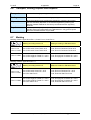
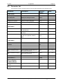
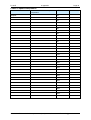
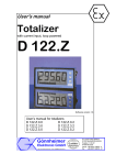
User's manual
Totalizer
with current input, loop powered
D 122.Z
Edition of standards 2010, Software version 1.7
User’s manual for totalizers
D 122.Z.0.x.x
D 122.Z.3.x.x
D 122.Z.5.x.x
D 122.Z
User’s manual
Page 1
Table of contents
1
Operation instruction for Explosion protected device.................................................................. 3
2
Totalizer with current input D 122.Z ................................................................................................ 4
3
2.1
Short description .......................................................................................................................... 4
2.2
Features overview........................................................................................................................ 5
2.3
Conformity with standards ........................................................................................................... 5
Installation and Connection ............................................................................................................. 6
3.1.1
3.1.2
Installation of control panel housing D122.Z.0 und D122.Z.3 .............................................. 6
Connecting of control panel housing D122.Z.0 und D122.Z.3 ............................................. 6
3.2
Installation of field housing D 122.Z.5.......................................................................................... 7
3.2.1
Connecting of field housing D122.Z.0 und D122.Z.3 ........................................................... 7
3.3
Internal zener barrier option......................................................................................................... 8
3.4
Initial operation............................................................................................................................. 9
3.4.1
Default parameters ............................................................................................................... 9
3.4.2
Ex works settings – Device reset.......................................................................................... 9
4
Operating manual............................................................................................................................ 10
4.1
Front view................................................................................................................................... 10
4.2
Keyboard.................................................................................................................................... 10
4.3
Configuration.............................................................................................................................. 11
4.4
Parameter input illustration ........................................................................................................ 14
4.4.1
Hysterese and time delay setting ....................................................................................... 15
4.5
Configuration example ............................................................................................................... 16
5
Flow charts ...................................................................................................................................... 19
6
Appendix .......................................................................................................................................... 27
6.1
Specifications ............................................................................................................................. 27
6.2
Error messages.......................................................................................................................... 28
6.3
Dimensions ................................................................................................................................ 28
6.4
Type code .................................................................................................................................. 29
6.5
Material specification ................................................................................................................. 29
6.6
Transport, Storing, Repairs und Disposal.................................................................................. 30
6.7
Marking ...................................................................................................................................... 30
6.8
Parameter list ............................................................................................................................. 31
6.9
Index .......................................................................................................................................... 33
Gönnheimer Elektronic GmbH
phone: +49(6321)49919-0, fax: -41
Email: [email protected]
D 122.Z
User’s manual
Page 2
The symbols WARNING, CAUTION, NOTE
This symbol warns of a serious hazard. Failure to observe this
warning may result in death or the destruction of property.
This symbol warns of a possible failure. Failure to observe this
caution may result in the total failure of the device or the system or
plant to which it is connected.
This symbol highlights important information.
Gönnheimer Elektronic GmbH
phone: +49(6321)49919-0, fax: -41
Email: [email protected]
D 122.Z
1
User’s manual
Page 3
Operation instruction for Explosion protected device
Application and Standards
This instruction manual applies to explosion-protected control panels of type of protection
types below. This apparatus is only to be used as defined and meets requirements of EN 60
079 particularly EN60 079-14 "electrical apparatus for potentiality explosive atmospheres".
Use this manual in hazardous locations, which are hazardous due to gases and vapours
according to the explosion group and temperature class as stipulated on the type label. When
installing and operating the explosion protected distribution and control panels you should
observe the respective nationally valid regulations and requirements.
General Instructions
The device has to have a back-up fuse as stipulated. The mains connection must have a
sufficient short circuit current to ensure safe breaking of the fuse. To achieve an impeccable
and safety device operation, please take care for adept transportation, storage and mounting,
as well as accurate service and maintenance. Operation of this device should only be
implemented by authorised persons and in strict accordance with local safety standards.
The electrical data on the type label and if applicable, the "special conditions" of the test
certificate Fehler! Unbekannter Name für Dokument-Eigenschaft.are to be observed.
For outdoor installation it is recommended to protect the explosion protected distribution and
control panel against direct climatic influence, e.g. with a protective roof. The maximum
ambient temperature is 40°C, if not stipulated otherwise.
Intrinsically Safe Circuits
Erection instructions in the testing certificates of intrinsically safe apparatus are to be
observed. The electrical safety values stipulated on the type label must not be exceeded in the
intrinsically safe circuit. When interconnecting intrinsically safe circuits it is to be tested,
whether a voltage and/or current addition occurs. The intrinsic safety of interconnected circuits
is to be ensured. (EN 60079-14, section 12)
Safety Measures: to read and to comply
Work on electrical installations and apparatus in operation is generally forbidden in
hazardous locations, with the exception of intrinsically safe circuits. In special cases
work can be done on non-intrinsically safe circuits, on the condition that during the
duration of such work no explosive atmosphere exists. Only explosion protected
certified measuring instruments may be used to ensure that the apparatus is
voltage-free. Grounding and short-circuiting may only be carried out, if there is no
explosion hazard at the grounding or short circuit connection.
Danger of static charge!
Clean only with humid cloth!
Do not open when an explosive dust atmosphere is present!
Gönnheimer Elektronic GmbH
phone: +49(6321)49919-0, fax: -41
Email: [email protected]
D 122.Z
2 Totalizer with current input
2
Totalizer with current input D 122.Z
2.1
Short description
Page 4
The 5-digit totalizer D122.Z operates in hazardous area and indicates the sum of measured values
of a 4 up to 20 mA current circuit. The device gets its energy from the measure circuit, therefore an
extra power supply or batteries are unnecessary. The totalizer measures the current, adds the
previous values, scales the sum and displays the sum finally on the LCD.
The present measured signal is also be displayed on a 41 segment bargraph. It's
possible to scale the bargraph separately to the digital value. The totalizer D122 is
available in several housings.
The totalizer has 2 intrinsically safe alarm outputs as an option (D122.Z.x.2).
These outputs change their state, if the measured value exceeds his alarm limits.
It’s possible to choose open-circuit or closed-circuit connection.
It is possible to refer the alarm monitoring to the sum or to the present measured
value. In the last case the limits are displayed on a second bargraph. On one look
you’re sure that the measured value is in its limits.
Alternative to the option of two digital outputs for external limit monitoring, a control
input and a digital output are implemented to the totalizer D122.Z.x.3. An active
intrinsically safe signal (Low < 2V, High > 5V) on the control input sends a reset
command to the totalizer.
The digital output port can be configured by software in two different modes: As a
setpoint-reached message when the totalizer sum reaches its limit and as a pulse
output for the current flow signal. In this case, the D122 measures the present
flow rate and converts it to a digital signal.
The resolution of the digital signal is directly coupled with the scale configuration of
the totalizer: each increment of the least significant digit sends a pulse. The pulse
width is about 7 ms, by a maximum output frequency of 68 Hz.
The option curve and square root fitting offers a reproduction of an arbitrary
monotone function of measured current and displayed value. A square root fitting
function especial for measuring a flow through an aperture is implemented.
Gönnheimer Elektronic GmbH
phone: +49(6321)49919-0, fax: -41
Email: [email protected]
D 122.Z
2.2
;
Page 5
Features overview
Basic functions
•
•
•
•
•
•
•
;
2 Totalizer with current input
Loop-powered totalizer with current input (4 .. 20 mA)
Connect like passive analogue totalizers, voltage drop ca. 1V
LC-Display, 5 digits, up to 30 mm figure-height
Scale by keyboard and Display
41-segment bargraph for present value observation
Bargraph is scaleable separately
Several housings available (control panel- and field housing)
Options D122.Z.x.2
• Alarm monitoring: two intrinsically safe alarm outputs on the display
• Limit-functions with hysterese and time delay
• Field housing with additional (2nd) PG-Connector
;
Options D122.Z.x.3
• Digital input to receive an external reset signal
• Digital output with 2 configurations: as an sum limit monitor and as quantity
proportional pulse signal
;
Curve fitting Option D122.xS
• Root function
• Curve fitting with any monotone function by using a list of points
2.3
Conformity with standards
The explosion proof indicators type D122.Z meets requirements of listed standards in the attachment
(Declaration of conformity). They were developed, manufactured and tested in accordance with stateof-the-art engineering practice and ISO9001:2008.
Gönnheimer Elektronic GmbH
phone: +49(6321)49919-0, fax: -41
Email: [email protected]
D 122.Z
3
3 Installation and Connection
Page 6
Installation and Connection
3.1.1 Installation of control panel housing D122.Z.0 und D122.Z.3
The totalizers D122.Z.0 and D 122.Z.3 are predicated for installation in a
control panel.
How to insert
the dimension
symbol
Insert the dimension symbol (icon) before mounting. Do this by first removing
the front frame as shown in the figure at left. Now remove the front panel
from the housing as shown in the figure on the right.
Cut the desired dimension-symbol from the set and pull it into its intended
place on the right side of the panel. Make sure that the symbol is facing the
front. Replace the front panel and frame.
How to fix the
device in the
control panel
Fix the device into the control panel with the intend cramps.
3.1.2 Connecting of control panel housing D122.Z.0 und D122.Z.3
Connect the totalizers only to intrinsically safe 4 ...
20 mA current circuits.
The terminals of the totalizers in the control panel housing are shown in
Figure 1. The terminals 5,6 and 7,8 are absent by totalizers without alarm
monitoring.
Gönnheimer Elektronic GmbH
phone: +49(6321)49919-0, fax: -41
Email: [email protected]
D 122.Z
3 Installation and Connection
intrinsically safe
measure circuit 4 ..20 mA
terminals 1,2
Page 7
alarm monitoring option
terminals 5,6: lower alarm
terminals 7,8: upper
alarm
Figure 1: Terminals by totalizers in control panel housing
Please regard the terminal maximum values of the
attached EC- type certificate TÜV 99 ATEX 1488
3.2
Installation of field housing D 122.Z.5
Choose a solid place to install the totalizers in the field area.
How to insert
the dimension
symbol
First, cut the desired dimension symbol out of the set. Then pull off the four
screws of the cap and remove the cap from the housing.
Now push the prepared dimension-symbol into the dimension-symbol-slot.
Make sure that the symbol is facing the front.
The dimension-symbol-slot lies below the display, on the internal side of the
cap.
Finally replace the cup on the housing.
3.2.1 Connecting of field housing D122.Z.0 und D122.Z.3
The terminals of the totalizers with field housing are inside. The placement of
the terminals is shown at the Figure 2..
The terminals 5,6 and 7,8 are absent by totalizers without alarm monitoring.
Connect the totalizers only to intrinsically safe 4 ...
20 mA current circuits.
Gönnheimer Elektronic GmbH
phone: +49(6321)49919-0, fax: -41
Email: [email protected]
D 122.Z
3 Installation and Connection
Page 8
Figure 2: Terminals of D 122.Z.5
Please regard the terminal maximum values of the
attached EC- type certificate TÜV 99 ATEX 1488
3.3
Internal zener barrier option
Devices with type code D122.A.x.x.BM
The standard digital indicator D122 works exclusively in intrinsically safe 4..20 mA current
circuits (Ex i). If the concerned measure current circuit is not intrinsically safe, an extra zener
barrier or an isolated interface and a long additional cable to the interface outside the
hazardous area and back is needed.
In those cases, the option integrated zener barrier
is very practical, because the interface is build in. A
further advantage of an indicator with this option is
that the intrinsical safety proof is not required.
The ignition protection is Ex m [ib] IIC T6 at
ambient temperature of 45°C, Ex m [ib] IIC T5 at
60 °C respectively.
The terminal voltage in the measure circuit with
internal zener barrier option is about 2 V.
Gönnheimer Elektronic GmbH
phone: +49(6321)49919-0, fax: -41
Email: [email protected]
D 122.Z
3.4
3 Installation and Connection
Page 9
Initial operation
After connecting, a display test (all segments of the display are turned on)
appears immediate during one second. Thereupon the display shows the
software version of the indicator.
3.4.1 Default parameters
The following parameters are active ex works:
4 mA curent -> 4.00
Scaling (display and bargraph)
20 mA current -> 20.00
Limits
Low: 4.00 mA / High: 20.00 mA
Hysteresis / Delay
0.10 / 0 sec.
alarm outputs (alarm monitoring)
circuit-opening connection
Code words
CODE1: 0001 / CODE2: 0002
3.4.2 Ex works settings – Device reset
Press the Enter- and Right-button during the start sequence to
reactivate the default parameters. (Hardware-Reset)
A reset activates also the ex works calibration.
Gönnheimer Elektronic GmbH
phone: +49(6321)49919-0, fax: -41
Email: [email protected]
D 122.Z
4 Manual
4
Operating manual
4.1
Front view
4.2
Keyboard
Page 10
On the front side of the totalizer are tree buttons with several function symbols. With these tree
buttons the user can activate each function and enter all parameters for any individual setting.
Each button is named by its function:
Enter-button
Pressing the enter-button starts the input menu.
In general, the enter-button activates the menu item or accepts the
manipulated value of a parameter.
Up-button
Functions of the up-button are:
1. present measure value button
2. modification of the selected figure
3. pass menu items
Right-button
Functions of the right-button are:
1. change the display to limit view
2. select figures
3. pass menu items
Gönnheimer Elektronic GmbH
phone: +49(6321)49919-0, fax: -41
Email: [email protected]
D 122.Z
4.3
4 Manual
Page 11
Configuration
It is easy to set the parameters and change the configuration of the totalizer. The inputs are logical
grouped by a menu structure. The flow charts of these menus can be found at chapter 6.
Totalizers without the alarm monitoring option do not have the
corresponding menu items.
The Input-views in the flow diagrams have additional boxes
in their background, because the Input-views may be changed
by pressing any of the buttons.
The procedure, to enter a value, is shown in the flow diagram ‘Edit
menu’, see Figure 13.
)
Normal state
After connecting, the totalizer D122 starts to initialise its
configuration. The configuration data is stored in an internal
EEPROM due to the previous run. By the first start, the D122.Z
totalizer initialises the default configuration.
Directly past starting sequence the totalizer begins to operate.
This state is called the ‘normal state’ of the D122 and the totalizer
is also ready for inputs.
(See also flow diagram in Figure 7)
)
Present-value control
Pressing and holding the up-button (present value control
button) the display shows the present measured value.
(See also flow diagram in Figure 7)
)
Limit view menu /
Counter reset
One touch on the right-button starts the limit view menu.
Totalizers without the alarm monitoring option propose the counter
reset suggest immediately. This reset will be executed by pressing
the enter-button and entering the right code word.
(See also flow diagram in Figure 8)
LI L
Totalizers with the alarm monitoring option proposes on the other
hand the lower limit. (Note: if the limits refers to the sum then the
lower limit is absent).
The screen shows now [limit low]. Confirm with the enter-button to
display the value of the lower limit.
LI H
To pass the lower limit press the right-button. The menu changes
to the upper limit. The screen shows now [limit high]. Confirm with
the enter-button to display the value of the upper limit.
rESEt
Pressing the right-button for a second time quits the limit view
menu and offers the reset of the counter.
To reset the counter hit the enter-button. The totalizer is now back
Gönnheimer Elektronic GmbH
phone: +49(6321)49919-0, fax: -41
Email: [email protected]
D 122.Z
4 Manual
Page 12
in normal state.
Pass the counter-reset by pressing the right-button, the totalizer
returns to normal state too.
While watching the limit value it is possible to manipulate it by
pressing the enter-button. The view changes to the
;
Edit mode.
_1234
A blinking segment appears below the sign place. Pressing the
right-button selects the figure and the up-button increments the
selected figure. To accept the new limit value, press the enterbutton.
(See also flow diagram in Figure 8
;
Code protection
CodE 2
Before the menu gets to the edit mode the code 2 must be
entered, to prevent a modification by unauthorised persons.
Entering a wrong code word stops the limit view menu
immediately.
The default code 2 is [0002].
The interrogation of code 2 can be switched off by modifying
the code 2 to [0000]. For this reason the flow diagram shows the
code interrogation in stroked dots. To change the code you must
enter the input menu, later in this chapter.
;
Parameter
entering
(See also flow diagram in Figure 9)
Back in the normal state of the totalizer we start the
)
Input menu
CodE 1
by pressing the enter-button.
The configuration of the totalizer is protected against
manipulations by unauthorised persons with the code 1. To get
the input menu enter the code 1 default [0001].
It’s impossible to switch off the code 1 interrogation.
After entering the right code word the totalizer proposes to join
the
SCAL
Scale menu. The figure on the left hand appears on the screen.
To scale the measured current, the bargraph and to set the
decimal point join the scale menu by confirming with the enterbutton.
See also flow diagram in Figure 10).
Gönnheimer Elektronic GmbH
phone: +49(6321)49919-0, fax: -41
Email: [email protected]
D 122.Z
4 Manual
Page 13
Enter the upper scale point correct figured ‘as big as possible’
(the first figures should not be ‘0’)
In this case you get the maximum precision of the totalizer.
tOtAL
Press the right-button to pass the scale menu and select the
second submenu, the total menu. To start the total menu press
the enter-button.
(See also flow diagram in Figure 12)
LI
To pass the total menu press the right-button. The followingsub
menu is called limit menu. This menu is naturally only available
for totalizers with the alarm monitoring option.
In the limit menu the user enters the limits, as well as the
hysteresis and the time delay of the alarm outputs.
(See also flow diagram in Figure 14)
CodE 1
The next two following items allow to manipulate the words for
code 1 and code 2. The enter-button confirms the input and the
corresponding code appears in edit mode.
CodE 2
Remember that the code word [0000] switches off the code 2.
CAL
Finally it’s possible to calibrate the totalizer with the following
submenu called calibration menu.
(See flow diagram in Figure 15)
The totalizer is already calibrated ex-works.
In general, a further calibration is not necessary and only
experienced persons are allowed to calibrate it.
End
Now we reach the end of the input menu. Confirm the end with
the enter-button. The totalizer switches back to normal state.
If you want to repeat the input menu, press the right-button.
If an invalid value is entered for any of the parameters, you will
not be able to quit the input menu. Instead, the program switches
automatically into edit mode to the found invalid value.
Gönnheimer Elektronic GmbH
phone: +49(6321)49919-0, fax: -41
Email: [email protected]
D 122.Z
4.4
;
4 Manual
Page 14
Parameter input illustration
Prescale factor determination (I-fac)
The totalizer D122.Z adds the measured values to a sum and displays it. The measured value always
refers to second, so it is possible to sum short count events. Recording for a long time the sum gets
considerable bigger as the dimension of the present value.
To adjust the summation to each application, a prescale factor (I-fac) divides the sum to the desired
range. Using the prescale factor it is possible to adjustthe dimension of the instantaneous value to
the desired dimension of the sum. The prescale factor V is defined by
V = desired dimension of sum / dimension of the measured value
or
V=
ES
EM ⋅ [s]
Example: An measuring transductor has an output-signal with the dimension g/min. The sum should
have the dimension kg. The right prescale factor is
V=
1000g
kg
=
= 60000 = 6 ⋅ 104 = 6 E 4
1g
g
⋅ [s]
⋅ [s]
60s
min
According to this example the prescale factor V changes to 1000 (1E3) for a transductor
signal with the dimension g/s, respectively 3600 000 (36E5) for a transductor signal with the
dimension g/h.
The format of the prescale factor V is the exponent notation, i.e.
the figures in front of the zeros of V lie by the exponent notation
in front of the „E“ and the quantity of the zeros lie behind the „E“.
;
Creep suppression (StArt)
In some cases, it will be
necessary to ignore a transductor
signal above 4 mA. This threshold
level is named creep suppression
value. The figure on the right
hand shows its function.
Term of the sum
Curve using
creep supp.
Curve using
offset
Edit the creep suppression value
in the total menu.
measurement value
creep supression value
Figure 3: Creep suppression
Gönnheimer Elektronic GmbH
phone: +49(6321)49919-0, fax: -41
Email: [email protected]
D 122.Z
4 Manual
Page 15
4.4.1 Hysterese and time delay setting
Hysterese
A hysteretic curve prevents an
unwanted fast switching of the
alarm outputs.
alarm monitoring lower limit
The switching behavior of the low
alarm (min) shows figure 4. The
switching behavior of the high
alarm (max) shows figure 5.
on
off
measured value
lower limit
Figure 4: Hysteric curve low alarm
alarm monitoring upper limit
hysteresis at upper limit
on
off
measured value
upper limit
Figure 5: Hysteric curve high alarm
alarm monitoring upper limit
Time delay
The span of time ‘te’ is the
difference between the first
exceeding of the measurement
above the upper limit and the
switching of the high alarm (For
the low alarm exists an analogous
‘te’).
time delay te
on
off
time
measured value
upper limit
time
moment of first exceeding
Figure 6: Time delay max respectively min
If the measured current falls below the high limit during ‘te’, the tetimer resets.
Gönnheimer Elektronic GmbH
phone: +49(6321)49919-0, fax: -41
Email: [email protected]
D 122.Z
4.5
4 Manual
Page 16
Configuration example
For a successful parameter input, see the following example of a flow measurement, with alarm
monitoring.
↑ Situation
↑ Adjustment
• Sensor range:
10g/min ... 100g/min
• Alarm by reaching a
throughput rate of
50 kg
• creep suppression:
12g/min
Procedure:
1] Measure range:
010,0 g/min ... 100,0 g/min
for 4 ... 20 mA
2] Bargraph:
010,0 g/min ... 100,0g/min
3] Limits:
Limit relates to the sum (Limit):
50 kg
4] creep suppression:
012,0 g/min
5] Alarm monitoring
mode:
circuit-opening connection
One touch on the enter-button quits the normal state and starts
the input menu.
CodE1
The menu interrogates for code 1.
The default code 1 is [0001].
Enter the right code word using the arrow buttons.
Finally hit the enter-button.
;
Scaling display and bargraph:
SCAL
dP.PoS
...
Join the scale menu pressing the enter-button.
First set the position of the decimal point. The position of the
decimal point will be used for each parameter, like display,
bargraph and limits.
Set the decimal position after the third position (count from left
side), because we will enter [1000] (100 g/min) for the high scale
point afterwards.
Choose the enter-button to edit the decimalpoint position and
press the right-button for three times.
Confirm with the enter-button.
SCA L
Now the [scale point low] view appears.
Edit by pressing the enter-button and enter the lower scale
point
[0100] (10g/min) as follows:
_0400
Press the right-button for two times to select the second figure.
...
0400
Gönnheimer Elektronic GmbH
Now the figure „4“ blinkes.
phone: +49(6321)49919-0, fax: -41
Email: [email protected]
D 122.Z
4 Manual
Page 17
Hit the up-button until ...
...
0100
... the figure „1“ will be adjusted.
Confirm the lower scale point pressing the enter-button. Now
the...
SCA H
... item appears.
Repeat the input procedure for the upper scale point like the
lower scale point. Enter [1000] (100 g/min) for the upper scale
point.
(Confirm by hitting enter-button)
Enter the upper scale point correct figured ‘as big as possible’
(the first figures should not be ‘0’)
In this case you get the maximum precision of the totalizer.
;
bAr L
Now scale the bargraph. Hit the enter-button.
bAr H
Enter [1000] (100g/min) for the upper bargraph scale point.
Enter [0100] (10 g/min) for the lower bargraph scale point.
Confirm by hitting the enter-button
Hitting enter-button accepts and quits the scale menu.
Prescale factor and creep suppression
tOtAL
Start total menu by pressing enter-button.
I-FAC
Press enter-button a further time to edit the prescale factor.
6E4
Enter the value [ 6E4] (60 000) using the arrow-buttons. To
define the correct prescale factor see paragraph 4.4.
Confirm by hitting the enter-button.
StArt
Press now the enter-button to edit the creep suppression value.
Use the arrow-buttons to enter [0120] (12 g/min).
(Confirm by hitting the enter-button.)
LIS Y
Gönnheimer Elektronic GmbH
Finally, let the alarm monitoring refer to the sum. Select [LIS_Y]
using the arrow-buttons and confirm with the enter-button.
phone: +49(6321)49919-0, fax: -41
Email: [email protected]
D 122.Z
4 Manual
PUL
;
Page 18
Totalizer with external reset and current flow signal option
(D122.Z.x.3) have additional the option to configure the digital
output.
Pass this menu item using the right-button, to keep the default
setting: pulse output = no (=false)
Limits, Hysteresis and time delay
Start the limit menu by pressing the enter-button.
The device skips the input of the lower limit, because the limit
refers to the sum.
LI
LI
H
The upper limit input appears.
After hitting the enter-button enter the limit [0050.0] (50 kg) using
the arrow-buttons.
Confirm by hitting the enter-button.
The hysteresis and time delay are also skipped.
Con H
Now choose the circuit-opening connection [nc---] (normaly
closed) using the up-button and confirm by pressing enter-button.
We pass simply the following menu items (manipulate code
words and calibrate) using the right-button.
End
Gönnheimer Elektronic GmbH
Finally quit the scale menu hitting the enter-button.
The totalizer is back in normal state. The changes are
immediately active and will still be active after power off
(disconnecting the totalizer).
phone: +49(6321)49919-0, fax: -41
Email: [email protected]
D 122.Z
5
5 Flow charts
Page 19
Flow charts
Figure 7: Flow diagram normal state
Gönnheimer Elektronic GmbH
phone: +49(6321)49919-0, fax: -41
Email: [email protected]
D 122.Z
5 Flow charts
Page 20
Limit
view menu
START
Totalizer without limits
Totalizer with limits,
limit refers to sum
limits refers to
present measure value
reset
select
limit low
select
limit high
Max
select counter
RESET
Max
Max
display
low limit
display
high limit
interrogate
code 2
false
code word
Ok
Counter, sum
is zero
Max
false
code word
Max
interrogate
code 2
interrogate
code 2
Ok
false
code word
Ok
SET
SET
modify
low limit
modify
high limit
Limit
view menu
END
Figure 8: Flow diagram limit view
Gönnheimer Elektronic GmbH
phone: +49(6321)49919-0, fax: -41
Email: [email protected]
D 122.Z
5 Flow charts
Page 21
Figure 9: Flow diagram input menu
Gönnheimer Elektronic GmbH
phone: +49(6321)49919-0, fax: -41
Email: [email protected]
D 122.Z
5 Flow charts
SET
Scale
menu
START
Page 22
SET
select decimal
point position
SET
select
low scale point
set position
SET
edit low scale point
(4 mA measure cur.)
SET
SET
select
high scale point
SET
edit high cale point
(20 mA measure cur.)
SET
select bargraph
low position
SET
edit bargraph
low position
SET
select bargraph
high position
edit bargraph
high position
Scale
menu
END
Figure 10: Flow diagram scale menu
Gönnheimer Elektronic GmbH
phone: +49(6321)49919-0, fax: -41
Email: [email protected]
D 122.Z
5 Flow charts
Page 23
Alternative (extended) scale menu for special software option only
Figure 11: Flow diagram extended scale menu
Gönnheimer Elektronic GmbH
phone: +49(6321)49919-0, fax: -41
Email: [email protected]
D 122.Z
5 Flow charts
Page 24
Figure 12: Flow diagram total menu
edit values enter code
SET
SET
SET
etc.
sign is
selected
second figure
is selected
first figure
is selected
Menu
END
SET
Menu
END
Menu
END
SET
SET
etc.
sign
is modified
second figure
is modified
first figure
is modified
Menu
END
Menu
END
SET
SET
Menu
END
SET
etc.
first figure
is modified
sign
is modified
Menu
END
etc.
second figure
is modified
Menu
END
etc.
Menu
END
etc.
Figure 13: edit mode
Gönnheimer Elektronic GmbH
phone: +49(6321)49919-0, fax: -41
Email: [email protected]
D 122.Z
5 Flow charts
Page 25
Figure 14: Flow diagram limit menu
Gönnheimer Elektronic GmbH
phone: +49(6321)49919-0, fax: -41
Email: [email protected]
D 122.Z
5 Flow charts
Calibration
menu
START
Interrogate
code
Page 26
false
code
word
Ok
SET
calibration
pass 1
SET
4
mA
order 4 mA
input current
SET
calibration
pass 2
SET
20
mA
order 20 mA
input current
SET
calibration
pass 3
Calibration
menu
END
Figure 15: Flow diagram calibration menu
Gönnheimer Elektronic GmbH
phone: +49(6321)49919-0, fax: -41
Email: [email protected]
D 122.Z
6 Appendix
6
Appendix
6.1
Specifications
D122.Z.0
D122.Z.3
Page 27
D122.Z.5
-
D122.Z.7
Device Group
II 2 (1) G
II 2 (1) GD
Explosion protection
Ex ia IIC T6 Gb at Ta < 45°C
Ex ia IIC T5 Gb at Ta < 60°C
See left + Ex tb
IIIC IP65 T 70°C
EC- type certificate
TÜV 99 ATEX 1488
Display
Digit height
5figure LCD-7-Segment display
15mm
30mm
30mm
-
5
-
30 mm
Display range
-19999 ... +19999
Dimension symbols
Selectable with defined symbols
Decimal points
Selectable by keyboard
Bargraph
41 Segmentes
-
41 Segmentes
Alarm limits display
- Via bargraph
-
- via Bargraph
Versions D122.x.x.2
- Flashing ‘max’ or ‘min’ sign
'Max'- or. 'Min'
Alarm
limit monitoring
By means of intrinsically safe control circuits (e.g. NAMUR or DIN 19234)
Actual value button
Direct display of present measure value in measurement circuit
Measurement circuit
Intrinsically safe measurement circuit 4 ...20 mA; Voltage drop ca. 1V
Measurement circuit
limits
No-load Voltage U0 ≤ 65 V; short-circuit current Ik ≤ 160 mA
Version D122.x.x.2
Internal inductance: ≤ 40 μH, Internal capacitance: ≤ 10 nF,
see certificate TÜV 99 ATEX 1448
Alarm monitoring
limits
By intrinsically safe control circuits
see certificate TÜV 99 ATEX 1448
Housing
Acc. to control-panel
standard DIN 43700
Protection class
Front panel IP 40 up to IP 65
Dimensions HxWxD
[mm]
48x96x62
72x144x80
Cut out dimensions
43,5 x 91,5
66 x 136,5
Material
Fiber opt. strengthened Noryl
Field housing
IP 65
IP 66
133,5x138x64 138x184x64
140 x 140 x 71
ABS
Aluminium
Measuring error
0,1% ± 2 digits referring to measure range
Temperature
< 0,01% of measure range / K
coefficient
Ambient temperature
limit
-10°C ...+45°C for temperature class 6
-10°C ...+60°C for temperature class 5
totalizers for -20°C ambient temperature on inquiry
Gönnheimer Elektronic GmbH
phone: +49(6321)49919-0, fax: -41
Email: [email protected]
D 122.Z
6.2
6 Appendix
Page 28
Error messages
At startup:
Message
Symptom
Bug-fix
Error 1
Error, general device fault
Error 2
The sum from a previous run is lost
Turn off an turn on the device, if the fault
remains, send the device back to
Gönnheimer
press any button, device is ready for run
6.3
Dimensions
Figure 16: Control panel housing cut-out
Figure 17: Field housing
Gönnheimer Elektronic GmbH
phone: +49(6321)49919-0, fax: -41
Email: [email protected]
D 122.Z
6 Appendix
Page 29
(total height)
M16 x 1,5
Figure 18: Aluminum field housing
6.4
Type code
Device series D122 .
.
Device: Indicator .................................................................. .A
Indicator with curve fitting option ................................ .AS
Totalizer ..................................................................... .Z
Totalizer with curve fitting option ................................ .ZS
Housing:
Control panel housing 48 x 96 mm ......................... .0
Control panel housing 72 x 144 mm ...................... .3
Field housing (30 mm figure height) ...................... .5
Field housing (50 mm figure height) ....................... .6
Digital output:
without ................................................................
with 2 digital outputs ...........................................
with reset input and pulse output ........................
Additional option:
.
.0
.2
.3
Internal zener barrier1 .................................................................................... .BM
Internal two wire readings recorder² .............................................................. .MU
1: Not suitable for D122.x.0.x.x
2: For flied housings only, a combination with internal zener barrier (.BM) is not possible
6.5
Material specification
Device type
Material
manufacturing process
D122.x.0.x.x
D122.x.3.x.x
D122.x.5.x.x
D122.x.6.x.x
D122.x.7.x.x
Noryl
Noryl
ABS
ABS
Aluminum
injection die
injection die
injection die
injection die
die-casting
Gönnheimer Elektronic GmbH
phone: +49(6321)49919-0, fax: -41
casting
casting
casting
casting
Email: [email protected]
D 122.Z
6.6
6 Appendix
Page 30
Transport, Storing, Repairs und Disposal
Transport
Vibration-free in origin package, do not pitch, handle carefully
Storing
Store the device dry, inside of the origin package
Disposal
When the explosion proof multipurpose distribution, switching and control
units are eventually disposed of, the national regulations governing the
disposal of waste materials in the country concerned must be rigorously
observed.
Defective parts may only be replaced by the Manufacturer or by personnel
specially trained and supervised by the Manufacturer. Only genuine spare
parts from the Manufacturer may be fitted.
Repairs
6.7
Marking
Marking of device types D122.Z.0.x.x, D122.Z.3.x.x, D122.Z.5.x.x
Marking according to 50014 ff
Marking according to EN 60079 :2010
D122.x.x.x.0
D122.x.x.x.MU
II 2 G; EEx ia IIC T6 bei Ta bis 45°C
II 2 G; EEx ia IIC T5 bei Ta bis 60°C
II 2 G; Ex ia IIC T6 Gb bei Ta bis 45°C
II 2 G; Ex ia IIC T5 Gb bei Ta bis 60°C
D122.x.x.x.BM
II 2 G; EEx ia [ib] IIC T6 bei Ta < 45°C
II 2 G; EEx ia [ib] IIC T5 bei Ta < 60°C
II 2 G; Ex ia [ib] IIC T6 Gb bei Ta < 45°C
II 2 G; Ex ia [ib] IIC T5 Gb bei Ta < 60°C
0044
Marking of device types D122.Z.7.x.x
Marking according to 50014 ff
Marking according to EN 60079 :2010
D122.x.7.x.0
D122.x.7.x.MU
II 2 G; EEx ia IIC T6 bei Ta < 45°C
II 2 G; EEx ia IIC T5 bei Ta < 60°C
II 2 D; Ex IP65 T70°C
II 2 G; Ex ia IIC T6 Gb bei Ta < 45°C
II 2 G; Ex ia IIC T5 Gb bei Ta < 60°C
II 2 D; Ex tb IIIC IP65 T70°C Db
D122.x.7.x.BM
II 2 G; EEx ia [ib] IIC T6 bei Ta < 45°C
II 2 G; EEx ia [ib] IIC T5 bei Ta < 60°C
II 2 D; Ex IP65 T 70°C
II 2 G; Ex ia [ib] IIC T6 Gb bei Ta < 45°C
II 2 G; Ex ia [ib] IIC T5 Gb bei Ta < 60°C
II 2 D; Ex tb IIIC IP65 T70°C Db
0044
Gönnheimer Elektronic GmbH
phone: +49(6321)49919-0, fax: -41
Email: [email protected]
D 122.Z
6.8
6 Appendix
Page 31
Parameter list
The customer is free to use this chart for archiving the parameters of his indicator D122.
Parameter
Description
previous
Display
Value
Scale menu
Decimalpoint position
dP.PoS
Low scale point
Display at 4 mA input current
SCAL L
High scale point
Display at 20 mA input current
SCAL H
Bargraph low position
Display of starting bargraph
bAr L
Bargraph high position
Display at full bargraph
bAr H
Prescale factor
Dvides the actuell measured value
to scale the sum
I-FAC
Creep suppression
To ignore transductor signals below
this value
StArt
0000
Total menu
Alarm refer to the sum
or refer to the present measure
value
LI S Y
LI S n
Limit menu
Low limit
LI L
High limit
LI H
Hysteresis of low limit
HYS L
Hysteresis of high limit
HYS H
Alarm connection of low
limit
Choice between normal open (no)
and normal closed (nc)
Con L
nc
no
Alarm connection of high
limit
Choice between normal open (no)
and normal closed (nc)
Con H
nc
no
Code word Nr. 1
CodE 1
Code word Nr. 2
CodE 2
Only on Option
Sondersoftware
Low scale point root
function
Display at 4 mA input current
roo L
High scale point root
function
Display at 20 mA input current
roo H
Gönnheimer Elektronic GmbH
phone: +49(6321)49919-0, fax: -41
Email: [email protected]
D 122.Z
6 Appendix
Page 32
Linear or square Interpolation
Choice between linear or square
Interpolation
Setpoint
INTER
In 33
In17
400
450
500
550
600
650
700
750
800
850
900
950
1000
1050
1100
1150
1200
1250
1300
1350
1400
1450
1500
1550
1600
1650
1700
1800
1850
1900
1950
2000
Gönnheimer Elektronic GmbH
phone: +49(6321)49919-0, fax: -41
Email: [email protected]
D 122.Z
6.9
6 Appendix
Page 33
Index
present measure value......... 10
—A—
—H—
alarm limit monitoring............ 27
hardware-reset........................9
hysteresis................5, 9, 13, 18
reset ..................................... 11
—L—
—S—
limit high................................11
limit view ...............................20
limit view menu ...............11, 12
lower scale point .............16, 17
scale....4, 12, 13, 16, 17, 18, 22
starting ................................. 11
—M—
temperature.......................... 27
time delay..............5, 13, 15, 18
totalizer .......4, 5, 10, 11, 14, 18
transductor ........................... 14
—B—
bargraph ........... 4, 5, 12, 16, 17
—C—
closed-circuit connection ........ 4
configuration ................... 11, 12
creep suppression ................ 14
current control button............ 10
mounting .................................6
—D—
decimal point ........................ 16
decimalpoint ......................... 16
dimension symbol ............... 6, 7
—E—
ex works ................................. 9
Gönnheimer Elektronic GmbH
—R—
—T—
—N—
NAMUR.................................27
—P—
precision .........................13, 17
prescale factor ................14, 17
phone: +49(6321)49919-0, fax: -41
Email: [email protected]
Non authorized translation
(1)
EC- TYPE- EXAMINATION CERTIFICATE
(Translation)
(2)
Equipment and protective systems intended for use in
potential explosive Atmospheres – Directive 94/9/EC
(3)
EC- type- examination Certificate number
TÜV 99 ATEX 1488
(4)
Equipment:
Digital Indicator Type D122...
(5)
Manufacturer:
Gönnheimer Elektronic GmbH
(6)
Address:
D-Neustadt an der Weinstraße
(7)
This equipment and any acceptable variation thereto are specified in the schedule to
this certificate and the documents therein referred to.
(8)
The TÜV Hannover/Sachen-Anhalt e.V., TÜV CERT-Zertifizierungsstelle, notified body
No. 0032 in accordance with Article 9 of the Council Directive 94/9/EC of March 1994,
certifies that equipment has been found to comply with the Essential Health and
Safety Requirements relating to the design and construction of equipment and
protective systems intended for use potentially explosive atmospheres, given in Annex
II to the Directive.
The examination and test results are recorded in the confidential report No.
99/PX24090
(9)
Compliance with to essential Health and Safety Requirements has been assured by
compliance with:
EN 50 014:1997 EN 50 020:1994 EN 50 028:1988
(10)
If the sign “X” is places after the certificate number, it indicates that the equipment is
subject to special conditions for safe use specified in the schedule to this certificate.
(11)
This EC- type- examination Certificate relates only to the design and construction of
the specified equipment in accordance with Directive 94/9/EC. Further requirements of
this Directive apply to the manufacture and supply of this equipment.
(12)
The marking of the equipment shall include the following:
II 2 (1) G EEx ia IIC T6 bzw. EEx m [ib] IIC T6
TÜV Hannover/Sachen-Anhalt e.V.
TÜV CERT-Zertifizierungstelle
Am TÜV 1
D-30519 Hannover
Hannover, 02.11.1999
Der Leiter
EC-type-examination Certificates without signature and official stamp shall not be valid. The certificates may be circulated only
without alteration. Extracts or alterations are subject to approval by the TÜV Hannover/Sachsen-Anhalt e.V.
Page 1 of 8
Non authorized translation
(13)
SCHEDULE
(14)
(15)
EC- TYPE-Examination CERTIFICATE No. TÜV 99 ATEX 1488
Description of equipment
The digital indicator type D122 ... serves as direct indicator of measured values of
intrinsically safe 4 ..20 mA current circuits in explosive endangered areas.
The maximum ambient temperature is 45°C in temperature class T6 and 60°C in the
temperature class T5.
Electrical details
Supply and
signal current
circuit
(Terminal 1,2)
Exclusive connection to a certificated intrinsically safe
current circuit with the following highest values:
Ui = 65 V
Ii = 160 mA
Effective internal inductivity 40 µH
Effective internal capacity
10 nF
Only Type D122.T.x.x.x
Supply and
signal current
circuit
(Terminal 1,2)
Exclusive connection to a certificated intrinsically safe
current circuit with the following highest values:
Ui = 30 V
Ii = 160 mA
Pi = 1,6 W
Effective internal inductivity 40 µH
effective internal capacity
10 nF
Terminals 3,4
Bridget
Only TYP 122.x.x.x.BM with additional protection type moulding and the sign EEx m
[ib] IIC T6 bzw. EEx m [ib] IIC T5
Input current
circuit (wire)
Um = 250 V and to connect to ground
EC-type-examination Certificates without signature and official stamp shall not be valid. The certificates may be circulated only
without alteration. Extracts or alterations are subject to approval by the TÜV Hannover/Sachsen-Anhalt e.V.
Page 2 of 8
Non authorized translation
Schedule EC- Type- Examination Certificate No. TÜV 99 ATEX 1488
Any types
Alarm current
circuits
(Terminal 5,6; 7,8)
Outputs:
Inputs:
Exclusive connection to a certificated intrinsically current
circuit with the following highest values each current circuit:
Ui = 30 V
Ii = 160 mA
Pi = 850 mW
Ui = 30 V
Effective internal inductivity ≤ 40 µH
the effective internal capacity is negligibly small
All current circuits are safe gavanically separated up to a nominal voltage of 90 V to
each other. The input current circuit by the type D122.x.x.x.BM is internally connected
to the supply and signal circuit.
(16)
Report No. 99/PX24090
(17)
Special conditions for safe area
None
(18)
Essential health and safety requirements
No additional
EC-type-examination Certificates without signature and official stamp shall not be valid. The certificates may be circulated only
without alteration. Extracts or alterations are subject to approval by the TÜV Hannover/Sachsen-Anhalt e.V.
Page 3 of 8
Non authorized translation
1. Amendment
to
the Conformity Certificate Nr. TÜV 99 ATEX 1488
Manufacturer:
Gönnheimer Elektronic GmbH
Dr.-Julius Leber-Str.2
D-67433 Neuststadt/Weinstraße
The digital indicator type D122 can also be manufactured according to the examination
protocol, listed in the associated examination certificate.
The changes concern the enlargement around the type D122.x.7.x.x. and the application of
type in explosion areas by dust up to ambient temperatures of 65°C. The marking for it is:
II 2 D IP 65 T70°C
Bases of the standards: EN 50281 1 1:1999
The electric data and all other information are valid consistently for this supplement.
The test documentation is listed in test report Nr. 04YEX551218
TÜV NORD CERT GmbH & Co. KG
Hannover, 17.02.2004
TÜV CERT-Zertifizierungsstelle
Am TÜV 1
0-30519 Hannover
Tel.: 0511 986-1470
Fax: 0511 986-2555
Der Leiter
EC-type-examination Certificates without signature and official stamp shall not be valid. The certificates may be circulated only
without alteration. Extracts or alterations are subject to approval by the TÜV Hannover/Sachsen-Anhalt e.V.
Page 4 of 8
Non authorized translation
2. Amendment
to
the Conformity Certificate Nr. TÜV 99 ATEX 1488
Manufacturer:
Gönnheimer Elektronic GmbH
Dr.-Julius Leber-Str.2
D-67433 Neuststadt/Weinstraße
The digital indicator type D122 can also be manufactured according to the examination
protocol, listed in the associated examination certificate. The change concerns the
enlargement around the types D122.PA.7.0.0 and D122.FF.7.0.0 for the binding to
intrinsically safe field busses Profibus PA respectively FF.H1.
The application of the supplemental types can occur in explosion-threatened areas,
Which requires devices of the category 2. By the application in areas of explosion-threatened
by dust, the at most allowed ambient temperature is +65°C.
By the application in areas explosion-threatened by gas is the maximum ambient
temperature depending on the temperature class according to the following table:
Temperature classe
T6
T5
Ta
Up to 45°C
Up to 60°C
Electrical data of the types D122.PA.7.0.0 and D122.FF.7.0.0
Signal and power supply circuit
Ex- protection Intrinsically safe EEx ia IIC
(terminal 1,3 and 2,4)
only to the connection in certified intrinsically
safe circuits. Maximum ratings:
U0 = 30 V
I0 = 660 mA
P0 = 1,6 W
max reactances
L0 = 0 µH
C0 = 0 nF
The electrical data remains unchanged.
EC-type-examination Certificates without signature and official stamp shall not be valid. The certificates may be circulated only
without alteration. Extracts or alterations are subject to approval by the TÜV Hannover/Sachsen-Anhalt e.V.
Page 5 of 8
Non authorized translation
2. Amendment to the Conformity Certificate Nr. TÜV 99 ATEX 1488
The marking of the equipment:
II 2 (1) G EEx ia IIC T6 or T5; resp. II 2 D IP65 T70°C
The marking of the further types remain unchanged.
The digital indicator type D122... according to the EC-type certificate TÜV 99 ATEX 1488
incl. 1. and this 2nd supplement also fulfils the demands of
EN 50 014 :1997 + A1+A2
EN 50 020:2002
EN 50 281-1-1:1998+A1
General directives
Intrinsically safe “i”
Electrical devices with protection by case construction and check
All remaining data remain unchanged for this 2. Amendment.
The test documentation is listed in test report Nr. 04YEX551692
TÜV NORD CERT GmbH & Co. KG
Hannover, 03.11.2004
TÜV CERT-Zertifizierungsstelle
Am TÜV 1
0-30519 Hannover
Tel.: 0511 986-1470
Fax: 0511 986-2555
Der Leiter
EC-type-examination Certificates without signature and official stamp shall not be valid. The certificates may be circulated only
without alteration. Extracts or alterations are subject to approval by the TÜV Hannover/Sachsen-Anhalt e.V.
Page 6 of 8
Non authorized translation
3. Amendment
to certification number:
TÜV 99 ATEX 1488
Device:
Manufacturer:
Digital indicator type D122…
Gönnheimer Elektronic GmbH
Dr.-Julius Leber-Str.2
D-67433 Neuststadt/Weinstraße
Germany
8000553381
10.10.2006
Address:
Order Number:
Date of issue:
Changes:
The digital indicator type D122 can also be manufactured according to the examination
protocol, listed in the associated examination certificate. The change concerns the
enlargement around the types D122.PA.7.0.3K and D122.FF.7.0.3K for the binding to
intrinsically safe field busses Profibus PA respectively FF.H1 as a three channel indicator.
The application of the supplemental types can occur in explosion-threatened areas, which
requires devices of the category 2. By the application in areas of explosion-threatened by
dust, the at most allowed ambient temperature is +65°C.
The information to the allowed ambient temperature is valid consistently accordingly of the
second supplement also for the supplemental types.
The electric data of the second supplement are changed as follows or complemented:
Electric data of the types D122. PA.7.0.0, D122.FF 7.0.0, D122. PA.7.0.3K and
D122.FF.7.0.3K:
Signal and power supply circuit
(terminal 1,3 and 2,4)
By the application in by gas explosionthreatened areas in Ex protection
Intrinsically safe EEx ia IIC.
Field device FISCO to the connection with a
device according to the FISCO model or
Only to the connection in certified
intrinsically safe circuits. Maximum ratings:
U0 = 30 V
I0 = 660 mA
max reactances
L0 = 0 µH
C0 = 0 nF
By the application in by dust explosionthreatened areas max. limit input power
P0 = 1,6 W
The electrical data remains unchanged.
EC-type-examination Certificates without signature and official stamp shall not be valid. The certificates may be circulated only
without alteration. Extracts or alterations are subject to approval by the TÜV Hannover/Sachsen-Anhalt e.V.
Page 7 of 8
Non authorized translation
3. Amendment to the Conformity Certificate Nr. TÜV 99 ATEX 1488
The marking of the equipment:
II 2 (1) G EEx ia IIC T6 or T5; resp. II 2 D IP65 T70°C
The marking of the further types remain unchanged.
The digital indicator type D122... according to the EC-type certificate TÜV 99 ATEX 1488
incl. 1. and this 2nd supplement also fulfils the demands of
EN 50 014 :1997 + A1+A2
EN 50 020:2002
EN 50 281-1-1:1998+A1
DIN EN 60079-27:2006
General directives
Intrinsically safe “i”
Electrical devices with protection by case construction and check
Concept for intrinsically safe field bus systems
(FISCO) and concept for non sparking field bus
systems (FNICO)
The test documentation is listed in test report Nr. 06 YEX 553381.
(17)
Special conditions for safe area
None
(18)
Essential health and safety requirements
No additional
TÜV NORD CERT GmbH, Langemarckstraße 20, 45141 Essen, akkreditiert durch die Zentralstelle der Länder für
Sicherheitstechnik (ZLS), Ident. Nr. 0044, Rechtsnachfolger der TÜV NORD CERT GmbH & Co. KG Ident. Nr.
0032
Der Leiter der Zertifizierungstelle
Schwedt
Geschäftsstelle Hannover, Am TÜV 1, 30519 Hannover, Tel.: +49 (0) 511 986-1455, Fax: +49 (0) 511 986-1590
EC-type-examination Certificates without signature and official stamp shall not be valid. The certificates may be circulated only
without alteration. Extracts or alterations are subject to approval by the TÜV Hannover/Sachsen-Anhalt e.V.
Page 8 of 8
EG-Konformitätserklärung
Declaration of conformity / Déclaration de conformité
Communauté Européenne
Anbieter:
Supplier:
Fournisseur
Gönnheimer Elektronic GmbH
Anschrift:
Address:
Adresse:
Gewerbegebiet Nachtweide
Dr.-Julius-Leber-Straße 2
67433 Neustadt/Weinstraße
Produkt:
Product:
Produit:
D122,
Anzeigegerät /Zähler
Das oben beschriebene Produkt erfüllt die Schutzanforderungen der folgenden EG-Richtlinien
/ the product described above complies with the following EG- rules / le produit décrit cidessus accomplit CU- réglementations
2004/108/EG, 93/68/EWG, 94/9/EG
und ist konform mit / and is in conformity with / et est conforme á:
DIN EN 60079-0: 2010, Allgemeine Bestimmungen
DIN EN 60079-11: 2007, Eigensicherheit „i“
DIN EN 60079-18: 2005, Vergusskapselung „m“
DIN EN 61241-1: 2005, Schutz durch Gehäuse "tD"
DIN EN 60079-27: 2006, Feldbussystme FISCO + FNICO
EN 61000-6-4: Fachgrundnorm Störaussendung; Teil 6-4: Industriebereich
EN 61000-6-2: Fachgrundnorm Störfestigkeit; Teil 6-2: Industriebereich
EN 60947-1: Niederspannungs-Schaltgeräte
zusätzliche Angaben / additional information / informations supplémentaires:
Qualitätsmanagement- System nach ISO EN DIN 9001:2008
Anerkanntes Qualitätssicherungssystem nach Richtlinie 94/9/EG
EG- Baumusterprüfbescheinigung / EC- Type certification / Attestation d’examen ce de type
TÜV 99 ATEX 1488
Neustadt, den 11.03.2010
Gönnheimer Elektronic GmbH
EG-Konformitätserklärung; Rev.1