1
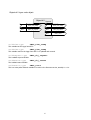
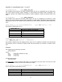
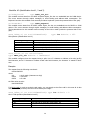
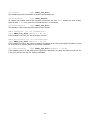
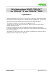
BUILDING AUTOMATION LonServer Field Database Manager User’s Manual Application Program LSRVM03 – November 2001 Important Notice The information included in this document is property of Apice s.r.l and can be changed without notice. Apice s.r.l. will not be liable for errors that might be contained herein and for direct or indirect accidental damage related to the supply, performance or use of the material which this document refers to. It is forbidden to make soft and hard copies of this document, to translate or manipulate all or part of it without the prior written consent of Apice s.r.l. Publications First edition – October 2000 Second edition – March 2001 Third edition – November 2001 Introduction The LonSever is a powerful host-based LONWORKS node specialized in the distributed Field Database (FDB) management. Its primary application is as Access Control Management Unit for up to 8 Gate Controllers in Apice’s Globe2000 Access Control System. The LonServer receives information from the IOL222 Gate Controllers and JLON Identification Units containing the user’s identification data (badge number and/or PIN code), checks the database stored in the on-board memory to understand whether the access must be granted and sends appropriate commands to the Gate Controllers to unlock the protected gates. Every transit occurred in any of the controlled gates will be retained locally in the FDB until the alignment of the distributed FBD and the Local Database (LDB) stored in the Central Management Computer is reached. The alignment of the distributed FDB and LDB is ensured by the AxWin Access Control Software developed by Apice. The Lon Server manages the Users and Badge archives, the Access Level information, the historical transit data retention and anomalous transit conditions in a completely transparent way for the user. The LonServer also manages the messages displayed on the JLON identification units. From the hardware point of view, the node exploits the Neuron Chip for communication purposes only (implements layer 1-6 of the ISO/OSI standard), while all the application is handled by an external 32 bits microcontroller (layer 7). A dedicated operating system called LOS (Lonserver Operating System) has been developed for the node and can be updated through RS232 port or directly from the LonWorks® network, using the AxWin software. This feature makes the LonServer suitable to be adapted for handling many different applications in the Building Automation and Industrial Control fields. Other application-specific operating systems have been developed and customized on demand to meet the requirements of the customer’s application. The node is used in customized versions in the Apice LONWORKS Parking System, in the Central Alarm unit and in the Technological Alarms Monitoring unit for industrial environment. 2 In several applications the Lon Server can be used as Data & Event Logger, storing information in its FDB generated by other devices in the network fed into an external-log input variable. All the commercial versions include an RS232 port for application software upgrading, 128 or 512 kbytes onboard RAM memory with backup lithium battery and real time clock embedded. The internal power supply is obtained through an isolated DC/DC converter, where the incoming voltage can range from 10 to 35 VDC/ 12 to 24VAC. This feature makes the product suitable for working in almost any condition in the Building Automation and Industrial Controls fields. Technical Specifications Power supply Power consumption Transceiver Communication Processor Clock frequency Host Processor Real Time Clock RAM Memory Service Interface Operating Temp. Relative Humidity Enclosure type Enclosure mounting Mechanical Dimensions Application Program Program ID XIF file NV count Alias count Certification 10 – 35 VDC/ 12 to 24VAC internal isolated DC/DC converter 70 mA @ 12V LONWORKS FTT-10 78 Kb/s Neuron Chip 3150 10 MHz 32 bits Microcontroller Chip on-board 128 or 512 Kbytes on board – backup lithium battery Service pin or manual entry – service led on-board 0 – 50° C 20 – 80% non-condensing Plastic blend autoextinguishing Wall mounted or panel mount 150 x 90 x 45 mm LSRVM03 90:0A:0E:00:01:00:10:03 lsrvm03.xif 358 0 CE Installation guidelines The LonServer needs only to be wired on the power supply and provided with a LONWORKS® network connection. The following picture shows the rear view of the LonServer board, where the power supply and the network cables are to be connected. 3 Service PIN Service LED Network + - Power supply RS232 port Pin 2: TX wire Pin 3: RX wire Pin 5 GND wire 2 3 5 Female DB9 connector , to the PC COM port Regarding the power supply connection, please design the power supply line in a way to assure that the node is always powered within the specified operating range. The node is sensitive to the power supply polarity, so it cannot work properly if the supply line is swapped. Anyway, the node is protected against this mis-wiring condition and it does not break down. Neverthless, no guarantee of integrity is provided if the power supply value rings out the spec range or remains mis-wired for a long period of time. As far as the LONWORKS® network connections are concerned, the LonServer node must be wired following the guidelines reported into “Junction Box and Wiring Guidelines for twisted pair LONWORKS® networks” Engineering Bullettin, June 1999. 4 Service Interface The LonServer node mounts both the service LED and the service PIN button on board, for easy installation. This circuitry is not accesible by the outside of the enclosure. Please, make sure the node is installed and commissioned properly before re-mounting the cover and leaving the hardware in its final position. 5 Objects #0 type: node object Object #0 Type #0 nv nvi00time SNVT_time_stamp nv nvo00time SNVT_time_stamp nv nvi00request SNVT_obj_request nv nvo00status SNVT_obj_status nv nvo00version SNVT_count nvi00time type SNVT_time_stamp This variable set the leggo 2000 RTC. nvo00time type SNVT_time_stamp This variable read out the leggo 2000 RTC. It is updated each second. nvi00request type SNVT_obj_request This LonMark request variable. nvo00status type SNVT_obj_status The LonMark status variable. nv00version type SNVT_count This is a const polled network variables. Its value is the firmware version, actually 10 = 10. 6 Objects #1..8 type: Access Controller Object #1 Type: controller nv nvi01pushButton SNVT_lev_disc Identification level 0 int nci01id0Enabled nv nvi01keyboard1 SNVT_str_asc nv nvi01reader1 SNVT_magcard UCPT_id0En Identifier #1 Levels 1, 2 and 3 int nci01id1Enabled1 UCPT_id1En_r1 SNVT_str_asc nci01filter1 UCPT_filter_r1 int nci01id3Enabled1 UCPT_id3En_r1 nv nvi01keyboard2 SNVT_str_asc nv nvi01reader2 SNVT_magcard Identifier #2 Levels 1, 2 and 3 int nci01id1Enabled2 UCPT_id1En_r2 SNVT_str_asc nci01filter2 UCPT_filter_r2 int nci01id3Enabled2 UCPT_id3En_r2 nv nvi01gateFdbk SNVT_lev_disc nv nvo01gateDrive SNVT_lev_disc nv nvi01unlockGate SNVT_lev_disc nv nvo01unlockGate SNVT_lev_disc nv nvi01lockGate SNVT_lev_disc nv nvo01lockGate SNVT_lev_disc int nci01unlockTBand int nci01lockTBand nv nvi01alarmState int Gate control UCPT_unlockTband UCPT_lockTband nv nvo01alarmState int nv nvo01blocked SNVT_lev_disc nv nvo01coercition SNVT_lev_disc nv nvo01denAccess SNVT_lev_disc Alarm control Int nci01alarmAccess UCPT_alarmAccess int nci01effractions UCPT_effractions SNVT_str_asc nci01Coercition1 UCPT_coercition1 SNVT_lev_disc nci01coercition3 UCPT_coercition3 int nci01timeAlarm UCPT_timeAlarm nv int nci01unIdLog int nci01idLog int nci01denAccLog int nci01gateEvLog SNVT_count nci01pgm 7 nvo01diagnostic SNVT_str_asc UCPT_unIdLog UCPT_idLog UCPT_denAccLog UCPT_gateEvLog UCPT_pgm Logger, miscellaneus The access controller object is extremely powerful. The LonServer has 8 different access controllers, each one able of handling one access point. An access point is a gate, a door, a barrier or any other device which needs to be activated through an identification process. The identification process can have 4 different levels: Level Level Level Level 0 1 2 3 means means means means no identification, like a command coming from a push button or a presence detector. the PIN code recognition card recognition card + PIN code recognition Identification levels can be set separately for each access point. They can also be switched automatically from one to the other during the day and the week, and also depending from the alarm state. I.e. each identification level can be always disabled, enabled only in a certain time band or always enabled. The identification level can also be disabled when the alarm is active. Each access point can be driven by one or more pushbuttons and two identifiers. Each identifier is composed of one reader and one keyboard. An interaction with the alarm state is performed when the access is done when the alarm is active. In this case, the alarm status moves into pre-alarm or turn-off conditions. The coercition access can be detected using identification levels 1 and 3. In certain time band, the gate can switch to locked or unlocked state. An accurate event log is performed by object. Three door alarms can be detected using the gate controller built inside the IOL222 node and the access can be logged with the gate result status. When the user inserts the PIN code and makes a number of mistakes greater than the maximum allowed, and effraction is generated and the identifier (reader + keyboard) goes into the blocked status for 3 minutes. This blocked status is read out by a network variable too. An accurate diagnostic network variable allows to simplify installation and start-up operations when the server is not accessible. Network variables description: Identification level 0: nvi01pushButton type SNVT_lev_disc This variable is driven by any LonMark sensor to enable the gate opening. This operation does not identify the user but however can be saved to the event memory (see nci01unIdLog). UCPT_id0En (or nci01id0Enabled) type int default = 255 This variable describes the identification level 0 mode: UCPT_id0En 0 1..64 65..254 255 Description The pushbutton opening is not enabled The pushbutton opening is enabled in time band 1..64 Values not allowed The pushbutton opening is always enabled 8 Identifier #1 (identification level 1, 2 and 3) nvi01keyboard1 type SNVT_str_asc This variable receives data from an APICE keyboard object, like the one embedded into the JLON device. The server answers through explicit messages, to avoid binding and address table consumption. The keyboard bound to this variable works normally as outdoor keyboard. (outside the protected side of the gate). nvi01reader1 type SNVT_magcard This variable receive datas from an APICE reader object, like the one embedded into the IOL222 or JLON devices. The server answers through explicit messages, to avoid binding and address table consumption. The keyboard bound to this variable works normally as the outdoor reader (outside the protected side of the gate). UCPT_id1En_r1 (or nci01id1Enabled1) type int default = 255 PIN operation (identification level 1). UCPT_id1En_r1 0 1..64 65..253 254 255 Description The sole pin operation is not allowed The sole pin operation is allowed in time band 1..64 Value not allowed Only the usage of justification is allowed The sole pin operation is always allowed UCPT_filter_r1 (or nci01filter1) type SNVT_str_asc default = “PPPPCCCC” This variable configures how the magcard string is split. Use a ‘P’ character to indicate a fix code (prefix) field character, and a ‘C’ character to indicate a card code field character; the character ‘0’ stands for don’t care. Example: The magcard has the following record trak: 0010005402356 where: 001 = don’t care (characters to skip) 00054 = card code 02356 = fixed code the filter value must be: 000CCCCCPPPPP If a PX10 reader is used as proximity card reader, you can simply set the filter to X: in this case all 40 bits read out from the proximity card are used to identify the badge. UCPT_id3En_r1 (or nci01id3Enabled1) type int default = 0 Card + PIN operation (identification level 3). UCPT_id3En_r1 0 1..64 65..254 255 Description The PIN code is never required The PIN code is required in time band 1..64 Value not allowed The PIN code is always required 9 Identifier #2 (identification level 1, 2 and 3) nvi01keyboard2 type SNVT_str_asc This variable receives data from an APICE keyboard object, like the one embedded into the JLON device. The server answers through explicit messages, to avoid binding and address table consumption. The keyboard bound to this variable works normally as indoor keyboard. (inside the protected side of the gate). nvi01reader2 type SNVT_magcard This variable receive datas from an APICE reader object, like the one embedded into the IOL222 or JLON devices. The server answers through explicit messages, to avoid binding and address table consumption. The keyboard bound to this variable works normally as the indoor reader (inside the protected side of the gate). UCPT_id1En_r2 (or nci01id1Enabled2) type int default = 255 PIN operation (identification level 2). UCPT_id1En_r2 0 1..64 65..253 254 255 Description The sole pin operation is not allowed The sole pin operation is allowed in time band 1..64 Value not allowed Only the usage of justification is allowed The sole pin operation is always allowed UCPT_filter_r2 (or nci01filter2) type SNVT_str_asc default = “PPPPCCCC” This variable configures how the magcard string is split. Use a ‘P’ character to indicate a fix code (prefix) field character, and a ‘C’ character to indicate a card code field character; the character ‘0’ stands for don’t care. Example: The magcard has the following record trak: 0010005402356 where: 001 = don’t match (characters to skip) 00054 = card code 02356 = fix code the filter value must be: 000CCCCCPPPPP If a PX10 reader is used as proximity card reader, you can simply set the filter to X: in this case all 40 bits read out from the proximity card are used to identify the badge. UCPT_id3En_r2 (or nci01id3Enabled2) type int default = 0 Card + PIN operation (identification level 3). UCPT_id3En_r2 0 1..64 65..254 255 Description The PIN code is never required The PIN code is required in time band 1..64 Not allowed The PIN code is always required 10 Gate controller nvo01gatedrive type SNVT_lev_disc This variable drives the normal opening of the remote gate controller. The output goes to ST_ON and return to ST_OFF value after a while. The gate controller is activated by the rising edge of this variable (update to ST_ON). nvo01unlockGate type SNVT_lev_disc This variable goes to ST_ON when the unlock time band is active or nvi01lockGate goes to ST_ON. The unlock state skip the gate feedback information, saving immediately in the event memory the access request coming from the keyboard or the reader as ‘Transit done’. The door alarms are ingnored, and are not saved if the gate is unlocked. This variable can also be bound to the remote IOL222 gate controller unlock input variable. nvi01unlockGate type SNVT_lev_disc Put the gate unlocked. nvo01lockGate type SNVT_lev_disc This variable goes to ST_ON value when the lock time band is active or nvi01unlockGate goes to ST_ON. The lock state does not allow access from pushbutton, keyboard and reader. This variable can also be bound to the IOL222 gate controller lock input variable. When this variable is ST_ON, the nvo01unlockGate is automatically set to ST_OFF. nvi01lockGate type SNVT_lev_disc Put the gate lock. nvi01gateFdbk type SNVT_lev_disc This variable receives the feedback from the IOL222 gate controller. Although the type is SNVT_lev_disc, the meaning of each value is the following: Value (int) 0 1 2 3 4 5 Value (SNVT_lev_disc) ST_OFF ST_LOW ST_MED ST_HIGH ST_ON NA Description End access Begin access Open door Intruder state Door left open Not transit done The IOL222 gate controller object provides the rigth feedback. The door feedback is used to store the access and door state together and store gate anomalies. To use the feedback, the variable nci01needFdbk must be set to 1. UCPT_unlockTband (or nci01unlockTBand) type int default = 0 A value beetween 1 and 64 is the time band number to unlock gate. When this time band is active, the gate is in unlock state. The value 0 means not used. UCPT_lockTband (or nci01lockTBand) type int default = 0 A value beetween 1 and 64 is the time band number to the lock gate. When this time band is active, the gate is in lock state. The value 0 means not used. 11 Alarm controller nvi01alarmState type SNVT_lev_disc This variable drives the alarm state of the object. Every time the value changes, it is always logged and propagated in nvo01alarmState. nvi01alarmState ST_OFF ST_LOW ST_MED ST_HIGH ST_ON nvo01alarmState Alarm state Off During the turning-on time During the pre-alarm time In alarm On type SNVT_lev_disc This variable is modified either by nvi01alarmState changes or by an access occurring when the alarm is turned-on. In the second case, but not with manual open operation, the event and user identification are logged together. nvo01blocked type SNVT_lev_disc This variable is ST_ON during the security block time and ST_OF during normal operation. See nci01effractions for more information. nvo01coercition type SNVT_lev_disc This variable goes to ST_ON when a coercition event is detected. It remains in this state for nci01timeAlarm , then returns to ST_OFF. nvo01denAccess type SNVT_lev_disc This variable goes to ST_ON if the LonServer detects a number of errors greater than the maximum allowed. It remains in this state for nci01timeAlarm, then return to ST_OFF. UCPT_effractions (or nci01effractions) type int default = 0 When an identifier detects some consecutive access denied operations, it can generate an alarm and/or block itself for 3 minutes. For the PIN code operation, 3 consecutive errors are normally allowed for the first code entrance operation before an error is counted. After the first three mistakes, each mistake is counted as one additional error. bit field 7 A3 6 A2 5 A1 4 A0 3 B3 Max # of mistakes to generate alarm (0= do not generate). 2 B2 1 B1 0 B0 Max # of mistakes to generate block. 12 UCPT_coercition1 (or nci01coercition1) type SNVT_str_asc default = “” This variable contains a coercition code for identification level 1. If the first character is 0 (empty string), the object has not a coercition code for sole PIN operation. UCPT_coercition3 (or nci01coercition3) type SNVT_lev_disc default = ST_OFF When the card+PIN code operation is enabled, this variable allows to distinguish a coercition event when the user digits a PIN+1 code on the keyboard. This requires that the variable is programmed to ST_ON. UCPT_timeAlarm (or nci01timeAlarm) type int default = 5 This variable is used to set the nvo01coercition and nvo01accErr alarm time (in seconds). UCPT_alarmAccess (or nci01alarmAccess) type int default = ? This variable change the access mode for each identifier when alarm is on. bit field 7 A20 6 M22 5 M21 4 M20 3 A10 Identifier 2 MX0 0 1 0 1 0 1 0 1 2 M12 1 M11 0 M10 Identifier 1 MX2 0 0 0 0 1 1 1 1 MX1 0 0 1 1 0 0 1 1 Description Access denied Always allowed normally Allowed with PIN, card and card + PIN Allowed with card or card + PIN Allowed with card + PIN only Access denied Access denied Access denied AX0 0 1 Description After access send alarm in pre-alarm state. After access turn off alarm. Notes: When the alarm is turned on and a pushbutton opening request is received, the alarm rigths for this device are the same as those of identifier 1. Access is allowed to different identification level even if they are normally enabled. If one identificatoion level is normally disabled, when alarm is turned on it continues to be disabled. 13 Logger UCPT_unIdLog (or nci01unIdLog) type int default = 0 Unidentified event logger (pushbutton open) UCPT_unIdLog 0 1..64 65..254 255 Description The pushbutton opening is not saved The pushbutton opening is saved in time band 1..64 Value not allowed The pushbutton opening is always saved UCPT_idLog (or nci01idLog) type int default = 255 Identified event logger. In this version, log of identified access is always enabled and this variable is not used. UCPT_denAccLog (or nci01denAccLog) type int default = 255 Access denied logger. UCPT_denAccLog 0 1..64 65..254 255 Description The access denied are not saved. The access denied saved in time band 1..64. Value not allowed. The access denied are always saved. UCPT_gateEvLog (or nci01gateEvLog) type int default = 1 Gate event logger. UCPT_gateEvLog 0 1..64 65..254 255 Description The gate states are not saved. The gate states are saved in time band 1..64. Value not allowed. The gate states are always saved. When the gate states are saved, an identified event is saved only when gate complete the transaction or when it goes in alarm conditions. Other unidentified gate states are saved as well. When the gate states are not saved, an identified access is saved immediatly after the badge is passed, without waiting for the transaction to complete or alarms to come up. 14 Diagnostic nvo01Diagnostic type SNVT_str_asc This variable provides useful information during the installation and start-up phases. In fact, when an operation fails, the reason is shown in this variable. The meaning of diagnostic messages is the following: Message #01 Pushbutton disabled Means When a pushbutton operation is done but the nci01enable is set to 0 or to an unactive time band number. #02 Pushb. Disabled w/t alarm When a pushbutton operation is done with the alarm turned-on and nci01alarmDsbl set to ST_ON. #03 Object blocked When a PIN or a card read operation is done while the identifier is blocked. The pushbutton operation is not affected by the blocked state. #04 Sole PIN disabled When a sole PIN operation is done but the nci01pinEnabledX variable is set to 0 or to an unactive time band number. #05 PIN disabled w/t alarm A sole PIN operation is attempted when the alarm is turned-on and the nci01disablePinX variable is set to ST_ON value. #06 PIN aborted Not used in this version #07 Wrong PIN detected This error occurs in the first 3 PIN code mistakes. Later the #14.03 message is read out. #08 Coercition detected When a coercition access is detected #09 Access authorized When an allowed access is detected from a keyboard or a card read operation. #10 Pin operation pending When a card read operation is detected but the keyboard is busy in a PIN digit operation. #11 Card filter does not match When a card is read but the record track does not match the filter settings in nci01filterX variable. #12 Reader disabled w/t alar When a card read operation is detected with the alarm turned on but either the reader is disabled (nci01alarmAccX = 0) or the user has not the rigths to turn-off the alarm. The same condition for the keyboard object reads out the #14.04 message. #13 PIN code request The card read operation required PIN code. #14 Access denied This message is not read out in this version. This version uses the #14.XX messages with more details. #15 Gate locked When a pushbutton either a PIN or a card read operations is done when the gate is locked. #14.01 Card unknown The record track matches the filter but not the fixed code field. Set one of the nci09prefX variable to a match fixed code. #14.02 Code unknown The filter and the fixed code match together but the card code is not in memory. Store the card in memory to have access. #14.03 Wrong PIN This message is read out after a wrong PIN operation after the first 3 mistakes. #14.04 No rigth This messages is read out in sole PIN operation with alarm inserted, when the user has not the rigths to turn the alarm off. #14.05 Reader error Not used in this version #14.06 APB error This message is read out when the user data are stored in the memory but the user is not enabled in this identifier (maybe it is in other identifiers) #14.07 Time band This message is read out when the user time band access for this identifier is turned off. #14.08 Expired This message is read out when the user’s badge is expired. (1) #14.09 No credit This message is read out when the user has not an enough credits to complete the current operation. (1) #14.10 Database error This message is read out if an internal database error is detected. (1) The current version does not handle the expiration time band and the credit. This messages will be used in future releases. 15 Object working mode UCPT_pgm (or nci01pgm) type SNVT_str_asc default = 0 This variable is used to change internal object working mode. This firmware version does not handle this value, but the variable is implemented for future use. NOTE: If a keyboard bound is removed or is changed with another keyboard object having different subnet/node address, you must write, using a maintenance tool, the string CLEAR in nviXXkeyboardX network variable to reset the internal address memory buffer. If the local readers and keyboard are used, you need to bind nvo15keyboard output network variable to nviXXkeyboard1 input network variable. In general the local reader (nvo13reader or nvo14reader) bound with the nviXXreader2 network variable uses the keyboard bound in nviXXkeyboard1 network variable. It is possible to distinguish the card sweeping direction in the local reader using nci11pgm configuration network variable. For more details see object 13 and 14. When nvi01alarmState is ST_LOW, it is always possible to turn off the alarm without turning off rigths too. When nvi01alarmState has a value greater than ST_LOW, the user’s turn-off rigths are required and the object must be programmed to allow access with alarm state turned on. 16 Object #9 type: common params access controller Object #9 Type #controller nv nvi09nextEvent SNVT_lev_disc nv nvo09logger SNVT_str_asc nv nvi09rewindLog SNVT_lev_disc nv nvo09logCount SNVT_count nv nvi09memCmd SNVT_str_asc nv nvo09event SNVT_str_asc nv nvi09extLog SNVT_str_asc nv nvo09memRead SNVT_str_asc nv nvo09memCount SNVT_count int nci09pinDigit SNVT_str_asc nci09idleMsg1 SNVT_str_asc nci09idleMsg2 SNVT_str_asc nci09blockMsg1 SNVT_str_asc nci09blockMsg2 SNVT_str_asc nci09insPinMsg1 SNVT_str_asc nci09okMsg1 SNVT_str_asc nci09okMsg2 SNVT_str_asc nci09cardUMsg1 SNVT_str_asc nci09cardUMsg2 SNVT_str_asc nci09codeUMsg1 SNVT_str_asc nci09codeUMsg2 SNVT_str_asc nci09wrongPinMsg1 SNVT_str_asc nci09wrongPinMsg2 SNVT_str_asc nci09noRigthMsg1 SNVT_str_asc nci09noRigthMsg2 SNVT_str_asc nci09rdErrMsg1 SNVT_str_asc nci09rdErrMsg2 SNVT_str_asc nci09notApbMsg1 SNVT_str_asc nci09notApbMsg2 SNVT_str_asc nci09tBandMsg1 SNVT_str_asc nci09tBandMsg2 SNVT_str_asc nci09expiredMsg1 SNVT_str_asc nci09expiredMsg2 SNVT_str_asc nci09noCredMsg1 SNVT_str_asc nci09noCredMsg2 SNVT_str_asc nci09pref1 SNVT_str_asc nci09pref2 SNVT_str_asc nci09pref3 SNVT_str_asc nci09pref4 SNVT_str_asc nci09pref5 SNVT_str_asc nci09pref6 SNVT_str_asc nci09pref7 SNVT_str_asc nci09pref8 Object 9 contains the network variables to handle the memory information concerning the list of enabled cards, the user types and the logger. This object also stores in several configuration network variables the common access control information, like the user messages, the fixed code, etc. 17 LOGGER: nvo09logger type SNVT_str_asc This variable reads out, one record at a time, the log file information. The current record is read out until nvi09nextEvent is updated to ST_ON value. The current record is not the last event happened but the last event read out. When the log file is completely read out, the string EMPTY is sent. The meaning of the various fields is the following: 0 dd 1 2 mm ce 3 Yy 4 hh 5 nn 6 ss 7 8 snd n 9 ev 10 cH 11 cL 12 cL 13 cL 14 cL 15 arg 16 arg 17 arg 18 arg The top row shows the ascii elements of the network variable, the bottom row the field means. dd mm ce yy nn ss snd n ev cH cL arg Day (1..31) Month (1..12) Century (19, 20…) Year (99, 00, …) Minute (00..59) Seconds (00.59) Sender (See table below) Sender number (See table below) Event kynd(See table below) Code High (Used for proximity cards) Code Low Card code in long format. ascii[11] is the MSB, ascii[14] is the LSB. Argument Argument in long format. ascii[15] is the MSB, ascii[18] is the LSB. Senders table: Sender # 1 2 3 4 5 6 Sender Pushbutton controller Keyboard Reader Gate Alarm point Memory Sender number: The sender number is related to the access controller object, as shown in the table: Device/OBJ Pushbutton Keyboard1 Reader 1 Keyboard 2 Reader 2 Gate Memory OBJ1 1 1 1 2 2 1 0 OBJ2 2 3 3 4 4 2 0 OBJ3 3 5 5 6 6 3 0 OBJ4 4 7 7 8 8 4 0 18 OBJ5 5 9 9 10 10 5 0 OBJ6 6 11 11 12 12 6 0 OBJ7 7 13 13 14 14 7 0 OBJ8 8 15 15 16 16 8 0 Event code: The following table shows the event codes. The Cd column, if remarked, means that the event contains the card code identifier. The arg column, if remarked, means that the field can contain an argument field. The X marks mean that the field is optional, while the O marks that is mandatory. The mnemonic column shows the mnemonic event code for the nvo09event variable. # 0 1 2 3 4 5 6 7 8 9 10 11 12 13 14 15 16 17 18 19 20 21 22 23 24 25 26 27 28 29 30 31 32 Description No event Transit done Transit not done Door left open Coercition Intruder door alarm Access denied. Argument shows the cause of refusing Security block of identifier activated Security block end Gate goes in lock state Gate return from the lock state Gate goes in unlock state Gate return from the lock state Pushbutton enable time band goes active Pushbutton enable time band goes not active Sole PIN enable time band goes active Sole PIN enable time band goes not active Card + PIN request time band goes active Card + PIN request time band goes not active Alarm goes into pre-alarm state Alarm is turned off Alarm is turned on Alarm goes in alarm state (obsolete) Alarm is being inserted (exit time) A new card is stored A card in memory has been modified A card in memory has been deleted All card memory has been deleted All log event has been deleted The devices has been overriden with default values Gate close Alarm triggered (Alarm condition detected) Alarm restored (restore normal operation) Cd Arg X X X O X X X X X O X X X X O O O O O Mnemonic NONE PASS NO PASS LEFTOPEN COERCIT INTRUDER See table below BLOCKED UNBLOCKED LOCK ON LOCK OFF UNLK ON UNLK OFF MANU ON MANU OFF PIN ON PIN OFF PINRQ ON PINRQ OF PREALARM ALRM OFF ALRM ON ALARM INSERT STORED EDIT DELETED DEL CARD DEL LOG DEF VAL GATECLS Code field: The code field contains the codeHi and CodeLow when identified people cause the event. For the card memory sender, the code field contains the modified code. Arg field: The transit event can contain an argument, such as justify or debit values (not enable in this version). The access denied event contains the reason of refusing, while the memory event contains the enable capability of the card as 16 bit Hex number, where LSB is the enable flag for identifier 1 and the MSB for the identifier #16. 19 Access denied refusing code: The meaning of each code is shown in the following table: Code 0 1 2 3 4 5 6 7 8 9 10 11 12 Description Coercition Not applicable Card does not match the fixed code Card code not stored in memory Wrong pin No rigths to turn-off the alarm Not applicable Not applicable Card is in memory but is not enabled in this identifier Access time band is not active Card is expired Credit is not enougth Database internal error Mnemonic COERCIT NONE CARD UNK CODE UNK WRONGPIN NO RIGTH NO ERR M NO ERR M NOT APB TM BAND EXPIRED CREDIT DBERROR nvi09nextEvent type SNVT_lev_disc When this variable is updated to ST_ON, the next event is sent to the nvo09logger variable. nvi09rewindEvent type SNVT_lev_disc When this variable is updated to ST_ON, the log is rewound to the oldest event which sent to the nvo09logger variable. nvo09event type SNVT_str_asc This variable is useful in debug session or in start-up operation. This variable is updated with the last event logged and it show the event in the followed format: Sxx-event-codeLow-Arg Where: S Sender identifier (1 character): N = none M = Pushbutton (manual open) K = Keyboard R = Reader G = Gate A = Alarm point E = Memory xx Sender number, 2 characters formatted whith left zero filler. Separator event Mnemonic, 8 characters with left space filler. Separator codeLow Code low, 8 characters whith left zero filler. Separator Arg Argument, 8 character, hexadecimal notation with left zero filler. For details about the sender number and mnemonic, see tables of nvo09logger description above. nvo09logCount type SNVT_count This variable shows the event numer to be read out from the nvo09logger network variable. 20 nvi09extLog type SNVT_str_asc This variable receives external events to be saved in the logger. The used fields are: ascii[0] = sender type ascii[1] = sender number ascii[2] = event Other fields will be used in future releases. CARD MEMORY: nvo09memCount type SNVT_count This variable shows the number of the cards stored in memory. nvi09memCmd type SNVT_str_asc This variable allows to send command to the memory. nvo09memRead type SNVT_str_asc This variable is used to show the command result. Add a card in memory: ascii field 0 A 1 T 2 H 3 E 4 E 5 L 6 L 7 L 8 L 9 P 10 P 11 P 12 P 13 T 14 T 1 2 0 1 A = Character A T = Type (1..16) H = Code high (0..255) EE = Enable flag (16 bits, one for each identifier, see below) LLLL = Code low, 4 bytes long. ascii[5] = MSB, ascii[8] = LSB. PPPP = PIN code, 4 bytes long. ascii[9] = MSB, ascii[12] = LSB. TT = Tag, 2 bytes long. ascii[13] = MSB, ascii[14] = LSB. Enable flag details: ascii[3] 7 6 16 15 5 14 4 13 3 12 2 11 1 10 0 9 ascii[4] 7 6 8 7 5 6 4 5 3 4 2 3 The top row shows the ascii[] element in the network variable, while the middle row shows the bit number, where bit 7 is the MSB. The lower row is the related identifier number. If the bit is set to 1 the card is enabled in the identifier, otherwise if the bit is set to 0, the card is not enable in the identifier. Results: The nvo09memRead variable shows the results: OK: STORED ER: PIN EXSIST ER: MEMORY FULL If the card is stored in memory If the card is not stored because the PIN code already exsists. If the memory buffer is full 21 Update card in memory: This command is similar to the previous one but in this case the sent enable flag are or(ed) with the enable flag stored in memory. To distinguish with the previous command, the update card start with the character U. ascii field 0 U 1 T 2 H 3 E 4 E 5 L 6 L 7 L 8 L 9 P 10 P 11 P 12 P 13 T 14 T 15 P 16 T 17 T 16 T 17 T Results: This command has the same results of the previous command. Check card in memory: This command is used to test if a card is stored in memory. ascii field 0 C 1 - 2 H 3 - 4 - 5 L 6 L 7 L 8 L Results: ER: NOT IN MEMORY If the card is not found in memory. If the card is found, the result will be OK followed by all the card info, as shown below: ascii 0 field O 1 K 2 : 3 4 T 5 H 6 E 7 E 8 L 9 L 10 L 11 L 12 P 13 P 14 P Remove a card from memory: This command is used to remove a card from the memory. ascii field 0 D 1 - 2 H 3 - 4 - 5 L 6 L 7 L 8 L Results: OK: DELETED Even if the card is not found in memory. Read card memory at n position: ascii field 0 R 1 x 2 x 3 x … … … ‘\0’ The xxx.. is an ASCII string, zero ending, showing the position to be read. Results: ER: NOT IN MEMORY If the position is greater then the number of cards stored in memory. If the card is found, the message is OK followed by all the card info, as shown below: ascii 0 field O 1 K 2 : 3 4 T 5 H 6 E 7 E 8 L 9 L 22 10 L 11 L 12 P 13 P 14 P 15 P USER TYPE MEMORY: The user type memory is handled through the nvi09memCmd and nvo09memRead network variables too. The command provided to handle this memory is the F command, as shown below: Write a user type: This command changes the access time band and the alarm rigths of an user type into an identifier. ascii field 0 F 1 u 2 u 3 . 4 i 5 i 6 , 7 f 8 f 9 , 10 a 11 \0 Where: F uu . ii , ff a \0 Command character User type, using two characters with left zero filled (1..16). Separator Identifier number, using two characters with left zero filled (1..16). Separator User uu, identifier ii access time band (0..32) Alarm rigth (0..3): 0 = NONE 1 = ONLY INSERT 2 = INSERT AND UNINSERT 3 = ALL Null terminator Results: ER: WRONG FORMAT ER: WRONG ARGUMENTS ascii field 0 F 1 u 2 u if the ascii[3] or ascii[9] or ascii[11] don’t matches. if the arguments are out of range Or if the command is executed: 3 . 4 i 5 i 6 , 7 f 8 f 9 , 10 a 11 \0 Delete an user type: This command restores the no access time band and the no alarm rigths for an user into an identifier. ascii field 0 F 1 u 2 u 3 . 4 i 5 i 6 D In delete command, 0 values are allowed in uu and ii fields. 0 value means all like in examples: F01.01D F01.00D F00.01D F00.00D delete delete delete delete the user type 1 in identifier 1 the user type 1 in all identifiers all user types in identifier 1 all user types in all identifiers Results: ER: WRONG FORMAT if ascii[3] does not match. OK: TYPE uu DEL KEYB ii OK: TYPE uu DEL ALL KEYB OK: KEYB ii DEL ALL TYPES OK: DEL ALL TYPES ALL KEYB 23 Read user type: To read an user type use the following command: ascii field 0 F 1 u 2 u 3 . 4 i 5 i 6 ? Results: ER: WRONG FORMAT ER: WRONG ARGUMENTS ascii field 0 F 1 u 2 u if ascii[3] doesn’t match. if arguments are out of range Or if the command is executed: 3 . 4 i 5 i 6 , 7 f 8 f 9 , 10 a 11 \0 PASSWORD PROTECTED OPERATIONS: Using nvi09memCmd is possible to erase all the card memory, all the event memory and to restore the LonServer to the default values (factory defaults). To do this, the password is required. The default value is 123456. Delete card memory: ascii field 0 M 1 C 2 x 3 x 4 x 5 x 6 x 7 x xxxxxx = password (6 characters) Results: ER: WRONG PASSWORD OK: CLEAR CARD MEMORY if the password is not correct if the password is fine Delete event memory: ascii field 0 M 1 E 2 x 3 x 4 x 5 x 6 x 7 x xxxxxx = password (6 characters) Results: ER: WRONG PASSWORD OK: CLEAR LOG MEMORY if the password is not correct if the password is fine Restore default: ascii field 0 M 1 A 2 x 3 x 4 x 5 x 6 x 7 x xxxxxx = password (6 characters) 24 Results: ER: WRONG PASSWORD OK: DEFAULT RESTORED if the password is not correct if the password is fine Change password: ascii field 0 M 1 P 2 x 3 x 4 x 5 x 6 x 7 x 8 , 9 n 10 n 11 n 12 n 13 n 14 n xxxxxx = password (6 characters) nnnnnn = new password (6 characters) Results: ER: WRONG PASSWORD OK: PASSWORD CHANGED if the password is not correct if the password is fine CONFIGURATION NETWORK VARIABLES UCPT_pinDigits (or nci09pinDigit) type int default = 5 The digit number of PIN (3..9) UCPT_idleMsg1 (or type SNVT_str_asc UCPT_idleMsg2 (or type SNVT_str_asc nci09idleMsg1) default = “#D#PASSARE TESSERA” nci09idleMsg2) default = “<- <- <- <- <-” Idle message row 1 and 2. The #D# means print date and time in the first row of the local display. If the local keyboard is used, the idle message in local display will be date and time in the first row and the rest of string in nci09idleMsg1 the second row. JLON ignore the #D# command. UCPT_blockMsg1 (or nci09blockMsg1) type SNVT_str_asc default = “ EFFRAZIONE” UCPT_blockMsg2 (or nci09blockMsg2) type SNVT_str_asc default = “ATTENDERE PREGO” Identifier blocked message, row 1 and 2. UCPT_insPinMsg1 (or nci09insPinMsg1) type SNVT_str_asc default = “INSERIRE CODICE” Insert PIN request, only row 1. UCPT_okMsg1 (or nci09okMsg1) type SNVT_str_asc default = “ENTRARE UCPT_okMsg2 (or nci09okMsg2) type SNVT_str_asc default = “” PREGO” Access allowed message, row 1 and 2. UCPT_cardUMsg1 (or nci09cardUMsg1) type SNVT_str_asc default = “CODICE O CARTA” UCPT_cardUMsg2 (or nci09cardUMsg2) type SNVT_str_asc default = “ SCONOSCIUTI” 25 Access denied for unknow card, row 1 and 2. UCPT_codeUMsg1 (or nci09codeUMsg1) type SNVT_str_asc default = “ UTENTE NON” UCPT_codeUMsg2 (or nci09codeUMsg2) type SNVT_str_asc default = “ ABILITATO” Access denied for code unknown, row 1 and 2. UCPT_wrongPinMsg1 type SNVT_str_asc UCPT_wrongPinMsg2 type SNVT_str_asc (or nci09wrongPinMsg1) default = “CODICE PIN” (or nci09wrongPinMsg2) default = “ERRATO” Wrong PIN message, row 1 and 2. UCPT_noRightMsg1 (or nci09noRigthMsg1) type SNVT_str_asc default = “ACCESSO NEGATO” UCPT_noRightMsg2 (or nci09noRigthMsg2) type SNVT_str_asc default = “ALLARME INSERITO” No enougth rigth to access with alarm on, row 1 and 2. UCPT_rdErrMsg1 (or nci09rdErrMsg1) type SNVT_str_asc default = “ERRORE LETTURA” UCPT_rdErrMsg2 (or nci09rdErrMsg2) type SNVT_str_asc default = “PROVARE DI NUOVO” Card doesn’t match the filter message, row 1 and 2. UCPT_notApbMsg1 (or nci09notApbMsg1) type SNVT_str_asc default = “PERCORSO” UCPT_notApbMsg2 (or nci09notApbMsg2) type SNVT_str_asc default = “NON CORRETTO” Card enabled but not in this identifier message, row 1 and 2. UCPT_tBandMsg1 (or nci09tBandMsg1) type SNVT_str_asc default = “FASCIA ORARIA” UCPT_tBandMsg2 (or nci09tBandMsg2) type SNVT_str_asc default = “NON VALIDA” Access time band not active message, row 1 and 2. UCPT_expiredMsg1 (or nci09expiredMsg1) type SNVT_str_asc default = “VALIDITA’” UCPT_expiredMsg2 (or nci09expiredMsg2) type SNVT_str_asc default = “SCADUTA” Card expired message, row 1 and 2. UCPT_noCredMsg1 (or nci09noCredMsg1) type SNVT_str_asc default = “CREDITO UTENTE” UCPT_noCredMsg2 (or nci09noCredMsg2) type SNVT_str_asc default = “INSUFFICENTE” Not enougth credit message, row 1 and 2. UCPT_pref1 (or nci09pref1) type SNVT_str_asc default = “” Fix code # 1. 26 UCPT_pref2 (or nci09pref2) type SNVT_str_asc default = “” Fix code # 2. UCPT_pref3 (or nci09pref3) type SNVT_str_asc default = “” Fix code # 3. UCPT_pref4 (or nci09pref4) type SNVT_str_asc default = “” Fix code # 4. UCPT_pref5 (or nci09pref5) type SNVT_str_asc default = “” Fix code # 5. UCPT_pref6 (or nci09pref6) type SNVT_str_asc default = “” Fix code # 6. UCPT_pref7 (or nci09pref7) type SNVT_str_asc default = “” Fix code # 7. UCPT_pref8 (or nci09pref8) type SNVT_str_asc default = “” Fix code # 8. 27 Object #10 type: time band controller Object #10 Type: controller nv nvi10tBand SNVT_str_asc nv nvo10tBand SNVT_str_asc nv nvo10tb61 SNVT_lev_disc nv nvo10tb62 SNVT_lev_disc nv nvo10tb63 SNVT_lev_disc nv nvo10tb64 SNVT_lev_disc The time band controller handles up to 64 differents weekly time bands. Time bands can be used by all the access control objects. In order to provide general purpose time band outputs, time bands state 61 to 64 are read out using 4 SNVT_lev_disc network variables. Each time band has 4 weekly time intervals. When one time interval is active, the whole time band is active as well. nvi10tBand type SNVT_str_asc This variable is used to add, delete and show a time band. See command description below. nvo10tBand type SNVT_str_asc This variable shows the command results provided by nvi10tBand. See command description below. nvi10tb61 type SNVT_lev_disc This variable shows the time band #61 state. ST_ON means time band active. nvi10tb62 type SNVT_lev_disc This variable shows the time band #62 state. ST_ON means time band active. nvi10tb63 type SNVT_lev_disc This variable shows the time band #63 state. ST_ON means time band active. nvi10tb64 type SNVT_lev_disc This variable shows the time band #64 state. ST_ON means time band active. 28 COMMAND DESCRIPTION: Add time interval: The command syntax to provide to the variable nvi10tBand is: ff.i,hh:mm,HH:MM,days Where: ff . i , hh:mm HH:MM Days time band number(1..64) dot separator time band interval(1..4) Comma separator Starting time in 24 hour notation Ending time in 24 hour notation. List of the enabled days. 7 characters where the character 0 is used for not enabled days and the character 1 for enabled days. The first character is for Sunday, the second for Monday…; the last one is for Saturday. Example: Ending time Starting time Sunday Interval #1 Saturday Time band #1 01.1,08:20,12:45,0111110 The time interval #1 in the time band #1 is set from 8:30 to 12:45 from Monday to Friday. Results: The variable nvo10tBand shows the command results. ff.x,WRONG ARGUMENT xx.i,WRONG ARGUMENT ff.i,WRONG FORMATTED ff.i,WRONG TIME ARGUMENT WRONG COMMAND FORMAT ff.i,hh:mm,HH:MM,days,[ON|OFF] the interval is out of range. the time band is out of range. the ascii[7] or [10] or [13] or [16] do not match. time argument are inconsistent. ascii[5] does not match. on command success. The ON or OFF state show the interval activation state. 29 Query a time band: With this command we can query the time band activation state or the details for each interval. ff.i? (1 <= i <= 4) ff.0? (i = 0) shows the interval details shows the time band activation Results: ff.x,WRONG ARGUMENT xx.i,WRONG ARGUMENT WRONG COMMAND FORMAT ff.i,hh:mm,HH:MM,days,[ON|OFF] ACTIVE NOT ACTIVE the interval is out of range. the time band is out of range. ascii[5] does not match. for detail view for time band query with time band active for time band query with time band not active Delete a time band: ff.iD (1 <= i <= 4) ff.0D i = 0 delete the interval delete the time band Results: ff.x,WRONG ARGUMENT xx.i,WRONG ARGUMENT WRONG COMMAND FORMAT ff.0,DELETED ff.i,DELETED the interval is out of range. the time band is out of range. ascii[5] does not match. time band deleted single time interval deleted 30 Object #11 type: special purpose presence controller Object #11 Type: controller nv nvi11select int nv nvo11count SNVT_count nv nvi11resetArea SNVT_lev_disc nv nvo11cardInfo SNVT_switch nv nvi11reset SNVT_lev_disc nv nvo11alarmState SNVT_lev_disc nv nvi11alarmState SNVT_lev_disc SNVT_lev_disc nci11useObject SNVT_lev_disc nci11autoTurnOn SNVT_lev_disc nci11autoTurnOff SNVT_count nci11pgm UCPT_useObject UCPT_autoTurnOn UCPT_autoTurnOff UCPT_pgm This special controller is used to count people inside a certain area. This kind of controller works in several modes, related to the nci11pgm value. At the moment only mode 0 and 1 are enabled. The value 1 is related to card direction detection (see objects 13 and 14 for more details). Working mode 0: The object can handle up 20 areas, each area containing up to 15 peoples. When the user accesses through either reader1 or keyboard1 of any access control object, the area related to the user’s card memory tag field is incremented of his presence. If the user was already present in the area, the count is not incremented. The same happens when the user accesses through either reader2 or keyboard2, but this time the count is decremented, if the user was present in the area. When all areas are empty, the object can turn the alarm on. If nobody was present in the area and the alarm was turned on, as soon as an authorised user with enough rights enter the area the alarm can be immediately turned off. nvi11select type int This variable allows to chose the area. nvi11resetArea type SNVT_lev_disc When this variable receive an ST_ON update, the selected area is reset to 0 (no presence); if all areas are zero and the nci11autoTurnOn = ST_ON, the alarm is turned on. nvi11reset type SNVT_lev_disc When this variable receive an ST_ON update, all areas are reset to 0 (no presence everywhere) and the alarm is turned on (provided that nci11autoTurnOn = ST_ON). nvi11alarmState type SNVT_lev_disc This variable receives the alarm state from other objects. 31 nvo11count type SNVT_lev_disc This variable shows the total number of people in the selected area. nvo11cardInfo type SNVT_switch On update, this variable sends areas occupancy information: the term value contains the area number, while the term state is 0 if the area is unoccupied and 1 is it is occupied. nvo11alarmState type SNVT_lev_disc This variable is used to send the alarm status to other objects. UNVT_useObject (or nci11useObject) type SNVT_lev_disc default = ST_ON If this variable is set to ST_OFF the object does not work. UNVT_autoTurnOn (or nci11autoTurnOn) type SNVT_lev_disc default = ST_ON If this variable is set to ST_ON, when no presence is detected in all areas (unoccupied), the alarm is turned on. If it is set to ST_OFF the auto turn-on function is disabled. nci11autoTurnOff type SNVT_lev_disc default = ST_ON If this variable is set to ST_ON, when the first presence is detected in one area, the alarm is turned off. If it is set to ST_OFF the auto turn-off function is disabled. 32 Object #12 type: controller Object #12 Type controller nv nvi12com SNVT_str_asc nv nvo12com SNVT_str_asc This controller is able to estabilish a cominication with other LonServers. For more details see the system guide. nvi12com type SNVT_str_asc This variable receives information from other LonServers. nvo12com type SNVT_str_asc This variable sends information to other LonServers. 33 Object #13 type: Controller This object interfaces the optional embedded reader in the LonServer device. Object #13 Reader controller nv Nvo13reader SNVT_magcard Magcard or proximity card embedded reader nvo13magcard type SNVT_magcard Each time a card is run in the slot or a proximity card is detected, the nvo13magcard network variable is updated. It can be bound to an access control object reader input. (if nci11pgm = 0) If nci11pgm = 1 running the card from rigth to left updates nvo13reader network variable, running card from left to rigth updates nvo14reader network variable. This allows to see two virtual different readers depending from the sweeping direction. 34 Object #14 type: Controller This object interfaces the optional external local reader. Object #14 Reader controller nv Nvo14reader SNVT_magcard Magcard or proximity card embedded reader nvo14magcard type SNVT_magcard Each time a card is run in the slot or a proximity card is detected, the nvo14magcard network variable is updated. It can be bound to an access control object reader input. (if nci11pgm = 0) If nci11pgm = 1 running the card from rigth to left updates nvo13reader network variable, running the card from left to rigth updates nvo14reader network variable. This allows to see two virtual different readers depending from the sweeping direction. 35 Object #15 type: Controller This object interface the local keyboard. Object #15 Keyboard controller nv 1 2 3 4 5 6 7 8 SI 9 0 NO Nvo15keyboard SNVT_str_asc JLON keyboard Nvo15keyboard type SNVT_str_asc Each time a key is digit on keyboard, the nvo15keyboard network variable is updated. The key pressed is added to the end of the string nvo15keyboard.ascii until a maximum 30 allowed characters are not reached. When the string is full, all characters shift by one position and the new data is added to the last position. Example 1: Used press 4, 2, 5, 8 keys, nvo15keyboard.ascii = 4258 Example 2: nvo15keyboard.ascii = 4258..456 User press key 1 Nvo15keyboard.ascii = 258..4561 The oldest key is thrown away (full) (full) The new key is stored at the end It can be bound to any access control object keyboard input. 36 Apice Building Automation Via G.B. Vico 45b – 50053 Empoli (FI) - Italy Phone +39 0571 920442 Fax +39 0571 920474 email: [email protected] Home page: www.apice.org 37