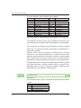
1
MDUG-CM1/11401E-01
Ver.2.29 / 2.39
Muscle Corporation Inc.
©2009 Muscle Corp. All rights reserved
COOL MUSCLE USER'S GUIDE
WARNING
Do not impact the motor.
Impacting motor may cause the driver case and the sensor mounted on the back of the motor to move, resulting in alignment errors.
Do not rotate the shaft of the motor when it is not powered on. Rotating the shaft over 400rpm when the Cool Muscle is not powered
on may cause regenerated voltage within the motor. This regenerated voltage may damage the driver board.
Use regulated power supply
Please make sure to use Regulated DC+24V power supply. Sudden spikes that non-regulated power supplies may cause damage
to the motor.
Do not use the motor in wet condition
Standard Cool Muscle motors are not environmentally sealed. Using the motor in wet condition may damage the motor.
Use the motor within its specification
Please refer to the spec section of this manual and ensure that the
motor is used within these specifications.
Are cables too long?
The recommended length of motor cable is 3m and the power
cable is 2m. If a longer cable is required, please follow the instructions in this manual.
Do not connect or disconnect the motor when the motor is powered
on. This may cause damage to the motor.
When an alarm occurs, re-start operation after removing its cause.
When operation is continued with a cause of alarm, damage to
mechanical equipment could occur.
WA-1
COOL MUSCLE USER'S GUIDE
Disclaimer
Before operation of Cool Muscle, it is very important that you read
the User Manual thoroughly. The Cool Muscle can cause bodily
injury and/or equipment damage if it is misused. Proper safety
means and measures should be provided to prevent any misuse
and/or improper operations. The user assumes all liabilities for its
use. The Cool Muscle shall not be used for mission critical applications without explict written permission from Muscle Corporation.
Copyright
This user's guide is copyrighted by Muscle Corporation. All rights
reserved.
Information on this document is subject to change without notice.
Coolmuscle is trade mark of Muscle Corporation.
Microsoft and Windows are registered trademarks of Microsoft
Corporation in the United States and other countries.
Other company names and product names described in this
document are trademarks or registered trademarks of their
respective holders.
The trademarks notices (™, ®) are not necessarily appended to
company, system, and product names described in this document.
Printed in Japan.
WA-2
COOL MUSCLE USER'S GUIDE
ABOUT USER'S GUIDE
Welcome to the Cool Muscle integrated motor. The Cool Muscle
Refer to the sections
applicable to your
Motor Type
User's Guide provides you with hands-on instructions to help you
set up your hardware, set parameters, create / edit command programs and make the most of the Cool Muscle motors.
Since this User's Guide is organized to follow the set up process
P Pulse
V Analog
described in this flow chart.
C Computer
Flow chart of SECTION
SECTION1
P
V
C
The features of Cool Muscle are explained.
The differences between 3 types, P, V and C, of Cool
Muscle’s interfaces.
SECTION2
P
V
C
V
C
V
C
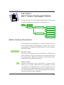
Setting Up Cool Muscle
Please see how to connect Cool Muscle with the attached
cables. The other components are shown separatelly.
SECTION4
P
When You Receive Cool Muscle
When receiving the Cool Muscle, please confirm that
there are all components in a package. Then connect
Cool Muscle with a PC and confirm the communication.
SECTION3
P
About �����������
Cool Muscle
Input and Output
Learn how to cotrol I/O ports and set functions for each
I/O port.
SC0-3
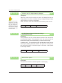
COOL MUSCLE USER'S GUIDE
SECTION5
P
V
C
Communication Method with Cool Muscle is introduced.
The outline of special software, Cool Works Lite and the
communication method with Hyper Terminal.
SECTION6
P
V
C
V
C
V
C
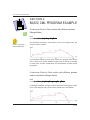
Basic CML Program Example
Guide for programming by CML commands referring to
program examples.
The program for network is also explained.
SECTION10
C
Setting Commands
The details of commands. Operation of Cool Muscle by
commands and the programming method are explained.
(Reference: Appendix3 “Command List”)
SECTION9
C
Setting Parameters
Set parameters to make the Cool Muscle suit your
specification. Learn how to set the parameters. This
section also lists all the parameters available.
(Reference: Appendix2 “Parameter List”)
SECTION8
P
CML Structure
The composition of special programming language, CML (Cool
Muscle Language). The form of parameters and commands
and the editing method by a text editor are introduced.
SECTION7
P
Communication Method
Applied CML Program Example
Specified program examples with parameter and command
settings are shown and the detail of actual motion is
explained. Please refer for a further comprehension.
SC0-4
COOL MUSCLE USER'S GUIDE
INDEX
WARNING .................................................................................................... WA-1
Disclaimer .........................................................................................................................WA-2
Copyright ...........................................................................................................................WA-2
ABOUT USER'S GUIDE . ............................................................................SC0-3
Flow chart of SECTION . ................................................................................................. SC0-3
SECTION 1
ABOUT COOL MUSCLE ................................................................................................. SC1-8
Cool Muscle Interface ................................................................................................ SC1-8
SECTION 2
WHEN YOU RECEIVE COOL MUSCLE . ......................................................................SC2-11
Cool Muscle Package ...............................................................................................SC2-11
Components ............................................................................................................. SC2-12
SECTION 3
SETTING UP COOL MUSCLE . .................................................................................... SC3-13
How To Connect Cool Muscle .................................................................................. SC3-13
Communication with Cool Muscle ............................................................................ SC3-18
Trouble Shooting of Communication ........................................................................ SC3-19
SECTION 4
INPUT AND OUTPUT ................................................................................................... SC4-20
Pin Assignment and Layout . .................................................................................... SC4-20
Assignable Functions-Input ...................................................................................... SC4-21
Assignable Functions-Output ................................................................................... SC4-23
SECTION 5
COMMUNICATION METHOD ....................................................................................... SC5-24
CoolWorks Lite ......................................................................................................... SC5-24
How to Set Up Hyper Terminal ................................................................................. SC5-27
IN-5
COOL MUSCLE USER'S GUIDE
SECTION 6
CML STRUCTURE . ...................................................................................................... SC6-31
Cool Muscle Language ............................................................................................ SC6-31
Parameters . ............................................................................................................. SC6-32
Commands ............................................................................................................... SC6-32
CML Structure .......................................................................................................... SC6-33
CML File Structure - Program Mode ........................................................................ SC6-35
CML Program File Example ..................................................................................... SC6-36
CML File Structure - Direct Mode . ........................................................................... SC6-37
CML File / Command Downloading . ........................................................................ SC6-38
SECTION 7
SETTING PARAMETERS ............................................................................................. SC7-39
Before Setting Parameters ....................................................................................... SC7-39
Parameter Structure ................................................................................................. SC7-41
Parameter ................................................................................................................ SC7-42
SECTION 8
SETTING COMMANDS ................................................................................................ SC8-68
Direct Mode - Data Commands . .............................................................................. SC8-69
Direct Mode - Execution Commands ....................................................................... SC8-70
Direct Mode - Query ................................................................................................. SC8-73
Program Mode - Data Commands ........................................................................... SC8-75
Program Mode - Execution Commands ................................................................... SC8-77
Program Mode - Program Commands ..................................................................... SC8-79
SECTION 9
BASIC CML PROGRAM EXAMPLE ............................................................................. SC9-85
Networking Cool Muscle .......................................................................................... SC9-88
SECTION 10
APPLIED CML PROGRAM EXAMPLE ....................................................................... SC10-94
Ex. 1 : Setting I/O Functions .................................................................................. SC10-94
Ex. 2 : Origin Search using a bumper .................................................................... SC10-95
Ex. 3 : Manual Feed and Jog ................................................................................. SC10-96
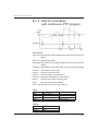
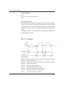
Ex. 4 : Electric orientation with continuous PTP program ...................................... SC10-98
Ex. 5 : Pause .......................................................................................................... SC10-99
Ex. 6 : Bank Select using nesting . ....................................................................... SC10-100
IN-6
COOL MUSCLE USER'S GUIDE
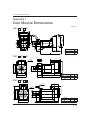
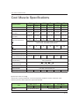
Appendix 1
Cool Muscle Dimensions . ............................................................................................AP1-102
Cool Muscle Specifications ..........................................................................................AP1-103
Input / Output Signal ....................................................................................................AP1-104
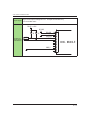
Interface Wiring Example .............................................................................................AP1-106
I/O Wiring Example ......................................................................................................AP1-107
Appendix 2
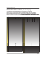
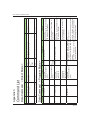
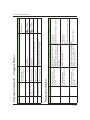
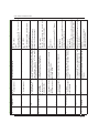
Parameter List ..............................................................................................................AP2-112
Parameter default values (For the shipping) ................................................................AP2-119
Appendix 3
Command List ..............................................................................................................AP3-120
Data Command <Direct Mode> <Program Mode> ......................................................AP3-120
Execution Command <Direct Mode>............................................................................AP3-121
Execution Command <Program Mode>........................................................................AP3-122
Program Mode .............................................................................................................AP3-122
Query ...........................................................................................................................AP3-124
Appendix 4
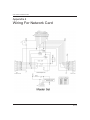
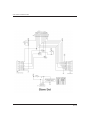
Wiring For Network Card . ............................................................................................AP4-125
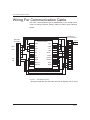
Wiring For Communication Cable ................................................................................AP4-127
Appendix 5
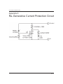
Re-Generative Current Protection Circuit ....................................................................AP5-128
Appendix 6
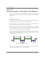
Comunication Time with Cool Muscle ..........................................................................AP6-129
Appendix 7
Position Mark Output . ..................................................................................................AP7-133
Origin Search ...............................................................................................................AP7-134
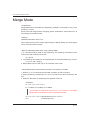
Merge Mode .................................................................................................................AP7-138
How to Adjust Gain . .....................................................................................................AP7-141
Appendix 8
Manual Terminology .....................................................................................................AP8-142
Revision History........................................................................................... RH-150
IN-7
COOL MUSCLE USER'S GUIDE
SECTION 1
ABOUT COOL MUSCLE
The Cool Muscle is a fully integrated closed loop vector drive servo
system. With an intelligent driver, a 32-bit RISC CPU, a magnetic
encoder and power management built onto the motor, the Cool
Muscle excels in performance, size and cost.
Supporting a wide variety of communication interfaces including
RS-232C, Pulse (CW/CCW and Step/Direction) and Analog Voltage, Cool Muscle can be used not only for new products but also
for replacement or upgrading the current system.
The Cool Muscle's high resolution encoder provides you the exceptional resolution of 50,000 pulse/rotation. Combined with vector
drive control, the Cool Muscle does not have a mis-step and is an
incredibly smooth and quiet motor.
CML (Cool Muscle Language) makes creation of motion programs
very simple and can be downloaded directly to the motor.
Cool Muscle Interface
Cool Muscle supports three different interfaces as Pulse, Analog
and Computer. Select an interface that will fit your application.
P
PULSE TYPE COOL MUSCLE
P type Cool Muscle can be a replacement for your current pulse
driven system and will remove problems as heat generation, misstep and etc, that are associated with an open loop stepper motor.
Further more, Cool Muscle can be a replacement for a Servo Motor and will provide a cost reduction and compactification.
P type Cool Muscle supports both CW/CCW and Pulse/Direction.
The type can be selected by the parameter K36.
SC1-8
COOL MUSCLE USER'S GUIDE
1: CW/CCW (K36=0)
Apply CW pulse to the input 1
Apply CCW pulse to the input 2
2: Step/Direction (K36=1)
Apply Step pulse to the input 1 (travel distance)
Apply Direction pulse to the input 2 (direction)
When the Direction pulse is high level, CW direction is set.
When the Direction pulse in low level, CCW direction is set.
Note
*The input voltage under DC+3V can not be recongnized as a pulse signal.
Please apply pulse signal from DC+5V to DC+24V.
*When using in the Step/Direction mode, please apply a Step pulse only when
Cool Muscle is stopping or a few msec after a Direction pulse is applied.
V
ANALOG TYPE COOL MUSCLE
V type Cool Muscle can vary speeds or positions in proportion to
an input analog voltage level. Set the max speeds or travel distance with ease by parameters. V type Cool Muscle is an ideal solution for constant feed system and valves.
Speed Control (K38=0)
The speed control in both CW and CCW direction in proportion to
an input analog voltage level. The max speed at the both direction
can be set by the parameter K40.
Position Control (K38=1)
The position control in proportion to an input analog voltage level,
referring to DC+4.8V as the max travel distance.
The max travel distance between DC+0.2V and DC+4.8V can be
set by the parameter K41.
Speed Control CW (K38=2)
The speed control in CW directon in proportion to an input analog
voltage level (from DC+0.2V to DC+4.8V). The max speed in CW
SC1-9
COOL MUSCLE USER'S GUIDE
direction can be set by the parameter K40.
Speed Control CCW (K38=3)
The speed control in CCW direction in proportion to an input analog voltage level (from DC+0.2V to DC+4.8V). The max speed in
CCW direction can be set by the parameter K40.
Note
The control types above drive the travel distance that is set by K40
or make the acceleration that is set by K41. If the analog voltage is
applied when supplying the power to Cool Muscle, it'll interfare the
applied input voltage.
Apply the analog voltage that adapts the motion before supplying
the power to Cool Muscle.
C
Computer Type
C-type (computer) is the most powerful Cool Muscle in three (3)
interfaces.
Pre-Program
If your application only requires repetitive motion, you can
preprogram the motor, eliminating the need for a controller.
Preloaded programs can be executed by a switch, PC or PLC.
Direct Command
If your application requires complicated motion or arbitrary motion,
you can send command
directly to the Cool Muscle via PC or embedded computers.
Network
The C type Cool Muscles can be daisy chained, providing you with
a simple and low cost network solution. There are different ways to
network the C type Cool Muscles to suit your needs.
SC1-10
COOL MUSCLE USER'S GUIDE
SECTION 2
WHEN YOU RECEIVE
COOL MUSCLE
When you receive a Cool Muscle package, please make sure that
you have all the components you ordered. You may then proceed
to the next step and connect the motor to your PC to make sure
that you have proper communications.
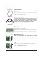
Cool Muscle Package
P
V
C
RS-232C Cable (YCable) is required
for all types of Cool
Muscle, to set parameters via RS232C from a PC.
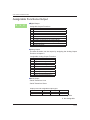
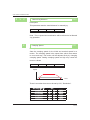
The components that you need to operate the Cool Muscle are listed in the green area in the table below. The components listed in
the pink area are the optional components for networking the Cool
Muscles.
Components/Interfaces
Pulse
Type
Analog
Type
Computer
Type
Cool Muscle Motor
Motor Cable
RS-232C Cable (Y-Cable)
24V Cool Muscle Power Supply
Manual CD*
Network Card(master set)
Network Card(slave set)
D-sub 9pin network straight cable
Male to Female
= included with the motor
= optional component
*"Cool Muscle User's Guide", "COOL WORKS LITE USER'S MANUAL", and CoolWorks Lite (Software) are included in this CD.
The CD shall be attached only at the first delivery.
SC2-11
COOL MUSCLE USER'S GUIDE
P
V
C
Components
Motor Cable
The Cool Muscle comes with one (1) motor cable. The standard
length of the motor cable is 40cm.
CM1C1-400S
RS-232C Cable (Y-Cable)
A RS-232C Cable is required to connect Cool Muscle to a PC via
RS-232C. This cable is required when downloading motor parameters and motion programs to Cool Muscle, or when you wish to
CM1C2-2000A
control a single motor via RS-232C serial communication.
In addition, a customer can make a RS-232C Cable.
Please refer to AP4-122.
Power Supply
A regulated DC+24V power supply.
Required power supplies may be available from your local distributor.
150W/240W power supply from Muscle is capable for peak current.
CMPS-XMUS-150-24
C
CM1DC1-MBS
Master Set
Daisy Chain Network Card
Those cards are for the Daisy Chain Network and can be mounted
on the back of the motor. The first motor from the upper controller
requires a Master Set and the other motors require the Slave Sets.
D-sub 9pin straight cable can be used between those network
cards.
Note:
Network cards can not be mounted on CM1-x-11S/L30 motors.
About wiring, please refer to AP4-121.
CM1DC1-SBS
Slave Set
SC2-12
COOL MUSCLE USER'S GUIDE
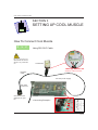
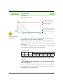
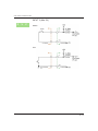
SECTION 3
SETTING UP COOL MUSCLE
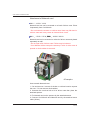
How To Connect Cool Muscle
P
V
C
Do not connect or
disconnect the motor
while it is powered
on.
Using RS-232C Cable
Cool Muscle
*����������������������������
Please pay attention to the
direction of the connector.
RS-232C
Cable
DC+24V power supply
RS-232C
Connector
Connect to a RS232C port on your
PC.
<Connecting Example>
-V
+V
SC3-13
COOL MUSCLE USER'S GUIDE
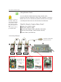
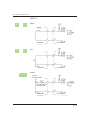
Using Network Cards
C
You can network multiple motors by using network cards.
Network Cards are required for Daisy Chain operation. Connect a
Master Set to an ID1 Cool Muscle (closest Cool Muscle to an upper
Instead of using a
RS-232C Cable, you
can use the network
card and the interface card to connect
the Cool Muscle to a
PC.
You need a D-sub 9
pin straight cable.
controller) and Slave Set to an ID2 and later Cool Muscles.
What Do I Need to Create a Daisy Chain?
Master Set (CM1DC1-MBS)
Slave Set (CM1DC1-SBS)
D-sub 9 pin Straight Cables (CM1DC1-SSC-1800)
CD+24V Power Supply (CMPS-XMUS-150/240)
Power Cable (Not Attached)
<Connecting Example>
Connect to a RS-232C
port on PC or PLC.
ID3 Motor
ID2 Motor
Slave Set
ID1 Motor
Master Set
Nuts
Slave Boad
Motor Cables
Nuts
Master Boad
Motor Cables
The Power Cable is
connected with Master Set.
SC3-14
COOL MUSCLE USER'S GUIDE
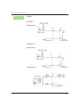
Attachment of Network card
CM1- * -11S30 / 11L30
Network card can not be mounted on a back of driver case. Place
it separately from Cool Muscle.
* Do not loosen the screws on a driver case. Nuts may fall down in
a driver case and it may cause an internal short circuit.
CM1- * -17S30 / 17L30�������
, CM1����� * -23S30 / 23L20
Network card can be mounted on a back of driver case and placed
separately as well.
* Do not open a lid of driver case. Failure may be induced.
* Cool Muscle will be exempt the warranty if a lid of driver case is
opened or whole sticker is removed.
<Example>
How to attach Network card
1. Cut and remove 4 corners of sticker on a driver board to expose
the nuts. * Do not remove whole sticker
2. Unscrew the nuts that lock a lid of driver case then place the
attached spacers.
3. Fix Network card on the spacers by the attached screws.
4. Connect Cool Muscle and Network card by the attached motor
cable (35mm).
SC3-15
COOL MUSCLE USER'S GUIDE
Connect Network Cards to Cool Muscle
About wiring, please refer to AP4-121.
Connect to a host computer via a straight cable
Master Set
+24V
E
Connect
Cool Muscle
via a motor cable
Connect to the next Cool Muscle via a straight cable
Connect to the previous Cool Muscle via a straight cable
Slave Set
+24V
E
Connect
Cool Muscle
via a motor cable
Connect to the next Cool Muscle via a straight cable
SC3-16
COOL MUSCLE USER'S GUIDE
Set Jumpers
The Jumper pins connection of Master Set and Slave Set is different. Please confirm that Jumpers are set properly on Network
Cards before connecting Network Cards to Cool Muscle.
Master Set
JP5
JP3
JP4
JP 3, JP 4, JP 5
• No require any pin connectJP2
ed
On Serial Daughter Card
JP 1, JP 2
• Leave the JP1&JP2 open
JP1
pin 1
pin 2
pin 3
JP1:Connect the pin 1&2
JP2:Connect the pin 2&3
Slave Set
JP4
JP 3, JP 4, JP 5
• Connect the pin 1&2 on each
JP
JP2
JP3
JP1
JP5
JP 1, JP 2
• Connect the pin 1&2 on the
JP1&JP2
• When power is supplied
through the terminal block on
the card, leave the JP1&JP2
open
SC3-17
COOL MUSCLE USER'S GUIDE
Communication with Cool Muscle
P
V
C
Connect Cool Muscle to your PC to make sure that the communication is established and the default parameters are set properly.
When you can not establish the communication, please refer to the
Trouble Shooting section that is included in the next page.
1. Connect the RS-232C Cable to Cool Muscle, PC and DC+24V
power supply, referring to the Section 3 "Setting Up Cool Muscle".
Please make sure that the power is turned off.
2. Start up Windows PC.
3. Start up Cool Works that is available on the CD provided with
Cool Muscle or can be downloaded from Muscle website at http://
www.coolmuscle.com.
Or Hyper Terminal on Windows is also available.
Please set up Hyper Terminal for Cool Muscle referring to the Section 5 "How to Set Up Hyper Terminal".
4. Power Cool Muscle on. As the drawing below, when motor information is displayed on a screen, the communication is established.
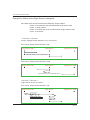
X.XX.X #XXXXX
5. Please check the default parameter.
Enter ?90 and press the Enter key
, all the user parameter shall
appear on the screen.
6. Turn off Cool Muscle and close Cool Works.
SC3-18
COOL MUSCLE USER'S GUIDE
Trouble Shooting of Communication
Nothing appears when Cool Muscle is powered on.
Is proper baud rate set when communicating with Hyper Terminal?
How to find the COM
port No. in Window XP
Open the Control panel,
click [Performance and
Maintenance] and then
[System].
Choose [Hardware] Tab
on the opened window
and then click [Device
Manager].
The available COM
ports are displayed in
the tree selection [Ports
(COM & LPT)] .
Once a baud rate is set on Hyper Terminal, it can not be changed.
When a wrong baud rate is set, please re-set a Hyper Terminal referring to as it follows.
Connection: Selected COM port ( ex: COM1)
Baud Rate: 38400
Data Bit: 8
Parity: N/A
Stop Bit: 1
Hand Shake: None
Is Cool Muscle powered on?
Please make sure that there is a servo rock on the motor shaft.
Please wait for a few minutes.
At the first communication, sometimes it takes a few minutes to receive a replying data from Cool Muscle.
Do you have multiple terminal applications running in the back
ground? Or do you have a software for PDAs or other programs
that occupy COM ports running? Make sure that these programs
are disable and not running in the background.
Nothing appears when ?90 is entered.
Parameters are not properly displayed. Turn the motor off and on.
If the motor responds with its version information, communication
is established.
Please check your PC setting including a key board.
SC3-19
COOL MUSCLE USER'S GUIDE
SECTION 4
INPUT AND OUTPUT
Pin Assignment and Layout
P
V
C
Cool Muscle has 4 inputs and 2 outputs that are user definable.
Each I/O port can be assigned multiple functions by setting motor
parameters using CML. Please refer to the SECTION 7.
1 2 3 4 5 6 7 8 9 1011 12
12
1
PIN Layout
PIN
1
Color
Name
Orange +24V DC IN
Function
Pulse
CW/CCW Step/Dir
Analog Computer
Motor Power
2
Black
GROUND 1
GND
3
Brown
INPUT 2-
Return For Pin9
4
Yellow
OUTPUT 2
Digital Output, Serial TX, Analog Output
5
Green
OUTPUT 1
Digital Output, Serial TX
6
Blue
INPUT 4
Digital Input, Analog Input
7
Purple
INPUT 3
Digital Input
8
Black
INPUT 1-
Return For Pin10
CW-
Step-
9
Gray
INPUT 2+
Digital Input, Pulse Counter, Serial RX
CCW+
Direction+
10
White
INPUT 1+
Digital Input, Pulse Counter, Serial RX
CW+
Step+
11
Black
GROUND 2
GND
12
Red
+5V DC OUT
5V Power Out (Max.10mA)
CCW-
Direction-
Serial
Serial
V+
Serial
Serial
V-
*About wiring example, please refer to Appendix 1.
SC4-20
COOL MUSCLE USER'S GUIDE
Assignable Functions-Input
P
V
C
Digital Input
Multiple functions can be assigned to a digital input port. By setting
the duration, the quick response and slow response signal can be
performed. Furthermore, functions can be assigned at the rising
and falling edges and target voltage level of either quick or slow response signals.
Assignable input functions at the target voltage level
#
0
1
2
3
4
6
7
8
9
Function
No Action
General Use
Origin Sensor Signal
Manual Feed CW
Manual Feed ���
CCW
CW Limit Sensor (Combined with Origin Sensor)
Emergency Stop
Full Stop (the same as ] ] )
CCW Limit Sensor (Combined with Origin Sensor)
Assignable input functions at the rising and falling edges
#
0
1
2
3
4
5
6
7
8
9
Function
No Action
Reset Alarm/Pause
Motor Free/Enable Motor
Reset Counter
Execute Next Step
Execute Previous Step
Execute Bank 1
Go Origin
Manual Jog CW
Manual Jog CCW
Example:
Input 4 is configured to be
K28=8000
K30=4000
K50=10
1. Assign Manual Jog of 10 pulses at the rising edge of quick
response signal
2. Assign Manual Feed CW at the target level of slow response
signal
SC4-21
COOL MUSCLE USER'S GUIDE
When quick response input signal is detected, motor will turn 10
pulses. When a slow response signal is detected, the motor turns
continuously for the duration of the signal.
Pulse Counter
P
Pulse signal can be applied to input 1 and 2 when using Pulse type
Cool Muscle.
CW/CCW
Step/Direction
P
V
C
V
C
Analog Input
Input 4 can be used for Analog input when using V or C type Cool
Muscle. Either speed or position can be cotrolled by Analog input
voltage.
Serial Input (Communication)
Input 1 (and 2 as well when networked) is used for serial
communication when using C type Cool Muscle.
Cool Muscle establishes its communication by automatic detection
of input 1 & 2 voltage level when powering on.
Please refer to the SC7-40.
Input ports and assignable input types
I/O
Input 1, 2
Input 3 (Max 5V)
Input 4 (Max 5V)
Digital In
O
O
O
Analog In
X
X
O
Pulse In
O
X
X
Serial In
O
X
X
O: Assignable
X: Not Assignable
SC4-22
COOL MUSCLE USER'S GUIDE
Assignable Functions-Output
P
V
C
Digital Output
Assignable Output Functions
#
0
1
2
3
4
5
6
7
8
9
Function
Commnad
In-Position
Alarm
General Use
General Use
Analog Output (Assignable only at Output 2)
In-Position at passing points in Merge Mode
Position Mark (K24 must be set separatelly)
During Motor Free
During Push Mode
Analog Output
The data as below can be output by assigning the Analog Output
Function at Output 2.
Assignable Analog Output Functions
#
0
1
2
3
4
5
6
7
8
9
Analog Output Function
Target Position
Target Position Magnified by 8
Current Position
Current Position Magnified by 8
Position Error
Position Error Magnified by 8
Current Speed
Current Speed Magnified by 8
Current Torque
Current Torque Magnified by 8
Serial Output
Serial Transmit to Host
Serial Transmit to Slave
Output ports and assignable output types
I/O
Output 1
Output 2
Digital Out
O
O
Analog Out
X
O
Serial Out
O
O
O: Assignable
X: Not Assignable
SC4-23
COOL MUSCLE USER'S GUIDE
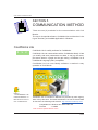
SECTION 5
COMMUNICATION METHOD
There are two (2) methods for the communication with Cool
Muscle.
The one is via special software, CoolWorks Lite and the other is via
Hyper Terminal, pre-installed application in Windows.
CoolWorks Lite
P
V
C
Refer to
"COOLWORKS LITE
USER'S MANUAL" in
Manual CD for how to
use CoolWorks Lite.
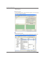
CoolWorks Lite is a utility software for CoolMuscle.
CoolWorks Lite can communicate with a CoolMuscle directly. It lets
you modify and save parameters and data. It can jog the motor,
plot motor data on a graph and do gain tuning. CoolWorks Lite is
CoolMuscle Language (CML) compatible.
CoolWorks Lite is a user-friendly software. It assists in easy
operation of Cool Muscle.
CoolWorks Lite is included in Manual CD provided by each agency
when it buys first time. The latest CoolWorks Lite can be downloaded
for free from the following web site also: http://www.musclecorp.com/
Compatible OS: Windows 98 / 2000 / ME / XP
File Size
: 2.35MB
*CWL would be updated without notice.
SC5-24
COOL MUSCLE USER'S GUIDE
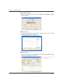
Main features
Terminal function
In the terminal window, data and bank programs can be set and
the status of motion monitored.
Motor browser function
In the motor browser window, the motor parameters are easily set.
SC5-25
COOL MUSCLE USER'S GUIDE
Jog motion function
In the Jog window, the motor can be rotated by dragging a slider
with the mouse.
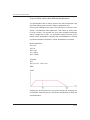
Graph function
In the graph window, the position, speed, torque, etc can be
displayed graphically in real time.
Tuning function
In the tuning window, controller gain can be easily tuned by step
response or frequency-response.
* This window will not work for
Ver 1.07 or before.
SC5-26
COOL MUSCLE USER'S GUIDE
How to Set Up Hyper Terminal
P
V
C
Hyper Terminal is a Communication Software, that is pre-installed
in Windows.
Communication is possible by command in text format, editing and
downloading of program file is possible as well.
The setting method of Hyper Terminal is explained.
Start Hyper Terminal and Set a communication method
1. Start
�����������������������
up Hyper Terminal
(Start / Program/ Accessory / Communication / Hyper Terminal)
2.����������������������
Form
���������������������
a New Connection
Enter a name in the “Connection Description” window.
Name :
Enter a simple name.
Ex): Cool Muscle
Icon :
Choose an Icon and click “OK”.
3.���������������������������
Set
��������������������������
a communication method
Click “OK” after selecting a
Com-Port that Cool Muscle is
connected to in the “Connect
To” window.
SC5-27
COOL MUSCLE USER'S GUIDE
4. Set the COM port as below and click “OK”.
How to find the COM
port No.
Open the Control panel,
click [Performance and
Maintenance] and then
[System].
Choose [Hardware] Tab
on the opened window
and then click [Device
Manager].
The available COM
ports are displayed in
the tree selection [Ports
(COM & LPT)] .
Baud Rate (bps) : 38400
Data bits
: 8
Parity
: None
Stop bits
: 1
Flow control
: None
5. Connect Cool Muscle, confirm the COM port that Cool Muscle is
connected then power on Cool Muscle.
The motor information will appear when the communication is established.
*It might take a few minutes to establish a communication with a PC when
Cool Muscle is connected for the first time.
Motor Information
SC5-28
COOL MUSCLE USER'S GUIDE
Operation method of Cool Muscle
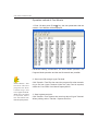
1. Enter ?90 then press "Enter " key, the user parameters that are
saved in Cool Muscle will be displayed.
Parameter setting, modification, the Direct Mode operation, the
Program Mode operation and the text file transfer are possible.
Click Transfer / Text
File then send the
program file when
transferring a file
from Hyper Terminal.
When the Line Feed
is required, select
the "Line Feed" from
Menu/Property/ASCII.
2. Send a text file through Hyper Terminal.
Click Transfer / Text File then send the program file when transferring a file from Hyper Terminal. When the Line Feed is required,
select the "Line Feed" from Menu/Property/ASCII.
3. Save log data and print.
Click Transfer / Text Capture then save log data of Hyper Terminal.
When printing, select Transfer / Capture and Print.
SC5-29
COOL MUSCLE USER'S GUIDE
Close Hyper Terminal
1. Save setting, exit Hyper Terminal and save the connection.
Power down Cool Muscle first then exit Hyper Terminal. Select File
/ Exit or click the “ X “ on top right hand side of the screen.
“Do you want to save the connection named “Cool Muscle”?”
screen will appear when exiting Hyper Terminal. Then click “Yes”
and save the connection setting.
2. Once the connection setting is saved, the saved file shall be
able to open directly from Start / All Programs / Accessories /
Communications / Hyper Terminal (folder) / Cool Muscle from next
time.
SC5-30
COOL MUSCLE USER'S GUIDE
SECTION 6
CML STRUCTURE
CML stands for���������������������
Cool Muscle Language, the ASCII commands only
for Cool Muscle.
Cool����������������
Muscle Language
P
V
C
CML (Cool Muscle Language) is a free method ASCII commands
that provide a simple creation of a motion program for single or
multi-axis systems. As CML can contain a motor ID, multiple Cool
Muscles can perform coordinated motion.
CML is composed as follows.
CML
Parameter
Command
Direct Mode
Data Command
Execution Command
Query
Program Mode
Data Command
Execution Command
Program Command
Enter “.ID” (Motor ID No.) after all parameter and command to
specify an ID number.
Data will be activated by entering “Enter
” after it.
SC6-31
COOL MUSCLE USER'S GUIDE
Parameters
P
V
C
By using CML, it is very simple to set parameters.
It is also very simple to change parameters to suit your specifications, although it is set to the default parameter when delivered.
Parameter Definition: K##.ID=Value
"K##" signifies a parameter number. ".ID" after K number signifies
an ID number. The Number represents the data to be assigned
to K##. A list of parameters and their corresponding numbers are
outlined in Section 6 "SETTING PARAMETERS" (Refer to the Appendix 2 "Parameter List").
Ex: K37.1=3 sets resolution as 1000ppr
Commands
Command can be used in different two modes.
Comprehension of the difference between those 2 modes is required for Cool Muscle operation.
C
P
V
C
Program Mode
Operation by the program that is downloaded to a Cool Muscle.
A program can be triggered by an execution command or an
input signal.
Direct Mode
Direct operation via PC to make an immediate action.
The communication using both Program / Direct mode with Cool
Muscle can be made from a terminal program as Cool Works or
Hyper Terminal.
SC6-32
COOL MUSCLE USER'S GUIDE
CML Structure
Command Structure & Rules
C
This section guides you to the Command Structure and Rules for
Cool Muscle program mode.
The basic structure of a CML command is:
P�����������
# . ID M = V a l u e
Period
Memory #
Modifier Command Value
Motor ID
Memory Number
Each command has a limited number for memory locations.
For example, Position, Speed and Acceleration can be stored in
25, 15 and 8 memory locations respectively. Specify the memory
location for the corresponding value.
Ex: P14.3=1000
The defined value 1000 is stored in position memory location 14 of
the ID3 motor. The value set by the parameter is absolute.
Motor ID
When operating multiple Cool Muscles, motor ID must be specified
in a program. The commands and parameters will be placed in the
memory locations of the specified motor. When Motor ID is left out,
it is assumed to be either motor 1 or the last ID value used.
SC6-33
COOL MUSCLE USER'S GUIDE
Modifier
The most common modifier is the "+" that is used with the P command. Adding "+" after the ID number of P data makes the value
relative. P14.3+ would command motor 3 to move relatively/incrementally 1000 pulses against Cool Muscle's current position.
(Refer to SC8-73.)
Value
All the value that is defined by commands shall be absolute. All values as A, S, P and T shall be set before making a program.
Spaces
Spaces should not be used in a command line.
Upper or lower case?
All the commands in CML program files can be either upper or
lower case letters.
SC6-34
COOL MUSCLE USER'S GUIDE
CML File Structure -�������������
Program
������������
Mode
C
CML files consist of 2 different parts. The first part defines memory
contents as Positions, Speeds, Accelerations and Timers, and the
second part defines program.
Example:
P1.1=30000
P2.1=250000
S1.1=500
A1.1=200
.
.
B1.1
S1.1, A2.1, P1.1
B3.1
S1.1, A2.1, P3.1
.
.
Data Command
Program Command
Memory Contents
Position, Speed, Acceleration and Timer definition takes the form
of:
P#.ID=Value ( #=1 25 memories )
S#.ID=Value ( #=1 15 memories )
A#.ID=Value ( #=1 8 memories )
T#.ID=Value ( #=1 7 memories )
CML Program Banks
All programs shall be made by CML motion commands and stored
in the specified bank memory. A program is defined as it follows:
B#.1
B# specifies the program bank number (up to 30 banks) and commands that make up the contents of program bank. Each program
bank can be regarded as an object. Program Bank may contain up
to 500 steps. CML commands and structures are outlined in the
CML Command List.
SC6-35
COOL MUSCLE USER'S GUIDE
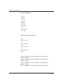
CML Program File Example
C
K26.1=1111 / Set Input Logic
K49.1=15 / Set the Speed for Manual Feed
K58.1=500 / Set Software Limit CW
K59.1=-500 / Set Software Limit CCW
P1.1=1000 / Definition for Position Memory 1
P2.1=2000 / Definition for Position Memory 2
P3.1=4000 / Definition for Position Memory 3
S1.1=200 / Definition for Speed Memory 1
S2.1=500 / Definition for Speed Memory 2
A1.1=200 / Definition for Acceleration Memory 1
A2.1=100 / Definition for Acceleration Memory 2
B1.1 / Start of The Content of Bank 1
C2.1 / Call The Beginning of Bank 2
C3.1 / Call The Beginning of Bank 3
B2.1 / Start of The Content of Bank 2
S1.1, A1.1, P1.1 / Motion to P1 with A1 and S1
S2.1, A2.1, P2.1 / Motion to P2 with A2 and S2
B3.1 / Start of The Content of Bank 3
S1.1, A2.1, P3.1 / Motion to P3 with A2 and S1
(Please refer to SECTION 9 "CML Program Basic Example" for
more detailed information.)
SC6-36
COOL MUSCLE USER'S GUIDE
CML File Structure -������������
Direct
�����������
Mode
P
V
C
Motor can be directly operated by commands in Direct Mode.
This mode is useful for debugging or voluntary movement.
Direct mode is available in all types of Cool Muscle.
Direct Mode Structure:
S.ID=Value
A.ID=Value
P.ID=Value
^.ID ( Execute )
In Program Mode, you need to define position, speed, acceleration
and timer. In Direct Mode, you can directly operate Cool Muscle by
entering motion profile.
Example:
S.1=250
A.1=100
P.1=10000
^.1
SC6-37
COOL MUSCLE USER'S GUIDE
CML File / Command Downloading
P
V
C
There are a number of ways to use CML to set parameters, define
motions, create programs, download program, execute programs
and operate Cool Muscle.
CoolWorks Lite is a free software from Muscle Corporation designed to work with CML. Hyper Terminal is also available that is
To save the file by text
format (.txt) is recomm e n de d to t r ans fe r
the file directly from
Cool Works or Hyper
Te r m i n a l. I t i s a l s o
recommended to edit
the content of the program.
usually included with your Windows installation disk.
To change parameters, execute program banks, operate Cool
Muscle in the Direct Mode can be executed by commands from
Hyper Terminal or Cool Works via RS-232C communication.
Creating and Editing Program Banks
It is recommended to use editor programs such as Microsoft Word
to creat and edit Program Bank files.
You can download Program Bank files via a terminal program by
importing text files. You can also download parameters in the same
method.
When changing parameters, only specified parameter shall be
changed. It will not affect unspecified parameter.
When writing Program Bank, it must begin with "B1.1". Even when
changing a part of Program Bank or whole content of another
Bank, it must begin with "B1.1".
Please enter a "$" and "Enter
" at the end of the CML program
to save the data in Cool Muscle. When changing only parameter,
the "$" does not need to be sent.
The limit of the number for over-writing each data is 100000 times.
SC6-38
COOL MUSCLE USER'S GUIDE
SECTION 7
SETTING PARAMETERS
This section guides you to the details of parameters and instruction
for setting. Please refer to Appendix 2 for Parameter List.
CML
Parameter
Command
Direct Mode
Data Command
Execution Command
Query
Program Mode
Data Command
Execution Command
Program Command
Before Setting Parameters
To set parameters on Cool Muscle, you need to connect Cool Muscle via RS-232C cable (CM1C2-2000A) or network card. You can
set parameters on multiple Cool Muscles when they are networked
via network cables.
P
V
C
RS-232C Cable
Connect the Cool Muscle (refer to SECTION 3 "SETTING UP
COOL MUSCLE"). Start up Cool Works or the Hyper Terminal and
turn Cool Muscle on. Make sure that there is communication established between Cool Muscle and your PC.
C
Network Cable
Connect Cool Muscles ( refer to SECTION 3" ). Start up CoolWorks Lite or the Hyper Terminal and turn Cool Muscle on. Each
Cool Muscle is automatically given a motor ID. Make sure that
communication is established between Cool Muscles and your
PC ( refer to SECTION 5 ). The motor information from the daisychained Cool Muscles will be displayed.
SC7-39
COOL MUSCLE USER'S GUIDE
C
Automatic Identification
Cool Muscle executes an upper and lower communication status
confirmation when power is supplied.
Please note that as it
has been exemplified
o n r i ght- han d s i de,
Cool Muscle starts the
Communication Mode
automatically by the
setting of Input1.
When power on
Input1 On
Communication Mode
Accept only command
Input2 On
Communication Mode to a Daisy-Chained
Slave(lower) Cool Muscle.
When Input1 and Input2 are on, Cool Muscle goes into
Communication and Daisy-Chain Mode.
Therefore Input1, Output1 and Input2, Output2 shall be kept for
Communication.
Only the last Cool Muscle in Daisy Chain recognize it the last end
because Input2 shall stay off.
Therefore the Output2 of the last Cool Muscle can be used.
When operating by pulse signal (using input 1 & 2 for pulse signal),
do not apply high voltage when powering on.
*External devices such as a sensor, are recommended to be
connected to input 3 or 4.
Cool Muscle may establish communication by detecting high level
signal when powering on, when external devices are connected to
input 1 or 2.
SC7-40
COOL MUSCLE USER'S GUIDE
Parameter Structure
P
V
C
The parameter of all types of Cool Muscle ( P, V, C ) can be set
from PC. Each parameter is assigned specified functions. ( Refer
to Appendix 2 "Parameter List" ).
The structure of parameter is:
K##.ID = Value
Example:
K50.1=15
Manual jog travel distance of the ID1 motor is set to 15 pulses.
Please put ".ID" (Motor ID) after all parameters to specify Cool
Muscle of the object.
It becomes effective by inputting "Enter
" after each data.
SC7-41
COOL MUSCLE USER'S GUIDE
Parameter
P
V
C
Baud Rate
K20
Description
Set the baud rate to communicate with an upper controller.
Make sure that the same baud rate is set on the upper controller
side.
#
0
1
2
3
Baud Rate
38.4 Kbps
9.6 Kbps
19.2 Kbps
57.6 Kbps
Example:
K20.1=0
Set baud rate to 38.4Kbps.
K20.1=0 ( 38.4Kbps ) is the Cool Muscle's default value.
C
Open Loop Vector Angle
K21
Description
By the combination of K21 and K22, Cool Muscle goes into an
open loop mode when there is no position command during the set
time by K22 after in-positioning.
If Cool Muscle moves off the set angle by K21, Cool Muscle goes
into a closed loop again and back to the previous target position.
#
0
1-36
Rate
Full Closed Loop
Unit x 0.1 degree
Example:
K21.1=10
Set the vector angle to 1 degree.
If Cool Muscle moves off 1 degree, it goes into a closed loop again
and back to the previous target position.
SC7-42
COOL MUSCLE USER'S GUIDE
C
Trigger Timing for Open Loop Mode
K22
Description
This parameter lets you set a trigger timing for an open loop.
This trigger timing is a time delay between in-position signal and
the moment when Cool Muscle goes into an open loop.
Min
10
Max
1000
Default
200
Unit
msec
Example:
K22.1=500
Cool Muscle goes into an open loop mode when there is no position command for 500 msec after in-positioning.
P
V
C
Status Report
K23
Description
Set the method of status report from Cool Muscle.
The registrable number is from 0 to 31 as shown below.
The number can be combined by addition.
0: Polling
1: In-position and Alarm
2: Report when input status changes
4: Report when output status changes
7: Combination of 1, 2, and 4
8: No Local Echo (No return input signal)
16: Display Error Messages
SC7-43
COOL MUSCLE USER'S GUIDE
Message
Meaning
error : Out Of Range !!
Unsettable values for K parameters
error : syntax error !!
Description in Program Bank is wrong
error : too many steps !!
Steps in Banks are more than 500
[End Bank]
Program Banks are ended properly
Change Baud Rate ??
×××Kbps (Y/N)
When Baud Rate is changed by K20 or K65
error : CW Limit !!
CW Limit Sensor ON
error : CCW Limit !!
CCW Limit Sensor ON
Example:
K23.1=0
Cool Muscle replies only against the queries that are sent to Cool
Muscle. The local echo shall be displayed as well.
K23.1=13 (1+4+8)
Cool Muscle automatically reports the status when Inpositioning,
Alarm and output status changes.
The local echo shall not be displayed.Description
P
V
C
Position Mark
K24
Description
Turn output on/off at regular intervals with pulses (Set K34=7).
The signal wave pattern shall be as below.
Turn the output on at the first half of the set pulse then off at the
last half of the set pulse by K24. (Refer to Appendix7.)
Min
10
Max
32767
Default
1000
Unit
pulses
High
Low
More than
2msec
More than
2msec
Output On
Output Off
K24 Set Pulse
SC7-44
COOL MUSCLE USER'S GUIDE
P
V
C
Time Offset for Slow Response Signal
K25
Description
This parameter sets the time delay to create two sets of signals,
quick and slow response signal. Slow response signal is a vertual
signal that is made by software, the specified time delay after the
real signal to cover the paucity of input numbers.
If the signal is completed within the set time delay period, it is only
recognized as a quick response signal but not as a slow response
signal.
Min
1111
Max
9999
Default
3333
Unit
0.1sec
Input Order is In 4, 3, 2, 1. Each digit must be set individually.
Example: K25.1=6332
Input 1 = 0.2sec
Input 2 = 0.3sec
Input 3 = 0.3sec
Input 4 = 0.6sec
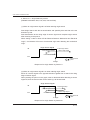
Quick and Slow response time off set
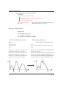
A quick response signal starts when it hits the high level. A slow response signal starts after the time offset set by the parameter K25.
When K25.1=2222, the slow resoponse signal rises and falls 0.2sec
after the quick response signal.
High
Original
Signal
Low
Quick
Response
Slow
Response
0.2 sec
SC7-45
COOL MUSCLE USER'S GUIDE
Quick and Slow response event triggers
Events (functions) can be assigned to the rising and falling edges
and the target voltage of a quick and slow response signals.
Quick Response
Target Voltage Level
Rising Edge
Falling Edge
Slow Response
Target Voltage Level
Rising Edge
Falling Edge
0.2 sec
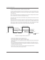
Short Signal
When a signal is completed within the offset time, only a quick response signal is recognized.
High
Low
Original
Signal
Quick Response
Target Voltage Level
Rising Edge
Falling Edge
*Slow response is
not recognised.
Slow Response
Target Voltage Level
0.2 sec
SC7-46
COOL MUSCLE USER'S GUIDE
P
V
C
Input Logic
K26
Description
This parameter sets the input logic.
Min
0000
Max
1111
Default
0000
Descriptions
0: Active by low level signal
1: Active by high level signal
Input Order is In4, 3, 2, 1. Each digit must be set individually.
Please set the input
logic referring to the
output logic at the
upper controller side.
Example: K26.1=1010
Input 1 = Normally Open
Input 2 = Normally Closed
Input 3 = Normally Open
Input 4 = Normally Closed
SC7-47
COOL MUSCLE USER'S GUIDE
P
V
C
Input Functions at the Quick Response Target Voltage
K27
Input Functions at the Slow Response Target Voltage
K30
Description
These parameters assign functions performed for the duration of a
When input logic is
active low, the target
voltage level is less
than DC+0.8V(7mA)
and when active high, it is from
DC+3V to DC+5V.
The shortest signal
shall be 10msec.
signal. Assignable functions are listed below. (Refer to SC7-44)
Assignable Functions for the Target Voltage Level
#
0
1
2
Functions
No Action
General Use
Origin Sensor* (K27)
-(K30)
3
Manual Feed CW
Motor runs in a CW direction for the
duration of the signal
Manual Feed CCW
Motor runs in a CCW direction for the
duration of the signal
--CW Limit Sensor with Usually used for a CW Limit sensor. But
Origin Sensor
only after an origin search command, the
sensor shall work as an origin sensor
Emergency Stop
Emergeny Stop (stop by Max deceleration)
Full Stop
Stop as ] ]
CCW Limit Sensor with Usually used for a CCW Limit sensor. But
Origin Sensor
only after an origin search command, the
sensor shall work as an origin sensor
4
When a function is
assigned to input 1
or 2, a signal from a
PC might activate the
function. Do not assign any function to
input 1 and 2 when
using in communication mode with PC.
Description
No Anction
Typically Used for the I command
The signal from Origin Sensor (K27)
-(K30)
5
6
7
8
9
*Please refer to Appendix 7 for about Origin Sensor.
Min
0000
0000
Max
9999
9999
Default
0000 (K27)
0000 (K30)
Input Order is In4, 3, 2, 1. Each digit must be set individually.
When positioning
to an origin after
stopping by a limit
sensor (function 6 or
9), position deviation
may occur.
The position deviation
will be canceled
by Enable Motor
command “ ( “ after
limit sensor is on.
Example: K27.1=1243
Input 1 = Manual Feed CW
Input 2 = Manual Feed CCW
Input 3 = Origin Sensor
Input 4 = General Use
* Origin sensor has a prior to the other function in Ver.2.25 and
Ver2.35. The priority in -Ver.2.24, -Ver2.33 is in order of Input 4, 3, 2,
1. (AP7-130 for detail)
SC7-48
COOL MUSCLE USER'S GUIDE
P
V
C
By setting K36=2, the
execution of bank 2
or 3 can be assigned
to either rising or falling edge of a signal.
Input Functions at the Quick Response Rising Edge
K28
Input Functions at the Quick Response Falling Edge
K29
Input Functions at the Slow Response Rising Edge
K31
Input Functions at the Slow Response Falling Edge
K32
Description
These parameters assign functions performed at the edge of a
signal. Functions or events should be assigned to event triggers in
such a way as to make sense.
For example, it may create undesirable movements if you assign
Motor Free to the rising edge of a quick response signal and Go
Origin to the duration of a slow response signal. With this input
function assignment, when the motor is commanded to go back
to origin, as it goes into a free state at the rising edge of a quick
response signal, it will not be able to go back to origin. (Refer to
SC7-44)
Assignable Functions at the rising and falling edges of an input signal Functions with <> indicate only for the falling edge.
#
0
1
2
3
4
5
6
7
8
9
Function
No Action
Reset Alarm/Pause
Description
Reset Alarm:
When Alarm is on, it resets the alarm
Pause:
Pause a motor. Send a start signal to resume a
motion
Motor Free
Make a motor go into a motor free state
<Enable Motor>
<Enable a motor from a motor free state>
Counter Reset
Make the current position 0
Execute Next Line
Execute the next line in a Bank
Execute Previous Line Execute the previous line in a Bank
Availability depends on a program
Execute Bank 1
Go Origin
Manual Jog CW
Motor runs in a CW direction.
/Execute Bank 2
The other values shall be set by K43, 49 and 50.
When K36=2, execute Bank 2.
Manual Jog CCW
Motor runs in a CCW direction
/Execute Bank 3
The other values shall be set by K43, 49 and 50.
When K36=2, execute Bank 3.
The parameter List in the Appendix 2 shall be referred to.
SC7-49
COOL MUSCLE USER'S GUIDE
Example: K28.1=7612
Input 1 = Motor Free
Input 2 = Reset Alarm/Pause
Input 3 = Execute Bank 1
Input 4 = Go Origin
P
V
C
Output Logic
K33
Description
This parameter sets the output logic.
Min
00
Max
11
Default
11
Description
0: Normally Open
1: Normally Closed
Output Order is Out2, 1. Each digit must be set individually.
Example: K33.1=01
Input 1 = Normally Closed
Input 2 = Normally Open
SC7-50
COOL MUSCLE USER'S GUIDE
P
V
C
Output Functions
K34
Description
This parameter assigns a function to an output. Assignable functions are shown in the table below.
#
0
1
Function
Command
In-Position
2
3
4
5
7
Alarm
General Use
General Use
Analog Out
(must be assigned in the
second digit)
Output In-Posiiton Signal in
Merge Mode
Position Mark
8
9
Motor Free
Push Mode
6
Min
00
Max
99
Description
In-Position signal when the motor
reaches the target position
O Command / F Command
O Command / F Command
Outputs analog waves for monitoring.
Select a type of information by
parameter K35
Outputs a signal at the passing points in
Merge Mode ( K73 shall be set )
Outputs a signal at certain intervals.
K24 shall be set for its intervals.
Outputs a signal during motor free
Outputs a signal during the push mode
Default
21
Output Order is Out2,1. Each digit must be set indivisually.
Example: K34.1=51
Input 1 = In-Position
Input 2 = Analog Out
SC7-51
COOL MUSCLE USER'S GUIDE
P
V
C
Analog Output
K35
Description
This parameter sets an analog output type that you can monitor
with an oscilloscope. Make sure that you select Analog Out by the
parameter K34. The range of analog output is 0-5V. 2.5V is the
baseline. The overall value is output but the analog output is displayed in the set range(0-5V).
*This function is assignable only to Output 2
+1024 pulses
0 pulses
-1024 pulses
#
0
1
2
3
4
5
6
7
8
Analog Output Types
Target Position
Target Position magnified by 8
Current Position
Current Position magnified by 8
Position Error
Position Error magnified by 8
Current Velocity
Current Veocity magnified by 8
Current Torque
9
Current Torque magnified by 8
Min
00
Max
90
Unit
±1024 pulses/±2.5V
±128 pulses/±2.5V
±1024 pulses/±2.5V
±128 pulses/±2.5V
±1024 pulses/±2.5V
±128 pulses/±2.5V
±2400 rpm/±2.5V
±300 rpm/±2.5V
±9.3 kgfcm/±2.5V(23L20)
±5.1 kgfcm/±2.5V(17L30)
±1.16 kgfcm/±2.5V(23L20)
±0.64 kgfcm/±2.5V(17L30)
Default
30
Output Order is Out2, 1. Each digit must be set individually.
*The first digit is 0 without fail.
SC7-52
COOL MUSCLE USER'S GUIDE
P
C
Pulse Type
K36
Description
This parameter sets Pulse Type Cool Muscle to either CW/CCW or
Step/Direction.
#
0
1
2
Type
CW / CCW
Step / Direction
Changes the assignable input functions, Manual
Jog CW and CCW to Execute Bank 2 and 3.
K28-K32 shall be referred to. (C type Only)
If you are using C type Cool Muscle, this parameter allows you to
assign Execute Bank 2 and 3 to rising and falling edges of input
signals when K36=2.
P
V
C
Motor Resolution
K37
Description
This parameter sets the motor's resolution (pulse/rotation) and the
speed unit that is used by the speed command (S). The value 0-10
Please set the speed
unit 100pps in normal operation. When
using the extremely
slow speed, please
set it to 10pps speed
unit.
Do not change the
resolution when
motor is running.
and 40-50 sets the speed unit to 100pps, and 20-30 and 70-80
sets to 10pps.
Speed Unit 100pps
#
Resolution
#
0
200
40
1
400
41
2
500
42
3
1000
43
4
2000
44
5
2500
45
6
5000
46
7
10000
47
8
25000
48
9
49
10 50000
50
Resolution
300
400
600
800
1200
1500
3000
4000
6000
8000
12000
Speed Unit 10pps
#
Resolution #
20 200
60
21 400
61
22 500
62
23 1000
63
24 2000
64
25 2500
65
26 5000
66
27 10000
67
28 25000
68
29
69
30 50000
70
Resolution
300
400
600
800
1200
1500
3000
4000
6000
8000
12000
Incremental movement can not be executed when K37 value is
over 40.
SC7-53
COOL MUSCLE USER'S GUIDE
The max values for each resolution are as below.
#
0, 20
1, 21
2, 22
3, 23
4, 24
5, 25
6, 26
7, 27
8, 28
9, 29
10, 30
Max
8,589,934
17,179,869
21,474,836
42,949,672
85,899,345
107,374,182
214,748,364
429,496,729
999,999,999
N/A
999,999,999
#
40, 60
41, 61
42, 62
43, 63
44, 64
45, 65
46, 66
47, 67
48, 68
49, 69
50, 70
Max
13,421,772
17,895,697
26,843,545
35,791,394
53,687,091
67,108,863
134,217,727
178,956,970
268,435,455
357,913,941
536,870,911
Continious mode (P=1000000000) is still available in any resolution.
Cool Muscle's internal counter has a limitation as shown in the
above table and the operation within this limitation is recommended.
As exceptions, Cool Muscle can be operated over Max. position
value only by continuous position command (P=1000000000) or
incremetal command.
However, when Pausing or Stopping over Max.position value by
continuous or incremental positioning, the internal counter value
becomes over limitation and a polar (plus or minus) of current position
will be switched in the internal counter then Cool Muscle will be
operated from a polar switched current position to a set target position.
Therefore please do not operate over Max. position value in general
use. When operation over Max. position value is required for an
application such as only one direction operation, please execute
Counter Reset" by command or input functions
V
C
Analog Type
K38
Description
This parameter sets V-type Cool Muscle to either speed or position
control.
#
0
1
2
3
Object for Control
Speed Control ( CW/CCW )
Position Control ( CW/CCW )
Speed Control ( CW )
Speed Control ( CCW )
SC7-54
COOL MUSCLE USER'S GUIDE
V
C
Voltage Filter Gain
K39
Description
Cut-off frequency for Low Pass Fliter for AD converter.
Min
0
Max
1024
Default
128
Unit
5 [rad/sec]
���������
Unit: 5000 [times/sec] / 1024=5 [rad/sec]
V
C
Analog Speed Range
K40
Description
This parameter sets the speed at 4.8V for speed type analog Cool
Muscle. Increase an analog input voltage up to 4.8V to increase the
speed ( K38 shall be set separately ).
When K38=0, K40=2000
The speed will increase up to 2000rpm in CW direction by increasing
an analog input voltage from 2.6V to 4.8V. The speed will increase up
to 2000rpm in CCW direction by decreasing an analog input voltage
from 2.4V to 0.2V. Note that an area between 2.4V and 2.6V is a dead
zone within which no motion will occur.
When K38=2, K40=1000
The speed will increase up to 1000rpm in CW direction by increasing
an analog input voltage from 0.2V to 4.8V.
When K38=3, K40=1200
The speed will increase up to 1200rpm in CCW direction by increasing
an analog input voltage from 0.2V to 4.8V.
Min
200
Max
4000
Default
200
Unit
rpm
Note if supply the power to Cool Muscle applying an analog voltage,
Cool Muscle may start running following the applied analog voltage.
(K64 for the reference)
SC7-55
COOL MUSCLE USER'S GUIDE
V
C
Analog Distance Range
K41
Description
Cool Muscle V-Type changes position in proportion to the input voltage
from DC+0.2V to DC+4.8V. This parameter sets the maximum travel
distance at 4.8V ( K38 shall be set separatety ).
Min
-32767
Max
32767
Default
2000
Unit
pulses
When K38=1, K41=4000
The distance will control from 0 to 4000pulses by increasing an analog
input voltage from 0.2V to 4.8V. (K64 for the reference)
P
V
C
Speed for Origin Search
K42
Description
This parameter sets the speed when the motor goes back to an origin.
Min
1
P
V
C
Max
5000
Default
10
Unit
100pps
Acceleration for Origin Search
K43
Description
This parameter sets the acceleration used when the motor
searches origin. This acceleration is also used for manual feed.
Min
1
C
Max
5000
Default
100
Unit
Kpps2
Deceleration Ratio
K44
Description
This parameter sets the deceleration ratio based on acceleration
(defined by the "A" command ). The deceleration can be set as a
percentage of acceleration. Note that the percentage set by this
parameter willl apply to all deceleration in CML program files.
(Refer to SECTION 9)
Min
10
Max
500
Default
100
Unit
%
SC7-56
COOL MUSCLE USER'S GUIDE
P
V
C
Origin Search Direction
K45
Description
This parameter sets the direction for the origin search.
#
0 ( Default )
1
Direction
CW
CCW
If origin search command is executed at the point where the origin
sensor is on, the motor will move to the opposite direction until it
detects the edge of the origin sensor signal.
Origin Search
Direction
Origin Search
P
V
C
OFF
ON
If origin search command is executed
at this point, motor will move in the
opposite directin to move out of the
origin sensor until it detects the edge of
the signal.
Origin Search Method
K46
Description
This parameter specifies the method for the Origin Search. Origin
Please set the proper
input logic for Origin
Sensor. If it is not set
properly, motor recognizes as if sensor
is on when it is off.
can be determined using hard stop/bumper or an origin sensor. It
also specifes if motor starts origin search automatically when the
power is supplied to the motor.
#
0 ( Default )
1
2
3
Method
Stopper / Bumper
Stopper / Bumper, Automatically when powered on
Origin Sensor
Origin Sensor, Automatically when powered on
The following related parameters shall be set separately
Stopper
K42 Origin search speed
K��
43 Origin search acceleration
K45 Origin search direction
Current level for Origin Search
K��
47
by Stopper
Origin Sensor
K42 Origin search speed
K��
43 Origin search acceleration
K27 Origin sensor
SC7-57
COOL MUSCLE USER'S GUIDE
P
V
C
When the acceleration for the origin
search is set too
high, the current level goes up to the set
level by K47. Please
reduce the K43 value
in such a case.
P
V
C
Current Level for Origin Search by Stopper
K47
Description
Sets the current level at which the motor will determine that the
origin position has been reached during a stopper/bumper origin
search routine. It is set by percentage.
Note ; The max, value 100 is the 80% of the motor's peak current.
Min
10
Max
100
Default
30
Unit
% of the peak current
Off Set Distance between Mechanical Origin
And Electrical Origin
K48
Description
This parameter sets the offset distance between the mechanical
and electrical origins. The parameter is for the motor to find the
mechanical origin then automatically go to the electrical origin
( starting point ). The mechanical origin and electrical origin are the
same by the default parameter K48=0. The speed for moving from
the mechanical origin to electrical origin is the same as the speed
for the origin search.
Min
-32767
P
V
C
Max
32767
Default
0
Unit
x100 pulses
Manual Feed Speed
K49
Description
This parameter sets the rotational speed for manual jog.
Min
1
Max
5000
Default
10
Unit
100 pps
SC7-58
COOL MUSCLE USER'S GUIDE
P
V
C
Manual Jog Distance
K50
Description
This parameter sets the travel distance for manual jog.
Min
1
Max
100
Default
10
Unit
1 pulses
Note ; The no speed and acceleration will be referred to for Manual
Jog operation.
C
Creeping Speed
K51
Description
Sets the creeping speed for the initial and terminal speed for a
motion. The creeping speed is the speed from which motor starts
to move and stop. The motion will be adjusted finely by changing
creeping speed. Setting creeping speed too high may cause the
motor to vibrate.
Min
1
Max
100
Default
10
Unit
100 pps
Speed
P1
P2
Time
There is a number that can not be set by K37, “Resolution”.
K51 Settable Value
more than 2
more than 5
more than 10
more than 2
more than 2
more than 5
K37
7
8
10
48
49
50
27
28
30
68
69
70
Resolution
10000
25000
50000
6000
8000
12000
SC7-59
COOL MUSCLE USER'S GUIDE
P
V
C
K52
Position P Gain
<Description>
Setting Position P Gain.
KPp
The stable gain mode
When an even number is applied
Stable gain is applied
KPp/2
KPp/3
The variable gain mode
Position
P Gain
When an odd number is applied
768 rpm
1536 rpm
2304 rpm
High speed/low speed gain
adjustment
Refer to "The gain
adjustment steps" in
the Appendix 7.
For variable gain mode, setting gain value is applied to slow speed operation.
Speed above 768rpm, the gain value reduces inverse proportion.
When speed is 2304rpm, the gain value will be one-third of setting value.
When K52=101, the gain value will be 100 during the slow speed
(up to 768rpm)
operation, and then the gain value reduces inverse
KSp+50
proportion and when speed is 3000 rpm, the gain value will be 25.
* To switch stable gain mode and variable gain mode, it is switched
KSp
by configuring an even number or an odd number.
Speed
P Gain
<Setting value>
Min
0
300rpm
Max
300
Default
50
11L
70
Default3000rpm
for the shipping
11S
70
17L
151
17S
50
23L
151
23S
50
* �������������������������������������������������������������������
Each type of Cool Muscle has different default gain values for the
shipping.
9
* ���������������������������������������������������������������
When applying value outside range or it can accept, the values
8
will not be changed.
When Cool Muscle other than Ver.2.25 and Ver.2.35 are handled,
5 the values will be set back to default values above that are not to
the default values for the shipping.
Speed
I Gain
30rpm
54rpm
3000rpm
SC7-60
KPp
KPp/2
KPp/3
COOL MUSCLE USER'S
GUIDE
Position
P Gain
P
V
768 rpm
C
1536 rpm
Speed P Gain
2304 rpm
K53
<Description>
Setting Speed P Gain
The variable gain mode
When an odd number is applied
KSp+50
High speed/low speed gain
adjustment
KSp
The stable gain mode
When an even number is applied
Speed
P Gain
Stable gain is applied
300rpm
Refer to "The gain
adjustment steps" in
the Appendix 7.
9
8
5
3000rpm
For variable gain mode, this gain setting value applies to when the
speed is 0 rpm.
When Speed is between 0rpm and 300rpm, Speed P gain value
increases in proportion.
The conclusive gain value is setting gain value plus 50.
* To switch stable gain mode and variable gain mode, it is switched
by configuring an even number or an odd number.
<Setting value>
Speed
I Gain
Min
Max
Default
0 30rpm512
54rpm
250
Default for the shipping
11L
150
11S
17L
150 3000rpm
150
17S
200
23L
201
23S
200
* �������������������������������������������������������������������
Each type of Cool Muscle has different default gain values for the
shipping.
* ���������������������������������������������������������������
When applying value outside range or it can accept, the values
will not be changed.
When Cool Muscle other than Ver.2.25 and Ver.2.35 are handled,
the values will be set back to default values above that are not to
the default values for the shipping.
SC7-61
KSp+50
KSp
COOL MUSCLE USER'S GUIDE
Speed
P Gain
P
V
C
300rpm
Speed
3000rpm
I Gain
K54
<Description>
Setting Speed I Gain
The stable gain mode
9
When an even number is applied
8
Stable gain is applied
5
The variable gain mode
When an odd number is applied
Speed
I Gain
High speed/low speed gain
54rpm
30rpm
Refer to "The gain
adjustment steps" in
the Appendix 7.
3000rpm adjustment
For variable gain mode, the speed that a set value and speed I
gain become 0 is in the relation of proportion.
When K54=5, Speed I gain will be 0 after speed is getting over
30rpm. When K54=9, Speed I gain will be 0 after speed is getting
over 54rpm
* To switch stable gain mode and variable gain mode, it is switched
by configuring an even number or an odd number.
< Setting value>
Min
Max
Default
0
10
2
Default for the shipping
11L
1
11S
1
17L
5
17S
5
23L
4
23S
5
* �������������������������������������������������������������������
Each type of Cool Muscle has different default gain values for the
shipping.
* ���������������������������������������������������������������
When applying value outside range or it can accept, the values
will not be changed.
When Cool Muscle other than Ver.2.25 and Ver.2.35 are handled,
the values will be set back to default values above that are not to
the default values for the shipping.
SC7-62
COOL MUSCLE USER'S GUIDE
P
V
C
In-positon signal is
different from completion and is sent
out when a motor
reaches within the
set pulse by K55.
A motor sends out an
in-posiiton signal before reaching at the
target position when
under the conditions
as a resolution is
small, a motor speed
is low and K55 value
is big.
P
V
C
In-Position Signal Range
K55
Description
Cool Muscle outputs an in-position signal and this parameter sets
the range for an in-position.
When target position is 1000
K55=1
In-position signal will be sent out within the position 999 to 1001.
K55=5
In-position signal will be sent out within the position 995 to 1005.
Min
1
Max
100
Default
5
unit
Pulses
When a too small value is applied to this parameter, Cool Muscle
will not detect an in-position and not be able to execute the next
step.
Error Counter Over Flow
K56
Description
This parameter sets the max value for the counter over flow error.
If the error exceeds the set value, then the motor goes into a motor
fee state.
Min
1
P
V
C
Cool muscle monitors the level of the
regenerated voltage.
If the dangerous regenerated voltage is
detected, the motor
becomes free.
Max
8000
Default
50
Unit
K Pulse
Over Load Time
K57
Description
This parameter sets the time delay between the detection of
overload and alarm signal output.
Min
100
Max
10000
Default
3000
Unit
msec
SC7-63
COOL MUSCLE USER'S GUIDE
P
V
C
Software Limit CW
K58
Software Limit CCW
K59
Description
These parameters set the software limit on both CW and CCW
sides. When the motor hits the limit position it immediately stops. In
a Program Bank, the positioning over the limit can not be executed.
When the distance is set to 0 ( default value ), there is no limit.
Set + value for K58 and - value for K59.
K58
K59
C
Min
0
-32767
Max
32767
0
Default
0
0
Push Mode Current Level
Unit
100pulses
100pulses
K60
Description
This parameter sets the current level for the Push Mode. The
currrent level can be set by percentage.
Note ; the max value 80 means 80% of the 80% of motor's peak
torque.
Min
10
C
Max
80
Default
50
Unit
%
Push Mode Holding Time
K61
Description
This parameter sets the holding time for the Push Mode.
The Push Mode time shall be from when current level goes up to
the set level by the parameter K60 until motor finishes pushing
an object. The endless push mode can be applied by setting
K61=3001.
Min
10
Max
3001
Default
200
Unit
msec
SC7-64
COOL MUSCLE USER'S GUIDE
C
Analog Input Setting
K64
Description
This parameter sets the object controlled by an analog input.
K40 value is always
referred to, when
K64 is set to either 2,
3 or 4.
Depending on the
analog voltage level
when the power is
supplied to a motor, a motor possibly
moves to the opposite direction from
the set direction.
#
0
1
2
3
4
9
Control type
Normal
Speed Control
Position Control
Speed Control
Position Control
V type
Function
No Analog Control
Adjust S0 value within K40 range
Adjust P0 value within K41 range
Adjust S13 value within K40 range
Adjust P24 value within K41 range
Normal V type operation
0: No analog function is assigned.
1: Increase an analog input voltage from 0.2V to 4.8V to increase
the S0 value within the parameter K40 range.
2: Increase an analog input voltage from 0.2V to 4.8V to increase
the P0 value within the parameter K41 range.
3: Increase an analog input voltage from 0.2V to 4.8V to increase
the S13 value within the parameter K40 range.
4: Increase an analog input voltage from 0.2V to 4.8V to increase
the P24 value within the parameter K41 range.
9: Normal V type operation.
refer to K38.
C
Baud Rate between Slave Motors
K65
Description
This parameter sets the baud rate between slave motors in the
Daisy Chain operation.
#
0
1
2
3
Baud Rate
38.4Kbps
9.6Kbps
19.2Kbps
57.6Kbps
*����������������������������������������������������������������
Please set the baud rate from the last motor in the Daisy Chain
operation.
SC7-65
COOL MUSCLE USER'S GUIDE
C
Gain for S-Curve
K69
Description
This parameter sets the Gain for S-curve.
From 0 to 1024 can be applied. When 0, motor makes a trapezoidal motion and when 1024, motor makes a S-Curve motion.
Min
0
P
V
C
Max
1024
Default
0
Delimiter
K70
Description
This parameter sets the delimiter at the end of replied data.
#
0
1 (Default)
P
V
C
Alarm reset is available after detected
temperature goes
down below (K71-10
) degrees.
Delimiter
CR
CRLF
Temperature Alarm Detection Level
K71
Description
This parameter sets the temperature alarm detection level.
When the temperature in the driver case that is detected exceeds
this set value, [ Ux=128 Tempareture Alarm ] is output, and Cool
Muscle will go into a Motor Free state.
Note; This parameter works at CM1 Type A series only.
SC7-66
COOL MUSCLE USER'S GUIDE
P
V
C
Over Voltage Detection Level
K72
Description
This parameter sets the over voltage detection level.
When the voltage of DC+24V that is detected exceeds this set value, [Ux=2 Over Voltage Alarm] output, and Cool Muscle will go into
a Motor Free state.
Relating parameter : K57
The even number : The overvoltage is detected.
The odd number : The overvoltage is not detected.
When the regenerated energy is large, the alarm is generated, it is
necessary to have the absorption circuit outside.
Note; This parameter works at CM1 Type A series only.
The Output Signal Range in Merge Mode
K73
Description
This parameter sets the range of the signal that is output at the
passing point in merge mode.
Note ; when the range is too wide in spite of the motor speed is
high, the output siganls will be united and only one signal will be
output through the merge mode operation.
When the range is too narrow, the output level will not turn off until
it passes the next target position and passes the multiple target position with one output signal. Please reduce the K73 value in such
a case.
Min
0
Max
1000
Default
10
Unit
msec
SC7-67
COOL MUSCLE USER'S GUIDE
SECTION 8
SETTING COMMANDS
This section guides you to the details of commands and instruction
for setting. Please refer to Appendix 3 for Command List.
CML
Parameter
Command
Direct Mode
Data Command
Execution Command
Query
Program Mode
Data Command
Execution Command
Program Command
Please put ".ID" (Motor ID) after all parameters to specify Cool
Muscle of the object.
It becomes effective by inputting "Enter
" after each data.
SC8-68
COOL MUSCLE USER'S GUIDE
Direct Mode
This section contains Data Commands, Execution Commands and
Queries for the Direct Mode.
CML
Parameter
Command
Direct Mode
Data Command
Execution Command
Query
Program Mode
Data Command
Execution Command
Program Command
P
V
C
Data Commands for Direct Mode
Position
P
Description
This parameter can define the position for Direct Mode.
P.1=10000 ( Unit: Pulse )
P.1=1000000000 is for continuous motion. Cool Muscle keeps running in a CW direction endlessly. Enter - value for the speed for
CCW continuous motion.
Speed
S
Description
This parameter can define the speed for Direct Mode.
S.1=250 ( Unit: 100pps/10pps ( Refer to K37 ) )
Acceleration
A
Description
This parameter can define the acceleration for Direct Mode.
A.1=250 ( Unit: Kpps2 )
SC8-69
COOL MUSCLE USER'S GUIDE
P
V
C
Execution Commands for Direct Mode
Execution
^
Description
Execute the Direct Mode referring to the defined data.
P.1=100000
It becomes effective by
inputting "Enter " after
each data.
S.1=200
A.1=100
^
Pause
]
Description
] is the command to pause Cool Muscle's operation. Enter " ^ "
again to restart.
Pause the Operation of the specified ID
]1
Description
Pause the operation of the specified ID in the Daisy Chain operation.
Note this command is functional only in the Direct Mode.
Example: ]1.3
Pause only ID3 Cool Muscle by Direct Command during Daisy
Chain operation.
SC8-70
COOL MUSCLE USER'S GUIDE
|
Origin Search
Description
Start Origin Search. The Origin Method shall be set by K46.
Go to Position 0
|1
Description
Makes the motor go to position 0.
Counter Clear
|2
Description
Clears the position counter and make the current position to 0.
Motor Free
)
Description
De-energizes the motor windings, leaving the rotor free to rotate.
The motor's driver board and encoder remain activated, therefore
there is no mis-steps.
Enable Motor
(
Description
Use this command to enable the motor in a Motor Free state.
Output On
O
Output Off
F
Description
On and Off the specified output discretionary.
K34 shall be set to 3 or 4.
SC8-71
COOL MUSCLE USER'S GUIDE
Emergency Stop
*
Description
Make all Cool Muscle stop by max deceleration by sending Emergency Stop command.
This function can be assigned to inputs but shall not be assigned
when operating in Communication Mode.
The cancellation of Emergency Stop is required when going back
to normal operation after Emergency Stop.
When Emergency Stop is assigned as K27, K30=7, the normal
operation will be executed by turning the input signal off.
Emergency Stop Cancellation
*1
Description
This command is required when going back to the operation after
the Emergency Stop.
Data Save
$
Description
Saves CML Program Bank and P, S, A and T values to Cool Muscle. K parameter values are automatically saved when changed.
Example:
$.1
Saved!
$.2
Saved!
$.3
Saved!
When data is saved correctly, Saved! message will be replied from
Cool Muscle.
SC8-72
COOL MUSCLE USER'S GUIDE
P
V
C
Query
Display the specified information.
Command Function
?0-30.n
Bank
ID number must be 1
?70.n
Input status
?71.n*
?72.n*
?74.n
?85.n
?90.n
?91.n
?92.n
?93.n
?94.n
?95.n
?96.n
?97.n
?98.n
?99.n
Temperature in driver case
Power-supply voltage
Analog input value
Version title
User parameter
Position list
Speed list
Acceleration list
Timer list
Position error
Current position
Current speed
Current torque
Motor status
?1000.n
Contents of Bank Programs
Comment
?0: Show the content of the direct mode.
?1-30: Show the content of the bank 1-30.
Display input status by 16 numbering system
Input
4 3 2 1
Status 8 4 2 1
Status Breakdown
X X X O
In.n=1
1
X X O X
In.n=2
2
X X O O
In.n=3
2+1
X O X X
In.n=4
4
X O X O
In.n=5
4+1
X O O X
In.n=6
4+2
In.n=7
4+2+1
Signal X O O O
O X X X
In.n=8
8
O X X O
In.n=9
8+1
O X O X
In.n=A 8+2
O X O O
In.n=B
8+2+1
O O X X
In.n=C 8+4
O O X O In.n=D 8+4+1
O O O X
In.n=E
8+4+2
O O O O
In.n=F
8+4+2+1
The present temperature in driver case
The present power-supply voltage level
The voltage level of analog-input
The title of the version
The user parameter from K20 to K82
All the position data (1-25)
All the speed data (1-15)
All the acceleration data (1-8)
All the timer data (1-7)
Deviation of positioning
The current position
The current speed
The current torque
The Current motor status
Ux.n=0
Running
Ux.n=1
Counter Overflow / Push Mode Error
Ux.n=2
Over Speed / Regenerative Current
Ux.n=4
Overload
Ux.n=8
Inposition
Ux.n=16 Motor Free
Ux.n=32 During Push Mode
Ux.n=40 End of Push Mode
Ux.n=128 Temperature Alarm
Ux.n=255 Emergency Stop Alarm
The above status numbers could be combined.
Show all the contents in Bank Programs
*Type A series only
SC8-73
COOL MUSCLE USER'S GUIDE
About Alarm / Status
Content of display of the following Alarm / Status information
0 : During motor running
1 : When positioning / Deviation Counter Overflow
●The alarm when the deviation between motor's current position
and target position becomes bigger than the value set by K56
●When in push mode / Reaching at Target Position
●The alarm when reaching the target position before completion of
Push Mode operation
2 : Over Speed or Re-generative Current
●The alarm when motor can not reach the target acceleration or
when re-generative current is generated by steep deceleration
4 : Over Load
●The alarm when motor can not move because of external over
load
8 : In-position
16 : Motor Free
●The alarm when motor becomes free intentionally by Command or
Input Signal
32 : During Push Mode
40 : Completion of Push Mode
128 : Over Heat
●The alarm when the temperature in the driver board is more than
the set value by K71
●The alarm can be canceled when the temperature goes down to
K71-10 degrees then motor becomes operative
255 : Emergency Stop
●The emergency stop status by " * " command. Motor will become
operative by the emergency stop cancellation command " *1"
●When emergency stop function is assigned to inputs, motor will be
operative by turn off the input signal
SC8-74
COOL MUSCLE USER'S GUIDE
Program Mode
This section contains Data Commands and Execution Commands
for the Program Mode. Commands for creating and executing program banks are explained.
CML
Parameter
Command
Direct Mode
Data Command
Execution Command
Query
Program Mode
Data Command
Execution Command
Program Command
C
Data Commands for Program Mode
Position
Except 1000000000,
K37 in the page
SC7-51, Parameter
Setting shall be referred to for the max
values for P command at each resolution.
P
Description
This parameter can define multiple positions(Max.25). The position
set by the P command is absolute. To make values relative, add "+"
after memory location. Once positions are defined, you can query
the position data by memory number.
When the value is P.1=1000000000, Cool Muscle will run continuously CW as defined by speed setting. To make Cool Muscle run
continuously in a CCW direction, set the speed value to a negaive
value.
Example:
P23.1=250000
Set 250000 pulses to the memory 23 of ID1 motor.
P24.2=1000000000
Set endless target position to memory 24 of ID2 motor.
Memory#
25
Min
-����������
1000000000
Max
1000000000
Unit
pulses
SC8-75
COOL MUSCLE USER'S GUIDE
Speed
S
Description
This parameter can define multiple speeds(Max.15). The speed
unit can be set to either 100pps or 10pps by the parameter K37.
Example:
S10.2=20
Set the 2000pps to the memory 10 of ID2 motor
Memory#
15
Min
1
Max
32767
Unit
100pps or 10pps
Acceleration
A
Description
This parameter can define multiple accelerations (Max.8). The accelerations set by this command are absolute. This command in
combination with K44 also defines deceleration.
Example:
A2.3=200
Set 200Kpps2 to the memory 2 of ID3 motor.
Memory#
8
Min
1
Max
32767
Unit
Kpps2
Timer
T
Description
This parameter can define multiple timers (Max.7).
Example:
T1.1=1000
Set 1000msec to the memory 1 of ID1 motor.
Memory#
7
Min
1
Max
32767
Unit
msec
SC8-76
COOL MUSCLE USER'S GUIDE
Incremental
+
Description
By adding "+" after memory location of P command, the P value
can be relative position data against the current position.
When executing an
incremental program
after rotating a motor shaft in motor
free status, motor
moves to a relative
position from the current position before
motor free. Execute
"Counter Reset" in
this case.
Example:
When current position is 10000
reference P data P1.1=1000
B1.1
A1.1,S1.1,P1.1+
END
After execution, motor moves to P=11000
C
Execution Commands for Program Mode
Execute Program Bank
[
Description
Execute the specified program bank
The ID number for execution command must always be 1 because
the ID1 Cool Muscle manages all program banks.
Example:
[1.1
Execute Bank 1
Cool Muscle will send “End!!” status via communication line when
finishing a program bank.
SC8-77
COOL MUSCLE USER'S GUIDE
Pause
When alarm situation occurs during the daisy-chain
operation, all daisychained motor shall
be stopped.
Cancel the alarm
and make the origin
search then re-start
a program.
]
Description
] pauses Cool Muscle with deceleration that is the same as the current acceleration. Alarm shall be canceled as well.
[ re-starts the motion that is currently paused.
Entering ] twice will stop the motor completely. ( ] ] )
Stop After Current Motion
}
Description
Entering } will stop the motor when it completes the current line of
the bank program.
Entering } twice will stop the motor completely. ( } } )
Execute Next Line
>
Description
Entering > will execute a program line by line. This command is
useful when debugging programs.
Example:
B1.1
A1.1,S1.1,P1.1
A2.1,S2.1,P2.1
A3.1,S3.1,P3.1
End
Entering > will execute line by line. The motor goes to P1.1, then to
P2.1, by the next > command then to P3.1.
Execute Previous Line
<
Description
Entering < will execute the previous line in a program bank.
Note ; This command will not be functional in some program such
as Y or Z command is used in a line.
SC8-78
COOL MUSCLE USER'S GUIDE
C
Program Commands
After parameters and motion values are defined, you can start creating motion programs. The command structure using A, S, P and
T in a program bank is as below.
Cool Muscle moves
to a target position
referring to A and S
data before P data in
a program bank.
Therefore A and S
must be defined before P in a program
bank.
ID1 Cool Muscle
manages all motion
including the other
Cool Muscles in the
network. ID number
for the B command
must always be 1.
To save the f ile by
t ex t f o r m a t (.t x t)
is recommended
to transfer the f ile
direc t ly f r om C o o l
Works or Hyper
Terminal. It is also
recommended to edit
t h e c o nte nt of t h e
program.
B1.1
A1.1,S1.1,P1.1 (Go to P1 with S1 and A1)
End
Motion commands are separated by a comma. The speed and
acceleration that are applied to reach the target position must be
placed before the P command.
The max steps that each motor can store is 500. Each command
is counted as one step. For example, there are four steps in the
above program bank.
Program Bank
B
Description
This command defines the beginning of a program bank and a program bank number as well. The max number for program banks is
30. Note that when you enter the B command, all the existing program banks will be erased.
Example 1 :
B1.1
A1.1,S1.1,P1.1
A1.1,S2.1,P3.1
End
The beginning of program bank 1
Go to P1 with A1 and S1
Go to P3 with A1 and S2
Example 2 :
B1.1
A1.2,S1.2,P1.2,A1.3,S1.3,P1.3
End
ID2 and ID3 motors go to P1 with A1 and S1
SC8-79
COOL MUSCLE USER'S GUIDE
Call
ID1 Cool Muscle
manages all motion
including the other
Cool Muscles in the
network. ID number
for the B command
must always be 1.
C
Description
This command calls and executes specified program bank. After
execution of the called program bank by C command, it comes
back to the original program bank.
Example:
B1.1
C2.1
C3.1
B2.1
A1.1,S3.1,P1.1
B3.1
A2.1,S2.1,P3.1
End
beginning of program bank 1
call B2 and execute
call B3 and execute
beginning of program bank 2
beginning of program bank 3
Jump
J
Description
This command jumps to and executes specified program.
The difference from the C command is that after execution of
jumped bank by J command, it will not come back to the original
program bank.
The other usage is the same as C command.
Example:
B1.1
J2.1
B2.1
A1.1,S3.1,P1.1
End
beginning of program bank 1
jump and execute program bank 2
beginning of program bank 2
SC8-80
COOL MUSCLE USER'S GUIDE
Output On
O
Output Off
F
Description
The O command turns the specified output on and the F command
turns the specified output off.
K34 shall be set to 3 or 4.
Example:
B1.1
A2.1,S1.1,P1.1
O2.1
P2.1
F2.1
Motor moves to P1 with A2 and S1 then turn output 2 on.
Then moves to P2 with A2 and S1 then turn output 2 off.
End
It is effective as the trigger signal to other equipment.
Input
Input T0 (No Action)
command when you
do not make the
motor work after it
diverges by the presence of the signal.
(Refer to SC8-80)
I
Description
This command makes a Cool Muscle perform specified actions or
program banks based on the specified input status. This command
takes the following form.
I#.ID,Action when true, Action when false
Example:
B1.1
I4.1,C2.1,C4.1
End
If input 4 is on, execute program bank 2. If input 4 is off, execute
program bank 4.
SC8-81
COOL MUSCLE USER'S GUIDE
Push Mode
Q
Description
The Q command takes the position value defined in a position
memory location and commands Cool Muscle to perform a push
mode.
When entering Q1, Cool Muscle starts pushing against the P1 as a
target position. Cool Muscle will push an object against the target
position for the given time at a set current level by the parameter
K60. Set K61=3001 for the continuous push mode.
Push Mode error (Ux=1) will occur when reaching at the target
position before the completion of Push Mode. Please set the target
position further ahead of the object for Push Mode.
By "]", the pause command, Cool Muscle stops pushing the object
but still remain in torque control mode. Then by "]", pause command again, full stop command, Cool Muscle stops controlling its
torque.
The target position for a push mode shall be a couple of rotations
beyond an object. When the deviation between the object and target position is too small, the current will not go up to the set level
and push mode will not be executed properly.
Example
B1.1
A1.1, S1.1,P1.1
S2.1,Q2.1
End
Goes into a push mode between P1 and P2 referring to K60 for the
current level and K61 for its time.
SC8-82
COOL MUSCLE USER'S GUIDE
Loop
X
Description
You can specify the number of times for a specific program bank to
loop. The times shall be specified after X.
The max value for X command is 255. The ID number for X command must always be 1.
The value X0 (zero) = infinite loops. When the loop is not specified
(without X), program will be executed only once.
When the number for the loop is not specified (no number after X),
program shall be considered as X0 and loops continuously.
Example:
B1.1
Execute the reciprocating motion between P1 and P2 three times.
X3.1
A1.1,S1.1,P1.1
P2.1
End
P command without a wait
Program banks must
finish with P command for the last positioning. When networking, a program
bank must finish with
P commands for all
motors.
When paused during
th e p o s i ti o n i n g b y
Y command, Origin
Search is required
after full stop.
Y
Description
When the Cool Muscles are networked, a master motor waits for
in-position signals from slave motors before executing the next
line in a program bank (with P command). Y command instead of
P command enables networked motors to execute motion without
waiting for in-positions of the specified motor at Y position.
Example:
B1.1
A1.2,S1.2,Y1.2
A1.1,S1.1,P1.1
End
The ID1 motor moves to P1 without waiting for an in-position of the
ID2 motor at P1 (Y1).
SC8-83
COOL MUSCLE USER'S GUIDE
Q command without a wait
Z
Description
The definition of the Z command is the same as the Y command.
Z command instead of Q command enables networked motors to
execute motion without waiting for in-position of the Push Mode of
the specified motor at Z position.
Example:
B1.1
A1.3,S1.3,Z1.3
A1.2,S1.2,P1.2
End
The ID2 Cool Muscle moves to P1 without waiting for an in-position
of the Push Mode of the ID3 Cool Muscle at Z1(P1).
Comment
Max 30 characters
(include "/") can be
used for a comment.
The characters must
be English one byte
character.
/
Description
Comments can be entered after a "/" in the CML program files.
Comments are not downloaded to Cool Muscle.
No Action
T0
Description
This command is used with the I command and executes No Action then goes to the next line in a program bank.
Example:
B1.1
I4.1,C2.1,T0.1
A1.1,S1.1,P4.1
B2.1
A1.1,S3.1,P2.1
End
When input 4 is true, execute bank 2. When input 4 is false, execute T0 then move to P4.
SC8-84
COOL MUSCLE USER'S GUIDE
SECTION 9
BASIC CML PROGRAM EXAMPLE
C
Continuous Point to Point motion with different speeds
(Merge Mode)
B1.1
A1��������������������������������������
.1������������������������������������
,�����������������������������������
S1��������������������������������
����������������������������������
.1������������������������������
,�����������������������������
P1��������������������������
����������������������������
.1������������������������
,�����������������������
S2��������������������
����������������������
.1������������������
,�����������������
P2��������������
����������������
.1������������
,�����������
S3��������
����������
.1������
,�����
P3��
����
.1
Refer to Appendix 7
about Merge Mode.
By combining the motion commands in 1 line in a program bank, the
motion below is created.
S3
S2
A1
A1
A1
S1
A1
As compared to basic point to point motion, the program bank above
has no stops in its motion between Origin and P3. Speed is changed
at each point and the acceleration and deceleration remaine equal
throughout.
Continuous Point to Point motion with different speeds
and accelerations (Merge Mode)
B2��
.1
A1��������������������������������������������������
.1������������������������������������������������
,�����������������������������������������������
S1��������������������������������������������
����������������������������������������������
.1������������������������������������������
,�����������������������������������������
P1��������������������������������������
����������������������������������������
.1������������������������������������
,�����������������������������������
A2��������������������������������
����������������������������������
.1������������������������������
,�����������������������������
S2��������������������������
����������������������������
.1������������������������
,�����������������������
P2��������������������
����������������������
.1������������������
,�����������������
A3��������������
����������������
.1������������
,�����������
S4��������
����������
.1������
,�����
P3��
����
.1
Including acceleration changes at each point and increasing the speed
prior to the last point may create motion similar to the chart below.
S4
S2
A2
S1
A3
A3
A1
SC9-85
COOL MUSCLE USER'S GUIDE
Motion definitions
A1=10
A2=50
A3=100
S1=200
S2=100
S3=250
P1.1=5000
P2.1=0
P3.1=-15000
T1.1=200
Basic Point to Point motion
B1.1
A1.1,S1.1,P1.1
T1.1
A2.1,S2.1,P2.1
T1.1
A3.1,S3.1,P3.1
T1.1
A2.1,S2.1,P2.1
END
Move to position P1 with acceleration A1 and speed S1
Wait for T1 time
Move to position P2 with acceleration A2 and speed S2
Wait for T1 time
Move to position P3 with acceleration A3 and speed S3
Wait for T1 time
Move to position P2 with acceleration A2 and speed S2
SC9-86
COOL MUSCLE USER'S GUIDE
Point to Point motion with different deceleration
The deceleration rate is always equal to the last acceleration rate
specified taking into account the value of parameter K44.
This can be modified in two ways. The first way is to set the Acceleration / Deceleration Ratio parameter. This results in setting ratio
for every motion. The second way is to place multiple commands
within a single line of CML, it is possible to specify both an acceleration and a deceleration. Suppose the final destination is P2 and
a quick acceleration followed by a slow deceleration is required.
Motion definitions
A2.1=50
A3.1=8
S2.1=100
P1.1=5000
P2.1=15000
Example :
B1.1
A2.1,S2.1,P1.1,A3.1,P2.1
END
Keeping the speed across the two points equal and changing the
acceleration value will give you a different deceleration to reach the
final destination.
SC9-87
COOL MUSCLE USER'S GUIDE
C
Networking Cool Muscle
Cool Muscle serial networks are arranged for daisy chain communication and formed by a master motor that is closest to an upper
controller and slave motors.
The master motor manages all program banks to control all networked motors. Motion definitions ( P, S, A ) are stored in each
motor. However, only Timer definition refers to master motor's data.
Then only the master motor will respond to a "[" execution command.
Master motor has program
banks to control all 4 motors .
Slave motors have motion
definitions as P, S and A data.
Parameters shall be set up for
each motor as well�.
SC9-88
COOL MUSCLE USER'S GUIDE
Defining Motion for Multiple Motors
When programing multiple motors, the motor ID numbers need to
be specified at each step in a program banks. Once motor ID is
specified, the same ID number is applied to the following steps until another ID number is specified again. The specified data by ID
numbers shall be downloaded to each motor.
.1
(ID 1 / Master)
P1=1000
P2=2000
S1=200
A1=100
A2=300
.2
(ID 2)
P1=2000
P2=2500
S1=200
S2=400
A1=100
A2=300
.3
(ID 3)
P1=20000
P2=24000
S1=300
S2=400
A1=50
A2=300
.4
(ID 4)
P1=5000
P2=12500
S1=150
S2=75
A1=100
A2=150
$.1
$.2
$.3
$.4
SC9-89
COOL MUSCLE USER'S GUIDE
Save all data above to all networked motors.
ID numbers can be specified in the following format as well.
P1.1=1000
Set the position1 data of ID1 motor as 1000 pulses
P1.2=2000
Set the position1 data of ID2 motor as 2000pulses
P1.3=2000
Set the position1 data of ID3 motor as 2000pulses
S1.2=400
Set the speed1 data of ID2 motor as 40000pps
How to create network program
Network of Cool Muscle is formed by a master motor and slave
motors. Therefore, the master motor shall have the program banks
for all slave motors. Note that program shall be made through the
ID number order.
SC9-90
COOL MUSCLE USER'S GUIDE
Basic network program example 1:
.1
P1=10000,P2=20000,P3=0
S1=100,S2=200
A1=50,A2=100
.2
P1=30000,P2=0
S1=200,S2=300
A1=50,A2=100
.3
P1=20000,P2=0
S1=125,S2=100
A1=20,A2=150
.4
P1=12500,P2=0
S1=150,S2=75
A1=15,A2=40
$.1
$.2
$.3
$.4
(Save all data above to all networked motors)
B1.1
A1.1,S1.1,P1.1,A1.2,S1.2,P1.2
P2.1,P2.2
P3.1
END
Line 1 : Commands for both motors in the same line make both
motors start at the same time. The ID1 motor moves to P1 with S1
and A1 and the ID2 motor moves to P1 with S1 and A1.
Line 2 : After both motors have reached the first target positions ,
they execute the motion defined by line 2. The ID1 motor moves to
P2 with S1 and A1. The ID2 motor moves to P2 with S1 and A1.
Line 3 : After both motors have reached the target positions, the
ID1 motor moves to P3 with S1 and A1.
SC9-91
COOL MUSCLE USER'S GUIDE
Basic network program example 2:
.1
P1=10000,P2=20000,P3=0
S1=100,S2=200
A1=50,A2=100
.2
P1=30000,P2=0
S1=200,S2=300
A1=50,A2=100
.3
P1=20000,P2=0
S1=125,S2=100
A1=20,A2=150
.4
P1=12500,P2=0
S1=150,S2=75
A1=15,A2=40
$.1
$.2
$.3
$.4
(Save all data above to all networked motors)
B1.1
A1.1,S1.1,P1.1,A1.2,S1.2,P1.2
P2.1,Y2.2
P3.1
END
Line 1 : Commands for both motors in the same line make both
motors start at the same time. The ID1 motor moves to P1 with S1
and A1 and the ID2 motor moves to P1 with S1 and A1.
Line 2 : After both motors have reached the first target positions ,
they execute the motion defined by line 2. The ID1 motor moves to
P2 with S1 and A1. The ID2 motor moves to P2 with S1 and A1.
Line 3 : After the ID1 motor have reached the target position, the
ID1 motor moves to P3 with S1 and A1 without wait the ID2 motor.
SC9-92
COOL MUSCLE USER'S GUIDE
Basic network program example 3:
.1
P1=10000,P2=20000,P3=0
S1=100,S2=200
A1=50,A2=100
.2
P1=30000,P2=0
S1=200,S2=300
A1=50,A2=100
.3
P1=20000,P2=0
S1=125,S2=100
A1=20,A2=150
.4
P1=12500,P2=0
S1=150,S2=75
A1=15,A2=40
$.1
$.2
$.3
$.4
(Save all data above to all networked motors)
B1.1
A1.1,S1.1,P1.1
A1.2,S1.2,P1.2
A1.3,S1.3,P1.3
A1.4,S1.4,P1.4
S2.1,P3.1,S2.2,P2.2,A2.3,P2.3,A2.4,P2.4
END
Line 1 : The ID1 motor moves to P1 with S1 and A1.
Line 2 : The ID2 motor moves to P1 with S1 and A1.
Line 3 : The ID3 motor moves to P1 with S1 and A1.
Line 4 : The ID4 motor moves to P1 with S1 and A1.
Line 5 : The ID1 motor moves to P3 with S2 and A1, the ID2 motor
moves to P2 with S2 and A1, the ID3 motor moves to P2
with S2 and A1, the ID4 motor moves to P2 with S2 and A1,
at the same time.
SC9-93
COOL MUSCLE USER'S GUIDE
SECTION 10
APPLIED CML PROGRAM
EXAMPLE
C
This section shows you applied CML program examples using the
parameters and commands.
Ex. 1 : Setting I/O Functions
Parameters
K25=1122 (Set time delay between quick and slow response signal to
0.1sec, 0.1sec, 0.2sec, 0.2sec for input 4,3,2,1)
K26=1111 (Set input logic for Input 4,3,2,1 to active high)
K27=2000 (Set QTV functions)
K31=0217 (Set SR functions)
K32=0200 (Set SF functions)
K33=00 (Set output logic for output 2,1 to active high)
K34=21 (Set output functions)
Input
QTV
Input 1
Input 2
Input 3
Input 4
SR
Origin Search
Alarm Reset
Motor Free
SF
Enable Motor
Origin Sensor
Output
Output 1
Output 2
Output Signal
In-Position
Alarm
SC10-94
COOL MUSCLE USER'S GUIDE
Program Bank
B1.1
S1.1,A1.1,P1.1
S2.1,A2.1,P2.1,S3.1,P3.1
S1.1,A1.1,P1.1
Motion Description
This example shows you that multiple functions can be assigned
to a single input. K25 sets the time delay between quick and slow
response signals.
Ex. 2 : Origin Search using a bumper
Parameters
K25=1122 (Set the time duration between the quick and slow response signal)
K26=1111 (Set the input logic to the active high)
K27=0000 (Set functions to the target voltage level of the quick response signal)
K28=0007 (Set functions to the rising edge of the quick response signal)
K31=0210 (Set functions to the rising edge of the slow response signal)
K32=0200 (Set functions to the falling edge of the slow response signal)
K33=00 (Set the output logic to the active high)
K34=21 (Set the output functions)
K42=15 (Set the Origin Search speed)
K43=150 (Set the Origin Search acceleration to 150Kpps^)
K45=0
(Origin Search direction CW)
K46=0
(Set the Origin Search Method)
K46=0
(Set the Origin Search Method)
K47=30 (Set the current level for Origin Search by Stopper)
SC10-95
COOL MUSCLE USER'S GUIDE
Input
Input 1
Input 2
Input 3
QR
Origin Search
SR
SF
Alarm Reset
Motor Free
Enable Motor
Output
Output 1
Output 2
Output Functions
In-position
Alarm
Program Bank
B1.1
S1.1,A1.1,P1.1
S2.1,A2.1,P2.1,S3.1,P3.1
S1.1,A1.1,P1.1
Motion Description
The previous example showed you how to search for the origin using an origin sensor. As an alternative, you can use a bumper or
stopper to make the motor search for the origin. The motor starts to
search for the origin when input 1 goes high (at the rising edge of
a quick response signal). The motor turns in a CW direction at the
speed and with the acceleration set by parameter K42 and K43.
The motor determines that it has found or reached the origin when
its current reaches 30% of its peak current.
Ex. 3 : Manual Feed and Jog
SC10-96
COOL MUSCLE USER'S GUIDE
Parameters
K25=1122 (Set the time duration between the quick and slow response
signal)
K26=1111 (Set the input logic to active high)
K28=9810 (Set functions to the rising edge of the quick response signal)
K30=4300 (Set functions to the target voltage level of the slow response
signal)
K33=00
(Set output to active high)
K34=21
(Set output functions)
K42=15
(Set the speed for origin search)
K43=150 (Set the acceleration for origin search)
K45=0
(Set the origin search direction)
K46=1
(Set the origin search method)
K49=15
(Set Manual Feed speed)
K50=20
(Set Manual Jog pulses)
Input
Input 2
Input 3
Input 4
QR
Alarm Reset
Manual Jog CW
Manual Jog CCW
STV
Manual Feed CW
Manual Feed CCW
Output
Output 1
Output 2
Output Functions
In-position
Alarm
Motion Description
The example shows manual jog and manual feed. The travel distance for the manual jog is set to 20 pulses by parameter K50.
The speed for manual feed is set to 1500pps by parameter K49.
The acceleration for manual feed is the same as the acceleration
for the Origin Search. A short signal (less than 0.2sec) will trigger
manual jog which turns the motor 20 pulses. If a signal longer than
0.2sec is sent, the motor turns continuously for the duration of the
signal. In this case, manual jog and manual feed are merged.
SC10-97
COOL MUSCLE USER'S GUIDE
Ex. 4 : Electric orientation
with continuous PTP program
Parameters
K25=1122 (Set the time duration between the quick and slow response
signal)
K26=1111 (Set the input logic)
K27=2000 (Set functions to the target voltage level of the slow response
signal)
K28=0167 (Set functions to the rising edge of the quick response signal)
K33=00
(Set output to active high)
K34=21
(Set the output functions)
K42=15
(Set the speed for origin search)
K43=150 (Set the acceleration for origin search)
K45=0
(Set the origin search direction CW)
K46=1
(Set the origin search method)
K48=-100 (Set the off-set for the origin search)
Input
Input 1
Input 2
Input 3
Input 4
QR
Origin Search
Execute Bank 1
Pause/Alarm Reset
QTV
Origin Sensor
Output
Output 1
Output 2
Output Functions
In-position
Alarm
SC10-98
COOL MUSCLE USER'S GUIDE
Program Bank
B1.1
S1.1,A1.1,P1.1,S2.1,P2.1,S3.1,P3.1
End
Motion Description
By setting the offset distance between the mechanical and electric
origins, you can make the motor automatically move to the electric
origin after it finds or goes to a mechanical origin. In this example,
the electric origin is set to 10000 pulses away from the mechanical
origin.
A program in Bank 1 is executed at the rising edge of the quick response signal on Input 2.
Ex. 5 : Pause
Parameters
K25=1122 (Set the time duration between the quick and slow response signal)
K26=1111 (Set the input logic)
K28=0761 (Set functions to the rising edge of the quick response signal)
K33=00
(Set the output logic)
K34=21
(Set the output functions)
K42=15
(Set the speed for origin search)
K43=150 (Set the acceleration for origin search)
K45=0
(Set the origin search direction CW)
K46=1
(Set the origin search method)
SC10-99
COOL MUSCLE USER'S GUIDE
Input
Input 1
Input 2
Input 3
QR
Pause/Alarm Reset
Execute Bank 1
Origin Search
Output
Output 1
Output 2
Output Function
In-position
Alram
Program Bank
B1.1
S1.1,A1.1,P1.1
Motion Description
This example shows how you can pause a program. During the execution of Bank 1, the motor is paused somewhere in between the
origin and P1. By making Input 2 high, the paused program will be
resumed.
Ex. 6 : Bank Select using nesting
Parameters
K25=2222 (Set the time duration between the quick and slow response signal)
K26=1111 (Set the input logic)
K27=2111 (Set functions to the target voltage level of the quick response signal)
K28=0667 (Set functions to the rising edge of the quick response signal)
K33=00 (Set the output logic)
K34=21 (Set output functions)
K42=15 (Set the speed for origin search)
K43=150 (Set the acceleration for origin search)
K45=0
(Set the origin search direction)
K46=1
(Set the origin search method)
SC10-100
COOL MUSCLE USER'S GUIDE
Input
Input 1
Input 2
Input 3
Input 4
QR
Origin Search
Execute Bank 1
Execute Bank 1
QTV
General Use
General Use
Origin Sensor
Output
Output 1
Output 2
Output Function
In-position
Alarm
Program Bank
B1.1
T1.1
I2.1,C2.1,C3.1
B2.1
I3.1,C4.1,T0.1
S2.1,A1.1,P3.1
B3.1
I3.1,C5.1,T0.1
B4.1
S3.1,A1.1,P4.1
B5.1
S1.1,A1.1,P1.1
End
Motion Description
You can select a bank via digital inputs by using a nesting technique. The above motion program shows how you can program in
such a way as to allow for bank select using two input ports.
Input 2
high
low
high
low
Input 3
low
low
high
high
Bank
B2
B3
B4
B5
Motion
no action P3
no action
P4
P1
SC10-101
COOL MUSCLE USER'S GUIDE
Appendix 1
Cool Muscle Dimensions
Unit ( mm )
CM1-
-11
30
MODEL
CM- 11L30A
CM- 11S30A
CM1-
-17
L
85
71
30
D-cut
40
27.8
4-M3х0.5
Dep 4MIN
15
±0.25
42
±0.25
53
±0.3
1
4.5
±0.1
±0.2
±0.3
1.5
CM1-□-17L30C
42
27.8
L1
L
51.5
75.5
36.5
60.5
L1
±0.76
18
Model Name
CM1-23
CM1-□-17S30C
5
0
31
0
-0.013
±0.25
31
22 -0.05
±0.25
42
1
MODEL
CM- 17L30C
CM- 17S30C
24
L
±0.5
±1
L1
L
51.5 75.5
36.5 60.5
36.6
D-cut R4 Min
14.6
15
+0.5
4- 4.5 0
THRU HOLE
47.14 ±0.13
0
6.35 -0.013
+1
15 0
19
5.8 ±0.2
38.1 ±0.025
56 ±0.5
47.14 ±0.13
71
34
43
5 ±0.25
1.5 ±0.25
56 ±0.5
20.6 ±0.5
Model Name
L1
L
CM1-□-23L20C
76
100
CM1-□-23S30C
42
66
L1
24
L ±1
MODEL
CM- 23L20C
CM- 23S30C
L1
76
42
L
100
66
AP1-102
COOL MUSCLE USER'S GUIDE
Cool Muscle Specifications
Specification
Motor Output Power
Max. Speed
Rated Continuous Torque
Kgfcm(Nm)
Rated Peak Torque
Kgfcm(Nm)
CM1-L30
-11
-S30
CM1-L30
-17
-S30
CM1-L20
-23
-S30
18W
9W
18W
18W
30W
45W
3000rpm
3000rpm
3000rpm
3000rpm
2000rpm
3000rpm
3.7(0.36)
0.84(0.082)
8.9(0.87)
3.0(0.294)
0.56(0.055) 0.28(0.027)
0.8(0.79)
0.4(0.039)
5.3(0.518)
1.2(0.117)
12.7(1.24)
4.3(0.42)
180
80
760
380
4600
1400
Load Inertia Allowance
Depending on the load inertia, servo gain needs to be adjusted within the
above range: adjustable by parameters
gcm2
Motor Inertia
gcm2
18
Encoder
8
74
36
360
100
Incremental Magnetic Encoder(50000 pulses/Rotation)
Control Method
Closed Loop Vector Control
Input Supply Voltage
Input Supply Current Rated
(Continuous/Rated Peak)
Relosution Pulse Rotation
DC24V±10%
1.2A/1.5A
0.8A/1.0A
1.5A/1.8A
0.8A/1.0A
3.9A/5.1A
1100g
550g
From 200 to 50000
Set by parameter
(Pulse/Rotation)
Environmental Conditions
Operation/Storage
0
+40 /-20
+60
No condensation condition
Operative Humidity
Less than 90% RH
Impact/Vibration
Weight (Approx.)
2.6A/3.4A
Less than 10G/Less than 1G
300g
240g
480g
330g
Cool Muscle Parts Life Time
The life time of each part depends on the actual operating conditions and how it has been used.
Defective parts should be replaced or repaired immediately.
Part
Grease
CM1-L30
-11
-S30
13 thousand hours
CM1-L30
-17
-S30
CM1-L20
-23
-S30
5 thousand hours
AP1-103
COOL MUSCLE USER'S GUIDE
Input / Output Signal
Voltage Specification : INPUT1+ - INPUT1INPUT2+ - INPUT2INPUT3
INPUT4
Input Signal
/
/
/
/
High Level>3V
Low Level<0.8V
High Level>4.2V
Low Level<0.8V
Pulse Type : Command by input pulse signal.
Cool Muscle moves following input pulse signal to input 1 and 2 (number of pulse
for angle and pulse frequency for speed)
Method
Pattern of Signal and Motion
CW
CCW
Signal
Step/Direction
Pulse
Step
CW
CCW
Direction
CW
CW/CCW
Pulse
CW
CCW
Max. Frequency : 500Kpps / Min Pulse Range : 0.8 micro sec
CW
CW CW
CCWCCW
Analog Type���������������������������������������������������������������������������
: OP
������������������������������������������������������������������������
Amp usage is recommended (INPUT4)
Method
Pattern of Signal and Motion
Position Control
(Rotate Angle)(Distance)
CW CW
Speed Control
(Rotate Direction/Speed)
Position
Position
Max Max
Position control by input vlotage from 0V to DC+4.8V.
Positionis settable by parameter
Max. position range
Speed
Max
Speed
CW/Max
The speed control in proportion to an input voltage from 0.2V to 4.8V.
Speed
The max speed Position
can be set by a parameter.
Max
CW/Max
Analog Voltage 2.6V
to 4.8V : Increase speed in CW direction
Analog Voltage 2.4V to 0.2V : Increase speed in CCW direction
0
Or
Analog Voltage 0.2V to 4.8V : Increase speed
Inputeither in CW or CCW direction
Speed
Speed 0
CW/Max
CW/Max
0
0
Resolution�������
: 1024
0
Voltage
(V)Speed
Speed
CWorCCW
CWorCCW
Input
0.2
4.8
Max
<Position Control> MaxVoltage
0
(V)
CCW/Max
0
0.2
4.8
<Position Control>
InputInput
InputInput
Voltage
Voltage
Voltage
Voltage
(V) (V)
(
V) (V)
CCW/Max
CCW/Max
0
0
0
0
0.2 0.2
4.8 4.8
0.2 0.2
0.2 0.2 2.4 2.6
2.4 2.6 4.8 4.8
<Position
<Position
Control
Control
> >
<Speed
<Speed
Control
Control
> >
0
0
0.2
CCW/Max
0
0.2
2.4 2.6
2.4 2.6
InputInput
Voltage
Voltage
(V) (V)
4.8 4.8
Computer Type��������������������������
: Digital
�����������������������
Input (RS-232C)
INPUT1/2 shall be used for serial communication. Max. baud rate for communication : 57.6Kbps
AP1-104
CWorCCW
Max
Speed
CWorCCW
Max
Input
Voltage
(V)
0
0
4.8 Input
Voltage
<Speed Control>
(V)
0
4.8
<Speed Contro
COOL MUSCLE USER'S GUIDE
Output Signal
High Level Output Voltage DC+5V - 24V(Recommended: 5V)
Low Level DC+0.8V
DC+5V~+24V
DC+24V
4.7K
Condition for
Output Signal
Measurement
OUT1
OUT2
4.7K
DC+24V
GND_1
1
2
3
OUTPUT2 4
OUTPUT1 5
6
7
8
9
10
GND_2
11
12
COOL MUSCLE
AP1-105
COOL MUSCLE USER'S GUIDE
Interface Wiring Example
* Please make sure to turn off the motor before turning off the Controller.
And make sure to turn on the Controller before turning on the motor.
AP1-106
COOL MUSCLE USER'S GUIDE
I/O Wiring Example
P
Pulse Type (CW/CCW or Step/Direction)
1. Linedriver
CW Pulse
or Step
CW Pulse
CCW Pulse
or Direction
CCW Pulse
INPUT 1
INPUT 2
Controller
Cool Muscle
2. Open Collector
Open-collector output is
not appropriate for the
long length wiring.
In case of long wiring
distance such as over
1 m e t e r, t h e O p e n collector output is not
appropriate to connect.
Please change to Line
driver output.
(Refer to: WA-1)
CW Pulse
INPUT 1
CW Pulse
or Step
CCW Pulse
INPUT 2
CCW Pulse
or Direction
Controller
Cool Muscle
AP1-107
COOL MUSCLE USER'S GUIDE
V
C
Digital Input: Switch and PLC
INPUT 1
Switch
Photo Coupler
Switch
Controller
Cool Muscle
It is recognized that
it exists on the Cool
Muscle side when the
switch on the controller
side is turned on.
The logic of the signal
can be set by the parameter.
PLC
Photo Coupler
Signal
Controller
Cool Muscle
It is recognized that
it exists on the Cool
Muscle side when the
transistor on the controller side is turned on.
The logic of the signal
can be set by the parameter.
INPUT 2
Switch
Photo Coupler
Switch
Controller
Cool Muscle
It is recognized that
it exists on the Cool
Muscle side when the
switch on the controller
side is turned on.
The logic of the signal
can be set by the parameter.
PLC
Photo Coupler
Signal
Controller
Cool Muscle
It is recognized that
it exists on the Cool
Muscle side when the
transistor on the controller side is turned on.
The logic of the signal
can be set by the parameter.
AP1-108
COOL MUSCLE USER'S GUIDE
INPUT 3 (Max 5V)
P
V
C
Switch
Switch
Controller
Cool Muscle
Controller
Cool Muscle
PLC
AP1-109
COOL MUSCLE USER'S GUIDE
INPUT 4
P
C
Switch
Switch
Controller
P
C
PLC
Controller
V
C
Cool Muscle
Cool Muscle
Analog
+5V of
Controller Side
OP Amp usage is
recommended
Controller
Cool Muscle
AP1-110
COOL MUSCLE USER'S GUIDE
P
V
C
Output
OUTPUT 1
Digital Output
Photo Coupler
Controller
Cool Muscle
OUTPUT 2
Digital Output
Photo Coupler
Analog Output
Controller
Cool Muscle
Oscilloscope
Cool Muscle
AP1-111
1
200
0000
1111
0000
10 32767 1000
1111 9999 3333
31
0
24 Position Mark
25 Time Delay for Slow
Response Signal
26 Input Logic
1000
10
22 Time Delay for Semi
Closed Mode
23 Motor Status
Max. Default
3
0
36
0
Min.
0
0
K
Function/Status
20 Baud Rate
21 Full/Semi Closed
Parameter List
Appendix 2
Details
Adaption
0 : 38.4K, 1 : 9.6K, 2 : 19.2K, 3 : 57.6K
P,V,C
0:Full Closed Loop
C
1:Set the range for the motor to remain in Open Loop mode.
The unit is plus or minus 0.1degree(Max.36=3.6degrees).
When the motor moves off the set angle, it goes into Closed Loop mode and
back to the target position.
msec Set the time delay for the motor to go into an Open Loop mode after in-position C
signal
Described in Binary Code
P,V,C
0: Polling
1: In-position and Alarm
2: Report when input signal changes
4: Report when output signal changes
8: No Local Echo(No return input signal)
16: Display Error Messages (available only with C-type motor)
Error: Out Of Range!! : Unsettable values for K parameters
Error: syntax error : Description in Bank program is wrong
Error: too many steps : Steps in Bank program are more than 500
[End Bank]
: Bank programs are ended properly
Change Baud Rate ?? ××× kbps (Y/N) :
Confirmation Message when Baud Rate is changed by K20 or K65
error : CW Limit !!
: CW Limit Sensor ON
error : CCW Limit !!
: CCW Limit Sensor ON
Note) The numbers above can be combined by addition. Max. value is 31
pulses Turn output on/off at regular intervals with Pulses(Set K34=7)
P,V,C
0.1sec Set the time delay for slow response signal.
P,V,C
Input Order is In4, 3, 2, 1. Each digit must be set individually.
Set the input logic.
P,V,C
Input Order is In4, 3, 2, 1. Each digit must be set individually.
0: Active by Low level signal
1: Active by High level signal
Unit
0.1°
COOL MUSCLE USER'S GUIDE
AP2-112
0000 9999
0000 9999
28 Input Function at
Rising Edge of Quick
Response Signal
29 Input Function at
Falling Edge of Quick
Response Signal
0000
0100
K
Function/Status
Min. Max. Default
27 Input Function at Target 0000 9999 0000
Voltage Level of Quick
Response Signal
-
-
Unit
-
Details
Assign functions at the target voltage level of quick response signal.
Input Order is In4, 3, 2, 1. Each digit must be set individually.
0: No Action
1: General Use
2: Origin Sensor Signal
3: Manual Feed CW
4: Manual Feed CCW
5: -6: CW Direction Limit Sensor (dual usage as CW origin sensor)
7: Emergency Stop (Stop by max. deceleration)
8: Full Stop (the same as ] ] )
9: CCW Direction Limit Sensor (dual usage as CCW origin sensor)
Assign functions at the rising edge of quick response signal.
Input Order is In4, 3, 2, 1. Each digit must be set individually.
0: No Action
1: Alarm Reset/Pause
2: Motor Free
3: Reset the Position Counter
4: Execute the Next Line
5: Execute the Previous Line (Availability depends on the program)
6: Execute Bank 1
7: Start Origin Search
8: Manual Jog(CW) (Set K36=2, execute Bank 2)
9: Manual Jog(CCW) (Set K36=2, execute Bank 3)
Assign functions at the falling edge of quick response signal.
Input Order is In4, 3, 2, 1. Each digit must be set individually.
0: No Action
1: Alarm Reset/Pause
2: Enable Motor
3: Reset the Position Counter
4: Execute the Next Line
5: Execute the Previous Line (Availability depends on a program)
6: Execute Bank 1
7: Start Origin Search
8: Manual Jog(CW) (Set K36=2, execute Bank 2)
9: Manual Jog(CCW) (Set K36=2, execute Bank 3)
P,V,C
P,V,C
Adaption
P,V,C
COOL MUSCLE USER'S GUIDE
AP2-113
0000 9999
0000 9999
31 Input Function at
Rising Edge of Slow
Response Signal
32 Input Function at
Falling Edge of Slow
Response Signal
0200
0200
K
Function/Status
Min. Max. Default
30 Input Function at Target 0000 9999 0000
Voltage Level of Slow
Response Signal
-
-
Unit
-
Details
Assign functions at the target voltage level of slow response signal.
Input Order is In4, 3, 2, 1. Each digit must be set individually.
0: No Action
1: General Use
2: -3: Manual Feed CW
4: Manual Feed CCW
5: -6: CW Direction Limit Sensor (dual usage as CW origin sensor)
7: Emergency Stop(stop by max deceleration)
8: Full Stop (the same as ] ]
)
9: CCW Direction Limit Sensor (dual usage as CCW origin sensor)
Assign functions at the rising edge of slow response signal.
Input Order is In4, 3, 2, 1. Each digit must be set individually.
0: No Action
1: Alarm Reset/Pause
2: Motor Free
3: Reset the Position Counter
4: Execute the Next Line
5: Execute the Previous Line (Availability depends on a program)
6: Execute Bank 1
7: Start Origin Search
8: Manual Jog CW (When K36=2, execute Bank 2)
9: Manual Jog CCW (When K36=2, execute Bank 3)
Assign functions at the falling edge of slow response signal.
Input Order is In4, 3, 2, 1. Each digit must be set individually.
0: No Action
1: Alarm Reset/Pause
2: Enable Motor
3: Reset the Position Counter
4: Execute the Next Line
5: Execute the Previous Line (Availability depends on a program)
6: Execute Bank 1
7: Start Origin Search
8: Manual Jog CW (Set K36=2, execute Bank 2)
9: Manual Jog CCW (Set K36=2, execute Bank 3)
P,V,C
P,V,C
Adaption
P,V,C
COOL MUSCLE USER'S GUIDE
AP2-114
Min.
00
00
00
0
K
Function/Status
33 Output Logic
34 Output Function
35 Analog Output Function
36 Pulse Interface
2
90
99
0
30
21
Max. Default
11
11
-
-
-
Unit
-
Details
Set Output Logic
Output Order is Out2, 1. Each digit must be set individually.
0: Active by High level signal when output is on
1: Active by Low level signal when output is on
Assign Output functions
Output Order is Out2, 1(Analog output can be assigned only at Output2).
Each digit must be set individually.
0: No Output
1: Inposition
2: Alarm
3: General Use
4: General Use
5: Analog Output(must be assigned in the second digit)
6: Output Inposition signal in Merge Mode
7: Position Mark
8: Motor Free
9: Push Mode
When K34 is set to 5(analog output), one of the functions below shall be set
Analog wave shall be monitored in the actual size or magnified by 8 times.
Each digit must be set individually.
0: Target Position
1: Target Position(Magnified by 8)
2: Current Position
3: Current Position(Magnified by 8)
4: Position Error
5: Position Error(Magnified by 8)
6: Current Velocity
7: Current Velocity(Magnified by 8)
8: Current Torque
9: Current Torque(Magnified by 8)
Set the P-type motor to either CW/CCW mode or Step/Direction mode.
Or assign functions at the rising/falling edge of the input signal.
0: CW Pulse/CCW Pulse mode
1: Step/Direction mode
2: Execute Bank 2 and 3(available only with C-type motor)
P,C
P,V,C
P,V,C
Adaption
P,V,C
COOL MUSCLE USER'S GUIDE
AP2-115
0
200
0
Min.
0
1024
4000*
3
128
200
1
Max. Default
70
3
5000
5000
500
1
1
10
100
100
10
%
Kpps2
Set the acceleration for origin search and manual feed
Details
Pulses Per Revolution
0, 20: 200ppr
40, 60: 300ppr
1, 21: 400ppr
41, 61: 400ppr
2, 22: 500ppr
42, 62: 600ppr
3, 23: 1000ppr
43, 63: 800ppr
4, 24: 2000ppr
44, 64: 1200ppr
5, 25: 2500ppr
45, 65: 1500ppr
6, 26: 5000ppr
46, 66: 3000ppr
7, 27: 10000ppr
47, 67: 4000ppr
8, 28: 25000ppr
48, 68: 6000ppr
9, 29: N/A
49, 69: 8000ppr
10, 30: 50000ppr
50, 70: 12000ppr
Do not use the incremental move when K37= Over 40 .
Set V-type Motor to be either Speed Control or Position Control
0: Speed Control
1: Position Control
2: Speed Control CW
3: Speed Control CCW
5 [rad/s] Set Cut-Off frequency for Voltage Low Pass Filter
rpm Set the max. speed for V-type motor(K38 shall be set to 0, 1 or 2).
When K38=0, 0.2V=max. speed in CCW direction
2.5V=speed 0
4.8V=max. speed in CW direction
When K38=2, 0.2V=speed 0, 4.8V=max. speed in CW direction
When K38=3, 0.2V=speed 0, 4.8V=max. speed in CCW direction
pulses Set the max. travel range for V-type motor(K38 shall be set to 1).
The position shall be 0 when the power is supplied.
Motor moves within the set range referring to the analog voltage.
100pps Set the speed for origin search
Unit
-
Set the deceleration ratio in relation to Acceleration
When K44=100, the acceleration and deceleration are the same.
45 Origin Search Direction
0
1
1
Set origin search direction
0: CW direction
1: CCW direction
*There is a limitation in the Max. value depending on the specification of the motor. (approx. 2000, 3000)
42 Speed for Origin
Search
43 Acceleration for Origin
Search and Manual
Feed
44 Deceleration Ratio
41 Travel Range for V-type -32767 32767 2000
39 Voltage Filter Gain
40 Max Speed for V-type
motor
38 Analog Interface(Vtype)
K37=0-10
Speed Unit 100pps
K37=20-30
Speed Unit 10pps
K37=40-50
Speed Unit 100pps
K37=60-70
Speed Unit 10pps
K
Function/Status
37 Resolution
P,V,C
C
P,V,C
P,V,C
V,C
V,C
V,C
V,C
Adaption
P,V,C
COOL MUSCLE USER'S GUIDE
AP2-116
10
10
61 Push Time
3001
80
200
50
msec
%
Set the current level for push mode.
C
Motor keeps pushing at the set current for the duration which is set by K61
K60 value is percentage from the motor`s coutinuous torque
Set the duration time for the push mode
C
When K61=3001, motor stays in the continous push mode until receiving a
Stop command.
x100pulses When K59=0, no software limit shall be set
60 Push Mode Current
Level
0
P,V,C
0
-32767
59 Software Limit CCW
P,V,C
P,V,C
C
P,V,C
P,V,C
P,V,C
P,V,C
P,V,C
P,V,C
P,V,C
P,V,C
Adaption
P,V,C
P,V,C
Unit
-
Details
Set origin search method
0: Stopper
1: Stopper(Start origin search automatically when powered on)
2: Origin sensor
3: Origin sensor(Start origin search automatically when powered on)
47 Voltage Level for Origin 10
100
30
%
When K46=1 or 2, the current level can be set, at which point the motor
Search
determines that it has reached the origin.
It shall be set by percentage.
48 Offset distance
-32767 32767
0
x100pulses When the off-set distance is set, the motor will automatically move to the
between Mechanical
electrical origin after reaching the mechanical origin.
Origin and Electrical
When it is set to 0, the electrical and mechanical origins are the same.
Origin
The speed moving from mechanical origin to electrical origin is the same
as the speed for origin search which is set by K42.
49 Speed for Manual Feed
1
5000
10
100pps Set the speed for the manual feed
50 Travel Distance for
1
100
10
pulses Set the manual jog travel distance.
Manual Jog
Note: No speed and acceleration are available for manual jog.
51 Creeping Speed
1
1000
10
100pps Set the creeping speed
52 Position P Gain
0
300
50
1/256
Set the position P gain
53 Velocity P Gain
50
512
250
1/1024 Set the velocity P gain
54 Velocity I Gain
0
10
2
1/1024 Set the velocity I gain
55 In-position Tolerance
1
100
5
pulses Set in-position tolerance
The motor determines that it has reached the target position when it gets
within the set in-position tolerance
56 Overflow Alarm Level
1
32767 50
Kpulses Set overflow alarm level
When position error is larger than the set value, the motor sends out an
alarm
57 Time Delay for
100 10000 3000
msec
The delay time between overload is detected and an alarm is sent out
Overload Alarm
58 Software Limit CW
0
32767
0
x100pulses When K58=0, no software limit shall be set
Max. Default
3
0
Min.
0
K
Function/Status
46 Origin Search Method
COOL MUSCLE USER'S GUIDE
AP2-117
150
391
1000
-
0
0
0
0
0
-
70 Set the Delimiter
71 Temperature Alarm
Detection Level
72 Over Voltage
Detection Level
73 The output signal range
in merge mode
74 System Parameter
75 System Parameter
76 System Parameter
77 System Parameter
78 System Parameter
79 System Parameter
80 System Parameter
81 System Parameter
82 System Parameter
83 System Parameter
84 System Parameter
0
1
-
10
300
100
1
10000
1024
0
3
0
65 Baud Rate between
Slave Motors
66 System Parameter
67 System Parameter
68 System Parameter
69 Gain for S-curve
Max. Default
9
0
Min.
0
K
Function/Status
62 System Parameter
63 System Parameter
64 Analog Input Settings
Set the over
������������������������������
voltage detection level *
Details
Do not change
Do not change
Select the control through Anolog input.
The unit for position is pulse, the unit for speed is RPM
0: Normal
1: Adjust Speed (adjust S0 value within the K40 value)
2: Adjust Position (adjust P0 value within within the K41value)
3: Adjust Speed (adjust S13 within the K40 value)
4: Adjust Position (adjust P24 value within the K41 value)
9: V-type operation (refer to the K38 value)
Set the baud rate for Slave Motors in Daisy Chain operation.
Note) The value must be set from the last motor in Daisy Chain.
Do not change
Do not change
Do not change
Set the gain for S-curve. Bigger value applied speed change with the
S-curve.
Set the delimiter at the end of each line of replied data.
0: CR
1: CRLF
Set the temperature
�������������������
alarm *
-
Do not change
Do not change
Do not change
Do not change
Do not change
Do not change
Do not change
Do not change
Do not change
Do not change
Do not change
msec Set the range of output signal at passing point in merge mode
0.1V
-
Unit
-
C
P, V, C
P, V, C
P, V, C
C
C
C
Adaption
COOL MUSCLE USER'S GUIDE
AP2-118
COOL MUSCLE USER'S GUIDE
Parameter default values
(For the shipping)
The Cool Muscle's default parameters are set as below for the shipping.
When the values require to be set back to the default, please refer to the list below.
When applying value outside range of it can accept, the values will be not changed.
(When Cool Muscle other than Ver.2.25����������������������������������������������������������
and �����������������������������������������������������
Ver.2.35 are handled, the values will be set back to
the System Default value that are show in the Parameter List, but not to the values below.)
K
20
21
22
23
24
25
26
27
28
29
30
31
32
33
34
35
36
37
38
39
40
41
42
43
44
45
46
47
48
49
50
51
11L
11S
17L
17S
0
0
200
1
1000
3333
0
0
0
0
0
0
0
11
21
30
0
3
1
128
200
2000
10
100
100
1
0
30
0
10
10
10
23L
23S
K
52
53
54
55
56
57
58
59
60
61
62
63
64
65
66
67
68
69
70
71
72
73
74
75
76
77
78
79
80
81
82
83
84
11L
70
150
1
11S
70
150
1
17L
151
150
5
17S
50
200
5
23L
151
201
4
23S
50
200
5
5
50
3000
0
0
50
200
0
0
0
0
0
10000
0
0
1
100
300
10
0
0
0
0
0
0
0
0
0
0
0
AP2-119
A.n=value
A
Kpps2
Unit
pulses
100pps
or
10pps
Acceleration Data 8
Timer Data
Incremental
A
T
+
7
15
Speed Data
S
T#.1=value
# is memory
number(1-7)
ID number must be 1
P#.n=value
# is memory number
(1-25)
A#.n=value
# is memory
number(1-8)
S#.n=value
# is memory number
(1-15)
Memories
Format
25
P#.n=value
# is memory number
(1-25)
Command
Function
P
Position Data
Set timer data
Set acceleration datas
T2.1=500
Set the memory 2 timer data of ID1
motor as 500msec
A6.3=100
Set the memory 6 acceleration data of
ID3 motor as 100Kpps2
S13.2=150
Set the memory 13 speed data of ID2
motor as 150
pulses By adding "+" after ID number of B1.1
P command, Position data can A1.1,S1.1,P1.1+
be incremental position data in a Motor runs incrementaly from current
program.
position, refering to the memory 1
For CCW direction, set minus position data of ID1 motor as an
value for position data.
incremental position data.
msec
Kpps2
100pps Set speed data
or
10pps
A.1=100
Example
P.1=290327
S.1=150
Example
P23.2=15000
Set the memory 23 position data of
ID2 motor as 15000 pulses
Set acceleration for direct mode
Description
Set position for direct mode
Set speed for direct mode
Unit
Description
pulses Set position data
Data Command < Program Mode >
Set acceleration data
Format
P.n=value
S.n=value
Command
Function
P
Set position data
S
Set speed data
Data Command < Direct Mode >
Command List
Appendix 3
COOL MUSCLE USER'S GUIDE
AP3-120
].n
Pause
Stop the specified motor ]1.n
in the Daisy Chain
Go origin
Go to position 0
Reset position counter
Motor free
Enable motor
Set output on
Set output off
Emergency Stop
Cancel Emergecy Stop *1
Save
]
]1
|
|1
|2
)
(
O
F
*
*1
$
Format
$.n
*
F#.n
# is output number
O#.n
# is output number
(.n
).n
|2.n
|1.n
|.n
^.n
Command
Function
^
Execute direct mode
Save the over-writen data in E2PROM
$.1
Save the data of ID1
motor
F2.1
Set a specified output off.
Make an emergency stop to all the motors.
Must cancel an emergency stop to go back to an
operation.
Do not assign the Emergency Stop to the input when
Emergency Stop is executed by communication.
Cancel an emergency stop
O2.1
]1.3
Stop only ID3 motor
Set a specified output on.
Enable the motor
Free the motor
Set the current position to 0
Motor goes back to position 0 referring K42 and K43 for
its speep and acceleration
Motor starts the origin search
Stop the specified motor in Daisy Chain operation
(functional only in Direct Mode)
Description
Example
Execute a specified data by Direct mode Data Command ^.1
The ID1 motor executes
its direct mode
Stop the motor and resets the program back to its first
command line.
Execution Command < Direct Mode >
COOL MUSCLE USER'S GUIDE
AP3-121
].n
Pause
Stop after current
motion
Execute next line
Execute previous line
]
}
>
<
J#.1
Jump and execute the specified bank B1.1
# is bank number(2-30)
program in a bank program but will not J2.1
ID number for J command should come back to the original bank after Jump to bank 2 in bank 1
always be 1.
jumping to the specified bank.
Jump
J
: Pause
: Full Stop
: Pause
: Full Stop
Call
}
]
C
}
}
]
]
Example
[2.1
Execute bank 2
Description
Example
Set the number for bank program.
B1.1
Specify the beginning and content of A1.1,S4.1,P12.1
bank program.
A2.2,S2.2,P6.2
Between the end of the Bank content Specify the content of the bank 1 from B1.1
and the next data, the single line space
is required.
C#.1
Call the specified bank program and
B1.1
# is bank number(2-30).
execute it in a program.
A1.1,S4.1,P12.1
ID number for C command must
A2.2,S2.2,P6.2
be 1.
C2.1
Call and execute bank 2 at the end of bank 1.
Format
B#.1
# is bank number. (1-30)
ID number for Bank Program
must be 1.
Execute the previous line in the program bank.
This will not be functional in some program.
Execute the next line in the program bank.
Stop the motor when it completes the current line of the
bank program.
Pause by ]
Full stop by ]]
Description
Execute a specified bank program
Command
Function
B
Bank Program
Program Command
<.1
ID number must be 1
>.1
ID number must be 1
}.1
ID number must be 1
Format
[#.1
# is bank number
ID number must be 1
Command
Function
[
Execute bank program
Execution Command < Program Mode >
COOL MUSCLE USER'S GUIDE
AP3-122
Push Mode
Loop
P without a wait
Q without a wait
Comment
Q
X
Y
Z
/
No Action
Input
I
T0
F#.n
# is output number.
Output Off
F
The Q command is a replacement for the P B1.1
command and used for Push Mode.
A1.1,S4.1,Q10.1
The ID1 motor goes into a push mode
towards the memory 10 position.
Example
B1.1
A3.1,S5.1,P15.1
O2.1
Turn the output 2 of ID 1 motor on after
reaching the position 15.
Turn the specified output off.
B1.1
A3.1,S5.1,P15.1
F2.1
Turn the output 2 of ID 1 motor off after
reaching the position 15.
The I command monitors a specified input then I4.1,C2.1,C3.1
execute a command based on the assigned If Input4 is on, execute bank2
input functions. Only C, J or T0 command can If Input4 is off, execute bank 3
be used after I command.
Description
Turn the specified output on.
T0
B1.1/comment
Use with the I command. It is a place holder.
T0(zero)
I3,C2,T0
If Input3 is on, execute bank2
If Input3 is off, no action
Comment begins with / in a CML program file. B1.1/move to the first hole
All comments are stripped when a file is Note :Comments must be written by English
downloaded to a motor. Max value is 30.
one bite character.
Z#.n=value
In daisy chain, the other motors move without B1.1
# is a memory number waiting for inposition of specified motor in push A1.1,S1.1,Z1.1
of Q command
mode.
A1.2,S1.2,P1.2
ID2 motor starts to move without waiting for
the inposition of ID1 motor in push mode.
L o o p a p r o g r a m b e l o w X c o m m a n d f o r B1.1
specified number of times by X command.
X5.1
X0 for continuous move.
A1.1,S1.1,P1.1
Max value is 255.
P2.1
Loop the program below "X5.1" 5times.
Y#.n=value
In daisy chain, the other motors move without B1.1
# is a memory number waiting for inposition of specified motor.
A1.1,S1.1,Y1.1
of P command
A1.2,S1.2,P1.2
ID2 motor starts to move without waiting for
the inposition of ID1 motor.
X#.1
# is a number of times
for loop.
ID number must be 1
Q#.n=value
# should be a
memory number of P
command(1-25).
I#, signal-in, no signal
# is input number
Format
O#.n
# is output number
Command
Function
O
Output On
COOL MUSCLE USER'S GUIDE
AP3-123
Power-supply voltage
*Type A series only
Analog input value
Version title
User Parameter
Position list
Speed list
Acceleration list
Timer list
Position error
Current position
Current speed
Current torque
Motor status
?72.n*
?85.n
?90.n
?91.n
?92.n
?93.n
?94.n
?95.n
?96.n
?97.n
?98.n
?99.n
?1000.1
?74.n
Contents of Bank Programs
Temperature in driver case
*Type A series only
?71.n*
?70.n
Function
Bank
ID number must be 1
Input status
Query
?0-30.n
Query
Show all the contents in Bank Programs
The Current motor status
The current torque
The current speed
The current position
The title of the version
The user parameter from K20 to K82
All the position data (1-25)
All the speed data (1-15)
All the acceleration data (1-8)
All the timer data (1-7)
Deviation of positioning
The voltage level of analog-input
The present power-supply voltage level
The present temperature in driver case
The status of input1-4
Description
The content of the specified bank program
Ux.n=0
Running
Ux.n=1
Counter Overflow / Push Mode Error
Ux.n=2
Over Speed / Regenerative Current
Ux.n=4
Overload
Ux.n=8
Inposition
Ux.n=16 Motor Free
Ux.n=32 During Push Mode
Ux.n=40 End of Push Mode
Ux.n=128 Temperature Alarm
Ux.n=255 Emergency Stop Alarm
The above status numbers could be combined.
ID number must be 1
Ex) Ix.n=15
The current torque.
Ex) Sx.n=200
Current speed (unit should be set by K37)
Ex) Pe.n=20
Deviation between current position and target postion
Ex) Px.n=50000
Current position(unit, pulse)
Ex: VSEN.1=240
The present power-supply voltage level (unit, 0.1V)
Ex: ADC2=488
When ADC2=1024, 5V is applied.
Supplement
?0: Show the content of the direct mode.
?1-30: Show the content of the bank 1-30.
Ex: In.1 =D
Input1, 3 and 4 of ID1 motor are on.
Display the input status in Hex from the bit signal which
is 8, 4, 2, 1 for input 4, 3, 2, 1.
Ex: Temp.1=75
Display the present temperature in driver case(unit, )
COOL MUSCLE USER'S GUIDE
AP3-124
COOL MUSCLE USER'S GUIDE
Appendix 4
Wiring For Network Card
AP4-125
COOL MUSCLE USER'S GUIDE
AP4-126
COOL MUSCLE USER'S GUIDE
Wiring For Communication Cable
RS-232C communication can be established by the wiring below
when not using RS-232C Cable(Y-cable) or Daisy Chain Network
Board.
Cool Muscle
CN-1 Connector
RS-232C
D-sub9(F)
+
+
1
RXD
2
TXD
3
4
5
6
RS
7
CS
8
9
uPDA4721(NEC)
C3
+
C1
1
VDD
C4+
20
2
C1+
GND
19
3
VCC
C4-
18
C5
1
C4 +
2
DC24V
+
220 F/50V
0V
3
+
4
C2
4
C1-
VSS
17
5
5
C5+
STBY_
16
6
6
C5-
VCHA
15
7
7
DIN1
DOUT1
14
8
8
DIN2
DOUT2
13
9
9
ROUT1
RIN1
12
10
10
ROUT2
RIN2
11
11
12
C1-C5 : 0.47 micro F/16V
* Non-pola capacitor with the same amount of capacity can be used.
AP4-127
COOL MUSCLE USER'S GUIDE
Appendix 5
Re-Generative Current Protection Circuit
DC+24V
0V
AP5-128
COOL MUSCLE USER'S GUIDE
Appendix 6
Communication Time with Cool Muscle
The time that is shown below is the theoretical time. Please cordon a suitable time
because communication time depends on upper controller such as computer and
sequencer etc.
1: Transfer and Over-write
Data shall be written in Cool Muscle’s memory (EEPROM) in predefined time
according to temporal condition when they are being transferred.
Since longer time is required to over-write more data, when transferring more
parameter the suitable time for whole the process will be longer.
Although Cool Muscle has a buffer for communication data processing, the buffer may
be overflowed by a delay of communication data processing when a lot of parameters
are transferred and over-written constantly in a high baud rate.
Note to cordon a suitable wait time between the transferred parameters according to
baud rate and numbers of parameters that are transferred and over-written in Cool
Muscle for a stable communication.
Parameter transfer
Parameter transfer
T
Wait Time
(Interval time for parameter transfer)
T
Wait Time T = The time between a delimiter and the first character of the next
parameter transferred defining “ , “ or “ CR ” as a delimiter.
msec
Wait Time
T
3 8 .4 kbps
8.00
7.00
AP6-129
6.00
5.00
4.00
3.00
T
Parameter transfer
Parameter transfer
Parameter transfer
Parameter transfer
T
COOL MUSCLE USER'S GUIDE
WaitTTime
(Interval time for
parameter
Wait
Time transfer)
(Interval time for parameter transfer)
T
T
The relationship between numbers of parameters transferred and over-written and
required wait time is as shown in the graph.
<Baud Rate = 38.4Kbps>
msec
msec
8.00
Wait Time
Wait Time
T
T
3 8 .4 kbps
3 8 .4 kbps
8.00
7.00
7.00
6.00
6.00
5.00
5.00
4.00
4.00
3.00
3.00
2.00
2.00
1.00
1.00
0.00
0.00 15 20 25 30 35 40 45 50 55 60 65 70 75 80
15 20 25 30 35 40 45 N50 55
75 80
65 70transferred
No. 60
of parameter
and over-written
N
T
T
No. of parameter transferred
and over-written
<Baud Rate = 19.2Kbps>
msec
msec
4.50
Wait Time
Wait Time
T
T
1 9 .2 kbps
1 9 .2 kbps
4.50
4.00
4.00
3.50
3.50
3.00
3.00
2.50
T
T
2.50
2.00
2.00
1.50
1.50
1.00
1.00
0.50
0.50
0.00
0.00 15 20 25 30 35 40 45 50 55 60 65 70 75 80
15 20 25 30 35 40 45 50 55No. 60
75 80
65 70transferred
of parameter
N
N
and over-written
No. of parameter transferred
and over-written
*Wait time will not be required in 9600bps. But the communication will be more
stable if 1msec time interval is set between each data.
*Note the graph shows only a rough indication by epitomized calculation. Set the
affordable interval time.
AP6-130
COOL MUSCLE USER'S GUIDE
2: Transmission of Command
Set more than 1msec time interval between the commands transferred.
3: Transmission of Query
Send another query after receiving the response for the query before.
4: Response when using network
When more motors are used in network, more time will be needed for transmission of
data.
<Condition>
*The baud rate shall be all 38400bps
*The time for transmission of 1 character = 10bit / 38400bps = 0.000260417…= 0.3msec
*There shall not be an interval time between characters
.
.
<Example>
B1.1
A1.1,S1.1,P1.1,A1.2,S1.2,P1.2,A1.3,S1.3,P1.3,A1.4,S1.4,P1.4,A1.5,S1.5,P1.5,A1.6,S
1.6,P1.6
END
$.1,$.2,$.3,$.4,$.5,$.6
[1.1
<Result>
1st Axis
[ 1 . 1 composed by “ [ “, “ 1 “, “ . “, “ 1 “, “ CR “.
[1.1CR shall be 5 characters
Since it takes approximately 0.3msec for transmission of 1 character, 0.3 * 5 = 1.5msec.
So the internal processing
time after Cool Muscle receiving “ CR “ that comes at
each 0.3msec
the end of data until Cool Muscle starts its motion shall be approximately 2msec.
Therefore, after sending the data, it theoretically takes approximately 3.5msec until the
actual motion starts.
[
1
[
1
?msec
0.3msec
.
1
.
?msec
0.3msec
CR
1
?msec
0.3msec
?msec
0.3msec
0.3msec
This time will be different in each case.
AP6-131
「Send」→ (3.5msec)
①
8msec
②
12.5msec
③
17msec
④
21.5msec
⑤
[
1
[
.
1
?msec
1
.
?msec
1
?msec
COOL MUSCLE USER'S GUIDE
0.3msec
0.3msec
CR
0.3msec
?msec
0.3msec
0.3msec
This time will be different in each case.
2nd Axis and later
「Send」→ (3.5msec)
8msec
①
3.5msec
12.5msec
②
4.5msec
17msec
③
4.5msec
21.5msec
26msec
⑤
⑥
④
4.5msec
4.5msec
4.5msec
2nd Axis…A1.2,S1.2,P1.2,( 15 characters )
0.3 * 15 = 4.5 that shows the 2nd Axis starts the motion 4.5msec after the 1st
Axis.
3rd Axis…A1.2,S1.2,P1.2,A1.3,S1.3,P1.3, ( 30 characters )
0.3 * 30 = 9 that shows the 3rd Axis starts the motion 9msec after the 1st
Axis.
4th Axis…A1.2,S1.2,P1.2,A1.3,S1.3,P1.3,A1.4,S1.4,P1.4, ( 45 characters )
0.3 * 45 = 13.5 that shows the 4th Axis starts the motion 13.5msec after the 1st
Axis.
5th Axis…A1.2,S1.2,P1.2,A1.3,S1.3,P1.3,A1.4,S1.4,P1.4,A1.5,S1.5,P1.5, ( 60
characters )
0.3 * 60 = 18 that shows the 5th Axis starts the motion 18msec after the 1st
Axis.
6th Axis… A1.2,S1.2,P1.2,A1.3,S1.3,P1.3,A1.4,S1.4,P1.4,A1.5,S1.5,P1.5,A1.6,S1.6,P
1.6,CR
( 75 Characters )
0.3 * 75 = 22.5 that shows the 6th Axis starts the motion 22.5msec after the 1st
Axis.
* By defining only the “A” and “S” data for ID1 to 6 in the first line and “P” data for
ID1 to 6 in the second line, the time delay between each motor shall be shorten to
approximately 1.5msec.
* Response time acts rashly, too, if the baud rate is made early and it is late if it slows
down.
AP6-132
COOL MUSCLE USER'S GUIDE
Appendix 7
Position Mark Output
<Explanation>
When setting K34 “Output Function” =7 “Position Mark”, the pulse signal will be
output that shall be defined by K24 “Position Mark”.
<Motion>
The pulse signal according to motor’s current position will be output.
The motor’s current position shall be divided by the range of K24 value, the output
will be on at the position of from 1/4ps to 3/4ps, then off at the other position range.
* Output logic can be set by K33 “Output Logic”.
The output timing will be different in CW and CCW direction as shown in the graph
below.
That is because the threshold ( at 1/4ps and 3/4ps ) for output signal On and Off
has plus minus 1/5000ppr ( plus minus 10 in 50000ppr ) hysteresis to cut the noise.
Hysteresis Range
± 1/5000ppr ( 10/50000ppr)
Motion in
CW direction
Motion in
CCW direction
-Ps
-3/4
Ps
-1/4
Ps
Ps
0
1/4
Ps
3/4
Ps
Ps
Ps
Ps
*Set K24, the width of Position Mark, to cordon more than 2msec for both signal On
and Off time.
*The proper waveform may not be output when the width is set to less than 2msec.
AP7-133
COOL MUSCLE USER'S GUIDE
Origin Search
<Explanation>
Origin Search method can be set by K45 “Origin Search Direction” and K46
“Origin Search Method” and executed by the “ | (bar) “ command or setting of Input
Function assigned to K28, K29, K31 or K32.
<Motion>
1: K46=0 or 1 Origin Search by Stopper
(Related Parameters: K42, K43, K45, K46 and K47)
Start Origin Search with the set acceleration and speed by K43 and K42 to the set
direction by K45.
Origin Search completes when the current when pushing against the stopper
reaches the set level by K47 and the speed goes 1/16 below the set speed by K42.
Then the encoder phase value ( Origin=*** )will be displayed.
The encoder phase will straightly changes from 0 to 999 per 1/50 rotation. When
the completion of Origin Search, in-position signal will be output at the encoder
phase 0 point that is 1 cycle ahead of completion.
* For the stable origin search, adjust an attachment as a coupling for the
Origin=value to be between 200 and 800.
Origin Search Direction CCW (K45=1)
CCW Origin
1/50 rotation
Encoder Phase
999
Origin=420
0
CW Origin
Origin Search Direction CW (K45=0)
Ex: Origin=420
<Sequence for the Origin Search by Stopper>
When setting a value to K48 “Off Set Distance Between Mechanical and Electrical Origin”,
Cool Muscle will move to its electrical origin after detecting the mechanical origin.
*The acceleration and speed to electrical origin shall be the same as the ones for
origin search (K42, K43).
Origin Sensor Signal
ON
*2 Stop with Deceleration
*1 Start Origin Search
Search Origin Signal
AP7-134
*3 Over-run Correction
OFF
a:Origin
Origin Search Direction
by K45
Origin Search Direction CCW (K45=1)
CCW Origin
COOL MUSCLE USER'S GUIDE
1/50 rotation
Encoder Phase
999
2: K46=2 or 3 Origin Search by sensor Origin Search Direction CCW (K45=1)
(Related Parameters: K27, K42, K43, K45 and K46)
CCW Origin
1/50 rotation
Origin=420
Encoder Phase
999
0
(1) When an origin sensor signal is off when starting origin search
Origin Search Direction CW (K45=0)
Start Origin Search with the set acceleration and speed by K43 and K42 to the set
Ex: Origin=420
CW Origin
direction by K45.
Origin=420
Start deceleration at
0 the rising edge of sensor signal and complete origin search
Ex: Origin=420
after returning to the point a.
Origin
Search
Direction
CW
(K45=0)
When setting a value to K48 “Off Set Distance Between Mechanical and Electrical
CW Origin
Origin”, Cool Muscle will move to its electrical origin after detecting the mechanical
origin.
Origin Sensor Signal
ON
*2 Stop with Deceleration
*1 Start Origin Search
Search Origin Signal
*3 Over-run Correction
Origin Sensor Signal
OFF
ON
*2 Stop with Deceleration
*1 Start Origin Search
Search Origin Signal Origin Search Direction
by K45
a:Origin
*3 Over-run Correction
OFF
<Sequence for Origin Search by Sensor 1>
Origin Search Direction
by K45
a:Origin
(2) When an origin sensor signal is on when starting origin search
Move off a sensor signal to the opposite direction against K45 to search the rising
Origin Sensor Signal
edge of sensor signal.
ON
When passing the point a in*4 the
graph,
start Sensor
to decelerate
after detecting a sensor
*5 Deceleration/Stop
Avoidance
of Origin
signal off, then the same motion
as the
(1) will be executed.
*2 Stop
witharticle
Deceleration
Origin Sensor Signal
*1 Search Origin Signal
*3 Over-run Correction
OFF
ON
*4 Avoidance of Origin Sensor
*5 Deceleration/Stop
*2 Stop with Deceleration
a:Origin
Origin Search Direction
by K45
*1 Search Origin Signal
*3 Over-run Correction
OFF
Origin Search Direction
by K45
a:Origin
<Sequence for Origin Search by Sensor 2>
ON
Limit Sensor Signal
Origin Sensor Signal
ON
*6 Detecting the Limit
Reversed Direction
AP7-135
*1 Start Origin Search
Search Origin Signal
*4 Avoidance of Origin Sensor
ON
Limit Sensor Signal
*6 Detecting the Limit
OFF Reversed Direction
*7 Detecting the Sensor Signal
ON
Double Speed
*1 Start Origin Search
Search Origin Signal
OFF
*5 Deceleration/Stop
Origin
Signal
*2 StopSensor
with Deceleration
*1 Search Origin Signal
*3 Over-run Correction
Origin Sensor Signal
ON
*2 Stop with Deceleration
*1 Start Origin Search
Search Origin Signal
*3 Over-run Correction
OFF
COOL MUSCLE USER'S GUIDE
Origin Search Direction
by K45
a:Origin
(3) When using Limit Sensor ( Ver2.25 / Ver2.35 or later)
ON
It will be operated as below when the Limit Sensor (6) ( the same direction as an
origin search) is assigned to an input and the Origin Sensor Signal(2) is assigned
Origin Sensor Signal
to another input.
Deceleration/Stop
*4 Avoidance
of Origin
Sensor is*5not
When Origin
Search
Signal
assigned to any input, the Origin Sensor function
*2 Stop with Deceleration
will be combined to Limit Sensor and operated as (2).
*1 Search Origin Signal
OFF
*3 Over-run Correction
Start Origin Search with the set acceleration and speed by K43 and K42 to the set
Origin Search Direction
direction by K45.
by K45
a:Origin
Then to the reversed direction against the K45 after detecting the limit sensor
signal that shows in the same direction as origin search and starts detecting the
origin sensor signal at the double speed against K42. After detecting the origin
sensor signal, then the same motion as the article (2) will be executed.
ON
Limit Sensor Signal
Origin Sensor Signal
ON
*6 Detecting the Limit
Reversed Direction
*1 Start Origin Search
Search Origin Signal
*4 Avoidance of Origin Sensor
*7 Detecting the Sensor Signal
Double Speed
OFF
OFF
*5 Deceleration/Stop
*2 Stop with Deceleration
*1 Search Origin Signal
*3 Over-run Correction
a:Origin
Origin Search Direction
by K45
<Sequence for Origin Search by Sensor 3>
* Origin Sensor Signal must be assigned to K27
* Do not assign Origin Sensor Signal to multiple inputs.
Proper Origin will not be detected because multiple inputs start processing the
same signal.
* When acceleration and speed are set too high, deviation of the origin may occur
according to the sensor precision. Set proper acceleration and speed in relation to
mechanical and sensor precision.
* Origin Search may be canceled if send a Query during Origin Search.
Do not send any Query during Origin Search.
AP7-136
COOL MUSCLE USER'S GUIDE
Example for Motion when Origin Sensor is assigned
K27=6290 “Input Function at the Quick Response Target Voltage”
Input4: 6 “Limit Sensor CW (Combined with Origin Sensor CW)
Input3: 2 “Origin Sensor”
Input2: 9 “Limit Sensor CCW” (Combined with Origin Sensor CCW)
Input1: 0 “No Action”
Origin Sensor CW
Origin Sensor
< ~Ver.2.24 / ~ Ver.2.33>
Origin Sensor
CW
Origin
Priority
of Origin
Sensor shall be In4,
In3, Sensor
In2 and In1.
Origin Sensor CCW
Origin Sensor CCW
CW Origin Sensor is prior to Origin Sensor
Ex1: K45=0 “Origin Search Direction” CW
CW Origin Sensor is prior to Origin Sensor
Origin Sensor CW
Origin Sensor
Origin Sensor CCW
CW Origin Sensor is prior to Origin Sensor
Origin
Sensor
CW Search Direction”
Origin
Sensor
Ex2:
K45=1
“Origin
CCW
Origin Sensor CW
Origin Sensor
Origin Sensor CCW
Origin Sensor CCW
Origin Sensor is prior to CCW Origin Sensor
Origin Sensor CW
Origin Sensor is prior to CCW Origin Sensor
Origin Sensor
Origin Sensor CCW
<Ver.2.25 ~ / Ver.2.35~ >
Origin Sensor is prior to CCW Origin Sensor
Origin Sensor is prior to another.
Ex3: K45=0 “Origin Search Direction” CW
Origin Sensor CW
Origin Sensor
Origin Sensor CCW
Origin Sensor CW
Origin Sensor
Origin Sensor CCW
Origin Sensor
Origin Sensor CCW
Speed will be faster
Speed will be faster
Origin Sensor CW
AP7-137
Speed will be faster
COOL MUSCLE USER'S GUIDE
Merge Mode
<Explanation>
Merge Mode will be executed by programming multiple P commands in one (1) line
dividing by comma.
Move to the final target position changing speed, acceleration, output status etc, at
the passing points without stop.
<Motion>
(Related Parameters: K34, K73)
When setting K34=6 (The Output Signal Range in Merge Mode), the pulse signal
that is set by K73 will be output.
*Note the following articles when using in Merge Mode
1: P command must be used for the positioning. The following commands can be
used for the final command in the line.
Q, Y and Z
2: The following commands can be used between P commands dividing by comma.
A, S, O, F and ? (Query)
3: Merge Mode can be used only for P command of ID1 motor.
* Merge Mode will be automatically canceled in the following condition.
1: When Q, Y or Z commands are used with exception of final command.
2: When positioning command (P, Q, Y, Z) is not used for the final command in the
line.
3: When the directions of positionings are opposite in the line.
<Example>
A1.1, S1.1, P1.1, P2.1, P3.1
P1.1=10000, P2.1=30000, P3.1=20000
The direction is opposite in the motion P1 to P2 and P2 to P3, Merge
Mode will be canceled and it will be operated as below.
A1.1, S1.1, P1.1, P2.1 / Merge Mode from P1.1 to P2.1
P3.1
/ Positioning to P3.1
AP7-138
COOL MUSCLE USER'S GUIDE
4: When positioning in the opposite direction
<Example>
A1.1, S1.1, P1.1, P1.2, P2.1, P3.1
Merge Mode will be canceled because of P1.2.
It will operated as below
A1.1, S1.1, P1.1, P1.2
P2.1, P3.1
/ P1.1 and P1.2 are executed at the same time.
/ Merge Mode from P2.1 to P3.1
Example of Merge Mode
<Example 1>
A1.1=10, A2.1=15, A3.1=8
S1.1=50, S2.1=100, S3.1=70
P1.1=5000, P2.1=15000, P3.1=25000
< PTP Motion Between 3 Points >
< 2 Point Merge Mode with
variable speed and acceleration >
B1.1
A1.1, S1.1, P1.1
A2.1, S2.1, P2.1
A3.1, S3.1, P3.1
END
B1.1
A1.1, S1.1, P1.1, A2.1, S2.1, P2.1, A3.1, S3.1, P3.1
END
Move to P1.1 with the acceleration and
speed that are stored in A1.1 and S1.1.
Move to P2.1 with the acceleration and
speed that are stored in A2.1 and S2.1.
Move to P3.1 with the acceleration and
speed that are stored in A3.1 and S3.1.
Move to P1.1 with the acceleration and speed that are
stored in A1.1 and S1.1.
Move to P2.1 with the acceleration and speed that are
stored in A2.1 and S2.1 without deceleration at P1.1.
Move to P3.1 with the acceleration and speed that are
stored in A3.1 and S3.1 without deceleration at P2.1.
P2
P2
S2
S2
Speed
Speed
S2
S2
Speed
Speed
S3
S3
S3
S3
S1
S1
S1
S1
P1
P1
Time
Time
P1
P1
P2
P2
P3
P3
Time
Time
P3
P3
AP7-139
COOL MUSCLE USER'S GUIDE
<Example 2>
2 Point Merge Mode with Output Status Change and Query
B1.1
A1.1, S1.1, P1.1, ?96.1, O2.2, S2.1, P2.1, O3.2, F2.2, S3.1, P3.1
END
Query ?96.1 and Output2.2 on at P1.1.
Move to P2.1 without deceleration at P1.1.
Output3.2 on and Output2.2 off at P2.1.
Move to P3.1 without deceleration at P2.1.
AP7-140
COOL MUSCLE USER'S GUIDE
How to Adjust Gain
The Cool Muscle's gains can be adjusted by changing values of
parameters K52, K53 and K54. Each type of Cool Muscle has different default gain values. The following gain adjustment steps will
help you find the optimum gain values for your application.
Step 1
Set K52, K53 and K54 to the following values.
K52=1
K53=100
K54=0
Step 2
As you increase the value of K53, you may start hearing high frequency noises and noticing vibration. The K53 value should be just
under the value that starts generating the noises and vibration. The
higher the K53 value, the less vibrations and noises the motor will
generate. However if you set the K53 parameter too high, the motor will generate high frequency noises and vibration.
Step 3
Once you find the optimum value for K53, start increasing the value
of K52. The higher the value of K52, the smaller the positioning error becomes and the quicker the motor gets in-position. However,
setting the K52 value too high will make the motor unstable causing it to vibrate.
Step 4
If you can not produce the desired motion by step 3, increase the
value of K54. The K54 lets you further fine tune positioning errors.
Setting the K54 too high will cause the motor to vibrate.
AP7-141
COOL MUSCLE USER'S GUIDE
Appendix 8
Manual Terminology
Absolute
The abusolute positioning shall always be executed by the
abusolute position data that is based on the position 0 (Origin).
This function is adapted to a direct motion from an optional position
to a specified position.
Acceleration Unit
Acceleration shall be set by A command. The unit is Kpps2.
The relation between A value and time for acceleration is
T = S * Speed Unit / A * 1000
Analog Out
Cool Muscle can output the analog signal to monitor its position,
speed and torque for the comprehension of operating condition.
This analog signal output function is called "Analog Out" and useful
for the measurement by oscilloscope.
Baud Rate
Baud Rate is set the speed to send and receive data. The unit is
"bps" that is a number of bits that can be transferred per second.
Baud Rate shall be confirmed when funny characters appear on a
display.
Closed Loop
The control method with a feedback from a detecting device as an
encoder is called "Closed Loop Control".
Since a detecting device detects motor's rotation, "Closed Loop
Control" controls on a comparison of command pulse with feedback position data through the feedback system. Therefore Cool
Muscle always stays at a correct position even in the condition with
an external load. Cool Muscle adopts the "Closed Loop Control".
Cool Works
Cool Works is the terminal software that is designed by Muscle for
the simple operation for Cool Muscle and is download free from
Muscle's website below.
http://www.musclecorp.com
AP8-142
COOL MUSCLE USER'S GUIDE
CR
Abbreviated form of "Carrige Return" (
To return to the head of the line.
).
Creeping Speed
Both initial speed and terminal speed of the motion are called
"Creeping Speed". This function will shorten a takt time in some
application. A motion may be unstable when too large value is
applied to this parameter K51.
CRLF
Abbreviation form of "Carrige Return Line Feed". To return to the
head of line with a line feed.
CW/CCW
A motor's rotating direction. CW stands for "Clockwise" and
CCW stands for "Counter Clockwise". Looking at a motor from
motor's output shaft side, rotating "Clockwise" is CW and "Counter
Clockwise" is CCW.
CW/CCW Method
There are tow method for the pulse operation.
One method is called "CW/CCW" that CW pulse is applied for
the operation in CW direction and CCW pulse is applied for the
operation in CCW direction.
Daisy Chain
An upper controller - ID1 motor - ID2 motor - ID3 motor ......
Daisy Chain is the method for the communication by connecting
all networked Cool Muscles in line but not connecting all Cool
Muscles to an upper controller individually.
It is called Daisy Chain because Cool Muscles are connected as
the shape of Daisy.
Daisy Chained Cool Muscle shall be identified by ID number
automatically when the power is supplied and each Cool Muscle
download only data that matches their own ID numbers.
Maximum 15 Cool Muscles can be controlled from one Com Port
via RS-232C communication line.
Delimiter
Delimiter is a mark that delimits a character string and each
command is recognized as a data by being delimit by delimiter.
Type of delimiter can be selected by the parameter K70.
AP8-143
COOL MUSCLE USER'S GUIDE
Deviation
It is difficult to detect an error when the deviation counter overflow
value is too large but an error will be detected very often when the
deviation counter overflow value is too small. K56 value shall be
adjusted in accordance with an instrument.
Cool Muscle always follows the command pulse for the precise
positioning by Closed Loop System.
Deviation Counter
The difference between command pulse and feedback position
data is called "Deviation" and the amount of deviation is called
"Deviation Counter". For example, the deviation counter is 0, 1000
pulses is entered for command pulse and feedback position data is
700, the current deviation counter is 300.
The value for the deviation counter overflow can be set by the
parameter K56 and an error will be detected when Cool Muscle
can not follow the command pulses for the set time.
Direct Mode
The direct mode will not require a motion program but shall be
executed command by command directly from an upper controller.
The A, S and P shall be used for the commands for Acceleration,
Speed and position in Direct Mode.
Direct Mode shall be executed by " ^ " command after defenition of
A=#, S=#, P=#.
ID number is required in a multiple axises operation by Daisy
Chain.
For example, an execution for ID2, A.2=#, S.2=#, P.2=#, ^.2 shall
be sent.
Event Driven
The report method that Cool Muscle reports automatically when
the event of Cool Muscle changes is called "Event Driven".
The contents that Cool Muscle reports an upper controller can be
set by the parameter K23.
Gain
The method to adjust a fine alignment between instruments and
Cool Muscle. A smoother and more stable motion will be provided
by a better adjustment.
The Cool Muscle gain system is the same as the standard Servo
motor's.
AP8-144
COOL MUSCLE USER'S GUIDE
Incremental
The motion in specified direction for specified distance referring to
the current position as the starting point for the next positioning is
called "Incremental Motion".
This function is adapted to the repeated constant distance feeding.
Live Driver
P type Cool Muscle is operated synchronizing the pulse signal from
a pulse generator. One of a signal output method of a pulse generator is called "Line Driver".
Line Driver has "The transfer of high frequency" and "Less Implication from Noise" for its feature and used for a high speed signal
transmission.
Line Driver is recommended when the distance between Cool
Muscle and a pulse generator is long or the usage in a noisy environment.
Local Echo
The function that displays the transferred data on the display of
connected device is called "Local Echo". Cool Muscle replies the
recieved data on an upper controller and display the data on its
screen.
On the other hand, local echo could be iterrupted when communication line is busy. In such a case, Local Echo could be inactivated
by the parameter K23.
Note ; Confirmation of sent data can not be made after inactivating
Local Echo.
Low Pass Filter
Cool Muscle has a function called Low Pass Filter that cuts the
frequency of Analog input signal in Analog control. The cut off level
can be set by the parameter K39.
Manual Feed
The function that Cool Muscle rotates to the specified direction at
the specified speed when detecting the target voltage level of input
signal then stop when input signal turns off, is called Manual Feed.
The speed for Manual Feed shall be set by the parameter K49 and
the direction by the parameter K27 or K30.
AP8-145
COOL MUSCLE USER'S GUIDE
Manual Jog
The motion that Cool Muscle rotates the specified pulses that is set
by the parameter K50 by applying a one-shot signal to an input is
called "Manual Jog".
This function is adapted to a manual fine adjustment of an instrument. Note that the speed and acceleration can not be set.
Master Motor
The first Cool Muscle (ID1) in Daisy Chain operation is called "Master Motor" and operates all other Cool Muscles when a multi-axises
program is executed.
Merge Mode
The multiple positioning without stop is called Merge Mode (because individual positioning is merged to one motion).
Merge Mode is comprised by the multiple position but reach the
last position passing the positions between start position and final
target position.
Motor Free
Non-excitation condition that power is interrupted is called "Motor
Free". When Cool Muscle goes into a Motor Free condition, only
the power to the motor coil will be interrupted but supplied to the
driver board. Therefore Cool Muscle determines its current position
even in the Motor Free condition.
Nesting
When programming a motion, program goes deeper by C command or J command and its depth is called "Nesting".
This is one method for programming and nesting can be used for
conditional branching that usually goes deeper in a program.
The maximum nesting level for Cool Muscle’s programming is 10
times. Note that C command and J command can be used only 9
times.
Number for Loop
Number for Loop set how many times a program will repeated.
When loop is not set, a program will end after execution of program
one time.
When X0 is set, a program will be executed repeatedly until Cool
Muscle receives a stop command.
AP8-146
COOL MUSCLE USER'S GUIDE
Open Collector
One of the signal output method is called "Open Collector" and is
one of the most simple method.
There is a restriction for the distance between Cool Muscle and a
pulse generator. An appropriate distance always depends on its
environment. Therefore it shall be confirmed if there is no malfunction by things like noise before using.
Open Loop
The control method without a feedback system is called "Open
Loop Control" and of stepper motor is synchronized with command
pulse. Open Loop only deems that a motor reaches the target position being premised on that there is no disturbance or load fluctuation.
Since there is no feedback system, motor can not compare command pulse with feedback position data. Therefore a motor can not
detect its displacement by mis-step or external load.
Origin Offset
An electrical origin shall be made aside from a mechanical origin
when a mechanical end can not be used for its origin, or when a
separate origin is required for its operation. The distance between
a mechanical origin and an electrical origin is called "Origin Offset".
Polling
The report method that Cool Muscle replies only when receiving
queries from an upper controller is called "Polling".
An upper controller sends query to Cool Muscle and Cool Muscle
replies to each query.
Position
Target position shall be set by P command. The unit is pulse.
Since the same P value will become different position on different
resolution, those values shall be changed with attention.
P=1000 (1 rotation when resolution 1000, 1/10 rotation when resolution 10000)
AP8-147
COOL MUSCLE USER'S GUIDE
Program Bank
Program must be made for the usage of Cool Muscle in program
mode. A series of program units is called "Bank". A program can
be executed bank by bank or call or jump to another bank program.
Program Mode
The mode that program downloaded to Cool Muscle can be activated from an upper controller by execution commands or an input
signal is called "Program Mode".
PTP Motion
Abbreviated form of "Point to Point" that means the motion from
one point to another. Positioning shall be made by several optional
points and a motor passes those positions one after another.
The basic speed form of of the PTP motion is trapezium waveform.
Query
Cool Muscle can report several sorts of information as its current
position, speed, torque and etc. Question command to gain required information from Cool Muscle is called "Query".
Quick Response
Signal
Cool Muscle recognize input signal by two types of signal, quick
and slow response signal. The input signal that rises and falls at
the specified voltage level is called "Quick Response Signal". Cool
Muscle responds a few msec after against Quick Response Signal.
Resolution
Resolution indicates the controllability that how many divisions can
be made per rotation and defines the precision of motor. The unit is
Pulse/Rotation. The maximum resolution of Cool Muscle is 50000
and the default value is 1000 when delivered.
The resolution 1000 means that one rotation is devided by 1000
and positioning can be made every 1/1000 rotation. The resolution
can be set by the parameter K37.
Slave Motor
The second (ID2) or later Cool Muscle in the Daisy Chain operation
are called "Slave Motor".
Slow Response
Signal
The signal that is recognized set time after the recognition of quick
response signal is called "Slow Response Signal". The offset time
between the quick and slow response signal shall be set by the parameter K25.
AP8-148
COOL MUSCLE USER'S GUIDE
Status Report
Report method from Cool Muscle to confirm Cool Muscle's operating status as Running, Error and etc is called "Status Report". The
content of report and report timing can be set by the parameter
K23.
Step
The individual command that is used in a program as P data, S
data, A data and etc is called "Step".
B1.1
A1.1,S1.1,P1.1
There are four steps in above program.
Cool Muscle can contain 500 steps in its storage.
Step/Direction
Method
One of the method is called "Step/Direction" that Step pulse and
Direction pulse must be applied separately.
Direction pulse must be sent only when Cool Muscle is stopping
completely or a few msec after Step pulse is sent to Cool Muscle.
Software Limit
Position limitation called software limit can be set by the parameter
K58 and K59 at both CW and CCW end referring to the origin as
position 0 and Cool Muscle will not be operated beyond those limited positions.
This function enables you to remove hardware limit as limit sensor
or mechanical stopper and will provides safeness and cost reduction.
Speed Unit
The speed shall be set by S command.
The speed unit can be selected from below two by the parameter
K37 setting.
1: * 100 pps
2: * 10 pps
The relation between S value and rotating speed is
RPM = S * S unit * 60 / Resolution
Note that when resolution is changed after setting S value, the
same S value makes different speed.
Timer
Timer shall be set by T command. The unit is msec.
T=1000 timer for one second
AP8-149
COOL MUSCLE USER'S GUIDE
Revision History
* User's Guide No. is described in the cover of this manual.
Revised Date
User's Guide No.
Jan., 2006
JP060123
Apr., 2006
MDUG-CM1/06405E-A1
Dec., 2006
MDUG-CM1/06C31E-01
Page
Revised Item (The page number is the last one)
The last print
Supplemental Document of JP060123
WA-1,2
WA-2 and TR-1 are integrated.
SC0-3,4
SC1 is changed.
SC1
WA-1 and SC8 "Cool Muscle Interface" are integrated.
SC2-12
RS-232C Cable is changed.
SC3-13 ~16 "How to connect Cool Muscle" is changed.
SC4
SC9 "Input and Output" is moved.
SC5
SC5 "How to use Cool Muscle" is changed.
SC6
SC6-30
SC4 "CML Structure" is moved.
Composition chart of CML is changed.
SC7
SC7-39
SC7-40
SC7-42
SC6 "Setting Parameters" is moved.
"Automatic Identification" is added.
Note deletion concerning change in baud rate of K20.
Error message of K23 is addes.
"More than 2msec" in chart of K24 is addes.
A common note to K27 and K30 is added.
Note deletion concerning change in #2 of K30.
The note concerning priority of Origin Sensor is added.
#6 of K34 is changed.
Default value of K35 is changed.
Motor type of K36 is changed.
The note concerning Incremental movement is added.
Max value of K37 is changed.
The settable value of K51 is added.
Default value of K52, K53 and K54 are changed.
Motor type of K69 is changed.
SC7-46
SC7-49
SC7-50
SC7-51
SC7-52
SC7-57
SC7-58
SC7-62
SC8
SC8-65
SC8-68
SC8-69
SC8-70
SC8-74
SC8-75
SC8-76
SC8-78
SC8-79
SC7 "Direct Mode Command" and SC8-53 "Program
Mode Command" are integrated.
Name of Command is changed.
Description of Acceleration (A) is changed.
The note concerning Emergency Stop is added.
?72 and ?99 are changed.
Alarm/Status is changed.
Stop After Current Motion ( { ) is added.
The note concerning END is added.
A common note to C and J is added.
The note concerning Push Mode error is added.
Description of Loop (X) is added.
SC9
SC8-65 "Basic CML Program Example" is changed.
RH-150
COOL MUSCLE USER'S GUIDE
AP1-98
AP1-99
AP1-100
AP1-102
AP1-103
Dimension of CM1- -23
is changed.
Unit and value of Inertia are changed.
Chart of Analog Type is added.
"Interface Wiring Example" is added.
SC9-76 "Wiring Example" is moved.
AP2
AP2-112
AP2-115
"Parameter List" is changed.
Max value of K40 is changed.
The note concerning defaylt value is added.
AP3
"Command List" is changed.
AP4-121, 122 "Wiring for Network Card" is added.
Feb., 2008
Jan., 2009
Apr., 2011
MDUG-CM1/08207E-01
MDUG-CM1/09101E-01
MDUG-CM1/11401E-01
AP6
"Communication Time with Cool Muscle" is added.
AP7
AP7-130
AP7-134
"Position Mark Output" is added.
"Origin Search" is added.
"Merge Mode" is added.
SC7-48
Min, Max and Default chart of K28, 29, 31 and 32 is deleted.
SC7-58
Chart of each Gain is added.
AP2-117
Values of K26-K32 are changed.
WA-1
Caution is added.
SC1-9
Note is changed.
SC3-14, 15
"What Do I Need to Create a Daisy Chain?" is changed.
"Attachment of Network card" is added.
SC4-20
"PIN Layout" is changed and matched to the catalog.
SC4-22
Explanation of "Serial input" is added.
SC7-40
Explanation and caution are added.
SC7-54
Explanation of K37 is added.
SC8-73
"Query" is changed and matched to Appendix 3.
SC8-77
Caution of "+" is added.
Explanation of "Execute Program Bank" is added.
AP1-103
"Cool Muscle Parts Life Time" is added.
AP1-106
Caution is added.
AP1-107
Caution is added.
AP8-144
"Deviation Counter" is changed.
AP1-102
AP1-103
Dimension of CM1- -17
is changed.
Dimension of CM1- -23
is changed.
Specification of CM1- -17
is changed.
Specification of CM1- -23
is changed.
RH-151