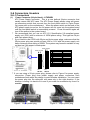
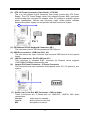
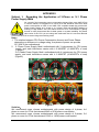
1
USER'S MANUAL
Of
AMD 770 Chipset
&
AMD SB710 Chipset Based
M/B for AM3 Processor
NO. G03-XBLUE77A4-F
Rev:1.0
Release date: May, 2010
Trademark:
* Specifications and information contained in this documentation are furnished for information use only, and are
subject to change at any time without notice, and should not be construed as a commitment by manufacturer.
Environmental Protection Announcement
Do not dispose this electronic device into the trash while discarding. To minimize pollution
and ensure environment protection of mother earth, please recycle.
ii
TABLE OF CONTENT
USER’S NOTICE .........................................................................................................iv
MANUAL REVISION INFORMATION .........................................................................iv
ITEM CHECKLIST .......................................................................................................iv
COOLING SOLUTIONS ..............................................................................................iv
CHAPTER 1 INTRODUCTION OF AMD 770 MOTHERBOARDS
1-1
1-2
1-3
1-4
FEATURES OF MOTHERBOARD ............................................................................. 1
1-1.1 SPECIAL FEATURES OF MOTHERBOARD ............................................... 2
SPECIFICATION ......................................................................................................... 3
PERFORMANCE LIST................................................................................................ 4
LAYOUT DIAGRAM.................................................................................................... 5
CHAPTER 2
2-1
2-2
2-3
2-4
2-5
2-6
2-7
CHAPTER 3
3-1
3-2
3-3
3-4
3-5
3-6
3-7
3-8
3-9
3-10
3-11
3-12
3-13
3-14
3-15
HARDWARE INSTALLATION
HARDWARE INSTALLATION STEPS ....................................................................... 7
CHECKING MOTHERBOARD'S JUMPER SETTING................................................ 7
INSTALL CPU ............................................................................................................. 8
2-3-1 GLOSSARY................................................................................................... 8
2-3-2 ABOUT AMD Athlon64 Socket AM2 ........................................................ 9
INSTALL MEMORY .................................................................................................... 10
EXPANSION CARDS.................................................................................................. 10
2-5-1 PROCEDURE FOR EXPANSION CARD INSTALLATION .......................... 10
2-5-2 ASSIGNING IRQS FOR EXPANSION CARD .............................................. 11
2-5-3 PCI-EXPRESS2.0 SLOT ............................................................................... 11
CONNECTORS, HEADERS........................................................................................ 12
2-6-1 CONNECTORS ............................................................................................. 12
2-6-2 HEADERS ..................................................................................................... 15
STARTING UP YOUR COMPUTER ........................................................................... 18
INTRODUCING BIOS
ENTERING SETUP ..................................................................................................... 19
GETTING HELP .......................................................................................................... 19
THE MAIN MENU........................................................................................................ 20
STANDARD BIOS FEATURES .................................................................................. 21
ADVANCED BIOS FEATURES .................................................................................. 22
3-5-1 CPU CONFIGURATION .............................................................................. 23
ADVANCED CHIPSET FEATURES ........................................................................... 23
3-6-1 MEMORY CONFIGURATION ..................................................................... 24
3-6-2 PCI EXPRESS CONFIGURATION............................................................. 25
INTEGRATED PERIPHERALS................................................................................... 25
POWER MANAGEMENT SETUP............................................................................... 27
MISCELLANEOUS CONTROL ................................................................................. 28
PC HEALTH STATUS ............................................................................................... 28
3-10-1 SMART FAN CONFIGURATION ............................................................... 29
THERMAL THROTTLING OPTIONS ........................................................................ 30
POWER USER OVERCLOCK SETTING .................................................................. 30
BIOS SECURITY FEATURES ................................................................................. 32
LOAD OPTIMAL/STANDARD DEFAULTS .............................................................. 33
SAVE CHNGES AND EXIT/DISCARD AND EXIT.................................................... 33
CHAPTER 4
DRIVER & FREE PROGRAM INSTALLATION
4-1 ATI INSTALL ATI DRIVER PACK ....................................................................... 35
4-2 SOUND INSTALL ALC HD AUDIO DRIVER ......................................................... 35
4-3 REALTEK
INSTALL REALTEK LAN CONTROLLER DRIVER ........................... 37
4-4 WIFI_N INSTALL RT2770 WIRELESS NETWORK................................................. 37
4-5 WIFI_BG INSTALL RTL8187 WIRELESS NETWORK ........................................... 38
4-6 RAID
INSTALL SATA RAID DRIVER AND UTILITY ........................................... 39
ii
4-7
4-8
4-9
4-10
4-11
4-12
4-13
4-14
4-15
NORTON
INSTALL NORTON ANTI-VIRUS TRIAL PROGRAM......................... 39
PC-HEALTH INSTALL MYGUARD HARDWARE MONITOR UTILITY .................. 40
OVERCLOCK INSTALL OVERCLOCK DRIVER UTILITY ..................................... 40
FUSION INSTALL FUSION DRIVERS AND TOOLS................................................. 41
HOW TO UPDATE BIOS ............................................................................................ 42
AMD PLATFORM RAID FUNCTION INSTALLATION .............................................. 42
PRO MAGIC PLUS FUNCTION INSRUCTION .......................................................... 45
G.P.I.FUNCTION INSTALLATION STEPS................................................................. 47
G.P.I. LED DISPLAY................................................................................................... 49
APPENDIX...................................................................................................................50
Safety Environmental Instruction
z
Avoid the dusty, humidity and temperature extremes. Do not place the product in
any area where it may become wet.
z
0 to 40 centigrade is the suitable temperature. (The figure comes from the request
of the main chipset)
z
Generally speaking, dramatic changes in temperature may lead to contact
malfunction and crackles due to constant thermal expansion and contraction from
the welding spots’ that connect components and PCB. Computer should go
through an adaptive phase before it boots when it is moved from a cold
environment to a warmer one to avoid condensation phenomenon. These water
drops attached on PCB or the surface of the components can bring about
phenomena as minor as computer instability resulted from corrosion and oxidation
from components and PCB or as major as short circuit that can burn the
components. Suggest starting the computer until the temperature goes up.
z
The increasing temperature of the capacitor may decrease the life of computer.
Using the close case may decrease the life of other device because the higher
temperature in the inner of the case.
z
Attention to the heat sink when you over-clocking. The higher temperature may
decrease the life of the device and burned the capacitor.
iii
USER’S NOTICE
COPYRIGHT OF THIS MANUAL BELONGS TO THE MANUFACTURER. NO PART OF THIS
MANUAL, INCLUDING THE PRODUCTS AND SOFTWARE DESCRIBED IN IT MAY BE
REPRODUCED, TRANSMITTED OR TRANSLATED INTO ANY LANGUAGE IN ANY FORM OR BY
ANY MEANS WITHOUT WRITTEN PERMISSION OF THE MANUFACTURER.
THIS MANUAL CONTAINS ALL INFORMATION REQUIRED TO USE AMD 770 MOTHERBOARD
AND WE DO ASSURE THIS MANUAL MEETS USER’S REQUIREMENT BUT WILL CHANGE,
CORRECT ANY TIME WITHOUT NOTICE. MANUFACTURER PROVIDES THIS MANUAL “AS IS”
WITHOUT WARRANTY OF ANY KIND, AND WILL NOT BE LIABLE FOR ANY INDIRECT, SPECIAL,
INCIDENTIAL OR CONSEQUENTIAL DAMAGES (INCLUDING DAMANGES FOR LOSS OF
PROFIT, LOSS OF BUSINESS, LOSS OF USE OF DATA, INTERRUPTION OF BUSINESS AND
THE LIKE).
PRODUCTS AND CORPORATE NAMES APPEARING IN THIS MANUAL MAY OR MAY NOT BE
REGISTERED TRADEMARKS OR COPYRIGHTS OF THEIR RESPECTIVE COMPANIES, AND
THEY ARE USED ONLY FOR IDENTIFICATION OR EXPLANATION AND TO THE OWNER’S
BENEFIT, WITHOUT INTENT TO INFRINGE.
Manual Revision Information
Reversion
1.0
Revision History
First Edition
Date
May, 2010
Item Checklist
5
5
5
5
5
AMD 770 Chipset based motherboard
User’s Manual
DVD for Motherboard Utilities
I/O Back Panel Shield
SATA Cable
AMD Processor Family
Cooling Solutions
As processor technology pushes to faster speeds and higher performance with increasing
operation clock, thermal management becomes increasingly crucial while building computer
systems. Maintaining the proper computing environment without thermal increasing is the key to
reliable, stable, and 24 hours system operation. The overall goal is keeping the processor
below its specified maximum case temperature. Heatsinks induce improved processor heat
dissipation through increasing surface area and concentrated airflow from attached active
cooling fans. In addition, interface materials allow effective transfers of heat from the
processor to the heatsink. For optimum heat transfer, AMD recommends the use of thermal
grease and mounting clips to attach the heatsink to the processor.
Please refer to the website below for collection of heatsinks evaluated and recommended for
Socket AM2+ processors by AMD. In addition, this collection is not intended to be a
comprehensive listing of all heatsinks that support Socket AM3 processors.
iv
Chapter 1
1-1
Introduction of AMD 770Motherboards
Features of motherboard
The AMD 770 chipset motherboard series are based on the latest AMD 770 Chipset
and the SB710 chipset which supports the innovative AMD AM3 series Phenom™ II x
6,Phenom™ II x 4,Phenom™ II x 3,Phenom™ II x2 , AthlonII™ x4 , Athlon II™ x3 ,
Athlon II™ x2 and Sempron™ processor under 95W power consumption. With an
integrated low-latency high-bandwidth DDRIII memory controller and a
highly-scalable Hyper Transport technology-based system bus up to HT 3.0.
AMD770Platform Processor Chipset motherboard series deliver the outstanding system
performance and professional desktop platform solution processors.
The AMD770 Series motherboards support new generation AM3 processors with
integrated DDRIII memory controller for two dual channel DDRIII 800/ DDRIII
1066/DDRIII 1333 modules up to 8GB. The motherboard is embedded with SB710
chipset of providing ULTRA ATA 133 connectors and Serial ATA2 with RAID 0, 1, 10,
JBOD functions which support up to two IDE devices and six Serial ATA2 devices to
accelerate hard disk drives and guarantee the data security without failure in
advanced computing performance.
The AMD 770 motherboards provide 10/100/1000 LAN function with Gigabit LAN chip
which supports optional 10/100/1000Mbps data transfer rate. And the embedded HD
6-channel ALC662 HD Audio CODEC is fully compatible with Sound Blaster Pro
standards that offer you with the home cinema quality and satisfying software
compatibility.
The AMD 770 Series motherboards deliver outstanding value and performance for
gamers, with a true bandwidth design for Multi-GPU configurations. This high
bandwidth architecture in the AMD 770 chipset is combined with the flexibility for
single or dual card configurations.
This motherboard series offers one PCI-Express 2.0 x16 By 16-lane graphics slot,one
PCI-Express 2.0 x16 By 4-lane graphics slots and one PCI-Express 2.0 x1 graphics
slot for astonishing performance with brilliant and intense 3D graphics.The
motherboard also carries two 32-bit PCI slots guarantee the rich connectivity for the
I/O peripheral devices.
Embedded USB controllers as well as capability of expanding to 8 of USB2.0
functional ports delivering 480Mb/s bandwidth of rich connectivity, these
motherboards meet the future USB demands which are also equipped with hardware
monitor function on system to monitor and protect your system and maintain your
non-stop business computing.
1
Some special features--- CPU Thermal Throttling/ CPU VID / /CPU Vcore OC CON /G.P.I
Function/WI-FI Header/Power-on Button/Reset Button on this motherboard are
designed for power user to use the over-clocking function in more flexible ways. But
please be caution that the over-clocking maybe causes the fails in system reliabilities.
This motherboard provides the guaranteed performance and meets the demands of
the next generation computing. But if you insist to gain more system performance with
variety possibilities of the components you choose, please be careful and make sure
to read the detailed descriptions of these value added product features, please get
them in the coming section.
1-1.1 Special Features of Motherboard
CPU Thermal Throttling Technology--- (The CPU Overheat Protection
Technology)
To prevent the increasing heat from damage of CPU or accidental shutdown while at
high workload, the CPU Thermal Throttling Technology will force CPU to enter
partially idle mode from 87.5% to 12.5% according to preset CPU operating
temperature in BIOS (from 40℃ to 90℃). When the system senses the CPU
operating temperature reaching the preset value, the CPU operating bandwidth will be
decreased to the preset idle percentage to cool down the processor. When at
throttling mode the beeper sound can be optionally selected to indicate it is in working.
(For detail operating please read Section 3-11 Bi-turbo Configuration)
CPU VID--- (Shift to Higher Performance)
The CPU voltage can be adjusted for the precisely over-clocking of extra demanding
computing performance.
CPU Vcore OC-CON ---( High-polymer Solid Electrolysis Aluminum
Capacitors)
CPU Vcore input/output adopt OC-CON solid capacitors.The working temperature is
from 55 degrees Centigrade below zero to 125 degrees Centigrade, OC-CON
capacitors possess superior physical characteristics that can be while reducing the
working temperature between 20 degrees Centigrade each time, intact extension 10
times of effective product operation lives, at not rising degrees Centigrade of working
temperatures each time a relative one, life of product decline 10% only too.
G.P.I Function—(Green power indicator function)
The full name of G.P.I technology is Green Power Indicator technology, obviously
technology utilized to low power consumption. G.P.I is a technology with remarkable
power saving function:
WI-FI Technology
WI-FI--Full name is wireless Fidelity. It has been used in notebook, mobile phone,
PDA, digital cameras and Mobile Terminals widely. With WI-FI. We do not need to
worry about the speed and high spending when we are dialing long-distance calls,
browsing web pages, receiving and sending E-mails, loading music, delivering digital
photos.
Power-on Button
You can easily start the computer by pressing down this button for a few seconds,
without troubling yourself to locate the front panel jumpers to find the Power on
jumper.
Reset Button
You can easily restart the computer by pressing down this button for a few seconds,
without troubling yourself to locate the front panel jumpers to find the reset jumper.
2
3D Audio
OP with two-stage Butterworth filter and quadruple noninverting amplifier enhances
bass effect under the 100MHz range to perfect audio effect, brings you stunning
shock experience in video game, true-to-life simulated feeling when watching films
and the greatest touch as that in the concert.
1-2
Specification
Spec
Description
Gigabit LAN
z
z
6 CH-Audio
z
z
ATX form factor; PCB size: 29.5cm x20.0cm
AMD 770 North Bridge Chipset
AMD SB710 South Bridge Chipset
AMD AM3 series Phenom™ II x 6,Phenom™ II x 4 ,Phenom™ II
x 3,Phenom™ II x2 , AthlonII™ x4 , Athlon II™ x3 , Athlon II™ x2
and Sempron™ processor
CPU Power consumption should be under 95 W
Support HT 3.0
240-pin DDRIII Module socket x 2
Support 2pcs DDRIII800/ 1066/ 1333 Modules Expandable to 8GB
Dual channel supported
PCI-Express2.0 x16 by 16 Lane 1pcs
PCI-Express2.0 x16 by 4 Lane 1pcs
PCI-Express2.0 x1 slot 1pcs
32-bit PCI slot x 2pcs
One IDE controllers support PCI Bus Mastering, ATA PIO/DMA
and the ULTRA DMA 33/66/100/133 functions that deliver the data
transfer rate up to 133 MB/s for 2 IDE Devices and for 6 Serial
ATA2 ports providing 300 MB/sec data transfer rate with RAID 0, 1,
10 and JBOD functions
Integrated PCI-E Gigabit LAN chip.
Support Fast Ethernet LAN function of providing
10Mb/100Mb/1000 Mb/s data transfer rate
ALC 662 6-channel HD Audio Codec integrated
Audio driver and utility included
BIOS
z
z
z
z
z
z
z
z
z
z
AMI 8MB Flash ROM BIOS
PS/2 keyboard and PS/2 mouse connectors
SPDIF_OUT connector x1
Serial port connector x1
USB2.0 port connector x 4 and headers x 2
RJ-45 LAN Connector x1
Audio connector x1 (Line-in, Line-out, MIC/6CH Audio)
Floppy disk drive connector x1/ Hard disk drive connector x1
HDMI_SPDIF header x1/ IR Connector x1
WI-FI Header x1
Design
Chipset
z
z
z
z
CPU Socket
Memory Socket
Expansion Slot
z
z
z
z
z
z
z
z
z
z
Integrate IDE and
Serial ATA2 RAID
Multi I/O
3
1-3
Performance List
The following performance data list is the testing result of some popular benchmark
testing programs. These data are just referred by users, and there is no responsibility
for different testing data values gotten by users (the different Hardware & Software
configuration will result in different benchmark testing results.)
Performance Test Report
CPU: HDZ555WFK2DGM
DRAM: APACER2GB 1333
VGA Card: HD3850
Hard Disk Driver: MAXTOR80GB
BIOS: T02 12-24-2009
30771
3DMark Vantage
9275
3D Mark 2006
18588
3D Mark 2005
PCMark2005
7143/7733/5663
System / CPU / Memory
8902/5029
Graph / HDD
51.5
Content Creation Winstone 2004
27.2
Business Winstone 2004
Winbench 99 V2.0:
20700
Business/Hi-end
SISMark 2004: SISMark Rating(Internet Content Creation / Office Productivity )
470
SISMark 2004
407/569
3D Creation/2D Creation
447
Web publication
196/366
Communication/ Document
287
Data Analysis
SISOFT Sandra 2004 : 1.CPU Arithmetic Benchmark 2.Memory bandwidth Benchmark
3.CPU Multi-Media Benchmark
20.95
1.Dhrystone ALU
GIPS
20.82
Whetstone FPU iSSE2
GFLOPS
60.84/27.21/14.89
2.Int/Float Buffered iSSE2 MB/S
10.78/10.78
3.Integer/Floating-Point IT/S
528.554199/170.406433
UT2003 Benchmark (flyby/botmatch)
747.4710.5
Quake3 DEMO1 /DEMO2 FPS
0.21.641"
Super Pi (1M)
Second
CPUZ System / CPU Clock
200*16 2000
4
1-4
Layout Diagram
RJ45 LAN
PS/2 Mouse Port
SPDIF OUT Connector
Serial Port Connector
Line-IN
Line-OUT
MIC-IN
PS/2 Keyboard Port
USB Ports
ATX 12V Power Connector
G.P.I. LED
CPUFAN
PS2 KB/Mouse Port
(KB)
SPDIF OUT
Coonector
DDR3 Socket x 2
KB/USB Power on (JP1)
ATX Power Conn.
Serial Port
Connector
USB Port
(CN1)
RJ-45 Over
USB Connector
(UL1)
Audio Connector
(CN2)
SYSFAN2
ATA 133 IDE
Conn.(IDE1)
CPU Socket
4-pin PWR Connector
AMD 770 Chipset
PCI Express2.0 x16
by 16-lane
Gigabit LAN Chip
SB710 chipset
Power on Button
Reset Button
8MBit Flash ROM BIOS
PCI Express2.0 x1
PCI Express2.0 x16
by 4-lane
Realtek ALC662
Audio Codec
HDMI-SPDIF
Header
PCI Slots
Clear CMOS(JBAT)
Serial-ATAII Connectors
Wi-Fi Header
Power LED Header
Speaker Header
Audio Header
Front Panel Header
3D Audio Button
USB Port Headers Floppy Connector
IR Header
5
SYSFAN1
Jumpers
Jumper
JP1
JBAT
Name
Description
Keyboard/USB Power On Enabled/Disabled 3-pin Block
CMOS RAM Clear
2-pin Block
Connectors
Connector
ATXPWR1
ATX12V1
KB1
Name
ATX Power Connector
ATX 12V Power Connector
PS/2 Mouse & PS/2 Keyboard
Connector
USB from CN1, UL1 USB2.0 Port Connector
RJ-45LAN from UL1 Gigabit LAN Port Connector
J2
CrossFire Power Connector
6-CH HD Audio Connector
AUDIO:CN2
FDD1
Floppy Driver Connector
IDE1
Primary/Secondary IDE Connector
Serial ATAII IDE Connectors
SATA1~SATA6
SPDIF_OUT1
Coaxial SPDIF_OUT Connector
COM1
Serial Port Connector
Description
24-pin Block
8-pin Block
6-pin Female
4-pin Connector
8-pin Connector
4-Pin Block
3- phone jack Conn.
34-pin Block
40-pin Block
7-pin Connector
1-phone Connector
9-pin Block
Headers
Header
AUDIO1
USB1, USB2
SPEAK1
PWR LED1
JW_FP1
(Reset/HDLED/Power
Button/PWR LED)
SYSFAN1/2
CPUFAN
IR1
HDMI_SPDIF
WI-FI1
Name
SPEAKER, MIC header
USB Port Headers
PC Speaker connector
Power LED
Front Panel Header
(including IDE activity LED/Reset
switch / Power On Button lead)
FAN Headers
FAN Header
IR infrared module Headers
SPDIF Out header
Wi-Fi header
Description
9-pin Block
9-pin Block
4-pin Block
3-pin Block
9-pin Block
3-pin Block
4-pin Block
5-pin Block
2-pin Block
11-pin Block
Expansion Sockets
Socket/Slot
ZIF Socket AM2
DDRIII1~2
PCI1∼ PCI2
PE2
PE1,PE3
Name
CPU Socket
DDRIII Module Socket
PCI Slots
PCI-Express2.0 x1Slot
PCI-Express2.0 x16 Slot
Description
940-pin mPGAB AMD CPU Socket
240-pin DDRII Module Socket
32-bit PCI Local Bus Expansion slots
PCI-Express2.0 x1 Expansion Slots
PCI-Express2.0 x16 Expansion Slots
6
Chapter 2
Hardware Installation
WARNING!
2-1
Turn off your power when adding or removing expansion cards or
other system components. Failure to do so may cause severe
damage to both your motherboard and expansion cards.
Hardware installation Steps
Before using your computer, you had better complete the following steps:
1. Check motherboard jumper setting
2. Install CPU and Fan
3. Install System Memory (DIMM)
4. Install Expansion cards
5. Connect IDE and Front Panel /Back Panel cable
6. Connect ATX Power cable
7. Power-On and Load Standard Default
8. Reboot
9. Install Operating System
10. Install Driver and Utility
2-2
(1)
Checking Motherboard’s Jumper Setting
Keyboard/USB function Enabled/Disabled: JP1
JP1
JP1
1-2 Closed KB/USB Power ON Disable (Default)
2-3 Closed KB/USB Power ON Enabled
Keyboard/Mouse & USB Power On Setting
(2)
CMOS RAM Clear (2-pin): JBAT
A battery must be used to retain the motherboard configuration in CMOS RAM
short 1-2 pins of JBAT to clear the CMOS data.
WARNNING:Please remove or turn off the power supply before CMOS clear!
To clear the CMOS, follow the procedure below:
1. Turn off the system and unplug the AC power
2. Remove ATX power cable from ATX power connector
3. Locate JBAT and short pins 1-2 for a few seconds, if shorted with the jump cap,
short for a few seconds then pull out the hat.
4. Connect ATX power cable back to ATX power connector
7
Note: When should clear CMOS
1. Troubleshooting
2. Forget password
3. After over clocking system boot fail
JBAT
1-2 Open: Normal
1-2 Short: CMOS Clear
CMOS Clear Setting
2-3
Install CPU
2-3-1 Glossary
Chipset (or core logic) - two or more integrated circuits which control the interfaces
between the system processor, RAM, I/O devises, and adapter cards.
Processor slot/socket - the slot or socket used to mount the system processor on
the motherboard.
Slot (PCI-E, PCI, RAM) - the slots used to mount adapter cards and system RAM.
PCI - Peripheral Component Interconnect - a high speed interface for video cards,
sound cards, network interface cards, and modems; runs at 33MHz.
PCI Express- Peripheral Component Interconnect Express- a high speed interface for
video cards, sound cards, network interface cards, and modems.
PCI Express2.0- Peripheral Component Interconnect Express2.0, developed in 2003,
the speed of each line doubled from the previous PCI-E of 2.5Gbps to 5 Gbps.
Serial Port - a low speed interface typically used for mouse and external modems.
Parallel Port - a low speed interface typically used for printers.
PS/2 - a low speed interface used for mouse and keyboards.
USB - Universal Serial Bus - a medium speed interface typically used for mouse,
keyboards, scanners, and some digital cameras.
Sound (interface) - the interface between the sound card or integrated sound
connectors and speakers, MIC, game controllers, and MIDI sound devices.
LAN (interface) - Local Area Network - the interface to your local area network.
BIOS (Basic Input/Output System) - the program logic used to boot up a computer
and establish the relationship between the various components.
Driver - software, which defines the characteristics of a device for use by another
device or other software.
Processor - the "central processing unit" (CPU); the principal integrated circuit used
for doing the "computing" in "personal computer"
Front Side Bus Frequency - the working frequency of the motherboard, which is
generated by the clock generator for CPU, DRAM and PCI BUS.
8
CPU L2 Cache - the flash memory inside the CPU, normal it depend on CPU type.
2-3-2 About CPU Socket
This motherboard provides a surface mount, Zero Insertion Force (ZIF) socket,
referred to as the mPGA940 socket supports AMD Athlon64 processor in the package
utilizes Flip-Chip Pin Grid Array package technology.
The CPU that comes with the motherboard should have a cooling fan attached to
prevent overheating. If this is not the case, then purchase a correct cooling fan before
you turn on your system.
WARNING!
Be sure that there is sufficient air circulation across the processor’s
heatsink and CPU cooling FAN is working correctly, otherwise it may
cause the processor and motherboard overheat and damage, you
may install an auxiliary cooling FAN, if necessary.
To install a CPU, first turn off your system and remove its cover. Locate the ZIF
socket and open it by first pulling the level sideways away from the socket then
upward to a 90-degree angle. Insert the CPU with the correct orientation as shown
below. he notched corner should point toward the end of the level. Because the
CPU has a corner pin for two of the four corners, the CPU will only fit in the orientation
as shown.
Socket AM2
Colde n Arrow
CPU ZIF mPGAB Socket
When you put the CPU into the ZIF socket, No force required to insert of the CPU, and
then press the level to locate position slightly without any extra force.
9
2-4
Install Memory Modules
This motherboard provides two 240-pin DDR III SDRAM DUAL INLINE MEMORY
MODULES sockets for DDR III memory (DDRIII1, DDRIII2) SDRAM expandable to
maximum memory volume of 8 GB.
Valid Memory Configuration for DDR III
Bank
240-Pin DIMM
PCS Maximum Capacity
DDR III 1
DDR III 2
Total
DDR III 800/ 1066/1333
DDR III 800/ 1066/1333
System Memory (Max. 4 GB)
X1
X1
2
4 GB
4 GB
8 GB
NOTICE!
1.
2.
Dual channel function only supports when 2 DIMM Modules plug in either both DDR III
1 & DDR III 2.
Memory modules installed must be of the same type, same size, and same frequency
for dual channel function.
DDRII I2
DDRIII1
Install modules to your motherboard is not difficult, you can refer to figure below to see
how to install a 240-Pin a DDRIII 800/ 1066 / 1333 SDRAM module.
DDRIII1 & DDRIII2: Dual Channel
NOTICE!
2-5
When you install DIMM module fully into the DIMM socket the eject tab should be
locked into the DIMM module very firmly and fit into its indention on both sides.
Expansion Cards
2-5-1 Procedure For Expansion Card Installation
1. Read the documentation for your expansion card and make any necessary
hardware or software setting for your expansion card such as jumpers.
2. Remove your computer’s cover and the bracket plate on the slot you intend to use.
3. Align the card’s connectors and press firmly.
4. Secure the card on the slot with the screen you remove above.
5. Replace the computer system’s cover.
6. Set up the BIOS if necessary.
7. Install the necessary software driver for your expansion card.
10
2-5-2 Assigning IRQs For Expansion Card
Some expansion cards need an IRQ to operate. Generally, an IRQ must exclusively
assign to one use. In a standard design, there are 16 IRQs available but most of
them are already in use.
Standard Interrupt Assignments
IRQ
0
1
2
3*
4*
5*
6*
7*
8
9*
10 *
11 *
12 *
13
14 *
15 *
Priority
N/A
N/A
N/A
8
9
6
11
7
N/A
10
3
2
4
N/A
5
1
Standard function
System Timer
Keyboard Controller
Programmable Interrupt
Communications Port (COM2)
Communications Port (COM1)
Sound Card (sometimes LPT2)
Floppy Disk Controller
Printer Port (LPT1)
System CMOS/Real Time Clock
ACPI Mode when enabled
IRQ Holder for PCI Steering
IRQ Holder for PCI Steering
PS/2 Compatible Mouse Port
Numeric Data Processor
Primary IDE Channel
Secondary IDE Channel
* These IRQs are usually available for ISA or PCI devices.
IMPORTANT!
If using PCI cards on shared slots, make sure that the drivers support “Shared
IRQ” or that the cards don’t need IRQ assignments. Conflicts will arise between the
two PCI groups that will make the system unstable or cards inoperable.
2-5-3 Expansion Slots
This motherboard series offers one PCI-Express2.0 x16 By 16-lane graphics slot,one
PCI-Express2.0 x16 By 4-lane graphics slots and one PCI-Express2.0 x1 graphics
slot for astonishing performance with brilliant and intense 3D graphics. The
motherboard also carries two 32-bit PCI slots guarantee the rich connectivity for the
I/O peripheral devices.
PCI-E 2.0x1 Slot
PCI-E 2.0x16 Slot By 16-lane
32-bit PCI Slots
11
PCI-E 2.0x16 Slot By 4-lane
2-6 Connectors, Headers
2-6-1 Connectors
(1)
Power Connector (24-pin block) : ATXPWR1
ATX Power Supply connector: This is a new defined 24-pins connector that
usually comes with ATX case. The ATX Power Supply allows using soft power
on momentary switch that connect from the front panel switch to 2-pins Power
On jumper pole on the motherboard. When the power switch on the back of the
ATX power supply turned on, the full power will not come into the system board
until the front panel switch is momentarily pressed. Press this switch again will
turn off the power to the system board.
** We recommend that you use an ATX 12V Specification 2.0-compliant power
supply unit (PSU) with a minimum of 350W power rating. This type has 24-pin
and 4-pin power plugs.
** If you intend to use a PSU with 20-pin and 4-pin power plugs, make sure that the
20-pin power plug can provide at least 15A on +12V and the power supply unit
has a minimum power rating of 350W. The system may become unstable or may
not boot up if the power is inadequate.
ROW1 ROW2
ROW1 ROW2
PIN
Pin 1
Pin 1
20-Pin
24-Pin
ROW1
ROW2
1
3.3V
3.3V
2
3.3V
-12V
3
GND
GND
4
5V
Soft Power On
5
GND
GND
6
5V
GND
7
GND
GND
8
Power OK
-5V
9
+5V (for Soft Logic)
+5V
10
+12V
+5V
11
+12V
+5V
12
+3V
GND
** If you are using a 20-pin power plug, please refer to Figure1 for power supply
connection. Power plug form power supply and power connectors from
motherboard both adopt key design to avoid mistake installation. You can insert
the power plug into the connector with ease only in the right direction. If the
direction is wrong it is hard to fit in and if you make the connection by force if is
possible.
Figure1:20-pin power plug
Figure 2:24-pin power plug
12
(2) ATX 12V Power Connector (8-pin block) : ATX12V1
This is a new defined 8-pins connector that usually comes with ATX Power
Supply. The ATX Power Supply which fully supports Socket AM2+ processor
must including this connector for support extra 12V voltage to maintain system
power consumption. Without this connector might cause system unstable
because the power supply can not provide sufficient current for system.
Pin 1
(3) PS/2 Mouse & PS/2 Keyboard Connector: KB1
The connectors are for PS/2 keyboard and PS/2 Mouse.
(4) USB Port connector: USB from CN1, UL1
The connectors are 4-pin connector that connects USB devices to the system
board.
(5) LAN Port connector: RJ-45 LAN from UL1
This connector is standard RJ45 connector for Network which supports
10M/100Mb/1000Mbps data transfer rate
(6) Large 4-Pin Power Connector: J2 Power Connector
The connectors are 4-pin connector that supports extra 12V / 5V power to your
system .
(7) Audio Line-In, Lin-Out, MIC Connector : CN2 for Audio
These Connectors are 3 Phone-Jack for LINE-OUT, LINE-IN, MIC audio
connections.
Line-out :
Audio output to speaker
Audio input to sound chip
Line-in :
MIC :
Microphone Connector
13
S/PDIF_ OUT Connector
PS/2 Mouse Port
RJ-45 LAN Connector
Line-IN
Serial Port Connector
Line-OUT
PS/2 Keyboard Port
MIC-IN
USB Port Connector
(8)
Floppy drive Connector (34-pin block): FDD1
This connector supports the provided floppy drive ribbon cable. After connecting
the single plug end to motherboard, connect the two plugs at other end to the
floppy drives.
FDD
Pin 1
Floppy Drive Connector
(9)Primary IDE Connector (40-pin block): IDE1
This connector supports the provided IDE hard disk ribbon cable. After
connecting the single plug end to motherboard, connect the two plugs at other
end to your hard disk(s). If you install two hard disks, you must configure the
second drive to Slave mode by setting its jumpers accordingly. Please refer to
the documentation of your hard disk for the jumper settings.
IDE1
Pin 1
IDE Connector
• Two hard disks can be connected to each connector. The first HDD is referred to
as the “Master” and the second HDD is referred to as the “Slave”.
• For performance issues, we strongly suggest you don’t install a CD-ROM or
DVD-ROM drive on the same IDE channel as a hard disk. Otherwise, the system
performance on this channel may drop.
14
(10) Serial-ATAII Port connector:SATA1~SATA6
These connectors support the provided Serial ATA2 hard disk cables to connecting
the motherboard with serial ATAII hard disks.
SATA1
SATA2
SATA3
SATA4
SATA6
SATA5
Serial-ATA
Port Connectors
(11)Coaxial SPDIF_OUT connector: SPDIF_OUT1
The SPDIF output is capable of providing digital audio to external speakers or
compressed AC3 data to an external Dolby digital decoder. Use this feature only
when your stereo system has digital input function.
(12) Serial COM Port: COM1
COM1 is the 9-pin connector. The On-board serial port can be disabled through
BIOS SETUP.
2-6-2 Headers
AUDIO
LINE2-JD
MIC2-JD
KEY
Audio-GND
Audio-JD
(1) Line-Out/MIC Header for Front Panel (9-pin): AUDIO1
These headers connect to Front Panel Line-out, MIC connector with cable.
2
10
Pin 1
Sense-FB
Lineout2-L
Lineout2-R
MIC2-L
MIC2-R
9
Line-Out, MIC Headers
(2) USB Port Headers (9-pin): USB1/USB2
These headers are used for connecting the additional USB port plug. By
attaching an option USB cable, your can be provided with two additional USB
plugs affixed to the back panel.
15
+DATA
GND
OC
VCC
-DATA
VCC
-DATA
+DATA
GND
OC
VCC
USB2
-DATA
USB1
+DATA
GND
VCC
-DATA
+DATA
GND
Pin 1
Pin 1
USB Port Headers
JW FP
PWRBTN
GND
PWRLED
Pin 1
PWRLED
PWRBTN
VCC5
PWR LED
(3) Speaker connector: SPEAK1
This 4-pin connector connects to the case-mounted speaker. See the figure below.
(4) Power LED: PWR LED1/ PWR LED
The Power LED is light on while the system power is on. Connect the Power
LED from the system case to this pin.
(5) IDE Activity LED: HD LED
This connector connects to the hard disk activity indicator light on the case.
(6) Reset switch lead: RESET
This 2-pin connector connects to the case-mounted reset switch for rebooting
your computer without having to turn off your power switch. This is a preferred
method of rebooting in order to prolong the lift of the system’s power supply.
See the figure below.
(7)Power switch: PWR BTN
This 2-pin connector connects to the case-mounted power switch to power
ON/OFF the system.
SPEAK
RESET
VCC5
HDDLE
GND
RSTSW
NC
HDLED
VCC5
Pin 1
SPKR
NC
GND
Pin 1
System Case Connections
(8) FAN Power Headers: SYSFAN1, SYSFAN2 (3-pin); CPUFAN (4-pin)
These connectors support cooling fans of 350mA (4.2 Watts) or less, depending
on the fan manufacturer, the wire and plug may be different. The red wire
should be positive, while the black should be ground. Connect the fan’s plug to
the board taking into consideration the polarity of connector.
16
CPUFAN IN
CPUFAN OUT
GND
+12V
CPUFAN
4
1
1
3
SYSFAN2
1
3
SYSFAN1
FAN Power Headers
GND
IR
IRRX
(9) IR infrared module Headers (5-pin): IR1
This connector supports the optional wireless transmitting and receiving infrared
module. You must configure the setting through the BIOS setup to use the IR
function.
2
6
5
NC
VCC5
IRTX
Pin 1
IR infrared module Headers
(10) HDMI_SPDIF Out header: HDMI_SPDIF
The SPDIF output is capable of providing digital audio to external speakers or
compressed AC3 data to an external Dolby digital decoder. Use this feature only
when your stereo system has digital input function.
GND
HDMI_SPDIF_OUT
1 2
HDMI_SPDIF Header
(11) WI-FI Header: WI-FI1
This header supports WI-FI Function. Connect the wireless local area network
adapter to this header. It allows you to create a wireless environment and enjoy the
convenience of wireless network connectivity.
17
N.C
+3.3V
D1+
GND
USB+5
D1-
WI-FI
2
12
Pin 1
N.C
GND
D0D0+
USB+5
11
WI-FI Headers
2-7
Starting Up Your Computer
1. After all connection are made, close your computer case cover.
2. Be sure all the switch are off, and check that the power supply input voltage is set
to proper position, usually in-put voltage is 220V∼240V or 110V∼120V depending
on your country’s voltage used.
3. Connect the power supply cord into the power supply located on the back of your
system case according to your system user’s manual.
4. Turn on your peripheral as following order:
a. Your monitor.
b. Other external peripheral (Printer, Scanner, External Modem etc…)
c. Your system power. For ATX power supplies, you need to turn on the power
supply and press the ATX power switch on the front side of the case.
5. The power LED on the front panel of the system case will light. The LED on the
monitor may light up or switch between orange and green after the system is on.
If it complies with green standards or if it is has a power standby feature. The
system will then run power-on test. While the test is running, the BIOS will alarm
beeps or additional message will appear on the screen.
If you do not see any thing within 30 seconds from the time you turn on the power.
The system may have failed on power-on test. Recheck your jumper settings and
connections or call your retailer for assistance.
6. During power-on, press <Delete> key to enter BIOS setup. Follow the
instructions in BIOS SETUP.
7. Power off your computer: You must first exit or shut down your operating
system before switch off the power switch. For ATX power supply, you can press
ATX power switching after exiting or shutting down your operating system. If you
use Windows 9X, click “Start” button, click “Shut down” and then click “Shut
down the computer?” The power supply should turn off after windows shut
down.
18
Chapter 3
Introducing BIOS
The BIOS is a program located on a Flash Memory on the motherboard. This
program is a bridge between motherboard and operating system. When you start
the computer, the BIOS program will gain control. The BIOS first operates an
auto-diagnostic test called POST (power on self test) for all the necessary hardware, it
detects the entire hardware device and configures the parameters of the hardware
synchronization. Only when these tasks are completed done it gives up control of
the computer to operating system (OS). Since the BIOS is the only channel for
hardware and software to communicate, it is the key factor for system stability, and in
ensuring that your system performance as its best.
In the BIOS Setup main menu of Figure 3-1, you can see several options. We will
explain these options step by step in the following pages of this chapter, but let us first
see a short description of the function keys you may use here:
•
Press <Esc> to quit the BIOS Setup.
•
Press ↑ ↓ ← → (up, down, left, right) to choose, in the main menu, the option you
want to confirm or to modify.
•
Press <F10> when you have completed the setup of BIOS parameters to save
these parameters and to exit the BIOS Setup menu.
•
Press <+>/<–> keys when you want to modify the BIOS parameters for the active
option.
3-1
Entering Setup
Power on the computer and by pressing <Del> immediately allows you to enter Setup.
If the message disappears before your respond and you still wish to enter Setup,
restart the system to try again by turning it OFF then ON or pressing the “RESET”
button on the system case. You may also restart by simultaneously pressing <Ctrl>,
<Alt> and <Delete> keys. If you do not press the keys at the correct time and the
system does not boot, an error message will be displayed and you will again be asked
to
Press
<Del> to enter Setup
3-2
Getting Help
Main Menu
The on-line description of the highlighted setup function is displayed at the bottom of
the screen.
Status Page Setup Menu/Option Page Setup Menu
19
Press F1 to pop up a small help window that describes the appropriate keys to use
and the possible selections for the highlighted item. To exit the Help Window, press
<Esc>.
3-3
The Main Menu
Once you enter AMI BIOS Setup Utility, the Main Menu (Figure 3-1) will appear on the
screen. The Main Menu allows you to select from 12 setup functions and 2 exit
choices. Use arrow keys to select among the items and press <Enter> to accept or
enter the sub-menu.
Figure 3-1
Standard BIOS Features
Use this Menu for basic system configurations.
Advanced BIOS Features
Use this menu to set the Advanced Features available on your system.
Advanced Chipset Features
Use this menu to change the values in the chipset registers and optimize your
system’s performance.
Integrated Peripherals
Use this menu to specify your settings for integrated peripherals.
Power Management Features
Use this menu to specify your settings for power management.
Miscellaneous Control
Use this menu to specify your settings for Miscellaneous Control.
PC Health Status
This entry shows your PC health status.
Thermal Throttling Function
The selection is set for activating the active CPU Thermal Protection by flexible CPU
loading adjustment in the range of temperature you define.
User Overclock Settings
Use this menu to specify your settings (frequency, Voltage) for overclocking demand.
20
BIOS Security Features
This entry for setting Supervisor password and User password
Load Optimal Defaults
Use this menu to load the BIOS default values these are setting for optimal performances
system operations for performance use.
Load Standard Defaults
This menu uses a minimal performance setting, but the system would run in a stable
way.
Save Changes and Exit
Save CMOS value changes to CMOS and exit setup.
Discard Changes ans Exit
Abandon all CMOS value changes and exit setup.
3-4
Standard BIOS Features
The items in Standard BIOS Setup Menu are divided into several categories. Each
category includes no, one or more than one setup items. Use the arrow keys to
highlight the item and then use the <+> or <-> and numerical keyboard keys to select
the value you want in each item.
System Date
The date format is <day><month><date><year>.
Day of the week, from Sun to Sat, determined by BIOS. Read-only.
Day
The month from Jan. through Dec.
Month
The date from 1 to 31 can be keyed by numeric function keys.
Date
The year depends on the year of the BIOS.
Year
System Time
The time format is <hour><minute><second>.
Primary IDE 0 Master / Slave
SATA Channel 1, 2, 3, 4, 5, 6
While entering setup, BIOS auto detest the presence of IDE devices. This displays
the status of auto detection of IDE devices.
Type: The optional settings are: Not Installed; Auto; CD/DVD and ARMD
21
LBA/Large Mode: The optional settings are Auto; Disabled.
Block (Multi-Sector Transfer): The optional settings are: Disabled and Auto.
PIO Mode: the optional settings are: Auto, 0, 1, 2, 3 and 4.
DMA MODE: the optional settings are Auto, SWDMAn, MWDMAn , UDMAn.
S.M.A.R.T.: This option allows you to enable the HDD S.M.A.R.T Capability
(Self-Monitoring, Analysis and Reporting Technology). The optional settings are Auto;
Disabled; and Enabled.
32 Bit Data Transfer: the optional settings are: Disabled and Enabled.
Floppy A
This item is for specific floppy disk drive settings. Select according to the specification
of the floppy disk you use.
System Memory
This item will show information about the memory modules(s) installed.
3-5
Advanced BIOS Feature
Quick Boot
Allows BIOS to skip certain tests while booting. This will decrease the time needed to
boot the system.
Hard Disk Drives
Specify the boot sequence from the available devices.
Bootup Num-Lock
The default value is On.
On (default) Keypad is numeric keys.
Keypad is arrow keys.
Off
Full Screen LOGO Show
Disabled: Display normal POST messages.
Enabled: Displays OEM logo instead of POST messages.
22
3-5-1 CPU Configuration
3-6
Advanced Chipset Features
The Advanced Chipset Features Setup option is used to change the values of the
chipset registers. These registers control most of the system options in the
computer.
23
3-6-1 Memory Configuration
DRAM Timing Mode
The optional settings are: Auto; DCT0; DCT1; Both.
Bank Interleaving
Use this item to enable bank memory interleaving.
Channel Interleaving
Use this item to enable channel interleaving.
Enable Clock to All DIMMs
Enable unused clocks to DIMMS when memory slots are not populated.
Mem CLK Tristate during C3/Alt VID.
Enable and disable Mem CLK Tri-stating during C3 and Alt VID
Memory Hole Remapping
Enable Memory Remapping around Memory Hole.
DCT Unganged Mode
This allows selection of unganged DRAM mode (64- bit width).
Auto=Ganged Mode; Always= Unganged Mode.
Power Down Enable
Enable or Disable power down mode.
24
3-6-2 PCI Express Configuration
Port #02 Features
Press Enter and set values in the sub-items as Ge2 High Speed Mode, Link ASPM,
Link width, etc..
Port #04 Features/ Port #09 Features/ Port #10 Features
Press Enter and set values in the sub-items as Ge2 High Speed Mode, Link ASPM,
etc..
NB-SB Port Features
Press Enter and set values in the sub-items as NB-SB Link ASPM,;NP NB-SB VC1
Traffic Support, etc..
3-7 Integrated Peripherals
25
OnChip SATA Channel
Press Enter to enable or disable CnChip SATA Channel.
0n Chip SATA Type
Press Enter to select the SATA type. The optional settings are: Native IDE; RAID;
AHCI; Legacy IDE; IDE→AHCI.
Hard Disk Write Protect
Use this item to Disable/Enable device write protection. This will be effective only if
device is accessed through BIOS.
IDE Detect time Out(Sec)
Use this item to select the time out value for detecting ATA/ATAPI device(s).
Onboard PCI E Lan Device
Use this item to enable or disable Onboard PCI E Lan
HD Audio Azalia Device
This item allows you to decide to enable/disable the chipset family to support HD
Audio. The optional settings are: Auto; Enabled and Disabled.
USB Configuration
Press Enter to set values for sub-items as: Legacy USB Support, USB 2.0 Controller
Mode and BIOS EHCI Hand-OFF.
Onboard Floppy Controller
Select Enabled if your system has a floppy disk controller (FDD) installed on the
system board and you wish to use it. If you install add-on FDC or the system has no
floppy drive, select Disabled in this field. The settings are: Enabled and Disabled.
Serial Port1 Address/ Serial Port2 Address
Use this item to select serial port address for serial port one and serial port two.
Serial Port2 Mode
This item allows BIOS to select mode for serial port 2.
The optional settings are: Normal; IrDA(1.6 ns) and IrDA (3/16 bit).
IrDA Duplex Mode
This item allows BIOS to select full or half duplex for serial port 2(IR Mode).The
optional settings are: Full Duplex; Half Duplex.
26
IrTX Pin Select
The optional settings are: Normal and Inverse.
This item allows BIOS to select transmit pin in a normal condition or inverse the
IRTX(IR Mode).
IrRX Pin Select
The optional settings are: Normal and Inverse.
This item allows BIOS to select receiver pin in normal condition or inverse the
IRRX(IR mode).
IRTX to RX Delay Select
The optional settings are: No Delay and Reception Delay.
This item allows BIOS to select IR from RX to TX 4 characters time delay for serial
port2(IR mode)
IRRX to TX Delay Select
The optional settings are: No Delay and Transmission Delay.
PWRON After PWR Fail
The optional settings are: Former-Sts; Always On; Always Off.
3-8
Power Management Setup
The Power Management Setup allows you to configure your system to most
effectively save energy saving while operating in a manner consistent with your own
style of computer use.
Power Management/APM
Use this item to enable or disable AMI based power management and APM support.
Suspend Time Out
If it is set Enabled and no activity during this time period, the BIOS will place the
system into suspend low power state. The optional settings are: Enable; 1~64
minutes.
Power Button Mode
Select power button functionality.The optional settings are: On/Off; Suspend.
Video Power Down Mode
The optional settings are: Disabled; Standby and Suspend.
Power-On by PCI Card/ Power-On by PCIE/RTC Resume
27
Use these items to disable or enable PCI card/LAN GPI/RTC to generate a wake
event.
3-9 Miscellaneous Control
Plug &Play O/S
The optional settings are: No; Yes
No: Let the BIOS configure all the devices in the system.
Yes: Let the operating system configure Plug and Play devices, not required for boot if
your system has a Plug and Play system.
Allocate IRQ for PCI VGA
The optional settings are: No; Yes.
Yes: Assigns IRQ to PCI VGA card if card requests IRQ.
No: Does not assign IRQ to PCI VGA card even card requests an IRQ.
Palette Snooping
The optional settings are: Enabled; Disabled.
Enabled: inform the PCI device that an ISA graphics devices is installed in the system
so the card will function correctly.
PCI IDE Bus Master
The optional settings are: Enabled; Disabled.
Enable: BIOS uses PCI busmastering for reading/writing IDE devices.
3-10 PC Health Status
This section shows the Status of you CPU, Fan, and Warning for overall system status.
This is only available if there is Hardware Monitor onboard.
28
H/W Health Function
it displays information list below when set as below. The choice is either Enabled or
Disabled.
CPU Temperature/ SYS Temperature/CPUFAN1 Speed/SYSFAN1
Speed/SYSFAN2 Speed /VLDT/ VDIMM/VCORE/VNB
This will show the CPU/ /System voltage chart and FAN Speed, etc.
3-10-1 Smart FAN Configuration
FAN1 Mode Setting
The optional settings are: Auto Fan by RPM; Auto Fan by DutyCCycle; Manual Mode
by RPM; Manual Mode by DutyCycle.
29
3-11 Thermal Throttling Options
CPU Thermal Throttling
Use this item to enable or disable CPU thermal Throttling. The optional settings are:
Enable; Disabled. When set as Enabled, the two following items will show.
CPU Thermal Throttling Temp.
Use this item to set CPU thermal Throttling temperature. The selectable arrange is
from 40 to 100 °C.
CPU Thermal Throttling Duty
Use this item to set CPU Thermal Throttling Duty. The selectable range is from: 12.5%
to 87.5%.
3-12
User Overclock Setting
30
Advanced Clock Calibration
The optional values are: Disabled; Auto; All Cores; Per Core.
CPU/HT Reference Clock(MHz)
Use this item to set CPU/HT Reference Clock. The optional setting range is:190~400
MHz.
CPU Ratio
The optional settings are: Auto; x4.0~x15.0.
CPU-NB FID
The optional settings are: Auto; x4.0~x10.0.
PCI E Reference Clock
The optional setting range is:90~250 MHz.
SB Reference Clock
The optional setting range is:90~150 MHz.
HT Lind Speed
The Hyper Transport link will run at this speed if it is slower than or equal to the
system clock and the board is capable.The optional setting range is 200Mhz to
2.0GHz and Auto.
HT Link Width
The HyperTranport link will run at the set width. The optional settings are: Auto; 4 Bit;
8 Bit; 16 Bit.
Processor Voltage
The optional settings are: Auto; 0.800V~1.350V.
VDIMM Select
Use this item to set memory voltage.
NB Voltage Select
This item is used for setting Northbridge voltage.
31
3-13 BIOS Security Features
You can set either supervisor or user password, or both of them. The differences
are:
Supervisor password: Can enter and change the options of the setup menus.
User password: Can only enter but do not have the right to change the options
of the setup menus. When you select this function, the following message will
appear at the center of the screen to assist you in creating a password.
ENTER PASSWORD:
Type the password, up to eight characters in length, and press <Enter>. The
password typed now will clear any previously entered password from CMOS
memory. You will be asked to confirm the password. Type the password again
and press <Enter>. You may also press <Esc> to abort the selection and not
enter a password.
To disable a password, just press <Enter> when you are prompted to enter the
password. A message will confirm that the password will be disabled. Once the
password is disabled, the system will boot and you can enter Setup freely.
PASSWORD DISABLED.
When a password has been enabled, you will be prompted to enter it every time
you try to enter Setup. This prevents an unauthorized person from changing any
part of your system configuration.
Additionally, when a password is enabled, you can also require the BIOS to
request a password every time your system is rebooted. This would prevent
unauthorized use of your computer.
You determine when the password is required within the BIOS Features Setup
Menu and its Security option. If the Security option is set to “System”, the
password will be required both at boot and at entry to Setup. If set to “Setup”,
prompting only occurs when trying to enter Setup.
Boot Sector Virus Protection
The selection Allow you to choose the VIRUS Warning
feature for IDE Hard Disk boot sector protection. If this function is enabled and
someone attempt to write data into this area, BIOS will show a warning message
on screen and alarm beep.
Disabled (default) No warning message to appear when anything attempts to
access the boot sector or hard disk partition table.
Enabled Activates automatically when the system boots up causing a warning
message to appear when anything attempts to access the boot sector of hard
disk partition table.
32
3-14 Load Optimal/Standard Defaults
Load Optimal Defaults
When you press <Enter> on this item, you get a confirmation dialog box with a
message similar to:
Pressing <OK> loads the default values that are factory settings for optimal
performance system operations.
Load Standard Defaults
When you press <Enter> on this item, you get a confirmation dialog box with a
message similar to:
Pressing <OK> loads the standard default values that are factory settings for stable
performance system operations.
3-15 Save Changes and Exit / Discard and Exit
Save Changes and Exit
When you press <Enter> on this item, you get a confirmation dialog box with a
message similar to:
Pressing <OK> save the values you made previously and exit BIOS setup.
Discard and Exit
When you press <Enter> on this item, you get a confirmation dialog box with a
message similar to:
Pressing <OK> to leave BIOS setting without saving previously set values.
Notice!
The BIOS options in this manual are for reference only. Different
configurations may lead to difference in BIOS screen and BIOS
screens in manuals are usually the first BIOS version when the board is
released and may be different from your purchased motherboard .
Users are welcome to download the latest BIOS version form our
official website.
33
Chapter 4
Driver & Free Program Installation
Check your package and there is A MAGIC INSTALL CD included. This CD consists
of all DRIVERS you need and some free application programs and utility programs. In
addition, this CD also include an auto detect software which can tell you which
hardware is installed, and which DRIVERS needed so that your system can function
properly. We call this auto detect software MAGIC INSTALL.
Magic Install Supports Windows Xp/Vista/7
Insert CD into your CD-ROM drive and the MAGIC INSTALL Menu should appear as
below. If the menu does not appear, double-click MY COMPUTER / double-click
CD-ROM drive or
click START / click RUN / type X:\SETUP.EXE (assuming X is your CD-ROM drive).
From MAGIC INSTALL MENU you may take 12 options:
1. ATI
install ATI driver pack
2. SOUND
install ALC 662 HD Audio driver
3. Realtek
install LAN Controller Driver
4. WIFI_N
install RTL Wireless Network
5. WIFI_BG
install RTL 8187 Wireless Network
6. RaidDisk
install SATA RAID Driver and Utility
7. Norton
install Norton 2009 anti-virus program
8. PC-HEALTH
install My Guard hardware monitor utility
9. OVERCLOCK install OVERCLOCK Drive Utility
10. Fusion
install Fusion Drivers and Tools
11. BROWSE CD to browse the contents of the CD
12. EXIT
to exit from MAGIC INSTALL menu
34
4-1 ATI Install ATI Driver Pack
1. Click ATI appears on the MAGIC INSTALL 2. Click NEXT when ATI software driver pack
MENU.
appears.
3. Click “Yes” to accept the license
agreement and start installation.
4-2
SOUND
4. Choose whether you would like to restart
and click Finish to complete installation.
Install ALC662 HD Audio Driver
1. Click SOUND when MAGIC INSTALL
MENU appears.
2. Click Next When High Definition Audio
driver windows appear.
35
3.
Click Finish and restart your computer.
4.
Manual Sound Effect Setting.
5.
Devices and mixer setting.
6. Audio input and output setting.
7. Microphone effect setting.
8. 3D demo setting.
NOTE: Please upgrade your Windows XP to Service Pack 3 before you the HD Audio
CODEC driver.
36
4-3 Realtek
Install Realtek LAN Controller Driver
1. Click Realtek when Magic Install Menu
appears.
2. Click Next to install LAN Driver.
3. Click Install to begin the installation.
4. After driver installation completed, Click
Finish.
4-4 WIFI_N Install RT2770 Wireless Network
1. Click WIFI_N on Magic Install menu..
2. Click “I accept the terms of the license
agreement”.
37
.
3. Select the setup type, then click Next.
4. Select the configuration tool and then click
Next.
5. Click install to begin installation.
6. Click Finish to complete installation.
4-5 WIFI_BG Install RTL8187 Wireless Network
1. Click WIFI_BG on Magic Install menu..
3.Click Next.
2.Choose setup language, then click Next.
4. Click Install.
38
5. Decide if you wish to restart the computer
then click Finish to complete the installation.
4-6
RAID
Install SATA RAID Driver and Utility
1 Click RAIDDisk when MAGIC INSTALL
MENU appears
4-7
2.
Copy the files to floppy disk and restart
the computer with floppy disk as the first
booting disk and then follow the steps
shown on the screen to finish RAID
function settings.
Norton Install Norton 2010 Anti-virus program
1 Click Norton when Magic Install menu
appears.
2.
39
Click Agree & Install after reading Unser
License Agreement.
4-8
PC-HEALTH
Install MyGuard Hardware Monitor Utility
1. Click PC-HEALTH when MAGIC INSTALL 2. Click Next on Install shield wizard Window
MENU appears
appears。
3. Click Install to begin the installation.
4-9
OVERCLOCK
4. Click Finish to complete the installation.
Install OVERCLOCK Drive Utility
1. Click OVER CLOCK when MAGIC
INSTALL MENU appears
2. Click Next on AMD OverDriver installation
wizard.
3. Choose “I accept the terms in the license 4. The information describes the installation,
agreement”.
Click Next after you finish reading it.
40
5. Type in Customer Information and then
click Next.
6. Select the Destination Folder and then
Click Next.
7. Decide whether you want a shortcut on
your desktop and then click Next.
8. Click Install to begin installation.
9. Finish the installation.
4-10 Fusion
Install Fusion Drivers and Tools
5. Click Fusion when MAGIC INSTALL
MENU appears.
6. Click to accept the license agreement then
click Next.
41
7. Select installation folder then click Next.
NOTICE!
8. Click Close to complete the installation.
The above driver screen and operation steps are for reference only
because we might update the drivers or make modifications due to
technological need and user’s benefits. We reserve these changes
or upgrade without advanced notification. Please visit our website for
possible driver upgrade.
4-11 How to Update BIOS
Step 1. Prepare a bootable floppy disk. (You may make one by click START click
RUN type SYS A:
click OK)
Step 2. Download upgrade tools and the latest BIOS files of the motherboard from
official website and then make a copy of it to your bootable floppy disk after
decompressing these files
Step 3. Insert the disk into A: ,start your computer and then type in
“A:\xxxxxx.BAT”(xxxxxxx being the file name of the latest BIOS )
Step 4. Type Enter to update and flash the BIOS. The system will restart
automatically when BIOS is upgraded.
4-12
AMD Platform RAID Function Installation
Please set these choice in the BIOS as RAID:BIOS setup \Integrated Peripherals \
Onchip SATA Type. When the below figures appeared, please press [Ctrl-F] into
figure 2
[figure1]
Function: press[1] key, showing the RAID; press [2] key,building RAID; press [3] key,
delete the RAID; press[4] key, showing the information of controller.
42
[figure2]
press[1] key,showing the RAID,as the below figure
[figure3]
Press [2] key, the interface of RAID, as figure 4.
RAID function: RAID 1 / RAID 0/ RAID 10 /JBOD
[figure4]
Choose LD 1 then press Enter.
Take Raid0 for example, use [↑] [↓] to shift the cursor, press space key to change the
choice, press [Ctrl-Y] to keep.
43
Set Assignment mode as [Y], press [Ctrl-Y] to keep , then figure 5 appeared, erase the
MBR. choose [Ctrl-Y],figure 6 appeared. Press any key, finished the RAID.
[figure5]
[figure6]
Press [3], delete the RAID mode, as figure 7.press [Delete] will delete the array. As
figure 7 .
[figure7]
44
Press [4], showing the information of controller, as figure 8.
[figure8]
Making RAID driver diskette before Install Windows OS
Before you install the WindowsOS, you will need to make a RAID driver diskette
before you start to install the Operating System.
How to make a RAID driver diskette?
1: Insert the diskette which is being formatted in floppy drive on a system which can
start OS.
2: After booting OS insert the bundle CD in your CD-ROM
3: Copy all the files from\AMD\RAIDDisk to floppy diskette
Once you have the SATA driver diskette ready, you may start to install Windows OS
on your System.
Installation of Windows OS
For installation of Windows OS, please insert Windows XP Windows OS CD into the
CD-ROM drive. Then remove the floppy diskette, and boot the system. At the very
beginning, you will see the message at the bottom of screen, “Press F6 if you need to
install a third party SCSI or RAID driver….”
At this moment, please press <F6> key and follow the instructions of Windows XP or
Windows 2000 for the proper installation.
4-13
Pro Magic Plus Function Introduction
What’s Pro Magic Plus?
Tired with reinstall OS each time when it doesn’t work? Does your computer often crash down or
unable to work after installed new software? Have you had great loses and troubles because of
computer problems? Still using time-consuming backup software that occupies lots of HD space?
Pro Magic Plus- an instant system recovery software tailored to solve these problems for you. It
combines various application tools (e.g. anti-virus, backup software, uninstall software, multi-boot
software) to satisfy your needs of all sorts of system protections.
What functions does Pro Magic Plus have?
1.
2.
Instant System Restoration – Regardless of mis-operation or system crash, install Pro Magic
Plus beforehand would allow you to instantly restore your system back by simply reboot your
computer.
Easy-to-use – Auto installation from CD ROM; Supports Mouse
45
3.
System Uninstall – Pro Magic provides a protection mode, which allows user to freely test any
software. If user does not want to keep the software, just reboot the computer to restore back
to the previous state, and Pro Magic will remove it completely from you computer.
Password Security – Pro Magic provides double password protection, including user password
for entering each OS and manager password for managing ‘Pro Magic’, which can effectively
prevent others from using your computer without permission or data from being stolen. (disable
item for OEM version)
Complete Protection – Pro Magic not only protects the system disk, but also can protect your
data disk, and does not require to reboot when backup or restore data disk.
Multipoint Save/Restore – You can backup your system whenever you need and restore them
back to anytime you wish, 1 hour, 1 day or 1 month ago. Restore points are unlimited. (disable
item for OEM version)
Data Disk Protection – Pro Magic Plus now comes with data disk protection, provides complete
protection for your computer! (disable item for OEM version)
You can choose to change the default path of ‘My Document’, ‘My Favorite’ and ‘Outlook
Express’, so that when you are restoring the system, data in these folders will not be restored as
well. (This is optional, you can leave it as it is).
4.
5.
6.
7.
8.
NOTE: Functions of each version will differ from each other, and will be based on the function descriptions of each
version.
System Requirements
◇
◇
◇
◇
◇
◇
First OS must be Windows XP/Vista/7
Support Only Windows OS (No Linux)
Windows server OS and Windows NT not supported
Minimum of Intel 486 or above, 16MB of memory or above
Minimum of 500MB free/usable space or above
Support for SCSI & SATA Hard disk
Pro Magic Plus only supports SCSI hard disk with Windows XP or OS above
Notice Before Installation
1. Before install Pro Magic Plus, turn off all anti-virus software. (Include BIOS anti-virus function)
2. Pro Magic Plus does not support multiple PRI partitions. If you have multiple PRI partitions,
please repartition your HD before installation.
3. If your HDD is not fully partitioned (with un-partitioned/unused space at end of HDD), please
repartition the HDD before install Pro Magic Plus.
46
4-14 G.P.I Function Installation Steps
Operating Steps:
The Default setting in BIOS has already enabled this function. If you wish to change
the settings, please enter BIOS and take the following steps:
Select:
z
Advanced BIOS Features→CPU Configuration→AMD Cool&Quiet Control set as
Enabled;
z
Advanced BIOS Features→CPU Configuration→G.P.I. Function set as Enabled;
[1]
[2]
47
[3]
Compatible with OS: Windows XP/ 64 series. Users must install CPU driver
program(AMD Processor Driver) and select the "Minimal"item in Power Setting.
48
With OS Windows Vista series, there is no need for to take more steps. If needed,
please enter Power Settings to make corresponding changes
4-15 G.P.I. LED Display
Light on-CPU workload is light and
motherboard works in power-saving
Light off-CPU workload is heavy and
motherboard work in normal mold.
49
APPENDIX I
Subject 1: Regarding the Application of 3-Phase or 3+1 Phase
Power Supply Mold
As a result of the increasing power consumption demand from many AMD CPUs
in current market, we suggest not to use a CPU that demands more than 65W
power consumption at work for an AMD CPU compliant board that comes with
power supply design as 3 phase or 3+1 phase mold and MOSFET design as
working in High SideX1 and Low SideX1 mold so as to avoid MOSFET getting
burned or other phenomena like a halted system or system instability. So please
take notice of the CPU you are using and make sure that it is one that demand
not more than 65 W to ensure long-term working order.
Note:
1. The relation between CPU Power Consumption Amount and Power Phase:
depending on difference in voltage rating, one-phase of power can provide
25~30W to the motherboard.
2. 3- Phase Power Supply Mold: motherboard with 3 inductances for CPU power
supply, and each inductance carries with it 2 MOSFET (6 MOSFETs in total)
(Figure1)
3+1–Phase Power Supply Mold: motherboard with 4 inductances for CPU power
supply, and each inductance carries with it 2 MOSFET (8 MOSFETs in total)
(Figure2)
Figure 1
Figure 2
Solution:
We recommend users choose motherboards with power design of 4-phase, 4+1
phase or more for CPUs that demand 89W or 95W power consumption.
We recommend users choose motherboards with power design of 5-phase, 5+1
phase or more for CPUs that demand 125W or 140W power consumption.
50
Subject 2: Suggestion on choosing electric fan
Both the amount of electric current to MOSFET and the heat produced from the
motherboard go up as AMD’s CPU power consumption increases. In this case
we recommend users select a CPU fan with air outlet towards MOSFET so that
CPU fan can carry away heat produced by MOSFET, for better heat dissipation
effects. At the same time we suggest using well-ventilated cases to maintain
temperature as 38℃ approximately inside.( 38℃ is recommended by CPU
manufactures)
Cool air flowing
i
Hot air flowing out
Figure 1---- CPU Fan can not blow off the heat produced by MOSFET. We suggest
not to using fans of this kind
Cool air flowing
i
Hot air flowing out
Figure 2---- CPU Fan can blow off the heat produced by MOSFET. We suggest using
fans of this kind
51