1
User’s Manual
16
RL78 Family
EEPROM Emulation Library Pack02
Japanese Release
ZIP file name: JP_R_EEL_RL78_P02_Vx.xx_x_E
16-Bit Single-Chip Microcontroller
Supported Devices:
RL78/D1A
RL78/G1A
RL78/F12
RL78/I1A
RL78/F13
RL78/L13
RL78/F14
RL78/L1C
RL78/G13
RL78/G14
All information contained in these materials, including products and product specifications,
represents information on the product at the time of publication and is subject to change by
Renesas Electronics Corporation without notice. Please review the latest information published
by Renesas Electronics Corporation through various means, including the Renesas Electronics
Corporation website (http://www.renesas.com).
www.renesas.com
Rev.1.00
Mar 2014
Notice
1.
Descriptions of circuits, software and other related information in this document are provided only to illustrate the operation of
semiconductor products and application examples. You are fully responsible for the incorporation of these circuits, software,
and information in the design of your equipment. Renesas Electronics assumes no responsibility for any losses incurred by you
or third parties arising from the use of these circuits, software, or information.
2.
Renesas Electronics has used reasonable care in preparing the information included in this document, but Renesas Electronics
does not warrant that such information is error free. Renesas Electronics assumes no liability whatsoever for any damages
incurred by you resulting from errors in or omissions from the information included herein.
3.
Renesas Electronics does not assume any liability for infringement of patents, copyrights, or other intellectual property rights of
third parties by or arising from the use of Renesas Electronics products or technical information described in this document. No
license, express, implied or otherwise, is granted hereby under any patents, copyrights or other intellectual property rights of
Renesas Electronics or others.
4.
You should not alter, modify, copy, or otherwise misappropriate any Renesas Electronics product, whether in whole or in part.
Renesas Electronics assumes no responsibility for any losses incurred by you or third parties arising from such alteration,
modification, copy or otherwise misappropriation of Renesas Electronics product.
5.
Renesas Electronics products are classified according to the following two quality grades: “Standard” and “High Quality”. The
recommended applications for each Renesas Electronics product depends on the product’s quality grade, as indicated below.
“Standard”:
Computers; office equipment; communications equipment; test and measurement equipment; audio and visual
equipment; home electronic appliances; machine tools; personal electronic equipment; and industrial robots etc.
“High Quality”: Transportation equipment (automobiles, trains, ships, etc.); traffic control systems; anti-disaster systems; anticrime systems; and safety equipment etc.
Renesas Electronics products are neither intended nor authorized for use in products or systems that may pose a direct threat to
human life or bodily injury (artificial life support devices or systems, surgical implantations etc.), or may cause serious property
damages (nuclear reactor control systems, military equipment etc.). You must check the quality grade of each Renesas
Electronics product before using it in a particular application. You may not use any Renesas Electronics product for any
application for which it is not intended. Renesas Electronics shall not be in any way liable for any damages or losses incurred
by you or third parties arising from the use of any Renesas Electronics product for which the product is not intended by Renesas
Electronics.
6.
You should use the Renesas Electronics products described in this document within the range specified by Renesas Electronics,
especially with respect to the maximum rating, operating supply voltage range, movement power voltage range, heat radiation
characteristics, installation and other product characteristics. Renesas Electronics shall have no liability for malfunctions or
damages arising out of the use of Renesas Electronics products beyond such specified ranges.
7.
Although Renesas Electronics endeavors to improve the quality and reliability of its products, semiconductor products have
specific characteristics such as the occurrence of failure at a certain rate and malfunctions under certain use conditions. Further,
Renesas Electronics products are not subject to radiation resistance design. Please be sure to implement safety measures to
guard them against the possibility of physical injury, and injury or damage caused by fire in the event of the failure of a Renesas
Electronics product, such as safety design for hardware and software including but not limited to redundancy, fire control and
malfunction prevention, appropriate treatment for aging degradation or any other appropriate measures. Because the evaluation
of microcomputer software alone is very difficult, please evaluate the safety of the final products or systems manufactured by
you.
8.
Please contact a Renesas Electronics sales office for details as to environmental matters such as the environmental compatibility
of each Renesas Electronics product. Please use Renesas Electronics products in compliance with all applicable laws and
regulations that regulate the inclusion or use of controlled substances, including without limitation, the EU RoHS Directive.
Renesas Electronics assumes no liability for damages or losses occurring as a result of your noncompliance with applicable laws
and regulations.
9.
Renesas Electronics products and technology may not be used for or incorporated into any products or systems whose
manufacture, use, or sale is prohibited under any applicable domestic or foreign laws or regulations. You should not use
Renesas Electronics products or technology described in this document for any purpose relating to military applications or use
by the military, including but not limited to the development of weapons of mass destruction. When exporting the Renesas
Electronics products or technology described in this document, you should comply with the applicable export control laws and
regulations and follow the procedures required by such laws and regulations.
10. It is the responsibility of the buyer or distributor of Renesas Electronics products, who distributes, disposes of, or otherwise
places the product with a third party, to notify such third party in advance of the contents and conditions set forth in this
document, Renesas Electronics assumes no responsibility for any losses incurred by you or third parties as a result of
unauthorized use of Renesas Electronics products.
11. This document may not be reproduced or duplicated in any form, in whole or in part, without prior written consent of Renesas
Electronics.
12. Please contact a Renesas Electronics sales office if you have any questions regarding the information contained in this document
or Renesas Electronics products, or if you have any other inquiries.
(Note 1) “Renesas Electronics” as used in this document means Renesas Electronics Corporation and also includes its majorityowned subsidiaries.
(Note 2) “Renesas Electronics product(s)” means any product developed or manufactured by or for Renesas Electronics.
(2012.4)
NOTES FOR CMOS DEVICES
(1) VOLTAGE APPLICATION WAVEFORM AT INPUT PIN: Waveform distortion due to input noise or a
reflected wave may cause malfunction. If the input of the CMOS device stays in the area between VIL
(MAX) and VIH (MIN) due to noise, etc., the device may malfunction. Take care to prevent chattering noise
from entering the device when the input level is fixed, and also in the transition period when the input level
passes through the area between VIL (MAX) and VIH (MIN).
(2) HANDLING OF UNUSED INPUT PINS: Unconnected CMOS device inputs can be cause of malfunction. If
an input pin is unconnected, it is possible that an internal input level may be generated due to noise, etc.,
causing malfunction. CMOS devices behave differently than Bipolar or NMOS devices. Input levels of
CMOS devices must be fixed high or low by using pull-up or pull-down circuitry. Each unused pin should be
connected to VDD or GND via a resistor if there is a possibility that it will be an output pin. All handling
related to unused pins must be judged separately for each device and according to related specifications
governing the device.
(3) PRECAUTION AGAINST ESD: A strong electric field, when exposed to a MOS device, can cause
destruction of the gate oxide and ultimately degrade the device operation. Steps must be taken to stop
generation of static electricity as much as possible, and quickly dissipate it when it has occurred.
Environmental control must be adequate. When it is dry, a humidifier should be used. It is recommended
to avoid using insulators that easily build up static electricity. Semiconductor devices must be stored and
transported in an anti-static container, static shielding bag or conductive material. All test and measurement
tools including work benches and floors should be grounded. The operator should be grounded using a wrist
strap. Semiconductor devices must not be touched with bare hands. Similar precautions need to be taken
for PW boards with mounted semiconductor devices.
(4) STATUS BEFORE INITIALIZATION: Power-on does not necessarily define the initial status of a MOS
device. Immediately after the power source is turned ON, devices with reset functions have not yet been
initialized. Hence, power-on does not guarantee output pin levels, I/O settings or contents of registers. A
device is not initialized until the reset signal is received. A reset operation must be executed immediately
after power-on for devices with reset functions.
(5) POWER ON/OFF SEQUENCE: In the case of a device that uses different power supplies for the internal
operation and external interface, as a rule, switch on the external power supply after switching on the internal
power supply. When switching the power supply off, as a rule, switch off the external power supply and then
the internal power supply. Use of the reverse power on/off sequences may result in the application of an
overvoltage to the internal elements of the device, causing malfunction and degradation of internal elements
due to the passage of an abnormal current. The correct power on/off sequence must be judged separately
for each device and according to related specifications governing the device.
(6) INPUT OF SIGNAL DURING POWER OFF STATE : Do not input signals or an I/O pull-up power supply
while the device is not powered. The current injection that results from input of such a signal or I/O pull-up
power supply may cause malfunction and the abnormal current that passes in the device at this time may
cause degradation of internal elements. Input of signals during the power off state must be judged
separately for each device and according to related specifications governing the device.
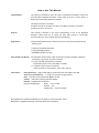
How to Use This Manual
Target Readers
This manual is intended for users who wish to understand the features of the RL78
microcontrollers EEPROM Emulation Library Pack 02 and to use the library in
designing and developing application systems.
The target products are as follows.
RL78/D1A, RL78/F12, RL78/F13, RL78/F14, RL78/G13, RL78/G14, RL78/G1A,
RL78/I1A, RL78/L13, RL78/L1C
Purpose
This manual is intended to give users understanding of how to use EEPROM
Emulation Library Pack 02 to rewrite the flash data memory in RL78-family
microcontrollers (i.e. write constant data by the application).
Organization
The RL78 EEPROM Emulation Library Pack 02 user’s manual is separated into the
following parts
:
• Overview of EEPROM Emulation
• Using EEPORM Emulation
• EEPROM Emulation Function
How to Read This Manual
It is assumed that the readers of this manual have general knowledge of electrical
engineering, logic circuits, and microcontrollers.
• To gain a general understanding of features
-> Read this manual in order of the table of contents.
• For details on the functions of the library
-> Refer to section 5, User Interface, of this user’s manual.
Conventions
Data significance:
Higher-order digits to the left and lower-order digits to the right
Active low representations:
Note:
xxx (overscore over pin and signal name)
Footnote for item marked with Note in the text.
Caution:
Information requiring particular attention
Remark:
Supplementary information
Numeral representation:
Binary ... xxxx or xxxxB
Decimal ... xxxx
Hexadecimal ... xxxxH or 0xXXXX
All trademarks and registered trademarks are the property of their respective owners.
EEPROM is a registered trademark of Renesas Electronics Corporation.
RL78 Family
EEPROM Emulation Library Pack02
Contents
Chapter 1 Overview ..................................................................................................... 7
1.1
Outline ....................................................................................................................................... 7
1.2
Target Devices .......................................................................................................................... 7
1.3
Definition of Terms .................................................................................................................. 7
Chapter 2 EEPROM Emulation ................................................................................... 9
2. 1 Specifications of EEPROM Emulation ...................................................................................... 9
2. 2 Outline of Function ..................................................................................................................... 9
2. 3 EEL architecture ....................................................................................................................... 11
2. 3. 1 System Structure ........................................................................................................ 11
2. 3. 2 EEL Pool ...................................................................................................................... 11
2. 3. 3 Structure of EEL Block ............................................................................................... 13
2. 3. 4 EEL Block Header ....................................................................................................... 14
2. 3. 5 Structure of Stored Data ............................................................................................ 15
2. 3. 6 EEL Block Overview ................................................................................................... 16
Chapter 3 EEL Functional Specifications ................................................................ 17
3.1
EEL Functions / Commands of the EEL_Execute Function .............................................. 17
3. 1. 1 EEL_CMD_STARTUP command [Startup processing] ........................................... 17
3. 1. 2 EEL_CMD_SHUTDOWN command [Shutdown processing] .................................. 17
3. 1. 3 EEL_CMD_REFRESH command [Refresh processing] .......................................... 17
3. 1. 4 EEL_CMD_FORMAT command [Format processing] ............................................. 18
3. 1. 5 EEL_CMD_WRITE command [Write processing] .................................................... 18
3. 1. 6 EEL_CMD_READ command [Read processing] ...................................................... 18
3. 1. 7 EEL_CMD_VERIFY command [Verify processing] .................................................. 18
3.2
State Transitions .................................................................................................................... 19
3.3
Basic Flowchart ...................................................................................................................... 21
3.4
Command Operation Flowchart ........................................................................................... 23
3.5
BGO(Back Ground Operation)function ........................................................................... 24
Chapter 4 Using EEPROM Emulation....................................................................... 25
4.1
Caution Points ........................................................................................................................ 25
4.2
Number of stored user data items and total user data size ............................................... 27
4.3
Initial Values to be set by User ............................................................................................. 28
Chapter 5 User Interface ........................................................................................... 31
5. 1 Request Structure (eel_request_t) Settings........................................................................... 31
5.1.1
User Write Access ...................................................................................................... 32
5.1.2
User Read Access ...................................................................................................... 32
5. 2 EEL Function Calls ................................................................................................................... 33
5. 3 Data Types ................................................................................................................................. 33
5. 4 EEL Function ............................................................................................................................. 34
FDL_Init ................................................................................................................................... 35
FDL_Open ............................................................................................................................... 36
FDL_Close............................................................................................................................... 37
EEL_Init ................................................................................................................................... 38
R01US0068EJ0100 Rev.1.00
Mar. 28, 2014
Page 5 of 53
RL78 Family
EEPROM Emulation Library Pack02
EEL_Open ............................................................................................................................... 39
EEL_Close............................................................................................................................... 40
EEL_Execute .......................................................................................................................... 41
EEL_Handler ........................................................................................................................... 45
EEL_GetSpace ........................................................................................................................ 46
EEL_GetVersionString........................................................................................................... 47
Chapter 6 Software Resources and Processing Time ............................................ 48
6. 1 Processing Time ....................................................................................................................... 48
6. 2 Software Resources ................................................................................................................. 50
6. 2. 1 Sections ....................................................................................................................... 52
Appendix A Revision History.................................................................................. 53
Major Changes in This Document .................................................................................................. 53
R01US0068EJ0100 Rev.1.00
Mar. 28, 2014
Page 6 of 53
RL78 Family
Chapter 1
Overview
EEPROM Emulation Library Pack02
Chapter 1 Overview
1.1
Outline
EEPROM emulation is a feature used to store data in the on-board flash memory in the same way as EEPROM.
During EEPROM emulation, the Data Flash library and EEPROM emulation library are used, and the data flash
memory is written to and read from.
The Data Flash library is a software library used to perform operations on the data flash memory. The EEPROM
emulation library is a software library used to execute EEPROM emulation from a user-created program. The Data
Flash library and EEPROM emulation library are placed in the code flash memory for use.
The EEPROM emulation library is free software to rewrite the data flash through the user program.
In this user’s manual, processing of the EEPROM emulation library includes processing of the Data Flash library.
Be sure to use this user’s manual together with the release note supplied with the package of this EEPROM
emulation library and the user’s manual for the target device.
1.2
Target Devices
For the latest device information, please contact our distributors or sales representatives.
1.3
Definition of Terms
The terms used in this manual are defined below.
• Pack
"Pack" is an identification name representing an EEPROM emulation library type. Use the pack corresponding to
your device.
• EEL
An abbreviation of the EEPROM Emulation library.
In this user’s manual, the RL78 EEPROM emulation library Pack02 is hereafter referred to as EEL.
• FDL
An abbreviation of the Data Flash library.
• FSL
An abbreviation of the Flash Self Programming library.
• EEL function
A generic term for the functions offered by the EEL.
R01US0068EJ0100 Rev.1.00
Mar. 28, 2014
Page 7 of 53
RL78 Family
Chapter 1
Overview
EEPROM Emulation Library Pack02
• FDL function
A generic term for the functions offered by the FDL.
• FSL function
A generic term for the functions offered by the FSL.
• Block number
A number which identifies a block of Flash memory.
•EEL Blocks
An abbreviation of blocks that the EEPROM emulation library accesses. In this user’s manual, EEPROM emulation
blocks are hereafter referred to as EEL blocks.
•CF
Code Flash
•DF
Data Flash
R01US0068EJ0100 Rev.1.00
Mar. 28, 2014
Page 8 of 53
RL78 Family
Chapter 2
EEPROM Emulation
Type 01 EEPROM Emulation Library Pack02
Chapter 2 EEPROM Emulation
2. 1 Specifications of EEPROM Emulation
By calling the EEL function provided by the EEL from a user-created program, use is possible without the
awareness of data flash memory operations.
For the EEL, a one-bye identifier (data ID: 1 to 64) is assigned by the user for each data item, and reading and
writing using any unit from 1 to 255 bytes are possible on an assigned identifier basis.(The EEL can handle up to 64
identifiers.)
Note that three or more continuous block area of data flash memory (recommended)
Note
are used to store the
data. These blocks are called EEL blocks. Data written by EEPROM emulation is divided into reference data and
user-specified data, and the reference data is written to the target blocks from the lower block address, while the
user data is written from the higher block address.
Note: At least two blocks are necessary for EEPROM emulation. When two blocks are specified, if a write error
occurs even once, only reading of normally written data is possible but writing is no longer possible. After
that, the two target blocks must be formatted when the EEL is used to write data. Written data is erased
completely. Since a contingency (such as voltage drop) may occur in the system, we recommend that you
specify at least three blocks.
2. 2 Outline of Function
The EEL provides basic read/write functions having the following features.
•
Up to 64 data items settable
•
A data size of 1 to 255 bytes settable
•
Supporting the back ground operation (BGO)
•
Consumption of memory for management data
(10 bytes per EEL block and 2 bytes per EEL block write data)
•
Reset resistance (EEL_CMD_WRITE, EEL_CMD_REFRESH)
•
Block rotation (averaging data flash use frequency)
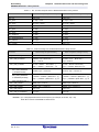
Renesas Electronics also provides RL78 EEPROM Emulation Library Pack 01 (EEL Pack01) as another EEL.
EEL consumes smaller amount of resource than EEL Pack01. Other functional differences are listed in the table
below. (For details of functions, see the RL78 Microcontroller EEPROM Emulation Library Pack 01 user’s manual
R01US0054EJ0102.)
R01US0068EJ0100 Rev.1.00
Mar. 28, 2014
Page 9 of 53
RL78 Family
Chapter 2
EEPROM Emulation
EEPROM Emulation Library Pack02
Item
User data length
Amount of stored user data
Note 1
Data ID range
Number of EEPROM emulation blocks
Note 2
Recommended user data size Note 1
EEL Pack01
EEL
1 to 255
1 to 255
1 to 255
1 to 64
1 to 255
1 to 64
4 to 255
3 to 255
980 x total number of blocks
1014/2 bytes
x 1/4 - 980/2 bytes
Enforce mode and TimeOut mode
Supported
Not supported
Back ground maintenance processing
Supported
Not supported
Can be set arbitrarily
Cannot be set arbitrarily
Supported
Not supported
Data ID number
Auto-checksum for data
Note1: The total size of user data must be within 1/2 of each block when all user data are written to an EEL
block. Therefore, the range used for the number of stored user data items differs depending on the size
of the stored user data. It is also necessary to consider the size of the reference data provided for each
data item for management use when determining the total size. For details about the number of stored
user data items and total size, see 4.2 Number of stored user data items and total user data size.
Note 2: EEL blocks cannot be set more than maximum number of blocks of on-board data flash memory.
R01US0068EJ0100 Rev.1.00
Mar. 28, 2014
Page 10 of 53
RL78 Family
Chapter 2
EEPROM Emulation
EEPROM Emulation Library Pack02
2. 3 EEL architecture
This chapter describes the EEL architecture required for the user to rewrite data flash (the EEL pool) by using the
EEL.
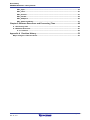
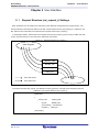
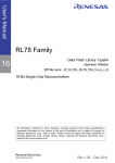
2. 3. 1 System Structure
The EEL offers interface for accessing the data flash area defined by the user. The arrows shown in the figure 2-1
below indicate the flow of processing.
Figure 2-1
System Structure
ユーザ・プログラム
Code Flash
User Program
EEL
Before using the EEL, the FDL must
FDL
be initialized.
(FDL_Init and FDL_Open function)
Data Flash
(EEL Pool)
2. 3. 2 EEL Pool
The EEL pool is a user-defined data flash area that is accessible by the EEL. The user program can access the
data flash only by using this EEL pool in the data flash via the EEL. The EEL pool size must be specified with the
number of blocks in the data flash of the target device. For the procedure to specify the number of blocks, see
section 4.3, Initial Values to be set by User.
The EEL pool is divided into 1024-byte blocks. Each block has a state which indicates the current usage of the
block.
State
Active
Description
Only a single EEL block is active at a time to store defined data.
The active block circulates in
data flash blocks allocated in the EEL pool.
Invalid
No data is stored in invalid blocks. EEL blocks are marked as invalid by the EEL or become
invalid in the case of erasure blocks.
Excluded
If functional operation failed and possibility of a data flash failure is clarified, the EEL excludes
the relevant block and the block is no longer used for EEPROM emulation.
R01US0068EJ0100 Rev.1.00
Mar. 28, 2014
Page 11 of 53
RL78 Family
Chapter 2
EEPROM Emulation
EEPROM Emulation Library Pack02
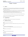
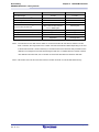
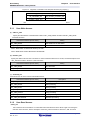
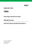
Figure 2-2 shows an exemplary pool configuration for a device with 8 KB data flash.
When no writable area is remaining in the active block (block 1 in the example) and data can no longer be stored
(failure in write command), a new active block is selected in a cyclic manner and the current valid data set is copied
to this new active block. This process is referred to as refresh. After the EEL_CMD_REFRESH command is
executed, the previous active block becomes invalid and only a single active block exists. Excluded blocks (like
block 7 in the example) are ignored during this process and not considered as candidates for the selection of the
next active block.
Figure 2-2
EEL pool structure
Data Flash Memory
physical
block
physical
block
physical
block
physical
block
physical
block
physical
block
physical
block
physical
block
0
1
2
3
4
5
6
7
EEL pool
EEL
block
0
EEL
block
1
EEL
block
2
EEL
block
3
EEL
block
4
EEL
block
5
EEL
block
6
EEL
block
7
I
A
I
I
I
I
I
X
A
active block
I
invalid block
X
excluded block
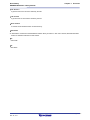
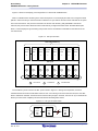
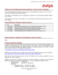
The overall life cycle of a block in the EEL pool is shown in Figure 2-3. During normal operation, the block
switches between active and invalid state. When an error occurs during an access to the EEL block, the error EEL
block is marked as excluded. This block will not enter the lifecycle again. However, the user can try to reanimate the
block by a format of the complete pool which also erases all existing data content.
Figure 2-3 Life cycle of an EEL block
invalid
block
active
block
excluded
block
I
A
X
format
R01US0068EJ0100 Rev.1.00
Mar. 28, 2014
Page 12 of 53
RL78 Family
Chapter 2
EEPROM Emulation
EEPROM Emulation Library Pack02
The EEL pool has the four states shown below.
Table 2-1
State
States of the EEL Pool
Description
Pool operational
This is the usual case during EEL operation. All commands are available and can be executed.
Pool full
Free space for data write is insufficient in the active block in use. This state indicates that a
refresh needs to be executed.
Pool exhausted
No continuously usable EEL block is left. (At least two blocks that are not excluded are
necessary for EEL operations.)
Pool inconsistent
There is a mismatch in the pool state and the data structure in the EEL block does not match
the user-set data structure. The EEL block is in the undefined state (e.g. no active block is
present).
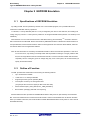
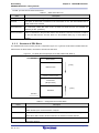
2. 3. 3 Structure of EEL Block
The detailed block structure used by the EEL is depicted in Figure 2-4. In general, an EEL block is divided into three
utilized areas: the block header, the reference area and the data area.
Figure 2-4
ELL Block Structure (Example of RL78/G13 Data Flash Block 0)
0xF1000
block header
growing
reference area
separator (erased 2 bytes)
erased area
(all bytes 0xFF)
growing
data area
0xF13FF
Table 2-2
Configuration of Each EEL Block
Name
Description
block header
The block header contains all block status information needed for the block management
within the EEL-pool. It has a fixed size of 8 bytes.
reference area
The reference area contains reference data which are required for the management of
data. When data is written, this area extends in the address increment direction.
data area
The data area contains user data. When data is written, this area extends in the address
decrement direction.
R01US0068EJ0100 Rev.1.00
Mar. 28, 2014
Page 13 of 53
RL78 Family
Chapter 2
EEPROM Emulation
EEPROM Emulation Library Pack02
Between reference area and data area, there is an erased area. With each EEL data update (i.e. the data is
written), this area is reduced successively. However, at least two bytes of space always remain between reference
area and data area for management and separation of these areas. This is indicated by the separator in Figure 2-4.
The EEL block header is detailed in 2.3.4, EEL Block Header, while the structure of data stored in the reference
and data area are described in Section 2.3.5, Structure of Stored Data.
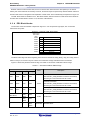
2. 3. 4 EEL Block Header
The structure of the block header is depicted in Figure 2-5. It is composed of eight bytes, four of which are
reserved for the system.
Figure 2-5
Structure of EEL block header
relative byte
index within
block
0x0000
A
0x0001
N
B
0xFF - N
0x0002
I
0x00
0x0003
X
0x00
0x0004
-
Reserved
0x0005
-
Reserved
0x0006
-
Reserved
0x0007
-
Reserved
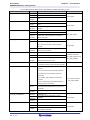
The block status flags start at the beginning of the block and include the A flag, B flag, I flag, and X flag, each of
which is one byte, for a total of 4 bytes of data. The combination of flags indicates the EEL block status.
Figure 2-5 shows the placement status of flags, and Table 2-3 shows the combination status of flags.
Table 2-3 Overviews of Block Status Flags
Block Status Flag
A Flag
B Flag
I Flag
State
Description
X Flag
Currently used block
0x01
0xFE
0xFF
0xFF
After the EEL_CMD_REFRESH command is executed,
the A flag of a new active block is set to 0x02.
Currently used block
0x02
0xFD
0xFF
0xFF
Active
After the EEL_CMD_REFRESH command is executed,
the A flag of a new active block is set to 0x03.
Currently used block
0x03
0xFC
0xFF
0xFF
After the EEL_CMD_REFRESH command is executed,
the A flag of a new active block is set to 0x01.
Data other than
the above
0xFF
--
other
than
0xFF
0xFF
--
other
than
0xFF
--
R01US0068EJ0100 Rev.1.00
Mar. 28, 2014
0xFF
Invalid
Excluded
Invalid block
Excluded block
Page 14 of 53
RL78 Family
Chapter 2
EEPROM Emulation
EEPROM Emulation Library Pack02
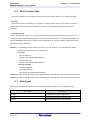
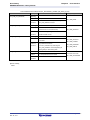
2. 3. 5 Structure of Stored Data
The structure of stored data when user data is written to an EEL block is shown in the figure below. A data is
composed of three parts: the start-of-record (SoR) field and the end-of-record (EoR) field and the data field. The
EEL descriptor table can be used to set data for use in the EEL. Each data is referred to by an identification number
(ID) and can have a size between 1 and 255 byte. (The exact specification of the format of the EEL descriptor can
be found in Section 4.3)
Each time data is written, stored data increase in the EEL block and multiple units of stored data exist in the EEL
block, but only the most recent stored data is referenced.
SoR and EoR build up the so-called reference data which is required for the management of the data. The
reference data and user data values are stored in different sections of the active block, namely the reference area
and the data area, respectively. Figure 2-6 shows the overview of the entire structure of stored data.
Figure 2-6
Structure of Stored Data
SoR
ID
EoR
0xFF - ID
reference data in EEL
block reference area
0x0000
Data
data field in EEL
block data area
Data Size - 1
Table 2-4
Description of Each Field of Data Area
Name
Description
SoR field
The one-byte SoR field contains the ID of data. This field indicates the start of write
(Start of Record)
processing. Data IDs 0x00 and 0xFF are not used to avoid patterns of erased cells.
EoR field
The one-byte EoR field contains a 0xFF – data ID value.
(End of Record)
This field indicates successful end of write processing. If writing does not end normally due
to a device reset or other reasons, the corresponding stored data is ignored by the EEL.
data field
The data field contains the user data. The size of user data is 1 to 255 bytes. When data of
two bytes or more is stored, the smallest address of the data is allocated to the smallest
address of the data field (as shown in figure 2-7)
Data is written to the EEL block in the order of SoR -> data field -> EoR. If write processing does not end
successfully, the immediately previous data becomes valid.
Note1: The total size of the reference consumed by each stored data is 2 bytes. This should be considered when
evaluating the free space in a block before writing the data through the EEL_GetSpace function.
Note2: No checksum is added to user data. If a checksum is needed, add it to user data and check through the
user program.
R01US0068EJ0100 Rev.1.00
Mar. 28, 2014
Page 15 of 53
RL78 Family
Chapter 2
EEPROM Emulation
EEPROM Emulation Library Pack02
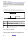
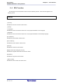
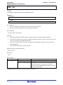
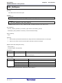
2. 3. 6 EEL Block Overview
Figure 2-7 shows an example of an EEL block that contains multiple units of stored data:
•Data ID 0x01 with size = 0x04,
•Data ID 0x02 with size = 0x01
•Data ID 0x03 is defined but not written here,
•Data ID 0x04 with size = 0x02
The data have been written in the sequence ID 0x01 -> ID 0x04 -> ID 0x02. In this example, the data with ID
0x03 has not been written yet.
Figure 2-7
Example of an Active EEL Block
relative byte
index within
block
0x0000
A = 0x02
0x0001
B = 0xFD
0x0002
I = 0xFF
0x0003
X = 0xFF
0x0004
reserved
0x0005
reserved
0x0006
reserved
0x0007
reserved
0x0008
SoR à ID = 0x01
0x0009
EoR à ~ID = 0xFE
0x000A
SoR à ID = 0x04
0x000B
EoR à ~ID = 0xFB
0x000C
SoR à ID = 0x02
0x000D
EoR à ~ID = 0xFD
0x000E
0x000F
…
…
…
…
…
…
…
…
block header
reference
area
separator (erased 2 bytes)
erased area
(all bytes 0xFF)
…
0x03F8
R01US0068EJ0100 Rev.1.00
Mar. 28, 2014
0x03F9
DATA(ID=0x02)[0]
0x03FA
DATA(ID=0x04)[0]
0x03FB
DATA(ID=0x04)[1]
0x03FC
DATA(ID=0x01)[0]
0x03FD
DATA(ID=0x01)[1]
0x03FE
DATA(ID=0x01)[2]
0x03FF
DATA(ID=0x01)[3]
data area
Page 16 of 53
RL78 Family
Chapter 3
EEL Functional Specifications
EEPROM Emulation Library Pack02
Chapter 3 EEL Functional Specifications
This chapter describes the functional specifications of the EEL required for the user to execute EEPROM
emulation.
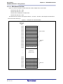
3.1
EEL Functions / Commands of the EEL_Execute Function
The table below summarizes the EEL functions offered by the EEL.
Table 3-1
EEL Functions
EEL function name
Functional overview
FDL_Init
Initializes the FDL.
FDL_Open
Preparation processing of FDL
FDL_Close
End processing of FDL
EEL_Init
Initializes the EEL
EEL_Open
Preparation processing of EEL
EEL_Close
End processing of EEL
EEL_Execute
Manipulates data flash with commands.
Command : EEL_CMD_STARTUP
EEL_CMD_WRITE
EEL_CMD_READ
EEL_CMD_REFRESH
EEL_CMD_VERIFY
EEL_CMD_FORMAT
EEL_CMD_SHUTDOWN
EEL_Handler
Controls the EEL while it is running.
EEL_GetSpace
Checks free space in the EEL block
EEL_GetVersionString
Obtains EEL version information.
With the EEL_Execute function, the following commands can be executed.
3. 1. 1 EEL_CMD_STARTUP command [Startup processing]
This checks the block status and sets the system to the EEPROM emulation start (started) state.
3. 1. 2 EEL_CMD_SHUTDOWN command [Shutdown processing]
Set the EEPROM emulation operation to the stopped state (opened).
3. 1. 3 EEL_CMD_REFRESH command [Refresh processing]
The latest stored data is copied from the active block (copy source block) to the next block (copy destination
block) in the EEL pool after the erase processing. This makes the copy destination block active.
R01US0068EJ0100 Rev.1.00
Mar. 28, 2014
Page 17 of 53
RL78 Family
Chapter 3
EEL Functional Specifications
EEPROM Emulation Library Pack02
3. 1. 4 EEL_CMD_FORMAT command [Format processing]
This initializes (erases) everything, including the data recorded in the EEL blocks. Be sure to use this command
before using EEPROM emulation for the first time.
3. 1. 5 EEL_CMD_WRITE command [Write processing]
Write the specified data to an EEL block.
3. 1. 6 EEL_CMD_READ command [Read processing]
Read the specified data from an EEL block.
3. 1. 7 EEL_CMD_VERIFY command [Verify processing]
This command performs internal verification to check signal levels of the active block.
R01US0068EJ0100 Rev.1.00
Mar. 28, 2014
Page 18 of 53
RL78 Family
Chapter 3
EEL Functional Specifications
EEPROM Emulation Library Pack02
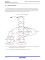
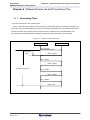
3.2
State Transitions
To use EEPROM emulation from a user-created program, it is necessary to initialize the EEL and execute
functions that perform operations such as reading and writing on EEL blocks. Figure 3-1 shows the overall state
transitions, and Figure 3-2 shows an operation flow for using basic features. When using EEPROM emulation,
incorporate EEPROM emulation into user-created programs by following this flow.
Figure 3-1
State transitions diagram
uninitialized
Reset or Power ON
FDL_Init()
↓
FDL_Open()
↓
EEL_Init()
FDL_Close()
closed
EEL_Close()
EEL_Open()
opened
EEL_CMD_FORMAT status:OK
status:ERROR
status:ERROR
EEL_CMD_STARTUP
EEL_CMD_SHUTDOWN
Startup executing
busy
Format executing
busy
EEL_CMD_SHUTDOWN
status:
ERROR
POOL_EXHAUSTED status:OK
ERROR Verify
EEL_CMD_STARTUP
EEL_CMD_FORMAT
started
exhausted
status:OK
status:ERROR
EEL_CMD_READ
EEL_CMD_VERIFY
EEL_CMD_WRITE
EEL_CMD_READ
EEL_CMD_REFRESH
EEL_CMD_VERIFY
status:OK
status:ERROR
status:
ERROR
POOL_EXHAUSTED
EEPROM command executing
busy
Note 1:
EEPROM command executing
busy
EEL_Close and EEL_Init can be called from every state. Please note however, that this interrupts any
EEL processing and can lead to unpredictable behavior.
Note 2:
Once the EEL_CMD_FORMAT command is started, be sure to finish it.
R01US0068EJ0100 Rev.1.00
Mar. 28, 2014
Page 19 of 53
RL78 Family
Chapter 3
EEL Functional Specifications
EEPROM Emulation Library Pack02
[Overview of state transitions diagram]
To use EEL to manipulate the data flash memory, it is necessary to execute the provided functions in order to
advance the processing.
(1) uninitialized
This is the state after turning the power on or resetting.
(2) closed
This is the state in which the data to perform EEPROM emulation is initialized by executing the FDL_Init,
FDL_Open, and EEL_Init functions (no ongoing operation to the data flash memory).
To execute FSL, STOP mode, or HALT mode processing after executing EEPROM emulation, execute
EEL_Close in the opened state to switch to the closed state.
(3) opened
This state is switched to by executing EEL_Open in the closed state and makes it possible to perform
operations on the data flash memory. It is not possible to execute FSL, STOP mode, or HALT mode
processing until EEL_Close is executed and the system switches to the closed state.
(4) started
This state is switched to by executing the EEL_CMD_STARTUP command in the opened state and
makes it possible to execute EEPROM emulation. Writes and reads that use EEPROM emulation are
performed in this state.
(5)exhausted
This state is made from the opened or started state when continuously usable EEL blocks have been
exhausted during command execution. In this state, only EEL_CMD_READ, EEL_CMD_VERIFY, and
EEL_CMD_SHUTDOWN commands are executable.
(6) busy
This is the state used when executing a specified command. The state that is switched to differ
depending on which command is executed and how it terminates.
R01US0068EJ0100 Rev.1.00
Mar. 28, 2014
Page 20 of 53
RL78 Family
Chapter 3
EEL Functional Specifications
EEPROM Emulation Library Pack02
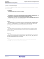
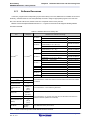
3.3
Basic Flowchart
Figure 3-2 below shows the basic procedure to perform read and write operations for the data flash by using the
EEL.
Figure 3-2
Basic Flowchart of EEL
start
(1) FDL_Init function
(2) FDL_Open function
(3) EEL_Init function
(4) EEL_Open function
(5) EEL_Execute function
EEL_CMD_STARTUP
(6) EEL_Execute function
EEL_CMD_WRITE
Yes
EEL_ERR_POOL_FULL?
No
(7) EEL_Execute function
(8) EEL_Execute function
EEL_CMD_READ
EEL_CMD_REFRESH
(9) EEL_Execute function
EEL_CMD_SHUTDOWN
(10) EEL_Close function
(11) FDL_Close function
end
Note 1: When using the EEPROM emulation for the first time, be sure to execute the EEL_CMD_FORMAT
command.
Note 2: Error processing is omitted in the above flowchart.
R01US0068EJ0100 Rev.1.00
Mar. 28, 2014
Page 21 of 53
RL78 Family
Chapter 3
EEL Functional Specifications
EEPROM Emulation Library Pack02
[Overview of basic operation flow]
(1)FDL initialization processing (FDL_Init)
Because it is necessary to initialize the FDL parameters (RAM) if using the EEL to access the data flash memory,
the FDL_Init function must be executed in advance. If FSL processing was executed after this initialization
finished, the initialization processing must be re-executed.
(2) FDL preparation processing (FDL_Open)
Set the Data Flash Control Register (DFLCTL) to the state where accessing the data flash memory is
permitted(DFLEN = 1).
(3) EEL initialization processing (EEL_Init)
Initialize the parameters (RAM) used by the EEL.
(4) EEPROM emulation preparation processing (EEL_Open)
Set the data flash memory to a state (opened) for which control is enabled to execute EEPROM emulation.
(5) EEPROM emulation execution start processing (EEL_Execute: EEL_CMD_STARTUP command)
Set the system to a state (started) in which EEPROM emulation can be executed.
(6) EEPROM emulation data write processing (EEL_Execute: EEL_CMD_WRITE command)
Write the specified data to an EEL block.
(7) EEPROM emulation data read processing (EEL_Execute: EEL_CMD_READ command)
Read the specified data from an EEL block.
(8) EEPROM emulation refresh processing (EEL_Execute: EEL_CMD_REFRESH command)
The latest stored data is copied from the active block (copy source block) to the next block (copy destination
block) in the EEL pool after the erase processing. This makes the copy destination block active
(9) EEPROM emulation execution stop processing (EEL_Execute: EEL_CMD_SHUTDOWN command)
Set the EEPROM emulation operation to the stopped state (opened).
(10) EEPROM emulation end processing (EEL_Close)
Set the data flash memory to a state (closed) for which control is disabled to stop EEPROM emulation.
(11) FDL end processing (FDL_Close)
Set the Data Flash Control Register (DFLCTL) to the state where accessing the data flash memory is inhibited
(DFLEN = 0).
R01US0068EJ0100 Rev.1.00
Mar. 28, 2014
Page 22 of 53
RL78 Family
Chapter 3
EEL Functional Specifications
EEPROM Emulation Library Pack02
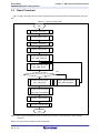
3.4
Command Operation Flowchart
The figure below shows the basic procedure to perform read and write operations for data flash by using the
EEL.
Figure 3-3
Command Operation Flowchart
Start
(1)EEL_Execute function
Busy
(2) Busy state check
(3) EEL_Handler function
Not busy
(4) Final state check
Abnormal end
Normal end
Normal end
Error
(1) EEL_Execute function
Perform operations for data Flash.
(2) Busy state check
Check status_enu of the request structure (eel_request_t). When status_enu is EEL_BUSY, continue the data
flash operation. If status_enu is other than EEL_BUSY, terminate the data flash operation with an error.
(3) EEL_Handler function
Control the EEL while it is running. By repeating the execution of the EEL_Handler function, continue the
data flash operation.
(4) Final state check
If the final state is EEL_OK, the operation ends normally. Otherwise, it will be terminated with an error.
R01US0068EJ0100 Rev.1.00
Mar. 28, 2014
Page 23 of 53
RL78 Family
Chapter 3
EEL Functional Specifications
EEPROM Emulation Library Pack02
3.5
BGO(Back Ground Operation)function
The EEL_Execute function starts command processing and then immediately returns the control to the user
program. This allows the user program to run during the data flash operation and so is called back ground operation
(BGO).
The data flash read or write command processing is started by executing the EEL_Execute function, and the
processing is continued and completed by executing the EEL_Handler function. For this reason, the EEL_Handler
function must be executed continuously until the processing is completed.
To see if the processing requested from the EEL_Execute function has been successfully completed, call the
EEL_Handler function from the user program and check the status of ongoing processing.
The EEL_CMD_SHUTDOWN command does not require calling of the EEL_Handler function. However, we
recommend that you follow the command operation flowchart shown in figure 3-3.
R01US0068EJ0100 Rev.1.00
Mar. 28, 2014
Page 24 of 53
RL78 Family
Chapter 4
Using EEPROM Emulation
EEPROM Emulation Library Pack02
Chapter 4 Using EEPROM Emulation
EEPROM emulation can store a maximum of 64
Note
data items each consisting of 1 to 255 bytes in the flash
memory by using three or more blocks (recommended) of flash memory.
EEPROM emulation can be executed by incorporating the EEL into a user-created program and executing that
program.
Note: For details about the number of user data items that can be stored, see 4.2 Number of stored user data
items and total user data size.
4.1
Caution Points
EEPROM emulation is achieved by using a feature for manipulating the on-board microcontroller data flash
memory. Therefore, it is necessary to note the following
Table 4-1
No
Points for Caution (1/2)
Caution Points
1
All EEL codes and constants must be placed in the same 64-Kbyte flash block.
2
Initialization by the FDL_Init function must be performed before the FDL_Open, FDL_Close, or any EEL
function is executed.
3
The EEL must be initialized by the EEL_Init function before any EEL function is executed.
4
The data flash memory cannot be read during data flash memory operation by the EEL.
5
Do not execute STOP mode or HALT mode processing while the EEPROM emulation is being used.
If it is necessary to execute STOP mode or HALT mode processing, be sure to execute all of the
processing up to and including the EEL_Close function and FDL_Close function to finish EEPROM
emulation.
6
The watchdog timer does not stop during the execution of the EEL.
7
The request structure (eel_request_t) must be placed at an even address.
8
Do not destroy the request structure (eel_request_t) during command execution.
9
Initialize the argument (RAM) that is used by the EEPROM emulation library function. When not initialized,
a RAM parity error is detected and the RL78 microcontroller might be reset. For a RAM parity error, refer
to the user’s manual of the target RL78 microcontroller.
10
All members of the request structure (eel_request_t) must be initialized once before a command is
executed. If any unused member exists in the request structure (eel_request_t), set a desired value for the
member. If any member is not initialized, the RL78 microcontroller may be reset due to a RAM parity error.
For details, see the User’s Manual: Hardware for the RL78 microcontroller in use.
11
The EEL does not support multitask execution. Do not execute the EEL functions during interrupt
processing.
R01US0068EJ0100 Rev.1.00
Mar. 28, 2014
Page 25 of 53
RL78 Family
Chapter 4
Using EEPROM Emulation
EEPROM Emulation Library Pack02
Table 4-2
Points for Caution (1/2)
No
Caution Points
12
After the FDL_Close and EEL_Close functions have been executed, the requested command and ongoing
command stop and cannot be resumed. Before calling the FDL_Close and EEL_Close functions, finish all
ongoing commands.
13
Before using the EEPROM emulation library, always close the FSL. Also, do not run the FSL while the
EEPROM emulation library is being used. When using the FSL, be sure to execute all of the processing up
to and including the EEL_Close function and FDL_Close function to finish EEPROM emulation.
When using EEPROM emulation after executing FSL processing, it is necessary to start processing from
the initializing function (the FDL_Init function).
14
Before starting the EEPROM emulation, be sure to start up the high-speed on-chip oscillator first. The
high-speed on-chip oscillator must also be activated when using the external clock.
15
In address above 0xFFE20 (0xFE20), do not place data buffer (argument) or stack which is used by
EEL functions and FDL functions.
16
When using data transfer controller (DTC) during EEPROM emulation, do not place RAM area used by
DTC in self-RAM and in address above 0xFFE20 (0xFE20).
17
Until EEPROM emulation is finished, do not corrupt RAM area (including self-RAM) used by EEPROM
emulation.
18
No checksum is added to user data. If a checksum is needed, add it to user data and check through the
user program.
19
When the FDL descriptor or EEL descriptor is changed, the EEPROM emulation can no longer be
executed. In that case, the EEL pool must be formatted by the EEL_CMD_FORMAT command in addition
to initialization of FDL and EEL. When adding data, however, the EEPROM emulation can be continuously
executed.
20
Do not operate the Data Flash Control Register (DFLCTL) during the execution of the EEL.
21
To use the data flash memory for EEPROM emulation, it is necessary to execute the
EEL_CMD_FORMAT command upon first starting up to initialize the data flash memory and make it
usable as EEPROM emulation blocks.
22
It is recommended that at least three blocks be provided in the data flash memory to use the EEL.
23
Do not destroy EEL blocks by the user program that uses other EELs or FDLs.
24
The EEL does not support multitask execution. When executing an EEL function on the OS, do not
execute in from two or more tasks.
25
About an operation frequency of RL78 microcontrollers and an operation frequency value set by the
initializing function (FDL_Init), be aware of the following points:
-When using a frequency lower than 4 MHz as an operation frequency of RL78 microcontrollers, only 1
MHz, 2 MHz and 3 MHz can be used (frequencies other than integer values like a 1.5 MHz cannot be
used). Also, set an integer value 1, 2, or 3 to the operation frequency value set by the initializingfunction.
- When using a frequency of 4 MHz or higher
Note1
as an operation frequency of RL78 microcontrollers, a
certain frequency can be used as an operation frequency of RL78 microcontrollers.
- This operation frequency is not the frequency of the high-speed on-chip oscillator.
Note 1: For a maximum frequency, see the target RL78 microcontroller user’s manual.
R01US0068EJ0100 Rev.1.00
Mar. 28, 2014
Page 26 of 53
RL78 Family
Chapter 4
Using EEPROM Emulation
EEPROM Emulation Library Pack02
4.2
Number of stored user data items and total user data size
The total size of user data that can be used in the EEPROM emulation is limited. The size required for writing all user data
to an EEL block must be within 1/2 of the block. Therefore, the number of stored data items that can be used differs
depending on the size of user data that is actually stored. The following shows how to calculate the size that can be used
when actually writing user data, as well as the total user data size.
[Maximum usable size of one block that can be used to write the user data]
Size of one block of data flash memory:
1024 bytes
Size required for EEPROM emulation block management:
8 bytes
Free space necessary as termination information (separator): 2 bytes
Maximum usable size of one block = 1024 bytes - 8 bytes - 2 bytes = 1014 bytes
[Maximum size and recommended size]
Data must be held in one block. Therefore, the maximum size is the maximum usable size of one block but the following
relational expression should be met. To enable all data to be updated at least once, we recommend that the data be within
the half size of the maximum usable size of one block.
Maximum size = the basic total user data size + maximum data size + 2 ≤ 1014
( Assumed that the largest data can be updated once after all data have been written.)
Recommended size = 1014 / 2
(Assumed that all data can be updated once after all data have been written.)
[Calculating the size for writing each user data item ]Note
Size of each written user data item = data size + reference data size (2 bytes)
Note: For details, see 2.3.5 Structure of Stored Data.
[Calculating the basic total user data size]
Basic total size = (user data 1 + 2) + (user data 2 + 2) ... + (user data n + 2)
R01US0068EJ0100 Rev.1.00
Mar. 28, 2014
Page 27 of 53
RL78 Family
Chapter 4
Using EEPROM Emulation
EEPROM Emulation Library Pack02
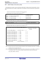
4.3
Initial Values to be set by User
As the initial values for the EEL, be sure to set the items indicated below. In addition, before executing the EEL, be sure to
execute the high-speed on-chip oscillator. The high-speed on-chip oscillator must also be activated when using the external
clock.
・Number of stored data items, and specific data IDs and data size
<Data flash library user include file (fdl_descriptor.h)>
Note 1,2
#define
FDL_SYSTEM_FREQUENCY
32000000
#define
FDL_WIDE_VOLTAGE_MODE
#define
FDL_POOL_BLOCKS
0
:(3) FDL pool size
#define
EEL_POOL_BLOCKS
4
:(4) EEL pool size
:(1) Operation frequency
:(2) Voltage mode
<EEPROM emulation library user include file (eel_descriptor.h)>
#define
EEL_VAR_NO
Note 1, 2
:(5) Number of stored data items
8
<EEPROM emulation library user program file (eel_descriptor.c)>
Note
2
__far const eel_u08 eel_descriptor[EEL_VAR_NO+2] =
:(6) Data size of the identifier
{
(data ID)
(eel_u08)(EEL_VAR_NO),
/* variable count
*/
¥
(eel_u08)(sizeof(type_A)),
/* id=1
*/
¥
(eel_u08)(sizeof(type_B)),
/* id=2
*/
¥
(eel_u08)(sizeof(type_C)),
/* id=3
*/
¥
(eel_u08)(sizeof(type_D)),
/* id=4
*/
¥
(eel_u08)(sizeof(type_E)),
/* id=5
*/
¥
(eel_u08)(sizeof(type_F)),
/* id=6
*/
¥
(eel_u08)(sizeof(type_X)),
/* id=7
*/
¥
(eel_u08)(sizeof(type_Z)),
/* id=8
*/
¥
(eel_u08)(0x00),
/* zero terminator
*/
¥
};
Note 1: The macros and macro names that are being used have common parameters with the EEL, so changes
should be made to numerical values only.
Note 2: After initializing the EEPROM emulation blocks (after executing the EEL_CMD_FORMAT command), do
not change the values. If the values are changed, reinitialize the EEL blocks (by executing the
EEL_CMD_FORMAT command).
R01US0068EJ0100 Rev.1.00
Mar. 28, 2014
Page 28 of 53
RL78 Family
Chapter 4
Using EEPROM Emulation
EEPROM Emulation Library Pack02
(1) Operation frequency
This sets an operation frequency which is used in RL78 microcontrollers.
Note1
The setting value is set to the FDL_Init frequency parameter by the following expressions (The frequency is
calculated by raising its decimals. The result calculated omits its decimals.).
Setting value of FDL_Init operation frequency = ((FDL_SYSTEM_FREQUENCY + 999999)/1000000)
Ex.1: When FDL_SYSTEM_FREQUENCY is 20000000 (20 MHz),
((20000000 + 999999)/10000000) = 20.999999 = 20
Ex.2: When FDL_SYSTEM_FREQUENCY is 4500000 (4.5 MHz),
((4500000 + 999999)/10000000) = 5.499999 = 5
Ex.3: When FDL_SYSTEM_FREQUENCY is 5000001 (5.000001 MHz),
((5000001 + 999999)/10000000) = 6.000000 = 6
Note1:
This setting is a value required to control data flash memory. This setting does not change the
operation frequency of RL78 microcontrollers. In addition, this operation frequency is not the
frequency of the high-speed on-chip oscillator.
(2) Voltage mode
Note 2
This sets the voltage mode of data flash memory.
Note 3
When FDL_WIDE_VOLTAGE_MODE is not defined: Full-speed mode
When FDL_WIDE_VOLTAGE_MODE is defined: Wide voltage mode
Note 2: The FDL_WIDE_VOLTAGE_MODE is commented out and not defined in the initial setting. To use
RL78 microcontrollers in the wide voltage mode, cancel the comment-out to define the mode.
Note 3: For details of the voltage mode, see the corresponding RL78 microcontrollers user’s manual.
(3) FDL pool size
Specify 0.
(4) EEL pool size
Note 4
The number of blocks in the data flash memory of the target device must be specified as the number of
blocks in the EEL pool.
Note 4: Specify 3 (3 blocks) or a greater value (recommended).
(5) Number of stored data items
Specify the number of data items to be used in the EEPROM emulation. A value of 1 to 64 can be set.
R01US0068EJ0100 Rev.1.00
Mar. 28, 2014
Page 29 of 53
RL78 Family
Chapter 4
Using EEPROM Emulation
EEPROM Emulation Library Pack02
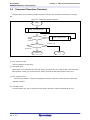
(6) Data size of each data identifier (data ID)
A table to define the data size of each identifier is provided below. This is called an EEL descriptor table.
The EEL can only add identifiers while the program is running. Data to be written must be registered in the
EEL descriptor table in advance.
Figure 4-1
EEL Descriptor Table (When there are eight different data)
__far const eel_u08 eel_descriptor [ Number of stored data items + 2 ]
EEL_VAR_NO
Byte size of data ID1
Byte size of data ID2
Byte size of data ID3
Byte size of data ID4
Byte size of data ID5
Byte size of data ID6
Byte size of data ID7
Byte size of data ID8
0x00
・EEL_VAR_NO
User-specified number of data items used in the EEL
・Byte size of Data IDx
User-specified size of user data (in bytes)
・Termination area (0x00)
Specify 0 as the termination information.
R01US0068EJ0100 Rev.1.00
Mar. 28, 2014
Page 30 of 53
RL78 Family
Chapter 5
User Interface
EEPROM Emulation Library Pack02
Chapter 5 User Interface
5. 1 Request Structure (eel_request_t) Settings
Basic operations such as reading from and writing to the data flash are performed by a single function. The
function transfers commands and data ID to the EEL via the request structure (eel_request_t). Furthermore, the
EEL state and error information are acquired via the request structure (eel_request_t).
In subsequent sections, write access to the request structure (eel_request_t) from the user is called user write
access, and read access to it from the user is called user read access.
Figure 5-1
Request Structure (eel_request_t)
User Program
address_pu08
identifier_u08
command_enu
status_enu
User write access
EEL
User read access
The request structure (eel_request_t) is defined in the eel_types.h file. It should not be changed by the user.
[Definition of the request structure (eel_request_t)]
typedef struct
{
__near eel_u08*
eel_u08
address_pu08;
identifier_u08;
eel_command_t command_enu;
eel_status_t
status_enu;
} eel_request_t;
R01US0068EJ0100 Rev.1.00
Mar. 28, 2014
Page 31 of 53
RL78 Family
Chapter 5
User Interface
EEPROM Emulation Library Pack02
Figure 5-2
Alignment of Variables of the Request Structure (eel_request_t)
__near eel_u08*
eel_u08 identifier_u08
address_pu08
eel_command_t command_enu;
eel_status_t status_enu;
bit0
5.1.1
Bit15
User Write Access
(1) address_pu08
Specify the start address of the data buffer used for EEL_CMD_WRITE command and EEL_CMD_READ
command execution.
Associated command (macro name)
Setting
Note 1
EEL_CMD_WRITE
Start address of the data buffer
EEL_CMD_READ
Start address of the data buffer
Note 2
Note 1: Buffer which contains data written by the user
Note 2: Buffer which contains data read from the data flash
(2) identifier_u08
Specify the data ID used for each command. For more information about how to do this, see the description of the
EEL_Execute function in section 5.4, EEL Functions.
Associated command (macro name)
Setting
EEL_CMD_WRITE
ID of write data
EEL_CMD_READ
ID of read data
(3) command_enu
Commands to be set in the common executable function.
Associated command (macro name)
Description
EEL_CMD_STARTUP
Startup processing
EEL_CMD_WRITE
Write processing
EEL_CMD_READ
Read processing
EEL_CMD_REFRESH
Refresh processing
EEL_CMD_VERIFY
Verify processing
EEL_CMD_FORMAT
Format processing
EEL_CMD_SHUTDOWN
Shutdown processing
5.1.2
User Read Access
- status_enu
EEL status and error information. For information about the status and errors which might occur during the
execution of the functions, see the description of the EEL_Execute function in section 5.4, EEL Functions.
R01US0068EJ0100 Rev.1.00
Mar. 28, 2014
Page 32 of 53
RL78 Family
Chapter 5
User Interface
EEPROM Emulation Library Pack02
5. 2 EEL Function Calls
This section describes how to call the EEL functions from a user program written in C or assembly language.
- C language
When an EEL function is called from a user program in C language in the same way as a normal C function is
called, the EEL function’s parameters are passed to the EEL as arguments and the required processing is
performed.
- Assembly language
Before calling an EEL function from a user program in assembly language, take necessary procedures (such as
setting parameters or return addresses) based on the function-calling rules for the C compiler package used by the
user as a development environment. The EEL function’s parameters are passed to the EEL as arguments and the
required processing is performed.
Remarks 1: To call the EEL functions offered by the EEL from a user program, you should define the following
standard header file and include it in that program:
C language
fdl.h: FDL header file
fdl_types.h: FDL definition setting header file
eel.h: EEL header file
eel_types.h: EEL definition setting header file
Assembly language
fdl.inc: FDL header file
eel.inc: EEL header file
eel_types.inc: EEL definition setting header file
Remarks 2: If an EEL function other than EEL_Init is called before EEL_Init is called, the correct operation is not guaranteed.
Remarks 3: If an EEL function other than FDL_Init is called before FDL_Init is called, the correct operation is not guaranteed.
5. 3 Data Types
Below are the data types of the parameters to be specified for calling the EEL functions offered by the EEL.
Macro name
Description
eel_u08
Unsigned 8-bit integers (unsigned char)
eel_u16
Unsigned 16-bit integers (unsigned short)
eel_u32
Unsigned 32-bit integers (unsigned long)
R01US0068EJ0100 Rev.1.00
Mar. 28, 2014
Page 33 of 53
RL78 Family
Chapter 5
User Interface
EEPROM Emulation Library Pack02
5. 4 EEL Function
The subsequent sections describe the EEL functions offered by the EEL. These functions appear in the
following format.
Name
[Function]
Describes the function overview of this function.
[Format]
<C language>
Describes the format to call this function from a user program described in the C language.
<Assembler>
Describes the format to call this function from a user program described in the Assembly language.
[Pre-conditions]
Describes the precondition of this function.
[Post-conditions]
Describes the post condition of this function.
[Cautions]
Describes the cautions of this function.
[Register status after calling this function]
Describes the register status after this function is called.
[Arguments]
Describes the argument of this function.
[Return values]
Describes the return values from this function.
R01US0068EJ0100 Rev.1.00
Mar. 28, 2014
Page 34 of 53
RL78 Family
Chapter 5
User Interface
EEPROM Emulation Library Pack02
FDL_Init
[Function]
FDL initialization processing
[Format]
<C language>
fdl_status_t __far FDL_Init(const __far fdl_descriptor_t* descriptor_pstr)
<Assembler>
CALL !FDL_Init or CALL !!FDL_Init
Remark Call this function by using ! if placing the FDL at 00000H to 0FFFFH or by using !! if not.
[Pre-conditions]
1.
The FSL and EEL processing must be either not executing or finished.
2.
The high-speed on-chip oscillator has been started up.
[Post-conditions]
Execute the FDL_Open function.
[Cautions]
1.
Be sure to execute this function when starting EEPROM emulation to make it possible to start accessing the
data flash memory.
2.
This function is mutually exclusive with the FSL. Before executing this function, be sure to end FSL. Also,
never use any FSL functions during EEPROM emulation.
3.
To use FSL after this function is executed, the RAM must be reinitialized, so always execute this function
when restarting the EEL.
4.
To execute this function again, always be sure to end EEL.
5.
The descriptor table used for this function cannot be modified. Be sure to use a defined descriptor table.
[Register status after calling this function]
Return Value : C
Corrupted registers: AX (argument), BC (argument)
[Arguments]
Argument
descriptor_pstr
Type
fdl_descriptor_t* (far)
Description
Pointer to the descriptor table
[Return values]
Type
fdl_status_t
Symbol Definition
Description
FDL_OK
Normal end
FDL_ERR_CONFIGURATION
Initialization error. The setting is incorrect. Or
high-speed on-chip oscillator does not run. Make sure
that the defined data has not been changed and the
high-speed on-chip oscillator has been started up.
Remark Assembly language return values are stored in register C.
R01US0068EJ0100 Rev.1.00
Mar. 28, 2014
Page 35 of 53
RL78 Family
Chapter 5
User Interface
EEPROM Emulation Library Pack02
FDL_Open
[Function]
FDL preparation processing
Set the Data Flash Control Register (DFLCTL) to the state where accessing the data flash memory is permitted
(DFLEN = 1).
[Format]
<C language>
void __far FDL_Open(void)
<Assembler>
CALL !FDL_Open or CALL !!FDL_Open
Remark Call this function by using ! if placing the FDL at 00000H to 0FFFFH or by using !! if not.
[Pre-conditions]
The FDL_Init function must have finisehed normally.
[Post-conditions]
Execute the EEL_Init function.
[Cautions]
None
[Register status after calling this function]
No registers are corrupted.
[Arguments]
None
[Return values]
None
R01US0068EJ0100 Rev.1.00
Mar. 28, 2014
Page 36 of 53
RL78 Family
Chapter 5
User Interface
EEPROM Emulation Library Pack02
FDL_Close
[Function]
FDL end processing
Set the Data Flash Control Register (DFLCTL) to the state where access to the data flash memory is inhibited
(DFLEN = 0). All ongoing EEL processing stop.
[Format]
<C language>
void __far FDL_Close(void)
<Assembler>
CALL !FDL_Close or CALL !!FDL_Close
Remark Call this function by using ! if placing the FDL at 00000H to 0FFFFH or by using !! if not.
[Pre-conditions]
The FDL_Init, FDL_Open, EEL_Init, EEL_Open, and EEL_Close functions must have finished normally.
[Post-conditions]
None
[Cautions]
None
[Register status after calling this function]
No registers are corrupted.
[Arguments]
None
[Return values]
None
R01US0068EJ0100 Rev.1.00
Mar. 28, 2014
Page 37 of 53
RL78 Family
Chapter 5
User Interface
EEPROM Emulation Library Pack02
EEL_Init
[Function]
Processing to initialize the RAM used for EEPROM emulation
[Format]
<C language>
eel_status_t __far EEL_Init (void)
<Assembler>
CALL !EEL_Init or CALL !!EEL_Init
Remark Call this function by using ! if placing the EEL at 00000H to 0FFFFH or by using !! if not.
[Pre-conditions]
1.
The FSL and the EEL processing must be either not executing or finished.
2.
The FDL_Init and FDL_Open function must have finished normally.
[Post-conditions]
Execute the EEL_Open function.
[Cautions]
1.
When starting EEPROM emulation, always execute this function to initialize the RAM to be used.
2.
This function is mutually exclusive with FSL. Before executing this function, be sure to close FSL. Also, never
use any FSL functions during EEPROM emulation.
3.
To use FSL after this function is executed, the RAM must be reinitialized, so always execute this function
when restarting EEL.
4.
To execute this function again, always close EEL.
[Register status after calling this function]
Return values: C
[Arguments]
None
[Return values]
Type
eel_status_t
Symbol Definition
Description
EEL_OK
Normal end
EEL_ERR_CONFIGURATION
Initialization error. The EEL cannot be executed with the
values set by the FDL_Init and EEL_Init functions.
Check the current setting referring to section 4.3, Initial
Values to be set by User.
Remark Assembly language return values are stored in register C.
R01US0068EJ0100 Rev.1.00
Mar. 28, 2014
Page 38 of 53
RL78 Family
Chapter 5
User Interface
EEPROM Emulation Library Pack02
EEL_Open
[Function]
EEPROM emulation preparation processing
This function makes the EEPROM emulation executable.
[Format]
<C language>
void
__far EEL_Open(void)
<Assembler>
CALL !EEL_Open or CALL !!EEL_Open
Remark Call this function by using ! if placing the EEL at 00000H to 0FFFFH or by using !! if not.
[Pre-conditions]
1. The FDL_Init, FDL_Open, and EEL_Init functions must have finished normally.
2. If EEPROM emulation was executed, the processing up to EEL_Close and FDL_Close function must be
executed to stop the EEPROM Emulation processing.
[Post-conditions]
None
[Cautions]
After the EEL_Open function is executed and the EEPROM emulation has been transitioned to the opened state,
the FSL cannot be executed. In addition, STOP mode and HALT mode cannot be executed. To execute the FSL,
STOP mode, or HALT mode, execute the EEL_Close and FDL_Close functions to transition the EEPROM
emulation to the uninitialized state.
[Register status after calling this function]
No registers are corrupted.
[Arguments]
None
[Return values]
None
R01US0068EJ0100 Rev.1.00
Mar. 28, 2014
Page 39 of 53
RL78 Family
Chapter 5
User Interface
EEPROM Emulation Library Pack02
EEL_Close
[Function]
EEPROM emulation end processing
This function makes the EEPROM emulation unexecutable.
[Format]
<C language>
void
__far EEL_Close(void)
<Assembler>
CALL !EEL_Close or CALL !!EEL_Close
Remark Call this function by using ! if placing the EEL at 00000H to 0FFFFH or by using !! if not.
[Pre-conditions]
If EEPROM emulation was executed, the EEL_CMD_SHUTDOWN command must be used to set EEPROM
emulation to the stopped state (the opened state).
[Post-conditions]
Execute the FDL_Close function to exit the EEPROM emulation.
[Cautions]
None
[Register status after calling this function]
No registers are corrupted.
[Arguments]
None
[Return values]
None
R01US0068EJ0100 Rev.1.00
Mar. 28, 2014
Page 40 of 53
RL78 Family
Chapter 5
User Interface
EEPROM Emulation Library Pack02
EEL_Execute
[Function]
EEPROM emulation execution function
Each type of processing for performing EEPROM emulation operations is specified for this function as an
argument in the command format, and the processing is executed.
[Format]
<C language>
void __far EEL_Execute(__near eel_request_t* request_pstr);
<Assembler>
CALL !EEL_Execute or CALL !!EEL_Execute
Remark Call this function by using ! if placing the EEL at 00000H to 0FFFFH or by using !! if not.
[Pre-conditions]
The FDL_Init, FDL_Open and EEL_Init, EEL_Open functions must have finished normally.
[Post-conditions]
1.
While status_enu of the request structure (eel_request_t) is EEL_BUSY, execute the EEL_Handler function
repeatedly.
2.
The EEL_Execute function starts command processing and then immediately returns the control to the user
program. The command processing is continued by executing the EEL_Handler function. Therefore, the
EEL_Handler function must be executed continuously until the command processing is completed.
[Cautions]
None
[Register status after calling this function]
Corrupted register: AX (argument)
[Arguments]
Argument
request_pstr
Type
Description
eel_request_t* (near)
Pointer to the request structure (eel_request_t)
eel_request_t Details
Member
eel_request_t.address_pu08
Type
Description
eel_u08 *
Pointer to the data buffer for storing write and read
(near)
data
eel_request_t.identifier_u08
eel_u08
Parameter for setting command to be executed
eel_request_t.command_enu
eel_command_t
Command to be executed
eel_request_t.status_enu
eel_status_t
Command execution status
Note
Note: Specify this parameter only for a command that requires the parameter. Set up the data buffer size according
to the byte sizes of the write and read data.
R01US0068EJ0100 Rev.1.00
Mar. 28, 2014
Page 41 of 53
RL78 Family
Chapter 5
User Interface
EEPROM Emulation Library Pack02
Execution Commands (eel_command_t)
Command
Description
This checks the block status and sets the system to the EEPROM emulation start
EEL_CMD_STARTUP
(started) state. If two active blocks exist, the incorrect block is changed to an
invalid block.
Be sure to execute this command before executing commands other than the
EEL_CMD_FORMAT command and make sure that the command finishes normally.
EEL_CMD_WRITE
Note 1
This writes the specified data to the EEL blocks.
* The following arguments must be specified prior to execution.
・address_pu08:Specifies the start address of the RAM area where the write data
is stored.
・identifier_u08: Specifies the data ID of the write data.
EEL_CMD_READ
Note 1
This reads the specified data from the EEL blocks.
*The following arguments must be specified prior to execution.
・address_pu08:Specifies the start address of the RAM area where the read data
is stored.
・identifier_u08:Specifies the data ID of the read data.
EEL_CMD_VERIFY
Note 1,2
This performs internal verification to check signal levels of the active block. This
command verifies whether signal levels of flash memory cells are appropriate or
not.
Note1,3
EEL_CMD_REFRESH
This copies the latest stored data from the active EEL block (copy source block)
to the next block (copy destination block) in the EEL pool after the erase
processing. This makes the copy destination block active.
EEL_CMD_FORMAT
This initializes (erases) everything, including the data recorded in the EEL
blocks. Be sure to use this command before using EEPROM emulation for the
first time. Furthermore, use this command to initialize the entire blocks when an
error (such as no active block) has occurred in EEL blocks or when modifying
values in the descriptor table (unchangeable fixed values).
Because EEPROM emulation switches to the stopped state (opened) regardless
of the results after the processing finishes, execute the EEL_CMD_STARTUP
command to continue using EEPROM emulation.
Note1
EEL_CMD_SHUTDOWN
This sets EEPROM emulation to the stopped state (opened).
Note 1: Do not execute this command until the EEL_CMD_STARTUP command has finished normally.
Note 2: This command is not used to perform processing for reading written data and compare it. To compare
written data, use the EEL_Execute (EEL_CMD_READ) function through the user program.
Note 3: The erase processing is performed by executing the EEL_CMD_REFRESH command.
R01US0068EJ0100 Rev.1.00
Mar. 28, 2014
Page 42 of 53
RL78 Family
Chapter 5
User Interface
EEPROM Emulation Library Pack02
Command Execution statuses of EEL_Execute/EEL_Handler (eel_status_t) (1/2)
Command Execution Status
EEL_OK
Category
Description
Meaning
Normal end
Cause
None
Action to
None
Corresponding Commands
All commands
be taken
EEL_BUSY
Meaning
A command is being executed.
Cause
None
Action to
Keep calling EEL_Handler function until the status
be taken
changes.
Meaning
Pool full error
Cause
There is no area that can be used to write the data.
Action to
Execute EEL_CMD_REFRESH command and
be taken
restart writing data.
Meaning
Initialization error
Cause
The FDL_Init, FDL_Open, EEL_Init, and
All commands
EEL_ERR_POOL_FULL
EEL_CMD_WRITE
EEL_ERR_INITIALIZATION
EEL_Open functions have not been finished
All commands
normally.
EEL_ERR_ACCESS_LOCKED
Action to
Normally finish the FDL_Init, FDL_Open, EEL_Init,
be taken
and EEL_Open functions.
Meaning
EEPROM emulation lock error
Cause
EEPROM emulation cannot be executed.
Action to
Make sure that the EEL_CMD_STARTUP
be taken
command has finished normally.
Commands other than
EEL_CMD_UNDEFINED
EEL_CMD_FORMAT
Command error
A command that does not exist has been specified.
EEL_ERR_VERIFY
EEL_CMD_STARTUP and
Meaning
--When the EEL_CMD_STARTUP command was
executed:
An error occurred during the internal verification
processing for the block header or the finally
written data.
When the EEL_CMD_VERIFY command was
executed:
EEL_CMD_STARTUP
EEL_CMD_VERIFY
An error occurred during the internal verification
processing for the active block.
Cause
Some signal levels of flash memory cells were not
appropriate.
Action to
Execute the EEL_CMD_REFRESH command.
be taken
EEL_ERR_PARAMETER
Meaning
Parameter error
Cause
An incorrect command parameter has been
Action to
Revise the specified parameter.
specified.
All commands
be taken
EEL_ERR_REJECTED
R01US0068EJ0100 Rev.1.00
Mar. 28, 2014
Meaning
Reject error
Cause
A different command is being executed.
Action to
Call the EEL_Handler function to terminate
be taken
the ongoing command.
All commands
Page 43 of 53
RL78 Family
Chapter 5
User Interface
EEPROM Emulation Library Pack02
Command Execution statuses of EEL_Execute/EEL_Handler (eel_status_t) (2/2)
Command Execution Status
EEL_ERR_NO_INSTANCE
EEL_ERR_POOL_INCONSISTENT
Category
Description
Meaning
No-write-data error
Cause
The specified identifier data has not been written.
Action to
Write data to the identifier specified using the
be taken
EEL_CMD_WRITE command.
Meaning
EEL block inconsistency error
Cause
An EEL block has the undefined state (such as
EEL_CMD_READ
because there are no active blocks).
EEL_ERR_POOL_EXHAUSTED
Corresponding Commands
Action to
Execute the EEL_CMD_FORMAT command to
be taken
initialize the EEL blocks.
Meaning
EEL block exhaustion error
Cause
There are no more EEL blocks that can be used
to continue.
Action to
Stop EEPROM emulation.
be taken
You can try restoration by executing the
EEL_CMD_STARTUP
EEL_CMD_STARTUP
EEL_CMD_FORMAT
EEL_CMD_REFRESH
EEL_CMD_WRITE
EEL_CMD_FORMAT command (erasing all
existing data) or read existing data.
EEL_ERR_INTERNAL
Meaning
Internal error
Cause
An unexpected error has occurred.
Action to
Check the device state.
Commands other than
EEL_CMD_SHUTDOWN
be taken
[Return values]
None
R01US0068EJ0100 Rev.1.00
Mar. 28, 2014
Page 44 of 53
RL78 Family
Chapter 5
User Interface
EEPROM Emulation Library Pack02
EEL_Handler
[Function]
Continuous EEPROM emulation execution processing
This function continues executing the EEPROM emulation processing specified for the EEL_Execute function.
[Format]
<C language>
void __far EEL_Handler(void);
<Assembler>
CALL !EEL_Handler or CALL !!EEL_Handler
Remark Call this function by using ! if placing the EEL at 00000H to 0FFFFH or by using !! if not.
[Pre-conditions]
1.
The FDL_Init, FDL_Open, and EEL_Init,EEL_Open functions must have finished normally.
2.
The EEL_Execute function should execute
Note
, and status_enu of the request structure (eel_request_t)
should be EEL_BUSY.
Note: Execution of the EEL_CMD_SHUTDOWN command does not need execution of the EEL_Handler function.
However, we recommend that you follow the command operation flowchart shown in figure 3-3.
[Post-conditions]
While status_enu of the request structure (eel_request_t) is EEL_BUSY, execute this function repeatedly. If the
EEL_Handler function is executed while no command is executed, status_enu of of the request structure
(eel_request_t) is not updated.
[Cautions]
The command execution status of the EEL_Handler function is set for the ”eel_request_t* request” used as an
argument of the EEL_Execute function. Therefore, when using the EEL_Handler function, do not free the
“eel_request_t* request” variable. For the execution state of the command specified by the EEL_Handler function,
see the list of the EEL_Execute/EEL_Handler command execution state (eel_status_t)
[Register status after calling this function]
No registers are corrupted.
[Arguments]
None
[Return values]
None
R01US0068EJ0100 Rev.1.00
Mar. 28, 2014
Page 45 of 53
RL78 Family
Chapter 5
User Interface
EEPROM Emulation Library Pack02
EEL_GetSpace
[Function]
This obtains the free EEL block space.
[Format]
<C language>
eel_status_t __far EEL_GetSpace(__near eel_u16* space_pu16)
<Assembler>
CALL !EEL_GetSpace or CALL !!EEL_GetSpace
Remark Call this function by using ! if placing the EEL at 00000H to 0FFFFH or by using !! if not.
[Pre-conditions]
The FDL_Init,FDL_Open,EEL_Init, and EEL_Open functions, and theEEL_Execute
function(EEL_CMD_STARTUP command ) must have finished normally.
[Post-conditions]
None
[Cautions]
1.
When the EEL pool has been exhausted, 0 is always returned to indicate that there is no free space.
2.
When an error value is returned, the free space information remains unchanged.
[Register status after calling this function]
Return value: C
Corrupted register: AX (argument)
[Arguments]
Type
Argument
space_pu16
eel_u16* (near)
Description
The address at which the free space information of the current
active block is input
[Return values]
Type
eel_status_t
Symbol Definition
Description
EEL_OK
Normal end
EEL_ERR_INITIALIZATION
EEL_Init has not been executed.
EEL_ERR_ACCESS_LOCKED
The EEL_CMD_STARTUP command has not finished normally.
EEL_ERR_REJECTED
A command is being executed.
Remark Assembly language return values are stored in register C.
R01US0068EJ0100 Rev.1.00
Mar. 28, 2014
Page 46 of 53
RL78 Family
Chapter 5
User Interface
EEPROM Emulation Library Pack02
EEL_GetVersionString
[Function]
This obtains the version information of the EEL.
[Format]
<C language>
__far eel_u08* __far EEL_GetVersionString(void)
<Assembler>
CALL !EEL_GetVersionString or CALL !!EEL_GetVersionString
Remark Call this function by using ! if placing the EEL at 00000H to 0FFFFH or by using !! if not.
[Pre-conditions]
None
[Post-conditions]
None
[Cautions]
None
[Register status after calling this function]
None
[Arguments]
None
[Return values]
Type
eel_u08*
(far)
Description
The address at which the version information of the EEL is input
(24-bit address area)
Example: For EEPROM emulation library Pack02 V1.00 (ASCII code)
“ERL78T02R110_GVxxx”
Version information : V110→V1.10
Corresponding tool : Renesas Electronics version
Type name : Type02
Corresponding device : RL78
Target library : EEL
R01US0068EJ0100 Rev.1.00
Mar. 28, 2014
Page 47 of 53
RL78 Family
Chapter 6
Software Resources and Processing Time
EEPROM Emulation Library Pack02
Chapter 6 Software Resources and Processing Time
6. 1 Processing Time
This section describes the EEL processing time.
Figure 6-1 shows the concept of EEL function response time and total processing time. The total processing time in the
figure is the case of successful completion and does not include the processing time in the case of abnormal end (such as
incorrect input data or error). Delay time due to execution of the EEL_Handler function is not included either. If the
EEL_Handler function calling interval time is extended, the maximum total processing time may be exceeded.
Figure 6-1
Overview of Processing Time
User Program
EEL
EEL_Execute
Response
Time
Status = BUSY
EEL_Handler
Status = BUSY
Total Processing Time
EEL_Handler
Status = BUSY
EEL_Handler
Status = OK
R01US0068EJ0100 Rev.1.00
Mar. 28, 2014
Page 48 of 53
RL78 Family
Chapter 6
Software Resources and Processing Time
EEPROM Emulation Library Pack02
Table 6-1
EEL Function Response Time of EEPROM Emulation Library Pack02
Functions
MAX time(Full Speed Mode)
MAX time(Wide Voltage Mode)
FDL_Init
1199 / fcpu
1199 / fcpu
FDL_Open
27 / fcpu + 14us
27 / fcpu + 14us
FDL_Close
836 / fcpu + 444us
791 / fcpu + 969us
EEL_Init
3268 / fcpu
3268 / fcpu
EEL_Open
14 / fcpu
14 / fcpu
EEL_Close
17 / fcpu
17 / fcpu
EEL_GetSpace
47 / fcpu
47 / fcpu
EEL_GetVersionString
14 / fcpu
14 / fcpu
EEL_Execute
320 / fcpu
320 / fcpu
EEL_Handler
4582 / fcpu
4582 / fcpu
Table 6-2
Functions
Total Processing Time of EEPROM Emulation Library Pack 02
MAX time(Full Speed Mode)
MAX time(Wide Voltage Mode)
EEL_Execute / EEL_Handler
EEL_CMD_STARTUP
EEL_CMD_FORMAT
( 280530 + 235 * Block Num )
( 277604 + 235 * Block Num )
/ fcpu + 1612 us
/ fcpu + 8798 us
( 67102 + 288981 * Block Num
/ fcpu + ( 266627 * Block Num
)
) us
( 67102 + 256218 * Block Num )
/ fcpu + ( 303359 * Block Num ) us
EEL_CMD_REFRESH
5163828 / fcpu + 774424 us
5072479 / fcpu + 1421917 us
( 1554000 + 7538406 * (Block Num - 1) )
( 1554000 + 7355752 * (Block Num - 1) )
/ fcpu + ( 1548404 * (Block Num - 1) ) us
/ fcpu + ( 2842866 * (Block Num - 1) ) us
EEL_CMD_VERIFY
30869 / fcpu + 4126 us
19605 / fcpu + 29754 us
EEL_CMD_WRITE
303387 / fcpu + 111858 us
289240 / fcpu + 253342 us
EEL_CMD_READ
5102 / fcpu
5102 / fcpu
EEL_CMD_SHUTDOWN
219 / fcpu
219 / fcpu
1. Finished normally
EEL_CMD_REFRESH
2. REFRESH processing
failed until Block Num -1
Remarks
fcpu: CPU/peripheral hardware clock frequency (for example, at 20 MHz, fcpu = 20)
Block Num: Number of EEPROM emulation blocks
R01US0068EJ0100 Rev.1.00
Mar. 28, 2014
Page 49 of 53
RL78 Family
Chapter 6
Software Resources and Processing Time
EEPROM Emulation Library Pack02
6. 2
Software Resources
In the EEL, program areas corresponding to parts of the library to be used, RAM areas for variables to be used in
the library, and RAM areas for work area (self-RAM) are used to assign an appropriate program to the user area.
Also, since the FDL will be used, the EEL must have a separate area for use by the FDL.
Tables 6-3 and 6-4 list required software resources
Note 1, 2
. Figures 6-2 and 6-3 show the images of allocating software
resources to the RAM.
Table 6-3 Software Resources Used by EEL
Item
Restrictions on Allocation and UsageNote1,2
Size(byte)
RAM 4KB
ROM 64KB
FEF00H to FF2FFH
RAM 16KB
ROM 256KB
FBF00H to FC2FFH
RL78/F12
RAM 4KB
ROM 64KB
FEF00H to FF2FFH
RL78/F13
RAM 4KB
ROM 64KB
( R5F10AmE (m = 6, A, B, G, L) )
FEF00H to FF2FFH
RAM 8KB
FDF00H to FE2FFH
RL78/D1A
RAM 8KB
ROM 96KB
( R5F10PmF (m = G, L, M) )
FDF00H to FE2FFH
RAM 20KB
ROM 256KB
FAF00H to FB2FFH
RAM 4KB
ROM 64KB
FEF00H to FF2FFH
RAM 20KB
( R5F100xJ
ROM 256KB
( x = F, G, J, L, M, P) )
FAF00H to FB2FFH
RAM 32KB
ROM 512KB
F7F00H to F82FFH
RAM 5.5KB
ROM 48KB
FE900H to FECFFH
RAM 5.5KB
ROM 64KB
FE900H to FECFFH
RAM 24KB
ROM 256KB
F9F00H to FA2FFH
RL78/G1A
RAM 4KB
ROM 64KB
FEF00H to FF2FFH
RL78/I1A
RAM 4KB
ROM 64KB
FEF00H to FF2FFH
RL78/L13
RAM 8KB
ROM 128KB
FDF00H to FE2FFH
RAM 16KB
ROM 192KB
FBF00H to FC2FFH
RAM 16KB
ROM 256KB
FBF00H to FC2FFH
RL78/F14
Note3
Self-RAM
Note3
0 to 1024
RL78/G13
RL78/G14
RL78/L1C
ALL Note 1,2
Stack
Products other than the above
Contact us.
80
Data buffer
Note4
1 to 255
Request Structure
SADDR RAM work
area
SADDR : 3
(fdl:2)
(eel:1)
3400
(fdl:600)
(eel:2800)
Data table
3 to 68
Fixed-parameter area
(default)
EEL Blocks
Can be allocated to a RAM area other than the self-RAM and the area from FFE20H
to FFEFFH
5
Library size
Note
ROM128KB
14
(fdl:10)
(eel:2)
3,072 or more
(at least 3
blocks)
Can be allocated to a short-addressing RAM area
Can be allocated to any program area other than the self-RAM and the area from
FFE20H to FFEFFH (ROM is recommended)
Only data flash memory can be used.
1: Please contact about products added after this document is issued.
R01US0068EJ0100 Rev.1.00
Mar. 28, 2014
Page 50 of 53
RL78 Family
Chapter 6
Software Resources and Processing Time
EEPROM Emulation Library Pack02
2: The RL78/G12, L12 and G1C product does not support the EEL
3: An area used as the working area by the EEL is called self-RAM in this manual and the release note. The
self-RAM requires no user setting because it is an area that is not mapped and automatically used at
execution of the EEL (previous data is discarded). When the EEL is not used, the self-RAM can be used as
a normal RAM space.
For the RL78 microcontroller with self-RAM, the chapter of "memory space" in the user's manual of the
RL78 microcontroller has a note on an area (self-RAM) whose usage is prohibited during self-programming.
If the above table does not include the target RL78 microcontroller, refer to the user's manual of the target
RL78 microcontroller.
4: The data buffer is used as the working area for EEL internal processing or the area where the data to be
set is allocated in the EEL_Execute function. The required size depends on the function to be used.
Table 6-4
Function Name
FDL_Init
Data Buffer Size Used by EEL Functions
Bytes
0
FDL_Open
0
Function Name
Bytes
EEL_Close
0
EEL_Execute
Note
0 to 255
Note
0 to 255
FDL_Close
0
EEL_Handler
EEL_Init
0
EEL_GetSpace
2
EEL_Open
0
EEL_GetVersionString
0
Note: An additional 5-byte area is used by the request structure.
Figure 6-2
Arrangement Example of Self-RAM and Addresses FFE20H to FFEFFH
(RL78/G13: product with 4-Kbyte RAM and 64-Kbyte ROM)
R01US0068EJ0100 Rev.1.00
Mar. 28, 2014
Page 51 of 53
RL78 Family
Chapter 6
Software Resources and Processing Time
EEPROM Emulation Library Pack02
Figure 6-3
Arrangement Example of Addresses FFE20H to FFEFFH
(RL78/G13: product with 2-Kbyte RAM and 32-Kbyte ROM)
6. 2. 1 Sections
Functions, constants, and variables to be used are allocated to specified sections in the EEL and FDL.
The following table lists sections defined by the EEL and FDL.
Table 6-5
Section name
Sections Used in the EEL/FDL
Description
FDL_CODE
FDL’s code section that contains FDL programs.
FDL_SDAT
FDL’s variable data section that contains variable data used in the FDL.
Place this section in the short addressing RAM area.
FDL_CNST
FDL’s constant data section that contains constant data used in the FDL.
EEL_CODE
EEL’s code section that contains EEL programs.
EEL_SDAT
EEL’s variable data section that contains variable data used in the EEL.
Place this section in the short addressing RAM area.
EEL_CNST
EEL’s constant data section that contains constant data used in the EEL.
R01US0068EJ0100 Rev.1.00
Mar. 28, 2014
Page 52 of 53
RL78 Family
Appendix A Revision History
EEPROM Emulation Library Pack02
Appendix A
Revision History
Major Changes in This Document
Page
All
Change/Addition
Newly created
Type
-
Remark: "Type" in the above table indicates types of revisions.
(a): Correction of erroneous description
(b): Addition/change to specifications
(c): Addition/change to description or notes
(d): Addition/change to the package, order name, or classification
(e): Addition/change to related documents
R01US0068EJ0100 Rev.1.00
Mar. 28, 2014
Page 53 of 53
奥付
RL78 Family User’s Manual
EEPROM Emulation Library Pack 02
Publication Date:
Mar 28, 2014
Rev.1.00
Published by:
Renesas Electronics Corporation
http://www.renesas.com
SALES OFFICES
Refer to "http://www.renesas.com/" for the latest and detailed information.
Renesas Electronics America Inc.
2801 Scott Boulevard Santa Clara, CA 95050-2549, U.S.A.
Tel: +1-408-588-6000, Fax: +1-408-588-6130
Renesas Electronics Canada Limited
1101 Nicholson Road, Newmarket, Ontario L3Y 9C3, Canada
Tel: +1-905-898-5441, Fax: +1-905-898-3220
Renesas Electronics Europe Limited
Dukes Meadow, Millboard Road, Bourne End, Buckinghamshire, SL8 5FH, U.K
Tel: +44-1628-585-100, Fax: +44-1628-585-900
Renesas Electronics Europe GmbH
Arcadiastrasse 10, 40472 Düsseldorf, Germany
Tel: +49-211-6503-0, Fax: +49-211-6503-1327
Renesas Electronics (China) Co., Ltd.
Room 1709, Quantum Plaza, No.27 ZhiChunLu Haidian District, Beijing 100191, P.R.China
Tel: +86-10-8235-1155, Fax: +86-10-8235-7679
Renesas Electronics (Shanghai) Co., Ltd.
Unit 301, Tower A, Central Towers, 555 Langao Road, Putuo District, Shanghai, P. R. China 200333
Tel: +86-21-2226-0888, Fax: +86-21-2226-0999
Renesas Electronics Hong Kong Limited
Unit 1601-1613, 16/F., Tower 2, Grand Century Place, 193 Prince Edward Road West, Mongkok, Kowloon, Hong Kong
Tel: +852-2265-6688, Fax: +852 2886-9022/9044
Renesas Electronics Taiwan Co., Ltd.
13F, No. 363, Fu Shing North Road, Taipei 10543, Taiwan
Tel: +886-2-8175-9600, Fax: +886 2-8175-9670
Renesas Electronics Singapore Pte. Ltd.
80 Bendemeer Road, Unit #06-02 Hyflux Innovation Centre, Singapore 339949
Tel: +65-6213-0200, Fax: +65-6213-0300
Renesas Electronics Malaysia Sdn.Bhd.
Unit 906, Block B, Menara Amcorp, Amcorp Trade Centre, No. 18, Jln Persiaran Barat, 46050 Petaling Jaya, Selangor Darul Ehsan, Malaysia
Tel: +60-3-7955-9390, Fax: +60-3-7955-9510
Renesas Electronics Korea Co., Ltd.
12F., 234 Teheran-ro, Gangnam-Ku, Seoul, 135-920, Korea
Tel: +82-2-558-3737, Fax: +82-2-558-5141
© 2014 Renesas Electronics Corporation and Renesas Solutions Corp. All rights reserved.
Colophon 3.0
裏表紙
RL78 Family
R01US0068EJ0100