1
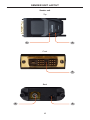
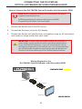
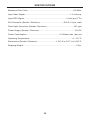
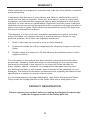
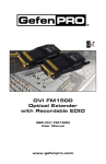
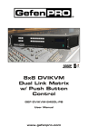
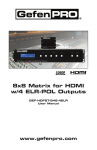
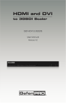
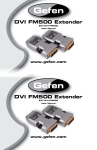
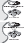
DVI FM1500
Optical Extender
with Recordable EDID
GEF-DVI-FM1500
User Manual
www.gefenpro.com
ASKING FOR ASSISTANCE
Technical Support:
Telephone
(818) 772-9100
(800) 545-6900
Fax(818) 772-9120
Technical Support Hours:
8:00 AM to 5:00 PM Monday through Friday, Pacific Time
For 24 / 7 support, see the back of the product for the support number
Write To:
Gefen LLC
c/o Customer Service
20600 Nordhoff St
Chatsworth, CA 91311
www.gefenpro.com
[email protected]
Notice
Gefen LLC reserves the right to make changes in the hardware, packaging, and
any accompanying documentation without prior written notice.
DVI FM1500 Optical Extender with Recordable EDID
is a trademark of Gefen LLC
© 2013 Gefen, LLC. All rights reserved.
All trademarks are the property of their respective owners.
Rev A8
CONTENTS
1Introduction
2
Operation Notes
3Features
4
Sender unit Layout
5
Sender unit Descriptions
6
Receiver unit Layout
7
Receiver unit Descriptions
8
Connecting the DVI FM1500 Optical Extender with Recordable EDID
8
9
Wiring Diagram
EDID Programming
10 Specifications
11Warranty
INTRODUCTION
Congratulations on your purchase of the DVI FM1500 Optical Extender with
Recordable EDID. Your complete satisfaction is very important to us.
GefenPRO
In the realm of video distribution, certain features are invaluable in a commercial
or broadcast environment. Accommodations such as a build-in power supply
and flat black rack-mount enclosures set GefenPRO apart from our traditional
products. Complex distribution units allow for professional DVI, 3G-SDI, and
HDMI signals to be routed and converted easily and seamlessly, while being
backed up by a renowned and dependable technical support team. Gefen invites
you to explore the GefenPRO product line and hopes that you find the solution
that fits your needs.
The GefenPRO DVI FM1500 Optical Extender with Recordable EDID
The GefenPRO DVI FM1500 Optical DVI Extender with Recordable EDID
extends a DVI source up to 3280 feet (1000 meters) using single-mode fiber optic
cable. Recordable EDID programming provides fast integration and compatibility
with the input video source and the display. Resolutions up to 1920 x 1200
(WUXGA) at 60 Hz are supported.
How It Works
Connect the Sender unit to the DVI source. Connect the Receiver unit to the DVI
display. Use a single strand of SC-terminated fiber optic cable to connect the
Sender unit to the Receiver unit. Connect the included 5V DC power supply to
the Receiver unit and connect the power adapter to an available electrical outlet.
If the source does not supply enough power to the Sender module, connect the
other included power supply.
1
OPERATION NOTES
READ THESE NOTES BEFORE INSTALLING OR OPERATING
THE DVI FM1500 OPTICAL EXTENDER WITH RECORDABLE EDID
•
The DVI FM1500 Optical Extender with Recordable EDID can use both
single-mode and multi-mode SC-terminated optical fiber cables.
•
This product does not support interlaced video resolutions such as 1080i.
•
The DVI FM1500 Sender unit has a default built-in EDID of 1920 x 1200.
If the Sender unit is programmed with another EDID (see page 9), the
default EDID will be erased. Once the default EDID is erased, it cannot be
restored.
2
FEATURES
Features
•
Extends DVI up to 3280 feet (1000 meters) using single-mode fiber optic
cable
•
Extends DVI up to 1640 feet (500 meters) using multi-mode fiber optic cable
•
Supports resolutions up to 1920 x 1200 (WUXGA)
•
Optical signal transmission provides good immunity to electromagnetic
interference
•
Virtual EDID programming feature provides quick installation and
compatibility between source and display
•
Uses single-mode or multi-mode fiber optic cable
•
Fully supports DVI 1.0 Specifications and DDC2B via virtual DDC
•
Sender module does not require power if the DVI source provides sufficient
power on pin 14 of the DVI connector (most sources do)
Package Includes
(1) GefenPro DVI FM1500 - Sender unit
(1) GefenPro DVI FM1500 - Receiver unit
(2) 5V DC power supplies
(1) Quick Start Guide
3
SENDER UNIT LAYOUT
Sender unit
Top
1
2
Front
3
Back
4
5
4
SENDER UNIT DESCRIPTIONS
1
Status
This LED indicator will slowly blink bright green, indicating that there is a valid
connection between the Sender unit and Receiver unit.
2
Power
This LED indicator will glow bright green, when power is applied to the Sender
unit.
3
DVI Input
Connect this part of the Sender unit to the DVI source.
4
SC Fiber Connector
Connect an SC-terminated fiber cable from this SC connector to the
SC-connector on the Receiver unit.
5
5V DC Power Supply Connector
If the source does not supply enough voltage to power the Sender unit, connect
one of the included 5V DC power supplies. In most situations, the power supply
will not be required.
5
RECEIVER UNIT LAYOUT
Receiver unit
Top
1
2
Front
3
Back
4
5
6
RECEIVER UNIT DESCRIPTIONS
1
Status
This LED indicator will slowly blink bright green, indicating that there is a valid
connection between the Sender unit and Receiver unit.
2
Power
This LED indicator will glow bright green, when power is applied to the Receiver
unit.
3
DVI Output
Connect this part of the Receiver unit to the DVI display.
4
SC Fiber Connector
Connect an SC-terminated fiber cable from this SC connector to the
SC-connector on the Sender unit.
5
5V DC Power Supply Connector
Connect one of the included 5V DC power supplies.
7
CONNECTING THE DVI FM1500
OPTICAL EXTENDER WITH RECORDABLE EDID
How to Connect the DVI FM1500 Optical Extender with Recordable EDID
STOP: Before continuing, connect one of included 5V DC power
supplies to the Receiver unit.
If EDID programming is required, then skip to the EDID
Programming Procedure on the next page.
1. Connect the Sender unit to the DVI source.
2. Connect the Receiver unit to the DVI display.
3. Connect the Sender unit and Receiver unit together using an SC-terminated
multi-mode (or single-mode) fiber optic cable.
IMPORTANT: In most cases the Sender module will not require a
power supply as long as the DVI source provides sufficient power
on pin 14 of the DVI connector. If you are unsure that the source
will supply enough power to the Sender unit, it is recommended that
the included power supplies be connected to both the Sender and
Receiver unit when powering the DVI FM1500 Optical Extender.
Wiring Diagram for the
DVI FM1500 Optical Extender with Recordable EDID
FIBER OPTIC CABLE
®
Sender
DVI Source
Receiver
DVI Display
GEF-DVI-FM1500
8
EDID PROGRAMMING
Virtual EDID Programming Procedure
If an EDID is not required by the DVI source, then EDID programming will not be
necessary. EDID programming is required if the maximum resolution of the
display does not support 1920 x 1200 (WUXGA).
IMPORTANT: The DVI FM1500 Sender unit has a default built-in
EDID of 1920 x 1200. If the Sender unit is programmed with another
EDID (see page 9), the default EDID will be erased. Once the
default EDID is erased, it cannot be restored.
1. Power on the DVI display.
2. Connect the 5V DC power supply to the power receptacle of the Sender unit.
Make sure that the Power LED is ON and that the Status LED is blinking
slowly.
3. Press and hold the EDID PRGM button on the Sender unit using a small
pointed object. The Status LED will turn OFF.
Sender unit
Press and hold the EDID
PRGM button.
4. Connect the Sender unit to the display (not to the source).
5. The Status LED on the top of the Sender unit will begin to blink rapidly,
indicating that the EDID is being read from the display and stored in the
Sender unit. After about 10 seconds, the Status LED will blink slowly to
indicate that the EDID programming procedure was successful.
6. Disconnect the Sender unit from the display.
7. Disconnect the power supply from the Sender unit.
8. Connect the 5V DC power supply to the Receiver unit and connect the
Receiver unit to the display.
9. Connect the Sender unit to the DVI source.
9
SPECIFICATIONS
Maximum Pixel Clock................................................................................165 MHz
Input Video Signal................................................................................1.2 volts p-p
Input DDC Signal...........................................................................5 volts p-p (TTL)
DVI Connector (Sender / Receiver)..........................................DVI-D, 19-pin, male
Fiber Optic Connector (Sender / Receiver).................................................SC type
Power Supply (Sender / Receiver)................................................................5V DC
Power Consumption..........................................................2.5 Watts (max.) per unit
Operating Temperature.............................................................................0 ~ 50 °C
Dimensions (Sender / Receiver)..................................1.54” W x 0.57” H x 2.68” D
Shipping Weight..............................................................................................2 lbs.
10
WARRANTY
Gefen warrants the equipment it manufactures to be free from defects in material
and workmanship.
If equipment fails because of such defects and Gefen is notified within two (2)
years from the date of shipment, Gefen will, at its option, repair or replace the
equipment, provided that the equipment has not been subjected to mechanical,
electrical, or other abuse or modifications. Equipment that fails under conditions
other than those covered will be repaired at the current price of parts and labor in
effect at the time of repair. Such repairs are warranted for ninety (90) days from
the day of reshipment to the Buyer.
This warranty is in lieu of all other warranties expressed or implied, including
without limitation, any implied warranty or merchantability or fitness for any
particular purpose, all of which are expressly disclaimed.
1. Proof of sale may be required in order to claim warranty.
2. Customers outside the US are responsible for shipping charges to and from
Gefen.
3. Copper cables are limited to a 30 day warranty and cables must be in their
original condition.
The information in this manual has been carefully checked and is believed to
be accurate. However, Gefen assumes no responsibility for any inaccuracies
that may be contained in this manual. In no event will Gefen be liable for
direct, indirect, special, incidental, or consequential damages resulting from
any defect or omission in this manual, even if advised of the possibility of such
damages. The technical information contained herein regarding the features and
specifications is subject to change without notice.
For the latest warranty coverage information, refer to the Warranty and Return
Policy under the Support section of the Gefen Web site at www.gefen.com.
PRODUCT REGISTRATION
Please register your product online by visiting the Register Product page
under the Support section of the Gefen Web site.
11
Rev A8
20600 Nordhoff St., Chatsworth CA 91311
1-800-545-6900
818-772-9100
www.gefenpro.com
Pb
This product uses UL listed power supplies.
fax: 818-772-9120
[email protected]