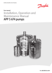
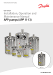
Download Installation & operation Manual iSave 21
Transcript
MAKING MODERN LIVING POSSIBLE User Guide Tel: +44 (0) 1706 869777 E‐mail: [email protected] Web: www.desal.co.uk Installation, Operation and Maintenance Manual iSave 21 isave.danfoss.com User manual iSave 21 Document information and copyright Installation, Operation and Maintenance Manual. Original operating manual document. Danfoss can accept no responsibility for possible errors in the manual and instructions. Danfoss reserves the right to alter its products without notice. This also applies to products already on order provided that such alterations can be made without subsequential changes being necessary in specifications already agreed. All rights reserved. Contents provided herein must neither be distributed, copied, reproduced, edited or processed for any other purpose, nor otherwise translated or published without Danfoss’ express written consent. Validity This manual is valid for iSaves with: 1. Code no 180F7000 Serial no 2. From week 145 year 2011 2. Code no 180F7001 Serial no 2. From week 14 year 2011 2 180R9221 / 521B1174 / DKCFN.PS.003.A2.02 / 06.2012 User manual iSave 21 Table of Contents 1 CE Declaration of conformity 5 2 Introduction 2.1General 2.2 Target group 2.3Symbols 2.4 Manufacturer and customer service adress 2.5 Additional technical documents 6 6 6 6 7 7 3Safety 3.1General 3.2 Intended use 3.3 Application range 3.4 Preferred system design 8 8 9 9 10 4 Arrival inspection, handling and storage10 4.1 Arrival inspection 10 4.2 Return to the supplier 10 4.3Handling 10 4.3.1 Centre of mass 11 4.4Storage 12 4.5 Outdoor storage 12 5 Technical data and design review13 5.1 Design details 13 5.2 Sound level of the iSave 13 5.3Materials 14 5.4 Temperature and corrosion 14 5.5 Dimensions and weights 14 5.6 Electrical motor data 14 5.7 How does the iSave work? 15 5.7.1 Pressure excharger function 15 5.7.2 Booster pump 16 5.7.3 Lubrication flow 16 5.7.4 Mixing 16 5.7.5 How does the iSave work in an RO system? 16 5.8 Seawater quality 17 5.8.1 Pre-filtration 17 5.8.2 Air bubbles 18 5.8.3 Chemicals 18 5.9 Initial start up and flushing 18 5.10 Initial start up and settings of safety equipment 18 5.11Flushing 19 5.12 CIP of Membrane cleaning 19 5.13 High pressure remains after shutdown 19 5.14 Over-pressurisation caused by low pressure isolation 20 5.15 Over-pressurisation caused by the high pressure pump 20 5.16 Preferred system design and P&ID 21 180R9221 / 521B1174 / DKCFN.PS.003.A2.02 / 06.2012 3 User manual iSave 21 6 On-site installation 22 6.1 General 22 6.2 Installation and alignment 22 6.3 Orientation 22 6.4 Piping and joints 23 6.5 Flexible couplings and flexible hoses 24 6.6 Mounting of coupling 24 6.7 Mounting of bell housing on iSave 24 6.8 Accessibility 25 6.9 Drives 25 6.9.1 Electric motor 25 6.9.2 Speed control 25 6.9.3 Starting torque on the iSave/ramping the electric motor 25 6.9.4 Torque overloads protection on the iSave 25 7 Commissioning, start-up and shutdown 7.1 Safety regulations 7.2 Support 7.3 Commisioning 26 26 26 26 8 Service/Maintenance 8.1 Safety regulations 8.2 Support 8.3 Maintenance schedule 8.4 Tool used 27 27 27 27 28 9Trouble-shooting29 9.1 Safety regulations 29 10 Appendix 10.1 Start and stop procedures (180R9213) 10.2 Membrane cleaning of the RO system with iSave unit (180R9214) 10.3 Datasheet (521B1116) 10.4 iSave part list (180R9209) 10.5 iSave overload protection (180R9222) 10.6 Hose assembly and installation (180R9084) 10.7 Service instructions - assembly and disassembly (180R9219) 10.8 Operating- and maintenance instruction, electric motor (180R9163) 4 180R9221 / 521B1174 / DKCFN.PS.003.A2.02 / 06.2012 30 31 37 43 59 71 81 85 103 1. CE Declaration of Conformity 180R9221 / 521B1174 / DKCFN.PS.003.A2.02 / 06.2012 5 User manual iSave 21 2. Introduction 2.1 General iSave is manufactured by Danfoss A/S, and is sold and marketed by a net of authorised distributors world wide. This manual contains the necessary instructions for the installation, operation and service of the iSave. All personnel who are responsible for the operation and maintenance of the iSave unit must read and fully understand these instructions, especially the section “Safety” before: • Transporting of the iSave unit. • Lifting the unit. • Installing the iSave unit on a frame. • Connecting the iSave unit to the fluid system. • Connecting the electrical motor and instrumentation. • Commissioning the unit. • Servicing the iSave unit, mechanics and electrics. • Decommissioning the iSave unit. Ensure that these instructions are always readily available to all personnel concerned. 2.2 Target group This manual is intended for use by personnel with qualified training and experience in the operation and maintenance of a Sea Water Reverse Osmosis (SWRO) or Brackish Water Reverse Osmosis (BWRO) system. 2.3 Symbols NB! Indicates something to be noted by the reader Indicates a situation which will or could result in damage to the iSave and its function Indicates a situation which will or could result in personal injury and/or damage to the iSave Electrical hazard. Indicates a high-voltage warning Safety glasses required Hearing protection required Safety shoes required Safety helmet required 6 180R9221 / 521B1174 / DKCFN.PS.003.A2.02 / 06.2012 User manual iSave 21 2.4 Manufacturer and customer service adress Danfoss A/S DK-6430 Nordborg, Denmark Telephone: +45 7488 2222 Email: [email protected] Home page: www.ro-solutions.com 2.5 Additional technical documents Document name Content Datasheet Description of the technical data and dimensions of the iSave iSave partlist Sectional drawings, parts list and spare part numbers. Instruction: start and stop of the SWRO with iSave unit Description of how to start and stop the iSave in the preferred RO system set-up. Instruction: Membrane cleaning of RO system with iSave unit Description of how to clean the membranes in the preferred RO system set-up. Instruction: iSave overload protection Electrical wiring diagram on how to protect the iSave against overload. Mechanical overload protection of the iSave Instruction: Hose assembly and installation Guideline for Hose assembly and installation Service instructions Assembly and disassembly Description of how to assembly and disassembly the iSave Operating and maintenance instructions, electric motor Operating and maintenance instructions for the standard electric motor, delivered from Danfoss. See also appendix 10 180R9221 / 521B1174 / DKCFN.PS.003.A2.02 / 06.2012 7 User manual iSave 21 3. Safety 3.1 General The iSave must not be used for other purposes than those recommended and specified without first consulting your local iSave distributor. This manual must be read and completely understood by the responsible specialist personnel prior to installation and commissioning. Use of this manual does not relieve operation and maintenance personnel of the responsibility of applying normal good judgment in the operation and care of this product and its components. This manual must be available to all personnel concerned at the site at all time. An iSave must always be installed and used in accordance with existing national and local sanitary and safety regulations and laws. It is the responsibility of the safety officer or the chief operator to assure compliance with all local regulations that are not taken into account in this manual. The iSave is a rotating machine that typically operates at high pressure. Always wear suitable safety and lifting equipment when handling the iSave. • Bolt the iSave properly to the base before start-up to avoid personal injury and/or damage to the iSave. • The pipe connections to the iSave must be stress-free mounted, securely fastened to the iSave and well supported. Improper installation will or could result in personal injury and/or damage to the iSave. • Proper installation and care of shutdown devices and over-pressure protection equipment is essential. Electrical hazard • All electrical installation work must be carried out by authorised personnel in accordance with EN60204-1 and/or local regulations. • Install a lockable circuit breaker to avoid inadvertent starting. Protect the motor and other electrical equipment from overloads with suitable equipment. • The electric motors must be supplied with adequate cooling ventilation. • Improper installation can cause fatal injuries. • The iSave must not operate outside the application range. • During the initial start-up, slowly raise the pressure of the system and adjust the overpressure protection equipment for proper limit settings. • Make sure that the pressure is released from the iSave before the iSave is disconnected from any pipe or hose connections in the iSave. • Make sure that the iSave can be drained without injuring anyone and without contaminating nearby equipment or the environment. • Before intervening in the iSave/system, the power must be shut off and the starting device must be locked. When intervening in the iSave unit, follow the instructions for Service/Maintenance, chapter 8. • A failure to follow the instructions can result in personal injury and/or damage to the iSave. It will also invalidate the warranty. NB! 8 • The iSave must never run dry. Dry running produces heat and will cause damage to internal parts. • If the iSave does not function satisfactorily, contact your local iSave distributor. Use of this manual does not relieve operation and maintenance personnel of the responsibility of applying normal good judgment in the operation and care of this product. 180R9221 / 521B1174 / DKCFN.PS.003.A2.02 / 06.2012 User manual iSave 21 3.2 Intended use The iSave is designed for use as energy recovery device in Sea Water Reverse Osmosis (SWRO) or Brackish Water Reverse Osmosis (BWRO) system. The iSave must not be used for other purposes than recommended and quoted for without consulting your local iSave distributor. 3.3 Application range The iSave should only be used within the following limits: High-pressure inlet flow, maximum 21 m3/hr (92.4 gpm) Low-pressure inlet flow, maximum 33 m3/hr (145 gpm) High-pressure inlet pressure, maximum 83 Bar (1200 psig) High-pressure inlet pressure, minimum 10 Bar (145 psig) High-pressure inlet pressure, intermittent, minimum 3 Bar (43.5 psig) Low-pressure inlet pressure, maximum 10 Bar (145 psig) Low-pressure outlet pressure, minimum 1 Bar (14.5 psig) High-pressure outlet pressure, maximum 83 Bar (1200 psig) Torque, maximum 36 Nm (26.5 lbf-ft) Maximum speed 1500 rpm Minimum speed 500 rpm Filtration requirements (See section 5.8.1) 3 μm melt-blown Maximum water temperature 50 C (122 F) Asynchronous motor according to DIN-IEC and VDE 0530 standards. Voltage and frequency according to IEC 38. The motors are fitted with a rating plate in multi-tension: 380-420 V / 660-720 V, 50 Hz or 440-480 V, 60 Hz Tolerance ± 5% according to VDE 0530 Insulation according to DIN-IEC 34 Class F Ambient temperature 40°C, 1000m above sea level Class B Degrees of protection, minimum IP55 Specific application limits are provided in the datasheet of the iSave. Application limits vary from model to model. Applications not suitable for the iSave can cause damages to the iSave unit, with risk of personal injury. 180R9221 / 521B1174 / DKCFN.PS.003.A2.02 / 06.2012 9 User manual iSave 21 3.4 Preferred system design Danfoss recommends building systems with a high degree of safety. The PI&D in chapter 5.16 shows the Danfoss preferred system design. • It is always the system builders’ responsibility that the system design does not cause any form of hazard and are adapted to local regulations. • Proper installation and care of shutdown devices and over-pressure protection equipment is essential. 4. Arrival inspection, handling and storage 4.1 Arrival inspection The iSave is packed in a wood container with plugs in the port connections to protect the unit from damage during transport. Remove all packing materials immediately after delivery. Immediately check the shipment for damage on arrival and make sure that the name plate/type designation is in accordance with the packing slip and your order. In case of damage and/or missing parts, a report should be drawn up and presented to the carrier at once. The identification label on the iSave states the specific type, the serial number and the code number of the iSave; see fig. below. The last three digits of the Serial No. indicate the week and year of production. 4.2 Return to the supplier Flush the iSave with clean water. Drain the iSave and plug the port connections with a cap/cover. Pack the iSave into a suitable container and make sure that it is suitably fastened to the container. Please contact your local authorised distributor or: Danfoss A/S DK-6430 Nordborg, Denmark Telephone: +45 7488 2222 Fax: +45 7445 3831 Email:[email protected] Homepage:www.ro-solutions.com 4.3 Handling • Personnel involved in lifting and transportation of the equipment must be trained in proper handling and safety procedures. • Observe the local regulations regarding lifting. • Use suitable, permitted lifting equipment. • The iSave (set) could slip the lifting arrangement. • Be aware of individuals located in the operation area while lifting the component. 10 180R9221 / 521B1174 / DKCFN.PS.003.A2.02 / 06.2012 User manual iSave 21 Check the mass (weight) of the iSave unit. All parts weighing more than 20 kg must be lifted using lifting slings and suitable lifting devices, e.g. an overhead crane or industrial truck. All iSave units weight more than 20 kg. Secure lifting slings around the part of the iSave and the back of the electric motor. Make sure that the load is balanced before attempting the lift. Never lift the iSave unit with only one fastening point. Incorrect lifting can result in personally injury and/or damage to the unit. Never lift the iSave in the bell housing. Incorrect lifting can result in personally injury and/or damage to the unit. 4.3.1 Centre of mass 180R9221 / 521B1174 / DKCFN.PS.003.A2.02 / 06.2012 11 User manual iSave 21 4.4 Storage Each iSave is tested before shipment and therefore holds water. Storage temperature: 1°C to +70°C (33°F to 158°F) – provided that the pump is drained of fluid and stored “plugged”. Frost protection is required at temperatures below 1°C. Danfoss recommends using DOWFROST from DOW Chemical Company or Chillsafe mono propylene glycol from Arco Chemical Company. If the iSave is protected against frost, the storage temperature can be: -40°C to +70°C (-40°F to 158°F) • The iSave is NOT delivered frost-protected from the factory. • Only remove caps from the openings of the iSave at the time of installation. 4.5 Outdoor Storage For outdoor storage cover the iSave (set) with waterproof material. 12 180R9221 / 521B1174 / DKCFN.PS.003.A2.02 / 06.2012 User manual iSave 21 5. T echnical data and design review 5.1 Design details 1: 2” Victaulic connections 2: Shaft 3: Low pressure shaft seal 4: Port flange 5: Port plate 6: Valve plate 7: Cylinder drum 8: Port flange 9: Port plate 10: Pins 11: Vanes 12: Port plate 13: Coupling 14: Adapter flange 15: Rotor 16: Stator 17: Port flange 18: Outlet flange 5.2 Sound level of the iSave The noise level from the iSave including the electrical motor is 86 dB (A). Measurements according to EN ISO 20361. The test is made under following conditions: 1. iSave and electrical motor mounted on Danfoss base plate. 2. Baseplate is isolated from concrete ground by rubber vibration dampers. 3. Flexible hoses are used on high pressure and low pressure sides of the iSave. 4. Rotation speed 1500 rpm 5. System pressure 60 bar and a booster pressure of 3 bar. Influences Since the iSave is mounted on a base plate and connected to the electromotor by a bell housing, the noise level can only be determined for the complete unit (system). It is therefore important that the iSave unit is mounted correctly on a frame with dampers to minimise vibrations and noise. It is also strongly recommended to use high-pressure flexible hoses between the hard piping in the RO plant and the iSave. See “hose assembly and installation” in appendix 10.6. Alternative use multiple flexible Victaulic® couplings on the hard piping. The noise level is influenced by: • The speed of the iSave. High speed creates more noise than low speed. • Rigid mounting of the iSave baseplate generates more noise than flexible mounting • Pipe mounting directly to the iSave increases the noise level compared to flexible hoses. 180R9221 / 521B1174 / DKCFN.PS.003.A2.02 / 06.2012 13 User manual iSave 21 5.3 Materials All critical parts of the iSave are made of super-duplex 1.4410/UN S32750 or the like. Non-critical parts that are not in contact with sea water are made of AISI316. The shaft to the electrical motor is sealed by a standardised mechanical seal. For a detailed material/part overview see appendix 5.4 Temperature and corrosion The chart below illustrates the corrosive resistance of different types of stainless steel related to NaCl concentration and temperature. Depending on the NaCl concentration, the fluid temperature must be between: +2°C to +50°C (+35.6°F to 122°F). In order to minimise the risk of crevice corrosion, always flush the iSave according to the specified start/stop procedure. 5.5 Dimensions and weights For dimensions and weights please refer to the iSave datasheet. See appendix 10.3. 5.6 Electrical motor data See datasheet in appendix 10.3 and “Operating and Maintenance instructions, electric motor” in appendix 10.8. 14 180R9221 / 521B1174 / DKCFN.PS.003.A2.02 / 06.2012 User manual iSave 21 5.7 How does the iSave work? Figure 5.1 shows a section view of the iSave The iSave consists of a rotating isobaric pressure exchanger and a positive displacement pump, also called booster pump. The rotation speed of the pressure exchanger and the pump is exactly the same, as they are driven by the same electric motor. Fig. 5.1. HP-in Concentrate side HP-out Seawater side LP-in LP-out 5.7.1 Pressure exchanger function: The pressure exchanger consists of two port plates, one at the concentrate side and one at the seawater side. In between there is a rotor with several ducts that connect the concentrate side with the seawater side. The pressure exchanger transfers pressure from the high-pressure (HP) concentrate (HP in) to the low-pressure (LP) seawater coming from low-pressure feed pump (LP in). To separate the HP side from the LP side there is a sealing zone on both port plates. A single duct in the rotor is either on the HP side, or on the LP side or in the sealing zone. A single duct is never in contact with more than one zone at the time. When the rotor rotates a duct will go from the LP zone over the first sealing zone into the HP zone, and hereafter from the HP zone over the second sealing zone and back to the LP zone. The flow through the HP side of the iSave is forced and controlled by the booster pump. When the high-pressure concentrate is flowing into the iSave it pressurizes the sea water in the duct coming from “LP in”. The pressurized seawater is then pumped out of “HP out”. Just before the HP concentrate in the duct comes to the seawater port plate, the duct goes into the sealing zone and the flow in the duct stops. When the duct goes into the LP zone the concentrate water is de-pressurized. The (LP) seawater coming from the LP feed pump (LP in) forces the LP concentrate out of “LP out”. This pressure exchange process is repeated for each duct with every rotation of the rotor, and the ducts are thus continuously filling and discharging. The flow on the HP side and LP side of the iSave is nearly constant over time. There is no physical barrier in the ducts between the concentrate and seawater. This means that there will be a small amount of mixing between the two liquids. NB! When the iSave is rotating the water always flows respectively from LP-in to HP-out, AND from HP-in to LP-out. However, if the feed flow into LP-in is higher than the flow into HP-in, some of the LP feed flow will flow directly to LP-out. When the iSave is not rotating the seawater can only run directly from LP-in to LP-out. 180R9221 / 521B1174 / DKCFN.PS.003.A2.02 / 06.2012 15 User manual iSave 21 5.7.2 Booster pump The booster pump is a positive displacement pump, which means that the flow is controlled by the speed of the electric motor; e.g. if the rotation speed of the electric motor is raised by 10%, the flow will be 10% higher and vice versa. The required rpm can be calculated based on the “rated flow” of the particular iSave. See datasheet in appendix 10.3. At low speeds you may hear some minor clicking sounds from the pump. This is normal and is caused by the pins in the vane pump. 5.7.3 Lubrication flow To lubricate the moving parts in the pressure exchanger there is a well defined leak between the port plates and the rotor, as well as in the high pressure bearing between the pressure exchanger and the booster pump. This leak is typically called “lubricating flow”. The leaks go from the high pressure side to the low pressure side of the pressure exchanger, and from the booster pump to the low pressure side of the pressure exchanger. 5.7.4 Mixing There is no physical barrier in the ducts between the concentrate and seawater. This means that there will be a small amount of mixing between the two liquids. Because the two liquids are in contact for a short amount of time, the mixing is relatively low. On the RO market the mixing rate is defined as “balanced flow” when HP-in is equal to LP-in. Experience from the market shows that the corresponding increase in membrane operating pressure is about 1 bar. The customer can reduce mixing by over-flushing the LP feed with excess feed water. See figure below. Over-flushing means energy loss. Optimal over-flushing is obtained when the energy loss on LP feed is equal to or less than the energy loss caused by the excess pressure at the membrane. 5.7.5 How does the iSave work in an RO system? The figure below illustrates a typical Flow Path of an SWRO or BWRO with an iSave. 16 180R9221 / 521B1174 / DKCFN.PS.003.A2.02 / 06.2012 User manual iSave 21 The high-pressure (HP) concentrate (7) flows to the low-pressure (LP) concentrate outlet (3). The LP sea water (2) flows to the HP sea water outlet (5). The rotor, moving between the high-pressure and low-pressure streams, removes the highpressure concentrate (7) and replaces it with feed water (2). The flow rate on the HP sea water outlet (5) is controlled by the iSave alone. The flow rate on the LP concentrate outlet (3) is controlled by the sea water feed pump (1) and the back pressure valve. This means that changing the LP feed flow (2) will not affect HP outlet flow (5) and, vice versa, that changing the HP outlet flow (5) will not affect the LP outlet flow (3). As LP sea water (2) is flushing the LP concentrate to LP outlet (3), it is essential that the flow on the LP inlet (2) is equal to or slightly higher than the HP inlet (7). Otherwise there will be an “under-flush” and higher mixing will occur in the HP outlet (5). This higher mixing will result in a slightly higher pressure at the membrane. The booster pump integrated in the iSave must only overcome the pressure drop from the high-pressure outlet (5) to the high-pressure inlet (7). During the RO process operation, water is pumped into the HP-membrane feed (6) by the HP pump (4) and the iSave (5). Almost all water coming from the HP pump (4) penetrates the membranes (8). Only a slight amount of the water is used as lubrication flow in the iSave. The lubrication flow is measured as the difference between the HP pump flow rate (4) and the permeate flow rate (8). The resistance to permeate in the membrane pressurises the HP loop. The isobaric pressure exchanger technology in an SWRO or BWRO change the HP concentrate into HP seawater that is feed into the HP membranes. The iSave energy recovery technology thus significantly reduces flow needed from the main HP pump (4). Overall energy consumption of a SWRO or BWRO plant using the iSave depends on the recovery rate. The operator can change the recovery rate to optimise the RO system performance. Changing the recovery rate in an RO system equipped with iSave is easy. Using the VFD, change the speed of the iSave and thereby the flow in the HP flow rate. Then change the LP feed (2) flow to the iSave to minimise mixing and optimise energy consumption. Make sure that flow and pressure are within the rated parameter of the iSave in question. 5.8 Seawater quality 5.8.1 Pre-filtration It is important that the incoming water is filtered properly to assure optimum service life of the iSave. A true graded density melt-blown depth filter cartridge rated at 3 μm is therefore recommended. Poor pre-filtration of the feed water will result in reduced service life of the iSave. The iSave may request a different pre-filter of the seawater than the HP pump and other components in the RO system. As the various filters on the market differ greatly, Danfoss RO Solutions recommends using cartridges with consistent, reliable performance and high efficiency, in which fibres are blown continuously onto a central support core. Danfoss RO Solutions does not recommend cartridges requiring any type of binders or resins. NB! NB! Filters can be purchased from Danfoss RO Solutions. 180R9221 / 521B1174 / DKCFN.PS.003.A2.02 / 06.2012 17 User manual iSave 21 For more information on the importance of proper filtration, please consult our publication “Filtration”, which also will provide you with an explanation of filtration definitions and guidance on how to select the right filter. See section 5.8.1 for filter installation instructions. 5.8.2 Air bubbles Large bubbles in a pressurised RO system can result in damage to piping and equipment. All air must be bleed from both the LP and HP before the RO system is pressurised. Special consideration should also be given to air bubbles in feed flow, continuously fed into the HP pump and iSave. 5.8.3 Chemicals The iSave should not be exposed to chemicals that will damage the RO membranes. 5.9 Initial start up and flushing Prior to the initial start-up, all piping associated with the iSave unit should be thoroughly flushed to assure that no impurities enter the iSave. Inadequate pre-flushing will strongly affect the life of the iSave and may lead to its eventual breakdown. It is recommended to disconnect all connections to the iSave and to thoroughly flush the piping before the iSave is connected to the inlet and outlet connections. It is essential that the water used for the final pre-flush is pre-filtered to a level described in chapter 5.8 It is recommended to install temporary basket strainers at both inlets to the iSave during the initial start-up and commissioning. Also see “Instruction for start and stop of the SWRO with iSave unit” in appendix 10.1. 5.10 Initial start-up and settings of safety equipment The high-pressure pump feed water into the high pressure line may be able to generate a pressure higher than the maximum allowable pressure in the system. There is thus a risk of personal injury and/or damage to the iSave. Depending of the type and size of the feed pump of the RO system, this pump may be able to generate a pressure higher than the maximum allowable pressure in the LP system. There is thus a risk that the iSave or the LP equipment could be damaged by over-pressurisation. To prevent such over-pressurisation, appropriate relief valves should be used and procedures should be implemented to safeguard the HP and LP sides of the iSave and/or the RO system. 18 180R9221 / 521B1174 / DKCFN.PS.003.A2.02 / 06.2012 User manual iSave 21 5.11 Flushing RO membranes require periodic flushing to limit biological fouling. There are two types of flushing: feed water (Seawater) flush and fresh water (Permeate) flush. Regardless of the flush water used, the water must be pre-filtered to the level described in chapter 5.8. All parts of the iSave must be flushed, i.e. LP- and HP flow channels. Feed water flushing is part of a normal shutdown sequence. After the HP pump has been stopped, the permeate and concentrate production will continue until the high-pressure drops below the osmotic pressure. Both the iSave and the LP seawater feed pump must run until the conductivity measured at point (7) and (3) are satisfactory. See also P&ID in chapter 5.16. Fresh water flushing is performed before every extended shutdown of the RO plant. Permeate is simultaneously fed into the iSave at LP in (2), and either to the HP pump inlet (1) or through some other injection point such as the CIP connections or full flow cleaning connection. See also P&ID in chapter 5.16. Permeate may be produced during this flushing process. NB! Special attention should be given to the pressure in the HP line (7) as the iSave may start to cavitate when it runs at high speed and the pressure in the HP line (7) drops below 3 bars. This can be avoided by reducing the speed of the iSave to about 750 rpm and keeping the pressure in the HP line at the minimum of 1 bar. At this low pressure the iSave may only run for a maximum of 10 minutes. Failing to flush the iSave with fresh water before extended shutdowns may result in extensive biological growth and cause corrosion in the iSave and other equipment in the RO system. 5.12 CIP or membrane cleaning The purpose of membrane cleaning is to reduce scaling and fouling in the membranes. For optimal performance specific chemicals are required, depending on the cause of the pollution. After chemical treatment the system must be flushed with fresh water. The flush water coming out of the membranes may consist of a large amount of suspended inorganic particles. It is important to assure that these particles are not lead into the iSave. It is essential that the water used for the final pre-flush is pre-filtered to a level described in chapter 5.8. The iSave should not be exposed to chemicals that will damage the RO membranes Also see instruction “Membrane cleaning of RO system with iSave unit” in appendix 10.2. 5.13 High pressure remains after shutdown The HP line of the RO system equipped with an iSave can remain pressurised for a long time after shutdown. Pressure decreases as water slowly leaks through the iSave. If more rapid system depressurisation is required, the system should be bled through a suitable valve on the HP concentrate line. Always check the pressure in the high-pressure lines before making service in the HP lines or pressurised equipment. 180R9221 / 521B1174 / DKCFN.PS.003.A2.02 / 06.2012 19 User manual iSave 21 5.14 Over-pressurisation caused by low pressure isolation If the low-pressure side of the iSave is blocked and the iSave is exposed to high-pressure, there is a risk that the iSave or the LP piping could be damaged by over-pressurisation. To prevent such over-pressurisation, appropriate relief valves should be used and procedures should be implemented to assure that the HP of the iSave is depressurised prior to the isolation of the LP side. 5.15 Over-pressurisation caused by the high pressure pump. The HP pump may be able to generate a pressure higher than the maximum allowable pressure for the iSave or the system – particularly if the HP pump is a positive displacement pump, the pump will be able to generate extremely high levels of pressure. To prevent such over-pressurisation, appropriate relief valves should be used and procedures should be implemented to assure that the HP of the iSave is protected against excess pressure. 20 180R9221 / 521B1174 / DKCFN.PS.003.A2.02 / 06.2012 iSave 21 5.16 Preferred system design and P&ID Media filter 4 6 5 17 F 2 F HP pump main filter M 1 Filter 3m nom. Flowmeter Permeate Flowmeter 18 3 Full flow cleaning F User manual 8 7 Flowmeter 12 HP out 19 LP in 11 10 Fresh water / perteate flush iSave 9 HP in Brine/concetrate VFD LP out M 14 13 16 15 Full flow cleaning Drain Explanation of P&ID setup • The pressure switch (3) must stop the iSave (11) and the high-pressure pump (4) at pressures lower than the minimum inlet pressure or higher than the allowable maximum pressure. • The non-return valve (18) prevents the high pressure flow from the membrane to flow back through the HP pump and into the low pressure piping. This may occur when the high pressure pump stops. • The pressure relief valve (6) protects the entire system against pressure overload and relieves the water if the pressure exceeds the maximum set pressure. If the high pressure pump is a positive displacement pump, the pump can build up a very high pressure that will exceed the mechanical strength of the membrane housing, pipes and other accessories. • The valve (8) bleeds the air out of the system. The valve must be placed at the highest point in the system. • The pressure relief valve (19) protects the low pressure pipes against pressure overload and relieves the water if the pressure exceeds the maximum allowable pressure. • Inlet filters assure proper water quality. High quality water extends the service life of the whole system. • The pressure switch (13) must stop the iSave when the pressure is lower than the minimum inlet pressure or higher than the maximum pressure. See “Start and stop” procedure, “Membrane cleaning” procedure and “iSave overload protection” instruction in appendices 10.1, 10.2. and 10.5. 180R9221 / 521B1174 / DKCFN.PS.003.A2.02 / 06.2012 21 User manual iSave 21 6. On-site installation 6.1 General For safety instructions see chapter 3.1 6.2 Installation and alignment The figure below illustrates the major iSave components. Fig. 1 1: Motor 6: Bolts 2: Flexible coupling 7: Support bracket (AISI 316) 3: Bell housing 8: Port connection 4: iSave 9: Bolts 5: Baseplate (AISI 316) The iSave is connected to the electric motor by the bell housing and a coupling. The bell housing is not suitable for bearing the weight of either the iSave or the motor. Both the iSave and motor must be supported without applying stress/load to the bell housing. Danfoss provides the iSave with a baseplate and support brackets. Although the baseplate is of a sturdy design, it can flex or bend when it is bolted to the foundation. The baseplate thus requires a solid foundation such as concrete or rigid steel frame. The baseplate itself must be aligned to avoid bending caused by bolting to an uneven foundation. A rigid foundation for the iSave assembly is important, and the iSave assembly must be bolted to the foundation. The bolts used must be of proper design and must be installed in accordance with the bolt manufacturer’s recommendations. To reduce noise it is recommended to use resilient mounts between the baseplate and the foundation. Make sure that the bolts are properly locked and will stay locked over time. An unlocked bolt can result in personal injury and/or damage to the iSave. Misalignment of the baseplate may cause stress and/or damage to the bell housing. 6.3 Orientation The iSave can be mounted horizontally and vertically. When mounted vertically, the electric motor must be placed above the iSave. 22 180R9221 / 521B1174 / DKCFN.PS.003.A2.02 / 06.2012 User manual iSave 21 6.4 Piping and joints Piping material and schedule is of high importance. The strength of the Victaulic® connections is influenced by the material used for both the Victaulic® clamps and the hard piping. The hard piping and connections used must be of proper design and must be installed in accordance with the manufacturer’s recommendations. Hard piping to the iSave must be properly aligned to avoid stress on the iSave port connections. Pipe connections must be aligned as shown in the figures below. Don’t use the iSave as a strain for hard piping. Correct piping alignment Incorrect piping alignment ! Incorrect piping alignment The hard piping and connections used must be of proper design and must be installed in accordance with the manufacturer’s recommendations. A failure to comply with this will or may result in personal injury and/or damage to the iSave. Misalignment of the hard pipes may place stress on the iSave port connection and may damage the iSave. 180R9221 / 521B1174 / DKCFN.PS.003.A2.02 / 06.2012 23 User manual iSave 21 6.5 Flexible couplings and flexible hoses The strength of the Victaulic® connections is influenced by the material used for both the Victaulic® clamps and hose couplings. The flexible hose and connections used must be of proper design and must be installed in accordance with the manufacturer’s recommendations. See also “Hose assembly and installation” in appendix 10.6 The flexible hose and connections used must be of proper design and must be installed in accordance with the manufacturer’s recommendations. A failure to comply with this will or may result in personal injury and/or damage to the iSave. 6.6 Mounting of coupling The figure below illustrates how to mount the flexible coupling between the iSave and to connect it to the electric motor. A: Flexible coupling B: Bell housing C: Motor shaft Any axial and radial load on the shaft must be avoided. 6.7 Mounting of bell housing on iSave The figure below illustrates how to mount the bell housing on the iSave. Screw the 4 bolts through the bell housing and into the iSave and tighten them to 30 Nm. 24 180R9221 / 521B1174 / DKCFN.PS.003.A2.02 / 06.2012 User manual iSave 21 6.8 Accessibility With respect to the service and replacement of the complete iSave unit, it is recommended to maintain sufficient space around the unit. The space must be sufficient enough to allow for safe lifting of the equipment, with no risk for personal injury and/or damage to the iSave. 6.9 Drives 6.9.1 Electric motor The iSave must only be driven by an electric motor. Using anything other than an electric motor can lead to an irreparable fracture of the iSave’s internal parts. 6.9.2 Speed control The rotation speed on the electric motor can be controlled by a VFD. The direction of rotation can be seen on the identification label. Checking the direction of rotation can be made by: 1. Looking at the fan in the end of the electric motor. 2. Removing the plug in the bell housing and watch the rotation of coupling. 3. Before assembly the iSave on the electrical motor, check the rotation of the shaft on the electrical motor. Special attention has to be on NON PROTECTED – FREE ROTATING shaft on the electrical motor. Ignorance will or could result in personal injury. • Running the iSave in the wrong direction for more than a few minutes can cause unintended wear on the iSave. • If the electric motor is running at a lower speed, extra care must be taken to ensure that the electric motor is NOT overheated. External cooling may be necessary. 6.9.3 Starting torque on the iSave/ramping the electric motor Because of the inertia of the iSave internal parts and the fact that the iSave includes a positive displacement pump, the torque will exceed the maximum allowable torque for the iSave when the speed is not ramped up from zero to maximum. It is required to use a VFD or a soft starter. A minimum of 10 seconds is required when ramping up the speed from zero to maximum. Otherwise, the torque on the iSave will exceed the maximum limit and may lead to an irreparable fracture of the iSave’s internal parts. 6.9.4 Torque overloads protection on the iSave The electric motor and iSave must always be protected against overload. Both at start-up and at continues operation the maximum torque on the iSave must be monitored. 180R9221 / 521B1174 / DKCFN.PS.003.A2.02 / 06.2012 25 User manual iSave 21 The electric motor must be shut of if the maximum torque of the iSave exceeds the defined limit. The response time of the power shutoff to the iSave must be of maximum 1 second. If more electric motors are powered by the same soft starter or VFD, each electric motor must be equipped with “torque limit equipment” to protect the iSave against overload. Below are examples of equipment which can measure the load on the electric motor or limit the torque on the iSave. 1. VFD with integrated current monitoring relays. 2. External current monitoring relays. 3. Torque limiter coupling. See also examples of “iSave overload protection” equipment in appendix 10.5 The electric motor and iSave must always be protected against overload. Otherwise, the torque will exceed the maximum limit and may lead to an irreparable fracture of the iSave’s internal parts. 7. Commissioning, start-up and shutdown 7.1 Safety regulations The operator ensures that all inspection and installation work is performed by authorised, qualified specialist personnel who are thoroughly familiar with the manual. Before starting up the iSave and the high pressure pump, make sure that the following requirements are met: • The iSave has been properly connected to the electric power supply and is equipped with all protection devices in accordance with EN60204-1. • Check that all motor protections are properly set. • All safety equipment, auxiliary equipment and connections required are proper connected and operational. • Check all bolts in all connections and in the foundation of the iSave and the pumps. 7.2 Support Danfoss A/S offers commissioning and service at system manufacturer’s location. Rate quotes are offered upon request. 7.3 Commissioning Before starting up the iSave and the high pressure pump make sure that the following requirements are met: • All pipes are flushed, free from debris and full of water. • The iSave has been bled and is full of water. • At pressure lower than 10 bars, check the system for leakage. Slowly raise the pressure in the system and set all pressure switches to the correct limit and continually check all connections for leakage. • Set pressure relief valve on both low and high pressure at the maximum system pressure. • Check high pressure hoses for proper assembly and inspect for external leakage for all connections. • At low pressure, start the iSave and check direction of rotation. • Start the system according to the “Start and stop procedure” instructions in appendix. 10.1 26 180R9221 / 521B1174 / DKCFN.PS.003.A2.02 / 06.2012 User manual iSave 21 8. Service/Maintenance 8.1 Safety regulations The operator ensures that all maintenance, inspection and installation work is performed by authorised, qualified specialist personnel who are thoroughly familiar with the manual. Before intervening in the iSave/system; • The power must be shut off and the starting device be locked. • The pressure in the High Pressure lines must be drained to the Low Pressure side. • The Water in all connected pipes must be drained. Always use suitable safety and lifting equipment when handling the iSave, and follow the instructions in chapter 4.3 • When saftey equipment has been adjusted make sure that proper re-adjustment has been made before start-up. • When the system is re-started after service and maintenance follow the instructions in chapter 7 and in “Start and stop procedures” in appendix. 10.1 8.2 Support Danfoss A/S offers commissioning and service at the system manufacturer’s location. Rate quotes are offered upon request. 8.3 Maintenance schedule The schedule of preventive maintenance below will help ensure that the iSave provides years of trouble-free performance. One day after commissioning: 1. Re-check bolts in the foundation and the baseplate of the iSave and tighten the bolts to specified torque if necessary. 2. Visually inspect all pipe connections / couplings for external leakage. 3. Re-check bolts in all pipe connections / couplings and tighten the bolts to specified torque if necessary. 4. Replace filters if necessary 5. Clean the filter housing and reinstall filters. Make sure no debris enters the system. Three months after commissioning: 1. Re-check bolts in the foundation and the baseplate of the iSave and tighten the bolts to specified torque if necessary. 2. Re-check alignment of iSave baseplate and iSave. 3. Visually inspect all pipe connections / couplings for external leakage. 4. Re-check bolts in all pipe connections / couplings and tighten the bolts to specified torque if necessary. 5. Replace filters if necessary. 6. Clean the filter elements and install the new filters. Make sure no debris enters the system. 7. Audibly inspect the iSave assembly. If there is irregular sounds or vibrations inspect the internals parts of the iSave and replace if necessary. 180R9221 / 521B1174 / DKCFN.PS.003.A2.02 / 06.2012 27 User manual iSave 21 8,000 hours of operation after commissioning: 1. Re-check bolts in the foundation and the baseplate of the iSave and tighten the bolts to specified torque if necessary. 2. Re-check alignment of iSave baseplate and iSave. 3. Visually inspect all pipe connections / couplings for external leakage. 4. Re-check bolts in all pipe connections / couplings and tighten the bolts to specified torque if necessary. 5. Replace filters if necessary. 6. Clean the filter elements and install the new filter. Make sure no debris enters the system. 7. Audibly inspect the iSave assembly. If there is irregular sounds or vibrations inspect the internals parts of the iSave and replace if necessary. 8. Visually inspect pump coupling and replace if necessary. 9. A udibly inspect the iSave assembly. If there is irregular sounds or vibrations inspect the internals parts of the iSave and replace if necessary. 10. Check power consumption and flow out of the iSave. If there is irregular performances inspect the internals parts of the iSave and replace if necessary. 11. Inspect and replace, if necessary, the vanes in the vane pump. Dimensions of the vanes iSave type iSave21 Original height (H) 27 mm Change when H is less than 26 mm Original length (L) 79,84 mm Change when L is less than 79,64 mm Annually: 1. See above section: “8,000 hour of operation after commissioning”. 2. See “Operating- and maintenance instruction, electric motor” in appendix 10.8 Follow manufacturer’s recommendations for electrical motor service and maintenance. 8.4 Tools used Tools needed for disassembly the iSave: - 6 mm and 8 mm allen key - 2 screwdrivers - 2 M8 bolts - Plastic tube - Plastic tool for shaft seal assembly - Loctite 270 28 180R9221 / 521B1174 / DKCFN.PS.003.A2.02 / 06.2012 User manual iSave 21 9. Trouble-shooting 9.1 Safety regulations The operator ensures that all inspection and installation work is performed by authorised, qualified specialist personnel who are thoroughly familiar with the manual. Before intervening in the iSave/system; • The power must be shut off and the starting device be locked. • The pressure in the High Pressure lines must be drained to Low Pressure side. • The water in all connected pipes must be drained. The numbers in () correspond to the preferred system design and P&ID Problem Possible cause VFD can’t start the iSave VFD is not designed for conat initial start-up. stant torque. Action Choose a VFD that is designed for constant torque. Ramp-up settings in the VFD is Set Ramp-up parameters cornot correct. VFD is tilting. rect. Torque on iSave too high during operation Valve (9) is closed Open valve (9) Pressure in the HP line (5) is too high Start the iSave only when the pressure in the HP line is low. Pressure difference from HPClean or change membranes. out (5) to HP-in (10) is too high. Debris in the booster pump or iSave. Wear in the booster pump or iSave. Design of the basic plant doesn’t fit the performance of the iSave. Permeate production is too low (17). Valves (6), (7), (8) or (16) are leaking. Repair or change valve. Internal leakage in iSave Repair iSave HP pump flow (2) is to small Incorrect speed on the HP pump. Check the HP pump and repair if necessary. Pressure on the membranes (5) is too high. Fouling on the membranes Clean the membranes Mixing in the iSave is too high. Check flow on LP-in (12) and adjust flow. Flow out of the iSave is too low, causes a recovery rate that is too high. Check speed on iSave and change if necessary. Booster pump in the iSave is worn out. Perform service on the VP. Pressure on the membranes (5) is too low. Valves (6), (7), (8) or (16) are leaking. Repair or change valve (s). Internal leakage in iSave Repair iSave HP pump flow (2) is too small Incorrect speed on the HP pump. Check the HP pump and repair if necessary. 180R9221 / 521B1174 / DKCFN.PS.003.A2.02 / 06.2012 29 User manual iSave 21 10. Appendix 10.1 Instruction for start and stop of the SWRO with isave unit (180R9213) 10.2 Membrane cleaning of the RO system with iSave unit (180R9214) 10.3 Data sheet (521B1116) 10.4 iSave part list (180R9209) 10.5 iSave overload protection (180R9222) 10.6 Hose assembly and installation (180R9084) 10.7 Service instructions - assembly and disassembly (180R9219) 10.8 Operating- and maintenance instruction, electric motor (180R9163) 30 180R9221 / 521B1174 / DKCFN.PS.003.A2.02 / 06.2012 User manual iSave 21 10.1 Instruction for start and stop of the SWRO with isave unit 180R9221 / 521B1174 / DKCFN.PS.003.A2.02 / 06.2012 31 User manual 32 iSave 21 180R9221 / 521B1174 / DKCFN.PS.003.A2.02 / 06.2012 Instruction Start and stop of the SWRO with iSave unit www.isave.danfoss.com 180R9213 / 521B1164 / DKCFN.PI.003.F2.02 Instruction Start and stop of the SWRO with iSave unit Below procedures are general guidelines for the start-up and shut-down functions of SWRO-systems with the Danfoss iSave Energy Recovery Device. Procedure details may differ depending on the system design. The numbers marked in () refer to the diagram below. Prior to start-up Prior to initial start-up all piping connected with the iSave unit must be thoroughly flushed to ensure that no impurities enter the iSave. Inadequate pre-flushing will strongly influence the life of the iSave and might lead to breakdown of the iSave. 1. Install all filter cartridges in the system. 2. With the iSave disconnected from the piping, the system must be flushed in order to remove possible impurities from the system (pipes, hoses, membranes etc.). Flushing must run until the system can be ensured clean. 3. Connect the iSave to the pipework. The iSave is now ready for start-up. 34 2 180R9221 / 521B1174 / DKCFN.PS.003.A2.02 / 06.2012 180R9213 / 521B1164 / DKCFN.PI.003.F2.02 / 03.2011 Instruction Start and stop of the SWRO with iSave unit Starting up the system 1. Make sure that all valves are set in normal operating positions. 2. Start the seawater supply pump (1) 3. Make sure all pipework is flushed with water. Vent all air from the system through air valve (8) and iSave unit (11). iSave has ¼” plugs to vent both the HP and LP side. 4. Start the iSave unit when the pipwork is full of water and the system and iSave unit has been bled. NB! Always start the iSave unit before the high-pressure pump is started. The speed of the iSave unit must be ramped up over a period of minimum 10 seconds. If possible run the iSave at maximum 750 rpm. 5. With a pressure control valve (15), adjust the back pressure of the “LP-out” to a minimum of 1 bar/14.5 psig (14). 6. An “over flush” of the iSave can be done to bleed any remaining air from the system. Flush minimum 10% higher flow rate (12) at “LP in” compared to the flow rate on “HP out”. Flush over a period of minimum 5 minutes. 7. Adjust the speed of the iSave unit to desired flow. The speed is controlled by a VFD. 8. Start the high-pressure pump (4), and the system pressure (5) will rise until the permeate flow (17) almost equals the flow (2) from the high-pressure pump. Check the low-pressure flow rates (12), and if required, adjust flow to achieve balanced flow to the iSave unit. It might be a benefit to “over flush” the iSave with up to 10% to lower the mixing. 1. If the “LP-in” flow (12) is too low and the “LP-out” pressure (14) is higher than 1 bar/14.5 psig, increase flow and pressure on the pressure control valve (15). 2. If the “LP-in” flow (12) is too low and the “LP-out” pressure (14) is below 1 bar/ 14.5 psig, adjust the flow by raising the flow from the seawater supply pump (1). 3. If the “LP-in” flow (12) is too high, reduce flow by the pressure control valve (15) or the flow from the seawater supply pump (1). 9. Check that the pressure (14) of “LP-OUT” is at least 1 bar/14.5 psig. 1-3 days system shutdown 1. The system is running in normal operation and producing permeate flow. 2. Stop the high-pressure pump (4). 3. Keep the iSave unit (11) running until the wanted pressure (5) at the membranes is reached and the TDS in the high-pressure line is equal to the TDS in the low-pressure line. NB! If the pressure (10) at “HP in” drops below 3 bars/43.5 psig, the sound will change of the iSave. This is due to cavitation. “HP in” pressure between 1-3 bars/43.5 psig is acceptable for less than 10 minutes within a period of 6 hours. Also see datasheet for iSave. If possible run the iSave at maximum 750 rpm. 4. Stop the iSave unit (11). 5. Stop the seawater supply pump (1). 3 180R9221 / 521B1174 / DKCFN.PS.003.A2.02 / 06.2012 180R9213 / 521B1164 / DKCFN.PI.003.F2.02 / 03.2011 35 Instruction Start and stop of the SWRO with iSave unit 4-14 days system shutdown 1. Run the “1-3 days’ system shutdown” procedure. 2. Supply fresh water to the iSave unit (11) and the SWRO system. Make sure that the iSave unit and the SWRO system are filled at the same time to ensure optimal flushing. 3. Run the system for 10 minutes while the iSave unit is running, until all seawater is discharged. NB! If the pressure (10) in “HP in” drops below 3 bars/43.5 psig, the sound will change of the iSave. This is due to cavitation. “HP in” pressure between 1-3 bars/43.5 psig is acceptable for less than 10 minutes within a period of 6 hours. Also see datasheet for iSave. If possible run the iSave at maximum 750 rpm. 4. Stop the iSave unit (11). 5. After minimum one minute delay, stop fresh water supply. Long-term system shutdown For a long-term shutdown period, the SWRO system including the iSave units must be thoroughly flushed with fresh water to remove any salt. Run the “1-3 days’ system shutdown” procedure. Further, any biological growth should be prevented. Make a final flush of the iSave unit with the same solution used to preserve the SWRO membranes. Flush both the high-pressure and low-pressure sides of the iSave (11). The high-pressure flush is performed by circulating the solution through the iSave unit and the membranes by rotating the iSave unit. NB! If possible run the iSave at maximum 750 rpm. 36 180R9221 / 521B1174 / DKCFN.PS.003.A2.02 / 06.2012 180R9213 / 521B1164 / DKCFN.PI.003.F2.02 / 03.2011 4 User manual 10.2 iSave 21 Membrane cleaning of the RO system with iSave unit 180R9221 / 521B1174 / DKCFN.PS.003.A2.02 / 06.2012 37 User manual 38 iSave 21 180R9221 / 521B1174 / DKCFN.PS.003.A2.02 / 06.2012 Instruction Membrane cleaning of the RO-system with iSave unit www.isave.danfoss.com 180R9214 / 521B1165 / DKCFN.PI.003.G2.02 Instruction Membrane cleaning of the RO-system with iSave unit Below procedures are general guidelines for the membrane cleaning of SWRO-systems with the Danfoss iSave. Procedure details may differ depending on the system design. The numbers marked in () refer to the diagram’s below. The purpose of membrane cleaning is to reduce scaling and fouling in the membranes. For optimal performance specific chemicals are required, depending on the cause of the contamination. After chemical treatment the system must be flushed with fresh water. The flushing water, coming out of the membranes, may consist of a large amount of suspended inorganic particles. It is important to assure that these particles are not fed into the iSave. NB! It is recommended to disconnect the piping from the “HP in” of the iSave and flush the contaminated water from the membranes directly to drain. By disconnecting the pipes there will be no accumulation of contaminations in the HP-piping and HP-valves. See P&ID no 2. Membrane cleaning The procedures below are based on Dow’s Cleaning and Sanitization: Cleaning steps described in Dow’s Form No. 609-02090-1005. Other procedure may be used depending on the membranes used. Below procedure is according P&ID no 1. 1. Stop the high-pressure pump (4), and stop the iSave (11). 2. Stop the seawater supply pump (1). 3. Close valve (9) and open valve (16). 4. Pump mixed cleaning solutions to the vessel at conditions of low flow rate and low pressure to displace the process water. Use only enough pressure to compensate for the pressure drop from feed to concentrate. The pressure should be low enough that essentially no or little permeate is produced. A low pressure minimizes re-deposition of dirt on the membrane. Dump the brine/concentrate to prevent dilution of the cleaning solution. 5. Recycle: After the process water is displaced, cleaning solution will be present in the concentrate/ brine stream. Recycle the cleaning solution from the piping to the cleaning solution tank. 6. Turn of the pump and allow the elements to soak. 40 2 180R9221 / 521B1174 / DKCFN.PS.003.A2.02 / 06.2012 180R9214 / 521B1165 / DKCFN.PI.003.G2.02 / 03.2011 Instruction Membrane cleaning of the RO-system with iSave unit Starting up the system 7. Feed the cleaning solution at high flow into the “full flow cleaning” adapter (7). The high flow rate flushes out the foulants removed from the membrane surface by the cleaning. 8. Flush RO permeate or deionised water into the “full flow cleaning” adapter (7). Flush out the cleaning solution. It is essential that the water used for the final pre-flush is pre-filtered to a level described in the datasheet. 9. Open valve (9) and flush trough the iSave. The iSave may start to rotate backward – this is OK. 10.When flushing is finalised – assure that no foulants remain in the piping or valve (9). 11.Close the high pressure “full flow cleaning” valve (7) and close valve (16). P&ID no. 1 Below procedure is according P&ID no 2. 1. Stop the high-pressure pump (4), and stop the iSave (11). 2. Stop the seawater supply pump (1). 3. Disconnect pipe in joint (9) and connect the pipe to low pressure “Full flow cleaning” joint (16). 4. Plug pipe in joint (9). 5. Open valve (16) 6. Pump mixed cleaning solutions to the vessel at conditions of low flow rate and low pressure to displace the process water. Use only enough pressure to compensate for the pressure drop from feed to concentrate. The pressure should be low enough that essentially no or little permeate is produced. A low pressure minimizes re-deposition of dirt on the membrane. Dump the brine/ concentrate to prevent dilution of the cleaning solution. 7. Recycle: After the process water is displaced, cleaning solution will be present in the concentrate stream. Recycle the cleaning solution from the piping to the cleaning solution tank. 8. Turn of the pump and allow the elements to soak. 9. Feed the cleaning solution at high flow into the “full flow cleaning” adapter (7) on the feed side of the membrane. The high flow rate flushes out the foulants removed from the membrane surface by the cleaning. 3 180R9221 / 521B1174 / DKCFN.PS.003.A2.02 / 06.2012 180R9214 / 521B1165 / DKCFN.PI.003.G2.02 / 03.2011 41 Instruction Membrane cleaning of the RO-system with iSave unit 10.Flush RO permeate or deionised water into the “full flow cleaning” adapter (7) on the feed side of the membrane. Flush out the cleaning solution. It is essential that the water used for the final pre-flush is pre-filtered to a level described in the datasheet. 11.Remove plug (9). Water will flow out of the iSave and the iSave may start to rotate backward – this is OK. 12.Continue to flush the iSave until no chemicals are coming out of the iSave. 13.When flushing is finalised – Close the high pressure “full flow cleaning” valve (7) and close valve (16). 14.Connect the high pressure pipe to joint (9) again. P&ID no. 2 Normal operation mode Membrane cleaning mode 42 180R9221 / 521B1174 / DKCFN.PS.003.A2.02 / 06.2012 180R9214 / 521B1165 / DKCFN.PI.003.G2.02 / 03.2011 4 User manual iSave 21 10.3 Data sheet 180R9221 / 521B1174 / DKCFN.PS.003.A2.02 / 06.2012 43 User manual 44 iSave 21 180R9221 / 521B1174 / DKCFN.PS.003.A2.02 / 06.2012 MAKING MODERN LIVING POSSIBLE Data sheet Energy Recovery Device iSave 21-40 www.iSave.danfoss.com Data sheet Energy Recovery Device / iSave 21-40 Table of Contents 1. General information. . . . . . . . . . . . . . . . . . . . . . . . . . . . . . . . . . . . . . . . . . . . . . . . . . . . . . . . . . . . . . . . . . . . . 3 2. Benefits. . . . . . . . . . . . . . . . . . . . . . . . . . . . . . . . . . . . . . . . . . . . . . . . . . . . . . . . . . . . . . . . . . . . . . . . . . . . . . . . . 3 3. 3.1 3.2 3.3 Technical data . . . . . . . . . . . . . . . . . . . . . . . . . . . . . . . . . . . . . . . . . . . . . . . . . . . . . . . . . . . . . . . . . . . . . . . . . . 4 Operating conditions . . . . . . . . . . . . . . . . . . . . . . . . . . . . . . . . . . . . . . . . . . . . . . . . . . . . . . . . . . . . . . . . . . . 4 Performance . . . . . . . . . . . . . . . . . . . . . . . . . . . . . . . . . . . . . . . . . . . . . . . . . . . . . . . . . . . . . . . . . . . . . . . . . . . . 4 Electric motor. . . . . . . . . . . . . . . . . . . . . . . . . . . . . . . . . . . . . . . . . . . . . . . . . . . . . . . . . . . . . . . . . . . . . . . . . . . 5 4. Flow at different rpm. . . . . . . . . . . . . . . . . . . . . . . . . . . . . . . . . . . . . . . . . . . . . . . . . . . . . . . . . . . . . . . . . . . . 5 5. 5.1 Temperature and corrosion. . . . . . . . . . . . . . . . . . . . . . . . . . . . . . . . . . . . . . . . . . . . . . . . . . . . . . . . . . . . . . 6 Operation. . . . . . . . . . . . . . . . . . . . . . . . . . . . . . . . . . . . . . . . . . . . . . . . . . . . . . . . . . . . . . . . . . . . . . . . . . . . . . . 6 6. Noise level . . . . . . . . . . . . . . . . . . . . . . . . . . . . . . . . . . . . . . . . . . . . . . . . . . . . . . . . . . . . . . . . . . . . . . . . . . . . . . 6 7. Filtration. . . . . . . . . . . . . . . . . . . . . . . . . . . . . . . . . . . . . . . . . . . . . . . . . . . . . . . . . . . . . . . . . . . . . . . . . . . . . . . . 6 8. 8.1 8.2 iSave drawings . . . . . . . . . . . . . . . . . . . . . . . . . . . . . . . . . . . . . . . . . . . . . . . . . . . . . . . . . . . . . . . . . . . . . . . . . . 7 Complete iSave 21 / 40 without electric motor . . . . . . . . . . . . . . . . . . . . . . . . . . . . . . . . . . . . . . . . . . . 7 Complete iSave 21 / 40 with electric motor . . . . . . . . . . . . . . . . . . . . . . . . . . . . . . . . . . . . . . . . . . . . . . 8 9. Installation. . . . . . . . . . . . . . . . . . . . . . . . . . . . . . . . . . . . . . . . . . . . . . . . . . . . . . . . . . . . . . . . . . . . . . . . . . . . . . 9 10. RO systems with an iSave. . . . . . . . . . . . . . . . . . . . . . . . . . . . . . . . . . . . . . . . . . . . . . . . . . . . . . . . . . . . . . . 11 11. 11.1 11.2 Service. . . . . . . . . . . . . . . . . . . . . . . . . . . . . . . . . . . . . . . . . . . . . . . . . . . . . . . . . . . . . . . . . . . . . . . . . . . . . . . . . 11 Periodic maintenance . . . . . . . . . . . . . . . . . . . . . . . . . . . . . . . . . . . . . . . . . . . . . . . . . . . . . . . . . . . . . . . . . . 11 Repair . . . . . . . . . . . . . . . . . . . . . . . . . . . . . . . . . . . . . . . . . . . . . . . . . . . . . . . . . . . . . . . . . . . . . . . . . . . . . . . . . 11 12. 12.1 12.2 Performance curves . . . . . . . . . . . . . . . . . . . . . . . . . . . . . . . . . . . . . . . . . . . . . . . . . . . . . . . . . . . . . . . . . . . .12 Performance curves iSave 21 . . . . . . . . . . . . . . . . . . . . . . . . . . . . . . . . . . . . . . . . . . . . . . . . . . . . . . . . . . .12 Performance curves iSave 40 . . . . . . . . . . . . . . . . . . . . . . . . . . . . . . . . . . . . . . . . . . . . . . . . . . . . . . . . . . .13 46 2 180R9221 / 521B1174 / DKCFN.PS.003.A2.02 / 06.2012 521B1116 / DKCFN.PD.003.A4.02 / 01.2012 Data sheet Energy Recovery Device / iSave 21-40 1. General information The iSave 21-40 consists of an isobaric pressure exchanger (PE), a high pressure positive displacement booster pump (BP) and an electric motor. The isobaric pressure exchangers are based on the technology used in the Danfoss APP pumps, and the high-pressure booster pumps are based on the vane pump principle enabling a very light and compact design. The design of iSave 21-40 ensures lubrication of the moving parts by the fluid itself. All parts included in the iSave 21-40 are designed to provide long service life with a constant high efficiency and minimum service required. 2. Benefits The vane pumps are fixed displacement pumps in which the flow is proportional to the number of revolutions of the driving shaft – enabling flow control. The electric motor provides speed control of both the pressure exchanger and the highpressure booster pump on the same shaft – preventing over spin / over flushing. The iSaves need a VFD that allows the motor to apply a constant torque from low speed to maximum speed. • Oneofthesmallestandlightestenergy recovery devices on the market • Fewcomponents • Highefficiency • Noneedforhigh-pressureflowmeters • Noexpensivehigh-pressuremechanicalseal • Noriskofoverspin/overflushing • Easymodularservice • Allpartsofthedevicearemadeofhigh corrosion resistant materials eg super-duplex 180R9221 / 521B1174 / DKCFN.PS.003.A2.02 / 06.2012 521B1116 / DKCFN.PD.003.A4.02 / 01.2012 47 3 Data sheet Energy Recovery Device / iSave 21-40 3. 3.1 Technical data Operating conditions iSave 21 iSave 40 180F7000 (US 180F7010) 180F7001 (US 180F7011) 180F7003 Energy Recovery Device iSave 21 iSave 40 Rated flow 21 m /hr 41.4 m3/hr 1) 265.8 cm3/rpm (16.2 in3/rpm) 626 cm3/rpm (38.2 in3/rpm) High-pressureinletflow,maximum 21 m3/hr (92.4 gpm) 44 m3/hr (194 gpm) Low-pressure inlet flow, maximum 33 m3/hr (145 gpm) 67 m3/hr (295 gpm) High-pressureinletpressure, maximum 83 bar (1200 psig) 83 bar (1200 psig) High-pressureinletpressure, minimum 10 bar (145 psig) 10 bar (145 psig) High-pressureinletpressure, intermittent, minimum 3) 3 bar (43.5 psig) 2) 3 bar (43.5 psig) Low-pressure inlet pressure, maximum 3) 10 bar (145 psig) 10 bar (145 psig) Low-pressure outlet pressure, minimum 1 bar (14.5 psig) 1 bar (14.5 psig) High-pressureoutletpressure, maximum 83 bar (1,200 psig) 83 bar (1,200 psig) Filtration requirements (nominal ) 4) 3 µm melt-blown 3 µm melt-blown Torque, maximum 36 Nm (26.5 lbf-ft) 119 Nm (87.8 lbf-ft) Code number 3 Geometric displacement 5) Starting torque (slip/stick) 85 Nm (62.7 lbf) Power requirement at 60 bar, and booster pressure of 3 bar 5.5 kW (7.5 hp) 10 kW (15 hp) Weight including electric motor 95 kg (209,5 lb) 254 kg (560 lb) 3.2 Performance 1) 2) 3) 4) 5) 48 4 iSave 21 iSave 40 Peak efficiency including highpressure booster pump at 60 bar 93 % 91 % Maximum pressure raise on iSave 7) 3 bar (43.5 psig) 5 bar (72.5 psig) Maximum low-pressure differential (LP In - LP Out) 7) 0.9 bar (13 psi) at 21m3/hr (92.4 gpm) 1.2 bar (17.5 psi) at 40 m3/hr (176.1 gpm) Maximum lubrication flow at 60 bar 0.42 m3/hr (1.8 gpm) 0.8 m3/hr (3.5 gpm) Minimum speed 500 rpm 600 rpm Maximum speed 1,500 rpm 1,200 rpm Salinity increase at membrane at 40% recovery rate 2-3 % 2-3 % Typical noise level 6) 86 dB(A) 88 dB(A) Typical average flow at 60 bar Minimum inlet high pressure can be 1 bar, if speed of iSave is maximum 750 rpm Intermittent pressure is acceptable for less than 10 minutes within a period of 6 hours Please see section 7. Filtration Warning: A minimum of 10 seconds is required when ramping up the speed from zero to maximum. Otherwise, the torque will exceed the maximum limit and may be harmful to the isave. Noise level is depending on system design. The noise level can be obtained by “proper” design. Please contact Danfoss RO Solutions sales organization. 7) A tspeedabove50Hzandpowersupplylover than 400V the maximum pressure raise is 4 bar. 6) 180R9221 / 521B1174 / DKCFN.PS.003.A2.02 / 06.2012 521B1116 / DKCFN.PD.003.A4.02 / 01.2012 Data sheet Energy Recovery Device / iSave 21-40 3.3 Electric motor • Three-phase-asynchronous-motor according to DIN-IEC and VDE 0530 standards. • Voltage and frequency according to IEC 38 • The motors are fitted with a rating plate in multi-tension: 380-420V/660-720V,50Hzor 440-480V,60Hz • Tolerance ± 5% according to VDE 0530 Flow at different rpm iSave 21 iSave 40 MotorsizekW/HP 5.5/7.5 11/15 Frame size IEC 132S-4P IEC 160L-6P Speedat50/60Hz 1440/1728 970/1164 Efficiency 89% 90% Rated current (A) 10.7 22 Insulation according to DIN-IEC 34 Class F Class F Ambient temperature 40oC, 1000m above sea level Class B Class B Degrees of protection IP55 IP55 Standard coating according to IEC 60721-2-1 Yes Yes The iSave can also be delivered with a marine motor, an ATEX motor or any other special motor. Please contact Danfoss RO Solutions for further information. The diagram shows that the flow can be changed by changing the rotation speed of the iSave. The flow/rpm ratio is constant, but a required flow is obtainable by changing the rotation speed to a required value. The required rpm can be determined on basis of below equation. Please find the relevant parameters in above table. Required flow × Rated rpm Required rpm = Rated flow 45 176 gpm 40 35 30 m3/hr 4. Description 132 gpm iSave21 25 iSave40 88 gpm 20 15 44 gpm 10 5 0 500 600 700 800 900 1000 1100 1200 1300 1400 1500 Rpm For accurate data please use above formula or use our selection tool which is available on our website: www.isave.danfoss.com The iSave is delivered with a 3.1 certificate according to EN10204. “Rated flow” is equal to “output flow” and “rated rpm” is equal to “shaft speed”. 180R9221 / 521B1174 / DKCFN.PS.003.A2.02 / 06.2012 521B1116 / DKCFN.PD.003.A4.02 / 01.2012 49 5 Data sheet Energy Recovery Device / iSave 21-40 5. Fluid temperature: Ambient temperature: Temperature and corrosion +2°C to +40°C (+35.6°F to 104°F) - dependent on the NaCI concentration +2°C to +50°C (+35.6°F to 122°F) 5.1 Operation The chart below illustrates the corrosive resistance of different types of stainless steel related to NaCl concentration and temperature. All critical parts of the iSave is made of superduplex 1.4410/UN S32750 or the like. 80 º C Always flush the iSave with fresh water at operation stop in order to minimize the risk of crevice corrosion. Duplex 70 Super Duplex 60 50 316L 40 30 20 6. Noise level 100 1000 10 000 100 000 CI ppm 160 1600 16000 160000 Storage temperature: -40°C to +70°C (-40°F to 158°F) – provided that the pump is drained of fluid and stored ”plugged”. Frost protection is required at temperatures below 2°C. Danfoss recommends to use DOWFROST from DOW Chemical Company or Chillsafe mono propylene glycol from Arco Chemical Company. The noise levels for the iSaves are measured at rated speed, 60 bar, and a booster pressure of 3 bar. Since the iSave is mounted on a bell housing and electric motor, the noise level can only be determined for the complete unit (system). • It is therefore important that the iSave unit is mounted correctly on a frame with dampers to minimize vibrations and noise. It is also strongly recommended to use high-pressure flexible hoses between the hard piping in the RO-plant and the iSave or to use multiple connections with Victaulic clamps. The noise level is influenced by: 7. Filtration It is important that the incoming water is filtered properly to ensure optimum service life. A true graded density melt-blown depth filter cartridge rated at 3 μm is therefore recommended. As the various filters on the market differ greatly, Danfoss RO Solutions recommends using cartridges with consistent, reliable performance and high efficiency and where fibres are blown continuously onto a central support core. 50 6 NaCI ppm • • • Pressure.Higherpressurecauseshighernoise level. ThespeedoftheiSave.Highspeedcreates more noise than low rpm. Rigid mounting of the iSave generates more noise than flexible mounting. Pipe mounting direct to the iSave increases the noise level compared to flexible hoses. System pressure 30 60 80 RPM dB(A) dB(A) dB(A) 800 83 83 85 1000 82 85 87 1200 82 88 89 Danfoss RO Solutions does not recommend cartridges requiring any type of binders or resins. Filters can be purchased from Danfoss RO Solutions. Please see section 10.0, “RO systems with an iSave”, for installation of filter. For more information on the importance of proper filtration, please consult our publication “Filtration” (code number 521B1009), which also will provide you with an explanation of filtration definitions and a guidance on how to select the right filter. 180R9221 / 521B1174 / DKCFN.PS.003.A2.02 / 06.2012 521B1116 / DKCFN.PD.003.A4.02 / 01.2012 Data sheet 8. iSave drawings 8.1 Complete iSave 21 / 40 without electric motor Energy Recovery Device / iSave 21-40 iSave 21 (Code no.: 180F7010) 65 kg iSave 40 (Code no.: 180F7011) 123 kg Description iSave 21 iSave 40 A Parallel key, DIN 6885. mm, (inch) 5 x 5 x 20 (0.20 x 0.20 x 0.78) B High-pressureconnections 2” Victaulic 3” Victaulic C Low-pressure connections 2” Victaulic 3” Victaulic D Mounting flange SAE A 4 125 A4 Bleeding connections G 1/4 “ G 1/4 “ 180R9221 / 521B1174 / DKCFN.PS.003.A2.02 / 06.2012 521B1116 / DKCFN.PD.003.A4.02 / 01.2012 10 x 8 x 35 (0.39 x 0.31 x 1.38) 51 7 Data sheet Energy Recovery Device / iSave 21-40 8.2 Complete iSave 21 / 40 with electric motor iSave 21 (Code no.: 180F7000) 95 kg iSave 40 - horizontal (Code no.: 180F7001) 254 kg 52 8 180R9221 / 521B1174 / DKCFN.PS.003.A2.02 / 06.2012 521B1116 / DKCFN.PD.003.A4.02 / 01.2012 Data sheet Energy Recovery Device / iSave 21-40 iSave 40 - vertical (Code no.: 180F7003) 254 kg 9. Installation Mounting The figure below illustrates how to mount the iSave and connect it to the electric motor. min. 3mm air space A: Flexible coupling B: Bell housing C: Motor shaft A B C If alternative mounting is required, please contact Danfoss RO Solutions sales organization for further information. To ensure easy mounting of the flexible coupling without using tools, the tolerances must be dimensioned accordingly. Note: Any axial and radial load on the shaft must be avoided. 180R9221 / 521B1174 / DKCFN.PS.003.A2.02 / 06.2012 521B1116 / DKCFN.PD.003.A4.02 / 01.2012 53 9 Data sheet Energy Recovery Device / iSave 21-40 Orientation The iSave can be mounted horizontally and vertically. When mounted vertically, the electric motor must be placed at the top and the iSave. The iSave is connected to the electric motor by the bell housing. The bell housing is not suitable to carry the weight of either the iSave or the motor. Both the iSave and motor must be supported without applying stress/overload to the bell housing. Danfoss supplies the iSave together with a baseplate and support brackets. Although the 1: Motor 2: Flexible coupling 3: Bell housing 4: Base plate 54 10 baseplate is of heavy design, it can flex or bend when it is bolted to the foundation. Therefore the baseplate requires a solid foundation such as concrete or rigid steel frame. The baseplate itself must be aligned to avoid bending caused by bolting to an uneven foundation. A rigid foundation for the iSave assembly is important and the iSave assembly must be bolted to the foundation. The bolts used, must be of proper design and must be installed in accordance with the bolt manufacturer’s recommendations. 5: Pressure exchanger 6: Booster pump 7: Port connection 180R9221 / 521B1174 / DKCFN.PS.003.A2.02 / 06.2012 521B1116 / DKCFN.PD.003.A4.02 / 01.2012 Data sheet Energy Recovery Device / iSave 21-40 10. PID setup RO systems with an iSave Explanation of PID setup 11. Service A. Place inlet filters on LP string in front of the iSave (11). Please consult section 7, “Filtration” for guidance on how to select the right filter. Thoroughly clean pipes and flush system prior to start-up. B. Place a monitoring pressure switch (3) set at minimum inlet pressure between filter and pump inlet. The monitoring switch must stop the iSave (11) and the high-pressure pump (4) at pressures lower than minimum inlet pressure. C. Dimension the piping to obtain minimum pressure loss (large flow, minimum pipe length, minimum number of bends/connections and fittings to prevent pressure loss and flow turbulence). Use flexible hoses to minimize vibrations and noise. D. To balance the flow between high-pressure in and low-pressure in, place a variable area flow meter (12) on low- pressure inlet to the iSave. E. In order to eliminate the risk of damage and cavitation, a positive pressure at the lowpressure outlet from the iSave is always to be maintained at minimum 1 bar (14.5 psig) and maximum 10 bar (145 psig). It is recommen- ded to install monitoring pressure switch (13) in order to prevent high/low pressure. F. Install a VFD to control the speed of the iSave. G. Install a pressure control valve (15) to control pressure in low-pressure out. H. Installanairbleedvalve(8)onthehighest point of the high-pressure piping to make sure air escapes the system in the bleeding process. I. The pressure relief valve (6) protects the whole system against pressure overload and relief the water if the pressure exceeds the maximum set pressure. If the high pressure pump is a positive displacement pump, the pump can built up a very high pressure that will exceed mechanical strenght of the membrane housing, pipes and other accessories. J. The pressure relief valve (19) protects the low pressure pipes against pressure overload and relief the water if the pressure exceeds the maximum allowable pressure. Provided that the iSave has been running according to Danfoss specifications for pre-filtration, pressure and rotation speed, Danfoss RO Solutions guarantees 8,000 hours service-free operation, however maximum 18 months from date of production. The iSave is made of super duplex materials with finecorrosionproperties.However,itisalways required to flush the iSave when the system is shut down. See start/stop instruction 521B1133. After 8,000 hours of operation, Danfoss recommends an inspection where worn parts, if any, must be replaced. If Danfoss RO Solutions recommendations concerning system-design are not followed, it can influence the life of the iSave. For alternative PID setup, please contact Danfoss RO-Solutions sales organisation. 11.1 Periodic maintenance Declining performance will require inspection of the iSave. 11.2 Repair In case of irregular function of the iSave, please contact the Danfoss RO Solutions sales organisation. 180R9221 / 521B1174 / DKCFN.PS.003.A2.02 / 06.2012 521B1116 / DKCFN.PD.003.A4.02 / 01.2012 55 11 Data sheet Energy Recovery Device / iSave 21-40 12. 12.1 Performance curves iSave 21 Performance curves Differential pressure, Low pressure Lubrication flow 56 12 180R9221 / 521B1174 / DKCFN.PS.003.A2.02 / 06.2012 521B1116 / DKCFN.PD.003.A4.02 / 01.2012 Energy Recovery Device / iSave 21-40 12.2 Performance curves iSave 40 Differential Lowpressure pressureside side Di erential pressure, pressure, low 1,40 20 Psi 1,20 15 Psi 1,00 0,80 Bar Data sheet 10 Psi 0,60 0,40 5 Psi 0,20 0,00 20,0 22,0 24,0 26,0 28,0 30,0 32,0 34,0 36,0 38,0 40,0 42,0 44,0 m3/hr Lubrication flow 180R9221 / 521B1174 / DKCFN.PS.003.A2.02 / 06.2012 521B1116 / DKCFN.PD.003.A4.02 / 01.2012 57 13 Data sheet Energy Recovery Device / iSave 21-40 Danfoss A/S High-PressurePumps DK-6430 Nordborg Denmark Danfoss can accept no responsibility for possible errors in catalogues, brochures and other printed material. Danfoss reserves the right to alter its products without notice. This also applies to products already on order provided that such alterations can be made without subsequential changes being necessary in specifications already agreed. All trademarks in this material are property of the respective companies. Danfoss and the Danfoss logotype are trademarks of Danfoss A/S. All rights reserved. 58 14 180R9221 / 521B1174 / DKCFN.PS.003.A2.02 / 06.2012 521B1116 / DKCFN.PD.003.A4.02 / 01.2012 User manual iSave 21 10.4 iSave part list 180R9221 / 521B1174 / DKCFN.PS.003.A2.02 / 06.2012 59 User manual 60 iSave 21 180R9221 / 521B1174 / DKCFN.PS.003.A2.02 / 06.2012 Parts list iSave 21 Parts list isave.danfoss.com 180R9209 / DKCFN.PC.003.A2.02 Parts list iSave 21 Parts list iSave 21 This part list provides an overview of the content of various service sets for the isave21 as well as exploded views of the iSave, pressure exchanger and booster pump. 62 2 180R9221 / 521B1174 / DKCFN.PS.003.A2.02 / 06.2012 180R9209 / DKCFN.PC.003.A2.02 / 03.2011 Parts list Pressure exchanger iSave 21 Parts list Note: The parts listed are not sold seperately, only in various kits Exploded view, page 6 3 Pos. Qnt. Designation Material 1 1 Casing Duplex 2 1 Port flange, brine side Super Duplex 3 1 Port flange, seawater side Super Duplex 4 1 Port plate, sea water Super Duplex PEEK 5 1 Port plate, brine Super Duplex PEEK 6 2 Valve plate Super Duplex 7 1 Cylinder drum Super Duplex 8 1 Shaft Super Duplex 9 2 Retrainer Super Duplex 10 3 Port connection 2” victaulic Super Duplex 11 1 Flange for shaft seal Super Duplex 12 1 High pressure bearing Super Duplex PEEK 13 4 Pluck Super Duplex 14 2 Pin Ø6 x 10 PEEK 180F4101 Valve plate 180F4102 Port plate, brine 180F4103 Port plate, sea water 180F4104 HP bearing 180F4105 Sealing kit X X X X X X X 15 2 Pin Ø6 x 10 AISI 303 X 16 8 Bolt M8 x 45 CS, A4-80 AISI 316 X 17 16 Bolt M6 x 16 CS, A4-80 AISI 316 X 18 1 Mechanical shaft seal AISI 316 X 19 3 Spring Duplex 20 2 O-ring Ø135 x 3 NBR70 X 21 3 O-ring Ø50 x 2 NBR70 X 22 1 O-ring 40 x 2 NBR70 X 23 24 O-ring 18 x 2,0 NBR70 X 24 4 O-ring 11 x 2,0 NBR70 X 25 1 Bearing PEEK 26 2 Bolt M8 x 45,0 CS A4-80 AISI 316 X 27 1 O-ring 15x3 NBR70 X 28 24 Backup ring PTFE X 180R9221 / 521B1174 / DKCFN.PS.003.A2.02 / 06.2012 180R9209 / DKCFN.PC.003.A2.02 / 03.2011 63 Parts list Booster Pump (vane pump), parts list iSave 64 4 iSave 21 Parts list Note: The parts listed are not sold seperately, only in various kits Exploded view, page 5 Pos. Qnt. Designation Material 1 1 Casing Super Duplex 2 1 Inlet flange Super Duplex 3 1 Outlet flange Duplex 4 1 Outlet flange Super Duplex 5 1 Sideplate out PEEK 6 1 Rotor Super Duplex 7 8 Vane PEEK 8 4 Pin ø7 x 55 PEEK 180F4105 Sealing kit 180F4107 Vane kit X X 9 1 Side plate in PEEK 10 2 Pin ø6 x 10 AISI 303 X 11 2 Pin ø4 x 9 PEEK X 12 10 Bolt M8 x 16 CS A4-80 AISI 316 X 13 10 Bolt M8 x 25 CS A4-80 AISI316 X 14 3 O-ring 112 x 2,5 NBR70 X X Material 180F4105 Sealing kit X Exploded view, page 7 Pos. Qnt. Designation 1 1 Pressure exchanger 2 1 Booster pump 3 1 Driver coupling 4 1 5 1 6 7 180F4108 Side plate 180F4106 Coupling kit Super Duplex X Coupling PEEK X Driven coupling Super Duplex X 1 Bolt Super Duplex 8 Bolt M8 x 65 CS A4-80 AISI 316 X X 15 1 O-ring 44 x 3 NBR70 X X 16 1 O-ring 80 x 2 NBR70 X X X 180R9221 / 521B1174 / DKCFN.PS.003.A2.02 / 06.2012 180R9209 / DKCFN.PC.003.A2.02 / 03.2011 Parts list iSave 21 Parts list iSave on base plate Exploded view, page 9 5 Pos. Qnt. 1 1 iSave 21 Designation 2 1 Base plate 3 1 Bell housing 4 1 Electric motor 5 1 Coupling 6 4 Bolt M10 x 30 A4 7 4 Washer 8 6 Bolt M6 x 16 A4 9 1 Plug 10 8 Washer 11 4 Bolt M8 x 20 A4 12 1 Rubber plate 13 1 Support 180R9221 / 521B1174 / DKCFN.PS.003.A2.02 / 06.2012 180R9209 / DKCFN.PC.003.A2.02 / 03.2011 65 Parts list iSave 21 Parts list Exploded view Vane pump 66 6 180R9221 / 521B1174 / DKCFN.PS.003.A2.02 / 06.2012 180R9209 / DKCFN.PC.003.A2.02 / 03.2011 Parts list iSave 21 Parts list Exploded view Pressure Exchanger 180R9221 / 521B1174 / DKCFN.PS.003.A2.02 / 06.2012 180R9209 / DKCFN.PC.003.A2.02 / 03.2011 67 7 Parts list iSave 21 Parts list Exploded view iSave 68 180R9221 / 521B1174 / DKCFN.PS.003.A2.02 / 06.2012 180R9209 / DKCFN.PC.003.A2.02 / 03.2011 8 Parts list iSave 21 Parts list Exploded view iSave on base plate 180R9221 / 521B1174 / DKCFN.PS.003.A2.02 / 06.2012 180R9209 / DKCFN.PC.003.A2.02 / 03.2011 69 9 User manual 70 iSave 21 180R9221 / 521B1174 / DKCFN.PS.003.A2.02 / 06.2012 User manual iSave 21 10.5 iSave overload protection 180R9221 / 521B1174 / DKCFN.PS.003.A2.02 / 06.2012 71 User manual 72 iSave 21 180R9221 / 521B1174 / DKCFN.PS.003.A2.02 / 06.2012 Instruction Overload protection iSave 21 isave.danfoss.com 180R9222 / 521B1175 / DKCFN.PI.003.L1.02 Instruction iSave 21 iSave 21 Protection by VFD. The Danfoss VLT 302 series can provide the speed control and overall protection of both the electric motor and the mechanical parts in the iSave. For full protection on both the iSave and the electrical motor, one VLT must bee used for each iSave. See Electrical schematic diagram on page 3. Alternative one VLT can control the speed of several iSaves. But the overload protection of the electrical motors and torque limitations on the iSaves must be provided by additional equipment. This can be done by a mechanical coupling between the electrical motor and the iSave (See page 7) or by a “current monitoring relays”, see page 4. Danfoss VLT 302 parameter setup For detailed information of the VLT see the operation instruction supplied together with the VLT. At initial start up of the VLT run the “initialisering” Parterre settings: Par. No. # 341 416 1425 Parameter description Ramp up Current limit control, proportional gain Current limit control, time Set value 10 second 1) 0 second 1) Current limit must be calculated according to maximum torque of the iSave. See datasheet 521b1116. 74 2 180R9221 / 521B1174 / DKCFN.PS.003.A2.02 / 06.2012 180R9222 / 521B1175 / DKCFN.PI.003.L1.02 / 04.2011 Instruction iSave 21 Danfoss VLT302 with one iSave Electrical schematic diagrams according to EN60204-1 180R9221 / 521B1174 / DKCFN.PS.003.A2.02 / 06.2012 180R9222 / 521B1175 / DKCFN.PI.003.L1.02 / 04.2011 753 Instruction iSave 21 Protection by a current monitoring relays The current monitoring relays constantly measure the current in an electrical wire. The current is indirectly reflecting the torque on the electrical motor. If the measured value exceeds the adjusted threshold value the relay sent a signal to a main switch that cut of the power to the electrical motor. When using a current monitoring relays together with a VFD attention must be on choosing a VFD compatible relay. A standard thermo relay is not an acceptable protection for the overload protection of the iSave. This is because of the slow reaction time of the relay. Danfoss VLT302 with two iSaves Electrical schematic diagrams according to EN60204-1 76 4 180R9221 / 521B1174 / DKCFN.PS.003.A2.02 / 06.2012 180R9222 / 521B1175 / DKCFN.PI.003.L1.02 / 04.2011 Instruction iSave 21 Soft starter with one iSave Electrical schematic diagrams according to EN60204-1 180R9221 / 521B1174 / DKCFN.PS.003.A2.02 / 06.2012 180R9222 / 521B1175 / DKCFN.PI.003.L1.02 / 04.2011 775 Instruction iSave 21 Soft starter with two iSaves Electrical schematic diagrams according to EN60204-1 78 6 180R9221 / 521B1174 / DKCFN.PS.003.A2.02 / 06.2012 180R9222 / 521B1175 / DKCFN.PI.003.L1.02 / 04.2011 Instruction iSave 21 Mechanical coupling The iSave can be protected against overload by using a Torque Overload Safety Coupling between the electric motor and the iSave. The Coupling can be purchase by the company www.rw-america.com Coupling type ES2, 36 Nm 7 180R9221 / 521B1174 / DKCFN.PS.003.A2.02 / 06.2012 180R9222 / 521B1175 / DKCFN.PI.003.L1.02 / 04.2011 79 User manual 80 iSave 21 180R9221 / 521B1174 / DKCFN.PS.003.A2.02 / 06.2012 User manual iSave 21 10.6 Hose assembly and installation 180R9221 / 521B1174 / DKCFN.PS.003.A2.02 / 06.2012 81 MAKING MODERN LIVING POSSIBLE Instruction Right and wrong Hose assembly routing tips danfoss.high-pressurepumps.com Instruction GS-HYDRO PRODUCT CATALOGUE HOSES & H GS-HYDRO PRODUCT CATALOGUE Assembly and installation HOSES & H Right and wrong - Hose assembly routing tips Assembly and installation Hose assembly routing tips The following diagrams show correct hose Hose assembly routing tips installations providing maximum performance and cost savings. Correct hose installation is essential for satisfactory performance. A too long hose will involve extra costs, and the installation will appear disorganized. Too short hose connections will not allow adequate flexing and length variations required for expansion or contraction, and the hose service life will thus be reduced. GS-HYDRO PRODUCT CATALOGUE Check with these examples when fixing the length of a specific assembly. HOSES & HOSE COUPLINGS Allow the hose to slacken at straight hose installations provide for length variations Assembly to and installation when applying pressure. At radius below required minimum, angle When hosemust installation is straight, allow enough slack bends. in hose adaptor be used to prevent sharp Preven line to provide for length changes which will occur when pres- the mo sure is hose applied. When installation is straight, allow enough slack in hose Preven Hose assembly routing tips line to provide for length changes which will occur when pres- the mo When hose installation is straight, allow enough slack in hose line to provide for length changes which will occur when pressure is applied. Prevent twisting and distortion by bending hose in same plane as the motion of the boss to which hose is connected. sure is applied. To allow hose to expand when pressurized, HOSES & HOSE COUPLINGS clamps should not be used at bends. Do not clamp high and low pressure lines together. S-HYDRO PRODUCT CATALOGUE ssembly and installation When radius is below the required minimum, use an angle adaptor to avoid sharp bends. Avoid t at chan When radius is below the required minimum, use an angle adap- Avoid t at chan Use proper angle adaptors to avoid sharp twist tor to avoid sharp bends. or bend of hose. NO PRESSURE ose assembly routing tips HIGH PRESSURE When radius is below the required minimum, use an angle adaptor to avoid sharp bends. Avoid twisting of hose lines bent in two planes by clamping hose at change of plane. User proper angle adaptors to avoid sharp twist or bend in hose. User proper angle adaptors to avoid sharp twist or bend in hose. hen hose installation is straight, allow enough slack in hose e to provide for length changes which will occur when prese is applied. Prevent twisting and distortion by bending hose in same plane as Hoses required bent over two planes must be 404 the motion of the boss to which hose is connected. clamped at change of plane to prevent twisting. 404 User proper angle adaptors to avoid sharp twist or bend in hose. Adequate hose length is necessary to distribute movement on flexing applications and to avoid abrasion. 404 hen radius is below the required minimum, use an angle adapr to avoid sharp bends. 2 Avoid twisting of hose lines bent in two planes by clamping hose at change of plane. 180R9221 / 521B1174 / DKCFN.PS.003.A2.02 / 06.2012 180R9084 / 521B0540 / DKCFN.PI.000.D4.02 / 04.2013 83 Adequ flexing Adequ flexing Instruction Right and wrong - Hose assembly routing tips Elbows and adaptors should be used to relieve strain on the assembly and to provide wellorganized installations to facilitate access for inspection and maintenance. To prevent hose collapse and flow restriction, hose bend radii should be kept as large as possible. Refer to hose specification tables for minimum bend radii. WRONG WRONG WRONG RIGHT RIGHT RIGHT Hose specification tables: O.D. S inch r mm inch Max. pressure mm inch bar psi 1 79 3.11 152 6.08 82 1.189 1.5 85 3.35 250 9.84 82 1.189 2 115 4.53 630 24.80 80 1.160 3 150 5.90 300 11.80 80 1.160 2 89 3.50 170 6.70 6 87 3 116 4.57 170 6.70 6 87 3 116 4.57 180 7.09 20 290 S O.D. α r S 84 180R9221 / 521B1174 / DKCFN.PS.003.A2.02 / 06.2012 180R9084 / 521B0540 / DKCFN.PI.000.D4.02 / 04.2013 3 Instruction Right and wrong - Hose assembly routing tips Danfoss A/S High Pressure Pumps DK-6430 Nordborg Denmark Danfoss can accept no responsibility for possible errors in catalogues, brochures and other printed material. Danfoss reserves the right to alter its products without notice. This also applies to products already on order provided that such alterations can be made without subsequential changes being necessary in specifications already agreed. All trademarks in this material are property of the respective companies. Danfoss and the Danfoss logotype are trademarks of Danfoss A/S. All rights reserved. 4 180R9221 / 521B1174 / DKCFN.PS.003.A2.02 / 06.2012 180R9084 / 521B0540 / DKCFN.PI.000.D4.02 / 04.2013 85 User manual iSave 21 10.7 Service instructions - assembly and disassembly 86 180R9221 / 521B1174 / DKCFN.PS.003.A2.02 / 06.2012 Service instruction Assembly and disassembly iSave 21 isave.danfoss.com Service instruction iSave 21 This document illustrates instructions for changing internal parts in iSave21. To understand the design of the iSave, see exploded in page 14-16. The weight of the iSave is 41 kg and must be lifted with suitable lifting equipment. The weight of the pressure exchanger alone is 28 kg. It is essential that the iSave is serviced in conditions of absolute cleanliness Tools needed for disassembly the iSave: - 6mm and 8 mm alien key - 2 screwdrivers - 2 M8 bolts - Plastic tube - Plastic tool for shaft seal assembly - Loctite 270 To prevent cold welding, lubricate threads screws with grease and screw them into the component and tighten by hand. Use Molykote® D paste from Dow Corning or Klüber UH1 84-201 from Klüber lubrication. iSave disassembly 1. Place the iSave on a clean table 2. Unscrew the bolts in the flange 3. Remove the Vane pump 88 2 180R9221 / 521B1174 / DKCFN.PS.003.A2.02 / 06.2012 180R9219 / 521B1171 / DKCFN.PI.003.K1.02 / 05.2013 Service instruction iSave 21 Pressure Exchanger assembly 4. Unscrew the bolts in the flange 5. Screw in the two M8 bolts 6. Pull out the flange by gently screwing in the two bolts 7. Wet the shaft and shaft seal with clean (filtered) soap-water. Gently lever the shaft seal assembly free using 2 screwdrivers 8. Unscrew the bolts in the flange 9. Gently remove the flange NB! Loose parts on the inside of the flange 10. Gently remove the cylinder barrel 11. Gently lever the valve plate assembly free with the aid of the screw-drivers 180R9221 / 521B1174 / DKCFN.PS.003.A2.02 / 06.2012 180R9219 / 521B1171 / DKCFN.PI.003.K1.02 / 05.2013 89 3 Service instruction 90 4 iSave 21 12. Gently remove the valve plates 13. Replace the O-rings and the back-up rings on the valve plate 14. Mount the new back-up rings on the valve plate first and then the new O-rings 15. Lubricate all the bores in the cylinder barrel with grease or soap 16. Gently press, by hand, the first valve plate onto the cylinder barrel NB don’t scratch the valve plate by placing it on the plastic tube. 17. Gently press, by hand, the second valve plate onto the cylinder barrel by placing it on the ?? NB don’t scratch the valve plate by placing it on the plastic tube. 180R9221 / 521B1174 / DKCFN.PS.003.A2.02 / 06.2012 180R9219 / 521B1171 / DKCFN.PI.003.K1.02 / 05.2013 Service instruction iSave 21 18. Adjust the distance between the cylinder drum and the second valve plate The distance must be about 4-6 mm. This is not critical 19. Fit the guide pin in the flange 20. Location hole in port plate There are two different port plates in the iSave. One of them can be mounted on both flanges in the pressure exchanger. Make sure that they are assembled on the right flange. 21. Position the port plate over the guide pin. NB: Make sure that the guide pin is located in the locating hole in the port plate. See #20 22. Gently guide the cylinder drum into the bearing in the flange 180R9221 / 521B1174 / DKCFN.PS.003.A2.02 / 06.2012 180R9219 / 521B1171 / DKCFN.PI.003.K1.02 / 05.2013 91 5 Service instruction 92 6 iSave 21 23. Check that the next port plate is correct 24. Not correct port plate 25. Position the port plate over the guide pin 26. Check that the port plate fits the guide pin 27. Change the o-ring in the flange and position the guide pin 28. Position the port flange over the guide pin 180R9221 / 521B1174 / DKCFN.PS.003.A2.02 / 06.2012 180R9219 / 521B1171 / DKCFN.PI.003.K1.02 / 05.2013 Service instruction iSave 21 29. Mount all bolts in the flange and tighten them all with 30 Nm 30. Wet the shaft seal with soap. Do not use silicone grease. Fit the shaft seal with the carbon surface upward 31. Shaft seal NOT mounted correct. The rubber seal face must turn into the flange 32. Using the plastic assembly tool provided, large diameter first, press the seal home against the shoulder, by hand. Be careful not to damage the carbon seal face on the shaft seal 33. Shaft seal in right position 34. Remove the old ceramic ring from the flange. Position the O-ring on the seal flange 180R9221 / 521B1174 / DKCFN.PS.003.A2.02 / 06.2012 180R9219 / 521B1171 / DKCFN.PI.003.K1.02 / 05.2013 93 7 Service instruction Vane Pump assembly 94 8 iSave 21 35. Push the new ceramic ring into the flange using plastic tool provided. Make sure the face with the rubber seal is positioned against the shoulder in the flange. Wet the parts with clean (filtered) soap-water Before assembly. 36. Position the flange and the bolts. Tighten the 4 bolts with 12 Nm 37. Gently adjust the spanner wrench around the Coupling and use it as back stop 38. Unscrew the bolt in the middle of the coupling and remove the coupling 39. In the table where the service is made place one of the two bolts in a hole 40. Fix the vane pump with the 2 bolts 180R9221 / 521B1174 / DKCFN.PS.003.A2.02 / 06.2012 180R9219 / 521B1171 / DKCFN.PI.003.K1.02 / 05.2013 Service instruction iSave 21 41. Remove all the bolts in the flange 42. Remove the flange 43. Remove side plate 44. Side plate removed 45. Gently remove the rotor. 46. Remove vanes 47. Gently remove side plate. 48. Check that the guide pin is OK and located correct. NB! Loose parts inside the rotor 180R9221 / 521B1174 / DKCFN.PS.003.A2.02 / 06.2012 180R9219 / 521B1171 / DKCFN.PI.003.K1.02 / 05.2013 95 9 Service instruction 96 10 iSave 21 49. Location hole in the side plate 50. Position the side plate over the guide pin. NB: Make sure that the guide pin is located in the locating hole in the port plate. See #49 51. Place the 4 pins in the rotor 52. Gently place the rotor in the bearing 53. Position the 8 vanes in the rotor. The pins my be moved by use of a screwdriver 54. Check that all vanes are positioned correct. Below is OK 180R9221 / 521B1174 / DKCFN.PS.003.A2.02 / 06.2012 180R9219 / 521B1171 / DKCFN.PI.003.K1.02 / 05.2013 Service instruction iSave 21 55. One vane is NOT positioned correct 56. Replace the o-ring on the flange and wet the flange properly with filtered water 57. Position the side plate over the guide pin 58. Make sure that the guide pin is located in the locating hole in the side plate. See #57 59. Fit the flange into both the bearing in the flange and the location pin in the stator 60. Make sure that the guide pin is located in the location hole 180R9221 / 521B1174 / DKCFN.PS.003.A2.02 / 06.2012 180R9219 / 521B1171 / DKCFN.PI.003.K1.02 / 05.2013 97 11 Service instruction iSave 21 61. Change the o-ring in the flange 62. Bolt the flange onto the vane pump. Tighten the bolt with 30 Nm 63. Fit the coupling into the pump. Glue the threat on the bolt with “loctite 270” and tighten the bolt with 10 Nm. Change the two o-rings in the flange. 98 12 180R9221 / 521B1174 / DKCFN.PS.003.A2.02 / 06.2012 180R9219 / 521B1171 / DKCFN.PI.003.K1.02 / 05.2013 Service instruction iSave 21 iSave assembly 64. Fit the seal coupling onto the shaft of the pressure exchanger 65. Fit the polymer coupling on the steel coupling 66. Orient both the seal coupling and the 2 guide holes on the vane pump to fit into the pressure exchanger 67. Mount the bolts into the flange and tighten them with 30 Nm 180R9221 / 521B1174 / DKCFN.PS.003.A2.02 / 06.2012 180R9219 / 521B1171 / DKCFN.PI.003.K1.02 / 05.2013 99 13 Service instruction iSave 21 Exploded view Vane pump 100 14 180R9221 / 521B1174 / DKCFN.PS.003.A2.02 / 06.2012 180R9219 / 521B1171 / DKCFN.PI.003.K1.02 / 05.2013 Service instruction iSave 21 Exploded view Pressure Exchanger 180R9221 / 521B1174 / DKCFN.PS.003.A2.02 / 06.2012 180R9219 / 521B1171 / DKCFN.PI.003.K1.02 / 05.2013 101 15 Service instruction iSave 21 Exploded view iSave 102 16 180R9221 / 521B1174 / DKCFN.PS.003.A2.02 / 06.2012 180R9219 / 521B1171 / DKCFN.PI.003.K1.02 / 05.2013 User manual iSave 21 10.8 Operating- and maintenance instruction, electric motor 180R9221 / 521B1174 / DKCFN.PS.003.A2.02 / 06.2012 103 User manual 104 iSave 21 180R9221 / 521B1174 / DKCFN.PS.003.A2.02 / 06.2012 BETRIEBS- UND WARTUNGSANLEITUNG OPERATING- AND MAINTENANCE INSTRUCTIONS Lagerung und Transport Storage and transport Motoren gegen mechanische Beschädigungen sichern und möglichst nur in geschlossenen, trockenen Räumen lagern. Auch bei kurzzeitiger Lagerung im Freiluftbereich gegen alle Schädlichen Umwelteinflüsse schützen. Motoren nicht auf der Lüfterhaube transportieren oder lagern. Bei Transport darauf achten- daß die Motoren nicht beschädigt werden. The motors are to be protected against mechanical damages and, if possible, they are to be stored in closed and dry rooms only. In case of short-term outdoor storage they have to be protected against all harmful environmental influences. Never transport or store the motors on the fan cowl. During transportation the motors should be kept from any damage. Montage - Übertragungselemente - Mounting - Transmission components - Beim Aufziehen eines Übertragungselementes (Kupplung, Ritzel oder Riemenscheibe) unbedingt Aufziehvorrichtung benutzen oder das aufzuziehende Teil erwärmen. Auf keinen Fall dürfen Übertragungselemente auf die Welle aufgeschlagen werden, da Welle, Lager und andere Teile des Motors dadurch beschädigt werden können. When pulling a transmission component (clutch, pinion or belt pulley) onto the shaft it is absolutely necessary to use a pull-on device or to warm up the component to be pulled on. To prevent shaft, bearings and other parts from damages the transmission components must never be driven onto the shaft by hammer blows. - Wuchten Alle am Wellenende angebauten Teile sind sorgfältig dynamisch zu wuchten. Die Läufer sind werkseitig mit halber Paßfeder gewuchtet. - Balancing All the components attached to the shaft end are to be balanced dynamically. On the part of the manufacturer the rotors are balanced with half key. - Aufstellen Motoren möglichst schwingungsfrei aufstellen. Bei direkter Kupplung den Motor zur angetriebenen Maschine besonders genau ausrichten. Die Achsen beider Maschinen müssen fluchten, und es dürfen keine Spannungen auftreten. - Installation If possible, the motors are to be installed free from vibration. In the case of direct coupling the motor is to be accurately aligned to the driven machine. The axles of both machines must be in line and no stresses should occur. - Belüftung Belüftungsöffnungen und Kühlrippen freihalten und Mindestabstände einhalten. Erneutes Ansaugen der erwärmten Kühlluft vermeiden. Bei Freiluftaufstellung die Motoren gegen unmittelbare Witterungseinflüsse (Regen, Schneeund Eiseinfall, Festfrieren des Lüfters) schützen. - Ventilation Vent holes and cooling fins are to be kept free and the required minimum distances must be observed. It is to be avoided that the heated up cooling air is taken in again. In case of installation in the open the motors are to be protected against direct environmental influences (rain, snow and ice, freezing of the fan). Inbetriebnahme - Voraussetzungen - Commissioning - Prerequisites - • • • Alle Arbeiten nur durch geschultes Fachpersonal im spannungslosen Zustand des Motors vornehmen. Netzverhältnisse (Spannung und Frequenz) mit den Leistungsschildangaben des Motors vergleichen. Zulässige Spannungstoleranz (DIN VDE 0530): für Bemessungsspannung + 10 % für Bemessungsspannungsbereich + 5 % Abmessungen der Anschlußkabel den Nennströmen des Motors anpassen. • • • All operations have to be carried out by skilled staff with the motor in dead state. The power supply data (voltage and frequency) have to correspond with the data on the motor’s rating plate. Permissible voltage tolerance(DIN VDE 0530): for design voltage + 10 % for design voltage range + 5 % The dimensions of the connection cables are to be adapted to the rated motor currents - Überlastungsschutz Motoren bei direkter Einschaltung mit 3-poligem Motorschutzschalter versehen. Auch bei Stern/Dreieck-Anlauf ist ein zusätzlicher Motorschutzschalter empfehlenswert. Für Motoren mit Kaltleitertemperaturfühlern ist ein entsprechendes Auslösegerät erforderlich. Bei Motoren mit Bi-Metall-Thermofühlern wird empfohlen, den Motor bei Überlast über ein Schütz (Hilfsstromkreis) abzuschalten. - Overload protection In case of direct starting, the motors are to be provided with triple-pole motor protection switches. An additional motor protection switch is also recommended for star/delta starting. For motors with PTC-thermistors a corresponding tripping device is required. For motors with bi-metal thermistors it is recommended to switch off the motor through a contactor (auxiliary circuit) in case of overload. - Drehrichtung prüfen Drehrichtung vor dem Ankoppeln der Arbeitsmaschine überprüfen. Die Drehrichtung ggf. durch Tauschen der Anschlüsse von zwei Phasen ändern. - Testing the rotation direction The motor’s direction of rotation is to be checked before coupling the machine. If necessary, the rotation direction can be altered by changing the connections of two phases. - Klemmenkasten Vor dem Schließen des Klemmenkastens prüfen: • alle Klemmenkastenanschlüsse auf festen Sitz • Innenseite sauber und frei von Fremdkörpern • Unbenutzte Kabeleinführungen verschlossen und Verschlußschrauben fest angezogen • Dichtung im Klemmenkastendeckel sauber einlegen; auf ordnungsgemäße Beschaffenheit aller Dichtflächen zur Gewährleistung der Schutzart achten. - Terminal box Before closing the terminal box check whether • all terminal box connections are tightened; • the inside is clean and free from any particles; • unused cable entries are closed and threaded plugs are tightened; • the packing in the terminal box lid is inserted correctly and all packing surfaces are in good condition according the class of protection. AC-Motoren GmbH Kronberger Str. 16 D-63110 Rodgau Telefon 06106-770280 Telefax 06106-77028-20 e-Mail: [email protected] 180R9221 / 521B1174 / DKCFN.PS.003.A2.02 / 06.2012 180R9163 105 - Ein-/Ausschalten des Motors Vor dem Einschalten, während des Betriebs und beim Abschalten des Motors prüfen, ob alle Sicherheitsbestimmungen eingehalten werden. Bei Inbetriebnahme Stromabnahme unter Belastung beobachten, um mögliche Überlastungen sofort zu erkennen. - Switching the motor on/off Before switching the motor on, during motor operation and when switching it off it should be checked whether all safety regulations are followed. When switching the motor on, the current consumption under load should be observed in order to detect possible overloads immediately. - Messen des Isolationswiderstandes Als letzte Arbeit vor der Inbetriebnahme einer neuen Maschine oder nach längeren Stillstands- oder Lagerzeiten empfiehlt es sich, den Isolationswiderstand der Wicklungen zu überprüfen. Dieser sollte bei einer Umgebungstemperatur von 25°C höher als 5 Megaohm sein. Ergibt sich bei der Messung nicht der angegebene Wert, liegt dies darin begründet, daß sich Feuchtigkeit in den Wicklungen befindet. Das Trocknen der Wicklungen sollte in einer dafür eingerichteten und kompetenten Werkstatt durchgeführt werden. - Insulation test Before starting a new motor and after long periods of inactivity or storage, the insulation resistance of the windings is to be measured. The resistance should be higher than 5 MΩ at 25°C ambient temperature. If this value cannot be obtained, the winding is damp and must be dried by a skilled company. Wartung Maintenance Der Elektromotor und eventuell vorhandene Zubehörteile sollten immer sauber gehalten werden, so daß weder Staub, Schmutz, Öl oder sonstige Verunreinigungen den einwandfreien Betrieb stören können. Es wird außerdem empfohlen, zu kontrollieren, • ob der Motor ohne starke Schwingungen oder anomale Geräuschentwicklung funktioniert; • daß die Zugspannung des möglicherweise eingesetzten Treibriemens korrekt eingestellt ist; • daß Ansaug- und Ausblasöffnungen für die Kühlluftzufuhr nicht zugestellt oder verengt sind (unnötig hohe Wärmebildung in den Wicklungen). The motor as well as possible accessories should always be kept clean, free from dust traces, oil or other grime. As a good rule it is recommended to periodically check whether • the motor operates without any vibrations or anomalous noises, • the tension of a possible driving belt is correct, • the inlet of the ventilation circuit is not obstructed causing overheating of the windings. Baugröße Frame size ACA 56 ACA 63 ACA 71 ACA 80 ACA 90 ACA 100 ACA 112 ACA 132 ACM 160 ACM 180 ACM 200 ACM 225 ACM 250 ACM 280 A-Seite B-Seite driving end non-driving end 6201.ZZ.C3 6201.ZZ.C3 6201.ZZ.C3 6201.ZZ.C3 6202.ZZ.C3 6202.ZZ.C3 6204.ZZ.C3 6204.ZZ.C3 6205.ZZ.C3 6205.ZZ.C3 6206.ZZ.C3 6206.ZZ.C3 6306.ZZ.C3 6306.ZZ.C3 6308.ZZ.C3 6308.ZZ.C3 6309.ZZ.C3 6309.ZZ.C3 6311.ZZ.C3 6311.ZZ.C3 6312.ZZ.C3 6312.ZZ.C3 6313.ZZ.C3 6313.ZZ.C3 6314.ZZ.C3 6314.ZZ.C3 6314.ZZ.C3 2-polig 6314.ZZ.C3 2-polig 6317.ZZ.C3 4; 6; 8-polig 6317.ZZ.C3 4; 6; 8-polig 6317.C3 2-polig 6317.C3 2-polig NU319.C3 4; 6; 8-polig 6319.C3 4; 6; 8-poli 6319.C3 2-polig 6319.C3 2-polig NU322.C3 4; 6; 8-polig 6322.C3 4; 6; 8-polig 6320.C3 2-polig 6320.C3 2-polig NU324.C3 4; 6; 8-polig 6324.C3 4; 6; 8-polig 6322.C3 2-polig 6322.C3 2-polig NU 326.C3 4; 6; 8-polig 6326.C3 4; 6; 8-polig ACM 315 ACM 355 ACM 400 ACM 450 Kugellager Alle Motoren sind mit hochwertigen, lebensdauergeschmierten Kugellagern der Hersteller FAG, SKF, NSK oder INA ausgerüstet. Die nominelle Lagerlebensdauer in waagerechter Bauform beträgt bei Kupplungsbetrieb ohne axiale Zusatzlasten mind. 40.000 Betriebsstunden. Unter Ausnutzung der max. zulässigen Belastungen beträgt die Lebensdauer mind. 20.000 Betriebsstunden. Bearings All motors are fitted with high-quality, lifetime-lubricated bearings of the manufacturers FAG, SKF, NSK, or INA. The nominal rating life of the bearings used in horizontal mounted motors without any axial load is 40 000 working hours, for power take-off via shaft coupling. Under use of maximal load the lifetime of the bearings is minimum 20 000 working hours. Schaltbild / Wiring diagram W2 U2 U1 L1 V1 L2 AC-Motoren GmbH Kronberger Str. 16 D-63110 Rodgau 106 V2 W1 L3 Käfigläufer mit einer Drehzahl One-speed squirrel-cage motor W2 U2 U1 Dreieckschaltung Delta connection L1 V2 V1 L2 Telefon 06106-770280 Telefax 06106-77028-20 e-Mail: [email protected] 180R9221 / 521B1174 / DKCFN.PS.003.A2.02 / 06.2012 W1 Käfigläufer mit einer Drehzahl One-speed sqirrel-cage motor Y Sternschaltung Star connection L3 180R9163 User manual iSave 21 Danfoss A/S High Pressure Pumps DK-6430 Nordborg Denmark Danfoss can accept no responsibility for possible errors in catalogues, brochures and other printed material. Danfoss reserves the right to alter its products without notice. This also applies to products already on order provided that such alterations can be made without subsequential changes being necessary in specifications already agreed. All trademarks in this material are property of the respective companies. Danfoss and the Danfoss logotype are trademarks of Danfoss A/S. All rights reserved. 107 180R9221 / 521B1174 / DKCFN.PS.003.A2.02 / 06.2012


